1. Introduction
Artificial hip joints have been developed since the 1950s to replace the disabled natural joints and to help patients recover the functionality of hip joints. The selection of the biomaterials for the components of implants (especially for the bearing surfaces) is of great importance and directly determines the performance and lifetime of implants. Considering the total hip joint replacement (THR), several materials have been used for the acetabular cup, femoral head, modular neck (if designed) and stem. Considering the head-cup bearing, the employed material couplings can be divided in two main families: low friction hard-on-soft material combinations (metal-on polymer MoP or ceramic-on-polymer CoP) and low wear hard-on-hard bearings (metal-on-metal MoM, ceramic-on-ceramic CoC or ceramic-on-metal CoM). Although both designs constitute valid solutions, specific problems have appeared. [
1]
Hip joint simulators play an important role in testing new acetabular articular materials for total hip arthroplasty. Several designs of hip simulators have been used in order to conduct
in vitro wear tests [
2]. Tribology test for the biomaterials is primary important for evaluating friction and wear characteristics of hip joint prosthesis biomaterials as well as for verifying the coincidence between its theoretical results and test results. However, the reliability of the tribology test largely depends on the hip joint simulators [
3].
Since 2000, the International Organization for Standardization (ISO) developed an international procedure in order to obtain comparable results between the laboratories. These international recommendations suggested the specifications and the methods to assess the wear and to conduct a wear test [
4].
This paper copes with the manufacture of hip simulator according to the ISO 14242 with three axes of motion, simulating the human movement. This simulation is complicated for femoral heads, as it has to do with the angles of flexion and extension, adduction and abduction, inwards and outwards rotation. The research has to do with the design, manufacture and simulation of this machine, according to the research program of CustomHip. The program was dealing with the manufacturing and evaluation of customized hip resurfacing implants made of 3D Printed Ti6Al4V covered on their surface with a ceramic coating to increase their wear resistance.
2. Materials and Methods
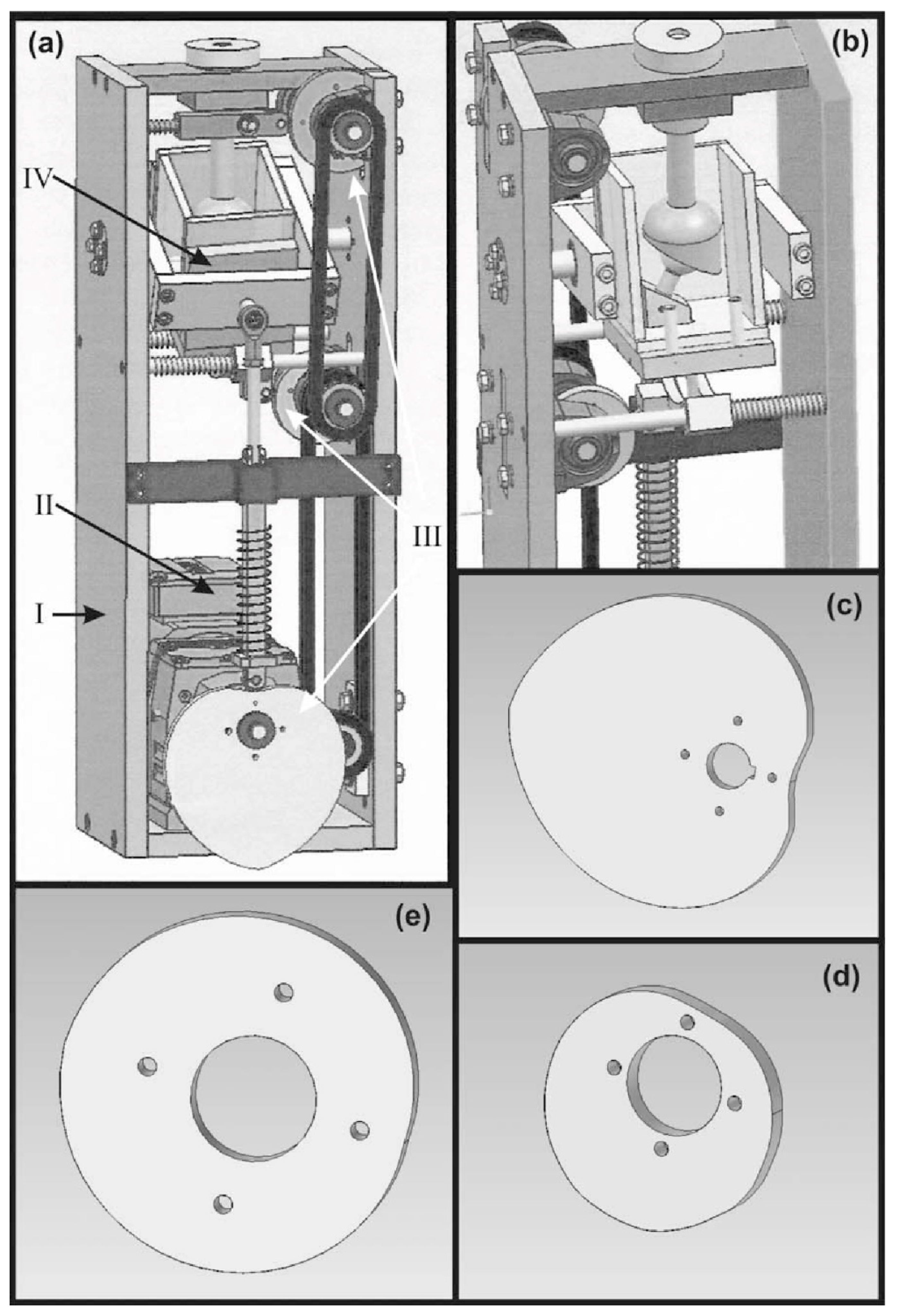
The main characteristics for the new concept of a 3-axis hip simulator were designed based on its capability to combine movements/rotations in the three important angles. The whole design was performed by using a CAD software at the Laboratory of Manufacturing Technology of the National Technical University of Athens. Furthermore, the whole design should have been foreseen a space for the motor, which will give rotation to the eccentric sheave of each axis, as well as a tank, filled with a fluid representing the environment inside the human body, where the implant will be immersed in. Following the limitations arisen, the design concept was conducted and is shown in
Figure 1.
The testing machine proposed herewith is consisting of four basic sets of parts, as listed below:
The main body of the simulator (I)
The electrical motor for rotating the eccentric sheaves through a system of driving chain and gear chain (II)
3 eccentric sheaves (III), one for each axis of movement, which give motion to the tank
The tank for immersing the implant, filled with a special fluid, which simulates the physiologic phenomena (IV)
After the design, the manufacturing of the simulator was proceeded. The parts of the machine were manufactured from a variety of materials so as to be near the specifications of the ISO standard. The material of the main body of the machine was the Aluminium Alloy 7075T6 but also there were used materials like Ti6Al4V for the stem part as well as Stainless Steel 316L and plastic parts of Plexiglass for the tank. The properties of the material are described in
Table 1.
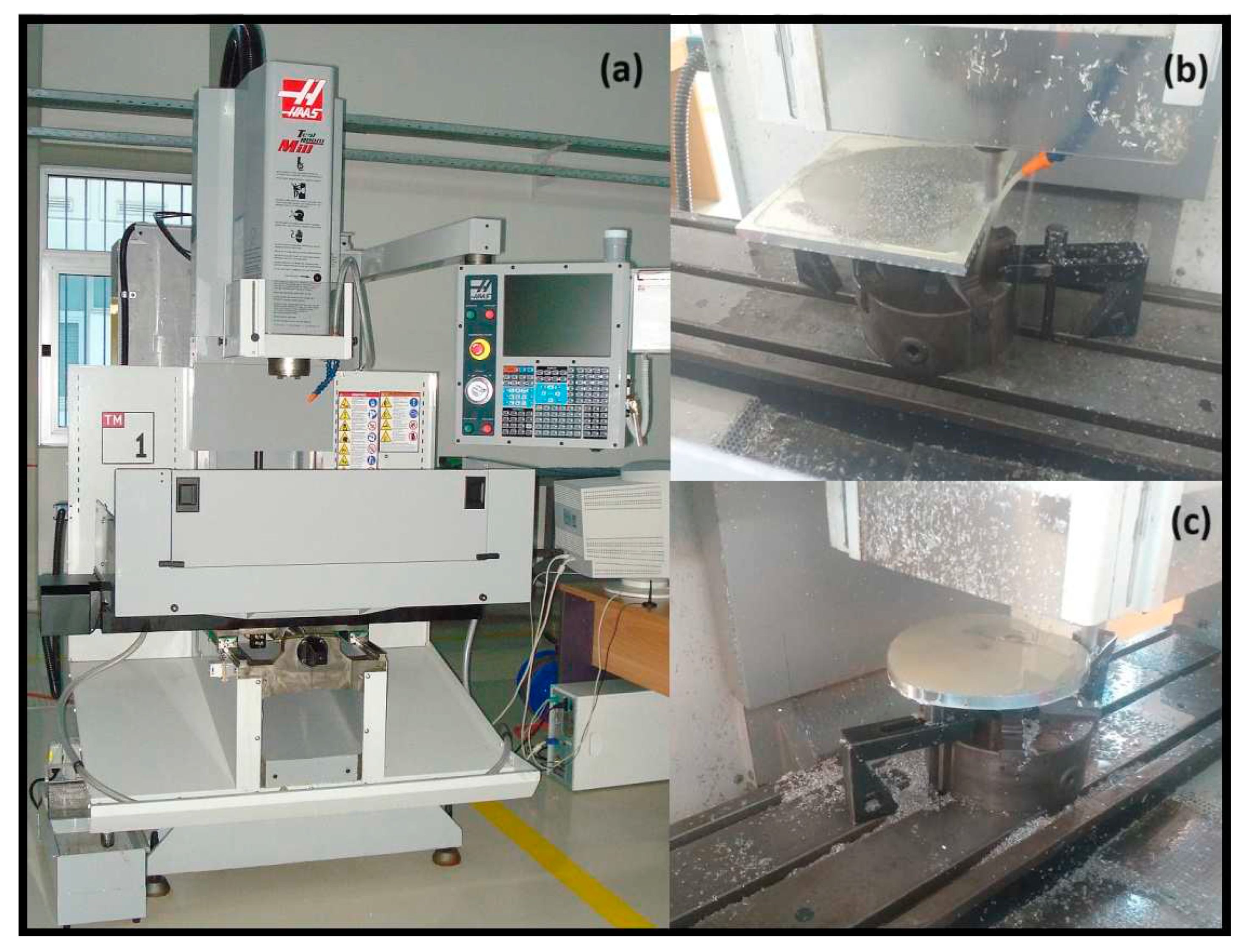
The whole manufacturing took place in the Laboratory of Manufacturing Technology of the National Technical University of Athens using both compatible Machine Tools and CNC milling. The parts that were manufactured in CNC Milling machine were the eccentric sleeves and the acetabular cup holder.
For these parts the manufactured procedure took place after the G-code was exported from a CAM software in a Haas TM-1 Milling Machine. The tools that were used were YG End Mill and Ball End HSS 8% Co. The final product is shown in
Figure 2 after the finishing process.
Finally for the motion of the simulator, a 1.1kW motor was selected with an inverter so as to control its rotation and velocity through all the simulation procedure. The properties of the motor and its inverter are shown in
Table 2.
2.1. Assembly of the Simulator
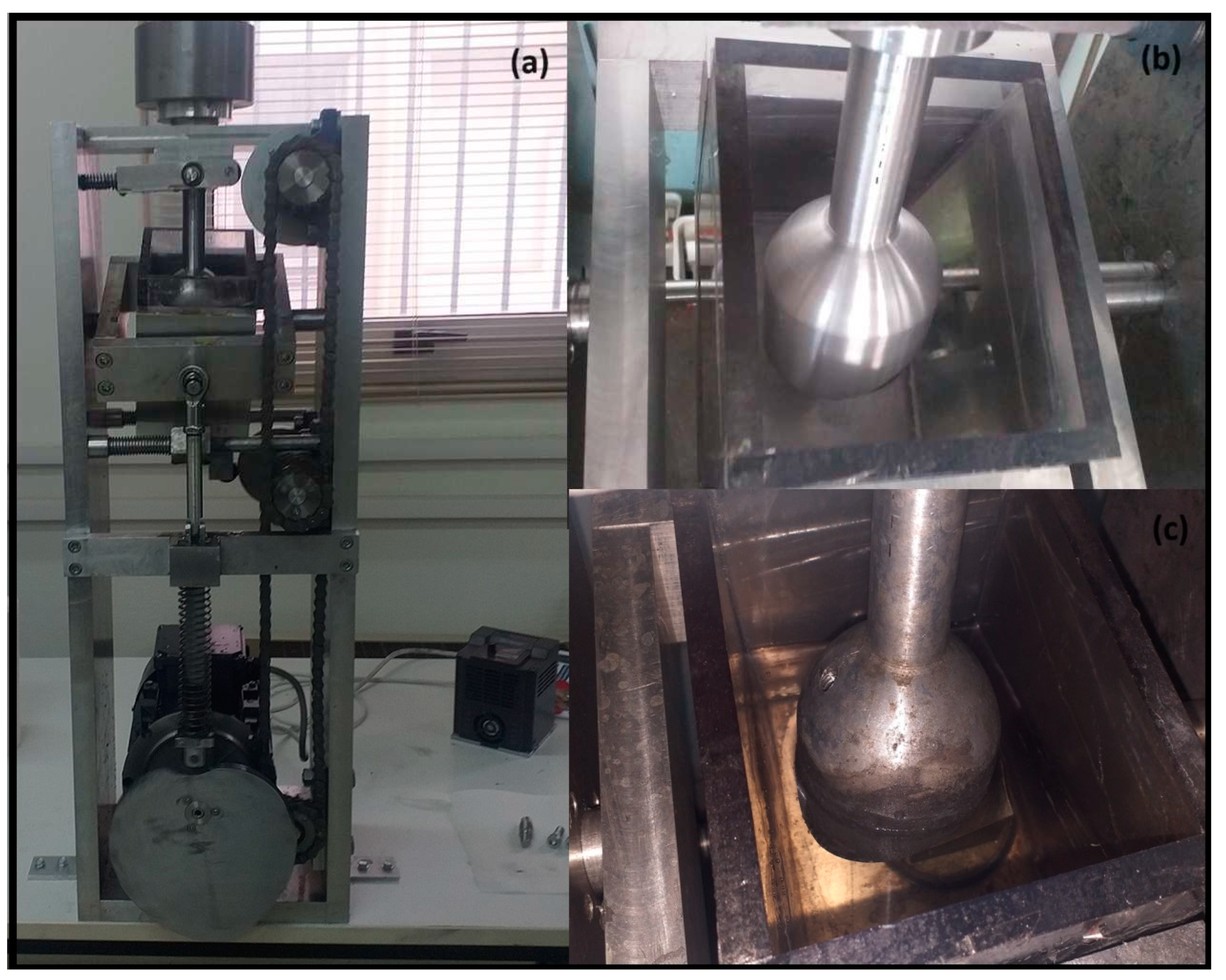
The simulator was assembled and installed in the laboratory as shown in
Figure 3. One of the main parts, is the tank where the hip implants are installed so as to be examined and evaluated. The tank is made of plexiglass so as to check the fluid through out the simulation. The fluid is bovine calf serum (LGC Biotecnologia, batch n° 02141-VT), diluted with deionized water to a protein concentration of 26.6 g∕L and filtered through a 0.1 μm filter to remove contaminants. For the minimization of bacterial and fungal degradation, a mass fraction of 0.2 % of sodium azide was added to the lubricant. [
5,
6]
The simulator is working continuously in all thre axis. During the wear experiments the rotation of the motor is setted through the inverter. The working rnage was between 2.5 – 4.4Hz so as to have a normal movement. Also in the top part of the simulator, there is a specific part so as to add weight in order to apply the appropriate force to the implant. During operation t it is possible to check the simulator every 8 hours so as to investigate the effect of the wear test on the implants. Through the experiment, real-time optical check of the tank is possible in order to observe the particles removed from the implants due to wear blurring the bovine calf serum. Finally every 100,000 cycles the simulator can stop and if necessary remove easily the accetsabular part, so as to examine the implant.
3. Results of the Simulator Evaluation
The simulator was manufactured, under the scope of the research program that was dealing with new ceramic coatings on metallic resurfacing implants. According to the program, custom hip implants are designed, personalized on the patient needs, and manufactured through 3D printing using Ti6Al4V alloy.
The implants after their construction were treated in the Laboratory of Metallurgy and MIRTEC, so as to receive the proper surface treatment and ceramic coatings system on their sliding surfaces. During the coatings system optimization procedure, a significant number of different materials as well as layer structure and thickness were tested and evaluated.
Finally coated implants with systems of one and/or two layers were developed. In order to evaluate the simulator, a number of implants were tested, so as to see the areas of pressure, the implants wear, the motion of the simulator and the duration of the wear experiments. The wear simulations took place in the Laboratory of Manufacturing Technology. Below, the results for two types of implants will be presented. The first with a single porcelain layer and the second with a double coating system consisting of a a Sol-gel layer and a porcelain one.
3.1. Single porcelain layer
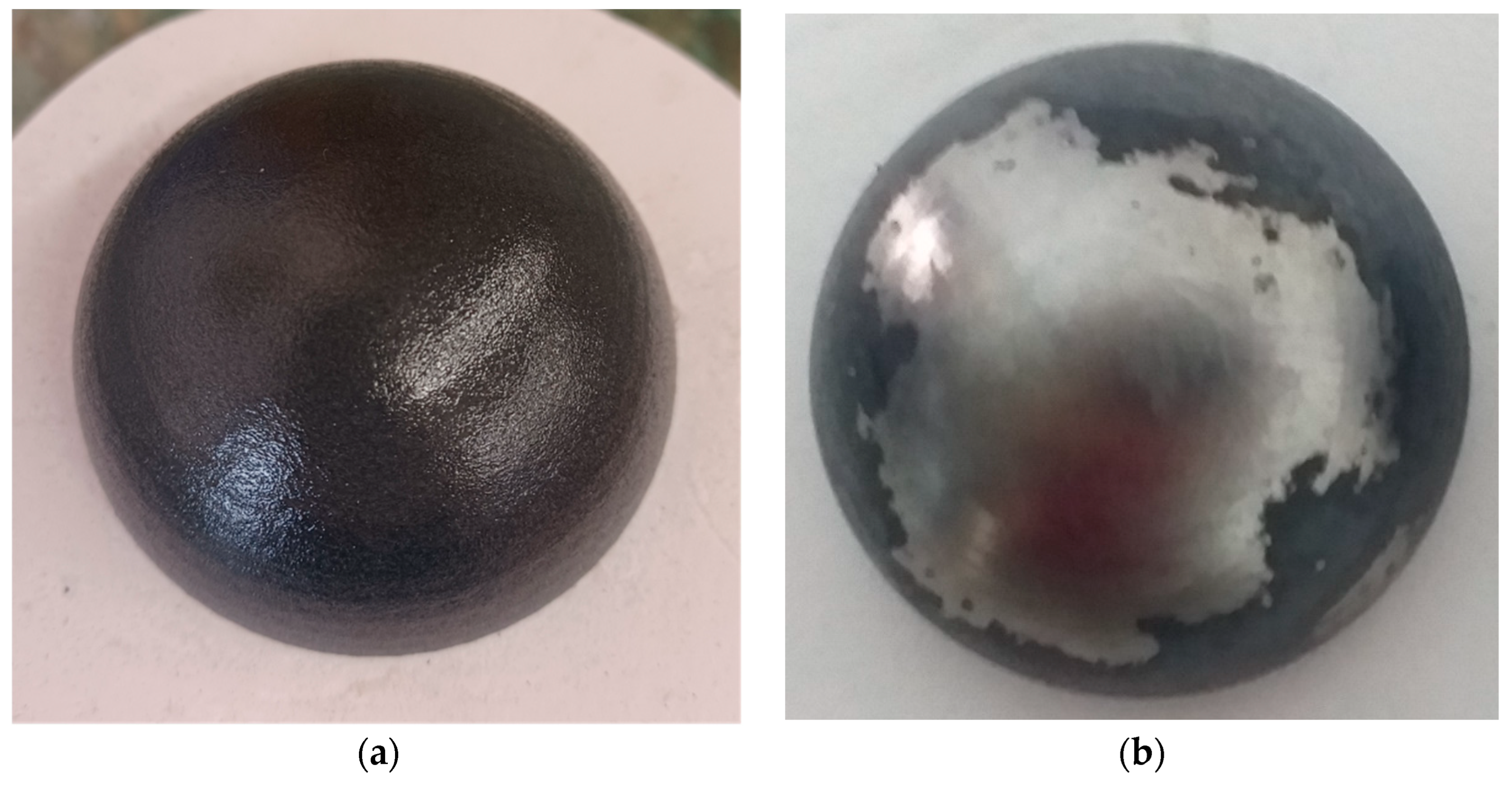
The first implant (a pair of acetabulum – head cup) was porcelain coated through spraying process. The single layer was very thin and estimated to be not more than 800 μm. The simulation for wear test was made after the coating was deposited, without other surface treatment (polishing etc.). The simulation was stopped at 400,000 cycles, since the wear of the implant was very obvious on the top of the head cup, as it can be seen in
Figure 4.
It is assumed that coating failure initiated at the top of the part and through the test wear was expanded peripherally to the outer diameter. According to this, it was estimated, that the layer was delaminated in the top of the implant, maybe due to its low thickness and its high roughness. This delamination was caused by the removed from the layer particles that remained at the spacing between the two moving parts (acetabulum – head cup) which finally ended in the serum. As expected, delamination was expanded to the whole upper surface of the head cup.
3.1. Double Sol-gel and porcelain layer
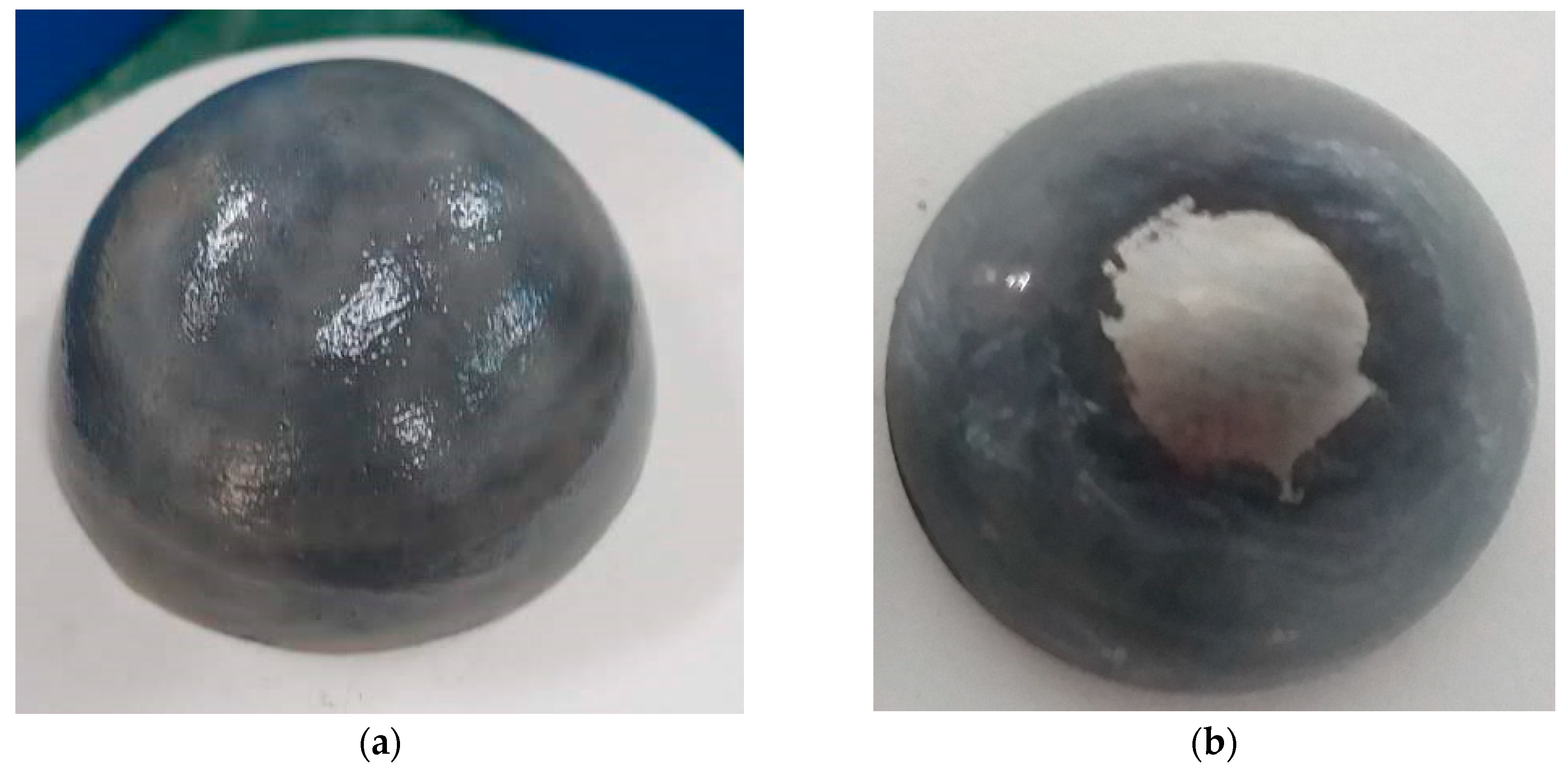
The second implant was coated with an intermediate sol-gel layer followed by a porcelain layer deposited using paint brush. The double layer was thin and was estimated to be not more than 1.8 mm. The simulation for wear test was made after the coating was deposited, without any other surface treatment (polishing etc.). The simulation was stopped again at 400,000 cycles, since the wear of the implant was again very obvious on the top of the implant, as seen in
Figure 5.
As it can be seen in
Figure 5, the wear of implant was severe but much better compared to the single layer implant. It has been started from the top of the implant and during testing it was expanded peripherally to the outer diameter.
According to the results from the second implant pair, it is assumed, that the layer delamination originated again at the top of the implant, due to high surface roughness, expanding to the whole upper surface due to particles remaining between the sliding implant surfaces in the serum.
A third hip resurfacing implant (acetabulum – head cup) coated with the same intermediate sol-gel layer followed by porcelain layer was examined for a total of 100,000 cycles and no major marks or cracks on the porcelain ceramic layer apart from one small crack in the inner surface of the acetabulum part, as shown in
Figure 6.
4. Discussion
Based on the results of the simulation a number of deductions were extracted. The implants evaluated in the simulator were moving with simultaneous load application, the area that presented the major wear problem was the upper top of the head of the bone part. According to literature review the wear-pattern from heads to cup is in the middle upper point with elliptical area of 1668 mm
2 spread to one side. Also, the acetabular cup has three wear patterns areas of 442 mm
2 eccentric of the main axis at inclinations of 35
O, 50
O and 60
O [
7].
Furthermore, according to the movement and the position of the implants (head and cup) during the simulation a separation mechanism is identified. Through this mechanism the position of two parts change simultaneously during the simulation, and the force acted on the surfaces changes as well, having a major and a minor value. This action results so that the wear starts from the top and the near area [
8].
According to the above, the implants tested had a major wear in the upper area. The area of the wear in heads, came close and through the limits of the 1668 mm2 and in the acetabular cup the crack started in an area with inclination of 45o of the main axis. Also, through the motion mechanism, the wear was expanded to the area of the upper top point. This is the result of the fact that the simulator is working under the conditions that the majority of similar machines do, according to reviews, but has additionally the advantage that can make the movement in 3 axes simultaneously. Furthermore, the use of different motors with individual inverter in each axis can achieve a difference in the motion. Each axis can move independently, with different rotation velocity but again simultaneously. This will lead to a different pattern of motion and can make the wear test complex and give more conclusions.
Another deduction was that the roughness may play a tremendous role to the wear fracture. Both implants were not treated after the coating deposition. Their roughness was not measured and not any polishing method took place. So, there is a big possibility, that through the surface roughness, a number of particles were delaminated and the wear was started in the very beginning of the simulation. This leads to the fracture of coatings after 400000 cycles not permitting any more experiments. The implants roughness is very important and follows strict limitations according to ISO standards.
However, the implant with the double layer showed better results compared with the single one, the wear area was smaller and the delamination was started after the 100,000 cycles. Additionally, it should be noted that the thickness was bigger giving the opportunity of less wear compared with the thicker one. More surface treatments have to take place, and the surface roughness must be improved.
5. Conclusions
To conclude this paper has to do with the manufacturing of a new 3-axis hip joint simulator. The manufacturing was made from typical materials and the simulator took motion from a motor including inverter, and through three eccentric sleeves that give motion to the experimental tank where the implants are set. The motion is simultaneous in 3 axes and have the same rotation velocity. Future design can give the opportunity to control each axis with different motor. Finally, the simulator was evaluated, by checking hip resurfacing implants made of Ti6Al4V with ceramic coatings, and the results showed that the simulator is working under the conditions that the majority of similar machines do.
Author Contributions
Conceptualization, N. Galanis and E. Roussi; methodology, N. Galanis and E. Roussi; validation, I. Kitsou, I. Georgiopoulos and C-D Andreouli; investigation, N. Galanis and E. Roussi; resources, I. Georgiopoulos and C-D Andreouli; writing—original draft preparation N. Galanis; writing—review and editing, E. Roussi and D. Manolakos; visualization, N. Galanis.; supervision, D. Manolakos, A. Tsetsekou and C-D Andreouli; project administration, I. Kitsou.; funding acquisition, A. Tsetsekou. All authors have read and agreed to the published version of the manuscript.
Funding
This research has been co-financed by the European Regional Development Fund of the European Union and Greek national funds through the Operational Program Competitiveness, Entrepreneurship and Innovation, under the call RESEARCH – CREATE – INNOVATE (Project Code: T2EDK-02410).
Conflicts of Interest
The authors declare no conflict of interest; The funders had no role in the design of the study.
References
- Cao, S.; Mischler, S. Assessment of a recent tribocorrosion model of wear of metal-on-metal hip joints: Comparison between model predictions and simulator results Wear 2016, Volume 362-363, pp. 170-178. [CrossRef]
- Ramamurti, B.S.; Estok, D.M.; Jasty, M.; Harris, W. H. Analysis of the Kinematics of Different Hip Simulators Used to Study Wear of Candidate Materals for the Articulation of Total Hip Arthroplasties. Journal of Orthopaedic Research 1998, Volume 16, pp 365-369. [CrossRef]
- Cheng, G.; Lu, J.L.; Gu W. Kinematic analysis of 3SPS + PS bionic parallel test platform for hip joint simulator based on unit quaternion. Robotics and Computer-Integrated Manufacturing 2012, Volume 28, pp. 257-264. [CrossRef]
- Galanis, N.I.; Manolakos, D.E. Design of a Hip Simulator According to the ISO 14242. In Proceedings of the World Congress on Engineering 2011, London, U.K., 6-8 July 2011.
- Harsha, A P; Joyce, T.J. Challenges associated with using bovine serum in wear testing orthopaedic biopolymers. Proceedings of the Institution of Mechanical Engineers, Part H: Journal of Engineering in medicine 2011, Volume 225 Issue 10, pp 948-958. [CrossRef]
- Trommer, R M; Maru, M.M. et al. Multi-Scale Evaluation of Wear in UHMWPE-Metal Hip Implants Tested in a hip Joint Simulator, Biotribology 2015, Volume 4, pp 1-11. [CrossRef]
- Clarke, I. C.; Halim, T.; Smith, E. J.; Donaldson, T. K. Acetabular Cups in 60mm Metal-on-Metal Bearings Subjected to Dynamic Edge-Loading with 70O Peak-Inclination in 10-Million Cycle Simulator Study. Lubricants 2017, Volume 6,1. [CrossRef]
- Saikko, V. Adverse condition testing with hip simulators. Biotribology 2015, Volume 1-2, pp 2-10. [CrossRef]
|
Disclaimer/Publisher’s Note: The statements, opinions and data contained in all publications are solely those of the individual author(s) and contributor(s) and not of MDPI and/or the editor(s). MDPI and/or the editor(s) disclaim responsibility for any injury to people or property resulting from any ideas, methods, instructions or products referred to in the content. |
© 2023 by the authors. Licensee MDPI, Basel, Switzerland. This article is an open access article distributed under the terms and conditions of the Creative Commons Attribution (CC BY) license (http://creativecommons.org/licenses/by/4.0/).
