Introduction
Steels used for mining tools face severe wear and degradation in the challenging conditions of the mining industry. Recognizing the evolving landscape of additive manufacturing, this study delves into the replacement of conventional hard-facing with Laser Metal Deposition (LMD), an emerging and advanced additive manufacturing process. LMD offers advantages such as low dilution, rapid processing, automation capabilities, energy efficiency, and the ability to form thin layers, setting it apart from conventional arc welding methods. There are many studies in literature on laser metal deposition and its applications on to various materials. [
1,
2,
3,
4,
5]. Inspite of having huge applications tehre are also challenges in understanding the final properties of the materials after LMD. Such understanding will help the researcher to investigate and develop better deposition of the materials with higher life spans.
In this investigation, the focus shifts to the effect of LMD on heat-treated samples alloys 805M2, 832M13, and 827M40 (referred to as samples 1, 2, and 3, respectively in this paper). The research endeavors to comprehensively characterize the metallurgical bond of the LMD process overlay on heat-treated samples, utilizing microstructural analysis, hardness distribution assessments, and an exploration of the dilution effects of the WC/NiCrB mixed overlay on the heat-treated alloy steel. This study represents a significant step forward in understanding the nuanced interplay between additive manufacturing processes, metallurgical properties, and the performance of heat-treated alloy steels in critical mining tool applications.
Materials and Methods
The following materials were utilized:
Table 1.
Chemical composition of the powders.
Table 1.
Chemical composition of the powders.
| |
Elements wt.% |
| Ni |
Cr |
B |
Si |
| NiCrSiB |
78 |
10-15 |
1.5-3.0 |
3-5 |
| WC |
60 |
NiCrBSi Alloy: A self-fluxing alloy known for its low melting point and advantageous properties, including corrosion resistance, fatigue strength, galling resistance, and fretting fatigue resistance [
6,
7,
8,
9].
Tungsten Carbide (WC): An abrasive material employed to enhance wear resistance, abrasive resistance [
6,
7,
8,
9,
10,
11]. Notably, a significant discrepancy in melting temperatures was observed between WC (2850°C) and NiCrBSi (1180°C) [
11,
12,
46]. Additionally, WC-Fe displayed almost double the thermal conductivity of nickel, introducing a compelling contrast in thermal behavior.
Substrate Materials: In this study, distinct alloy steels namely 805M2(sample 1), 832M13(sample 2), and 827M40(sample 3), with enriched surface carbon content 0.6% were employed as substrate materials to assess the impact of surface modification on abrasion resistance.
Surface Modification Techniques
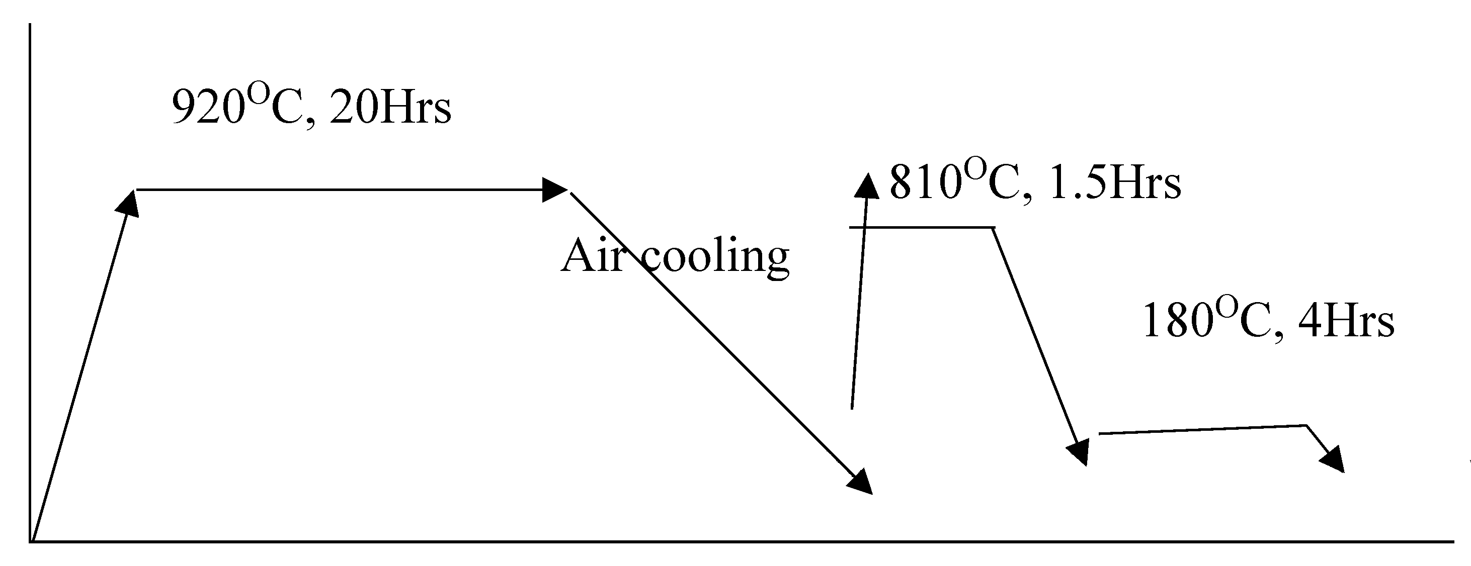
In the initial phase of this study, samples underwent a meticulous gas carburizing process followed by hardening and tempering treatments, resulting in a judicious carbon enrichment on the surface and within a depth range of 0.3 mm. The gas carburization process was meticulously administered to the steel samples, subjected to a requisite heat treatment at 920°C with precise control of carburizing potential within the range of 0.9 to 1.2 carbon potential (cp). The attained carbon content measured between 0.6% to 0.7%, culminating in a significant enhancement in surface hardness to an impressive 720 HV 0.5. This transformation was achieved through a well-defined quenching and tempering (Q/T) cycle, as elucidated in the in fig … Later these case carburized steels were subjected to LMD treatment. This innovative additive fabrication method introduces an extra layer of intricacy to the metallurgical features of the samples, providing a nuanced comprehension of the interaction between laser deposition and the inherent material characteristics. The ensuing analysis aims to unveil the synergistic effects and performance implications arising from the integration of gas carburizing, traditional heat treatment, and LMD, thereby contributing valuable insights to the domain of surface engineering and advanced materials processing.
Figure 1.
Heat treatment cycle with x-axis (Time) and Y-axis (Temperature) for gas carburisation of the steels.
Figure 1.
Heat treatment cycle with x-axis (Time) and Y-axis (Temperature) for gas carburisation of the steels.
Laser Metal Deposition (LMD)
The Laser Metal Deposition (LMD) process was meticulously executed on the machine-finished surface of the pre-heat-treated samples, which were subsequently subjected to shot-blasting to eliminate scales formed during the initial heat treatment. The substrate's heat treatment cycle, as depicted in
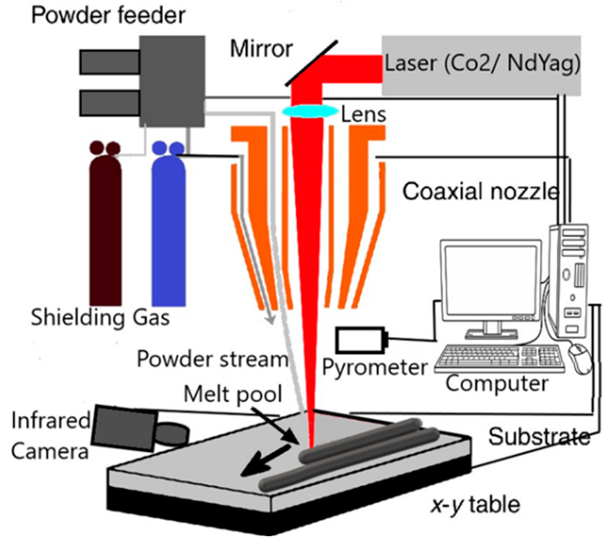
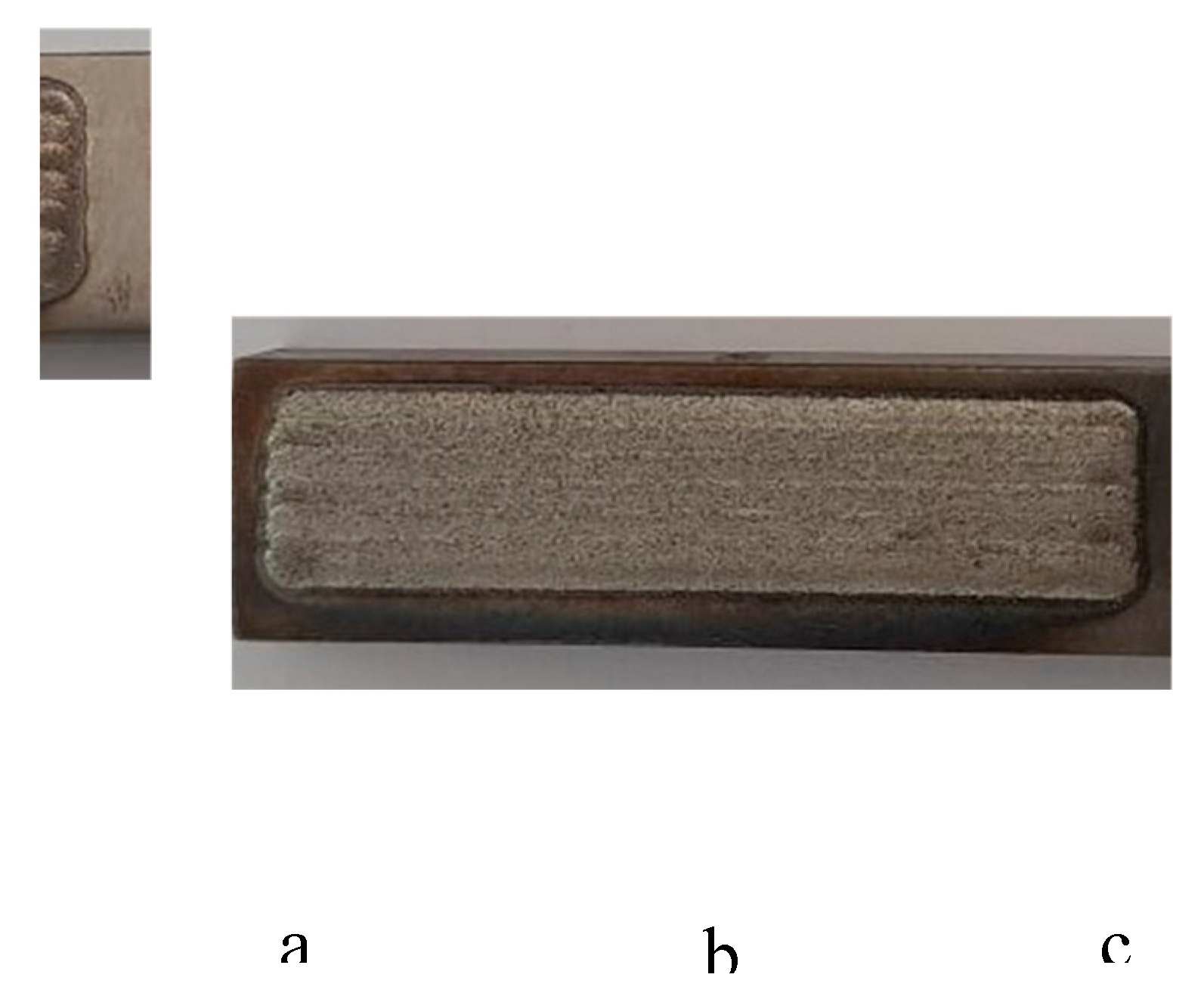
Figure 2, served as a foundational framework for this transformative overlay. Employing a high-energy CO2 laser machine manufactured by KUKA, featuring a coaxial laser head system and boasting a formidable laser power of 2kW, the LMD procedure unfolded on meticulously fixed rectangular samples positioned on a metallic table, as illustrated in
Figure 2. The layer-by-layer deposition of powder onto the samples was facilitated by the precision of the LMD machine. The utilization of this cutting-edge technology allows for a nuanced investigation into the interplay between the laser metal deposition process and the existing material attributes. The experimental parameters employed during these crucial procedures are comprehensively detailed in
Table 2, providing a systematic foundation for the subsequent analysis and interpretation of the samples' metallurgical characteristics and mechanical properties.
For a comprehensive microstructural and microhardness analysis, Laser Metal-Deposited samples underwent precise sectioning using Electrical Discharge Machining (EDM) wire along the transverse sections. Both segmented specimens were meticulously prepared for metallography by mounting them on bakelite, ensuring uniformity in the analysis process. Subsequently, the fully prepared samples underwent controlled etching with a 5% nital solution. The intricacies of the resulting microstructures were then scrutinized with a Leica optical microscope, providing detailed insights into the material morphology. Additionally, a scanning electron microscope (SEM) manufactured by Carl Zeiss was employed to further elucidate the finer details of the microstructural characteristics. This dual-method approach, combining optical and electron microscopy, facilitates a comprehensive understanding of the Laser Metal-Deposited samples, offering a nuanced exploration of their internal features and microhardness profiles.
In the LMD process
Table 2, laser power (P) influences the heat input and material melting, while the scanning speed (S) controls the rate of material deposition. Adjusting the powder feed rate (F), laser diameter (d), overlap, and energy density (E) allows precise control over the resulting material properties and geometry.
In
Figure 3 and
Figure 4, metallography samples, encapsulated with Bakelite mounting, underwent rigorous examination using a light optical microscope to facilitate qualitative analysis. The determination of case depth, a critical parameter indicative of the surface modification's effectiveness, was systematically conducted across all specimens. For samples subjected to a quenching and tempering regimen, the effective case depth (ECD) was meticulously assessed utilizing Leco Micro hardness testing, revealing values ranging approximately between 1.5-1.8mm. Notably, the total case depth (TCD) for sample 2 exhibited a range of 2.0-2.2mm, with an ECD averaging at 0.9-1.0mm and an overall average TCD of 1.5mm. The precision of these measurements was further confirmed through comprehensive analysis using a Leica microscope, contributing to a thorough understanding of the surface-modified samples' structural characteristics and case depth profiles.
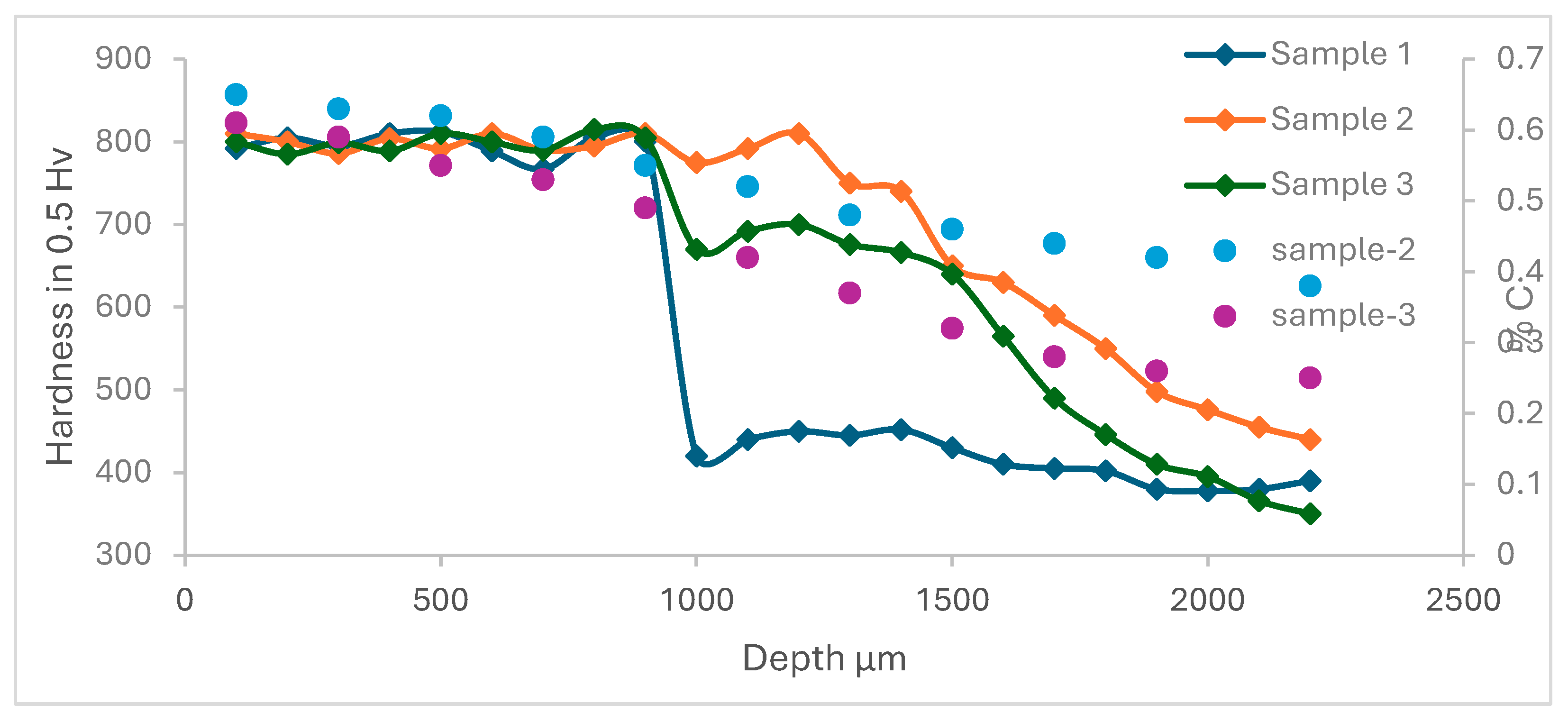
The initial assessment of the overlayed samples entailed a examination of hardness measurements, with a comprehensive hardness profile extending from the interface to a depth of 2.5 mm. The investigation aimed to elucidate the dilution effects and metallurgical strength inherent in the samples. As delineated in
Figure 6, the hardness profile across the interface to the Heat-Affected Zone (HAZ) in the hard-faced deposition under gas carburized conditions exhibited a discernible contrast, manifesting lower case and core hardness in this specific region. Contrarily, samples subjected to gas carburization followed by hardening and tempering displayed unaltered mechanical properties. Typically, a gas carburized sample in quenched and tempered condition showcased a hardness ranging between 650 to 750 HV. In contrast, post-deposition, the same samples exhibited a notable increase in hardness, reaching up to 800 HV. Intriguingly, the gas carburized sample exhibited a phenomenon of hardness drop within a few microns of depth, attributed to the abrupt heat and cooling cycles inducing localized softening in the steel substrate. This nuanced exploration of hardness profiles provides valuable insights into the intricate dynamics of surface modification processes and their impact on the mechanical properties of the treated samples.
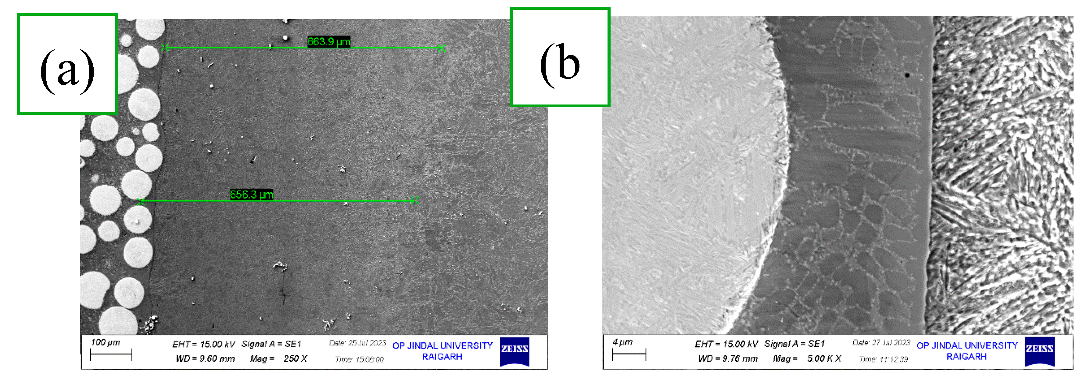
The microstructure analysis of the samples, presented in polished and etched conditions in
Figure 7 and
Figure 8, respectively, revealed notable variations in each heat-treated sample. A discernible disparity in Martensite morphology and its distribution was observed from the interface to the case. In
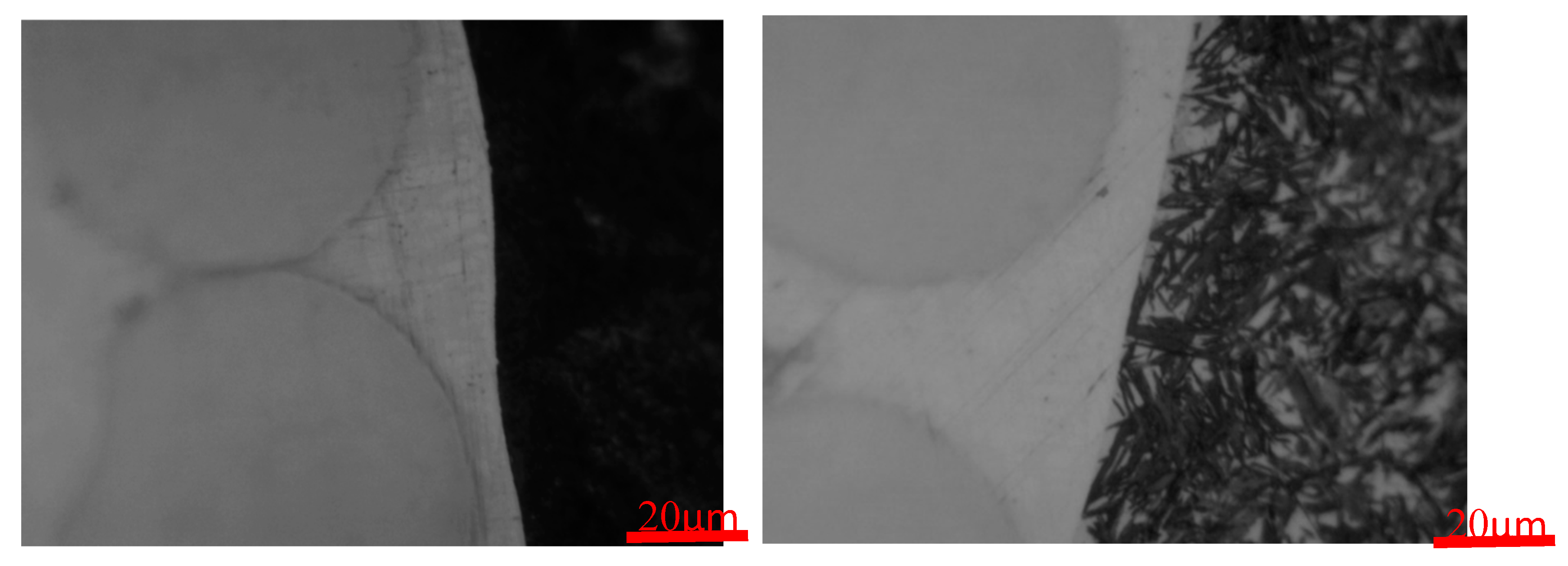
Figure 7b, at a proximity of 0.1mm to the interface, a high-carbon tempered martensite with 30% retained austenite was evident. Further, at a depth of 1.5mm from the surface, a combination of plate-type and lath-type morphologies was discernible. In
Figure 5b, the presence of martensite and retained austenite in the stress-relieved annealed sample affirmed that this region underwent hardening owing to the rapid heating and cooling imparted by the high-energy laser. Notably, the formation of austenite at the interface exceeded that of the adjacent portion in the substrate, indicative of faster heat conduction at the interface compared to a depth of 1 mm from the interface. This resulted in the formation of high-carbon plate-type martensite near the interface, offering valuable insights into the intricate microstructural changes induced by the laser deposition process.
Figure 5.
a) sample 1: showing interface; b) sample 2: showing interface indicates Retained austenite 30% and Tempered martensite.
Figure 5.
a) sample 1: showing interface; b) sample 2: showing interface indicates Retained austenite 30% and Tempered martensite.
The increased formation of austenite observed at the interface surpassed that of the adjacent substrate portion, underscoring the dynamic thermal processes inherent in this transformative surface treatment. The accelerated conduction of heat at the interface, as compared to a depth of 1 mm from the interface, delineates a nuanced heat transfer mechanism crucial in the formation of intricate microstructures. Notably, the proximity to the interface witnessed the formation of high-carbon plate-type martensite, highlighting the localized thermal effects and rapid cooling conditions characteristic of the high-energy laser-assisted process. This distinctive microstructural evolution near the interface provides compelling evidence of the interplay between thermal dynamics and material transformation, offering profound insights into the tailored enhancements achieved through LMD process.
Figure 6.
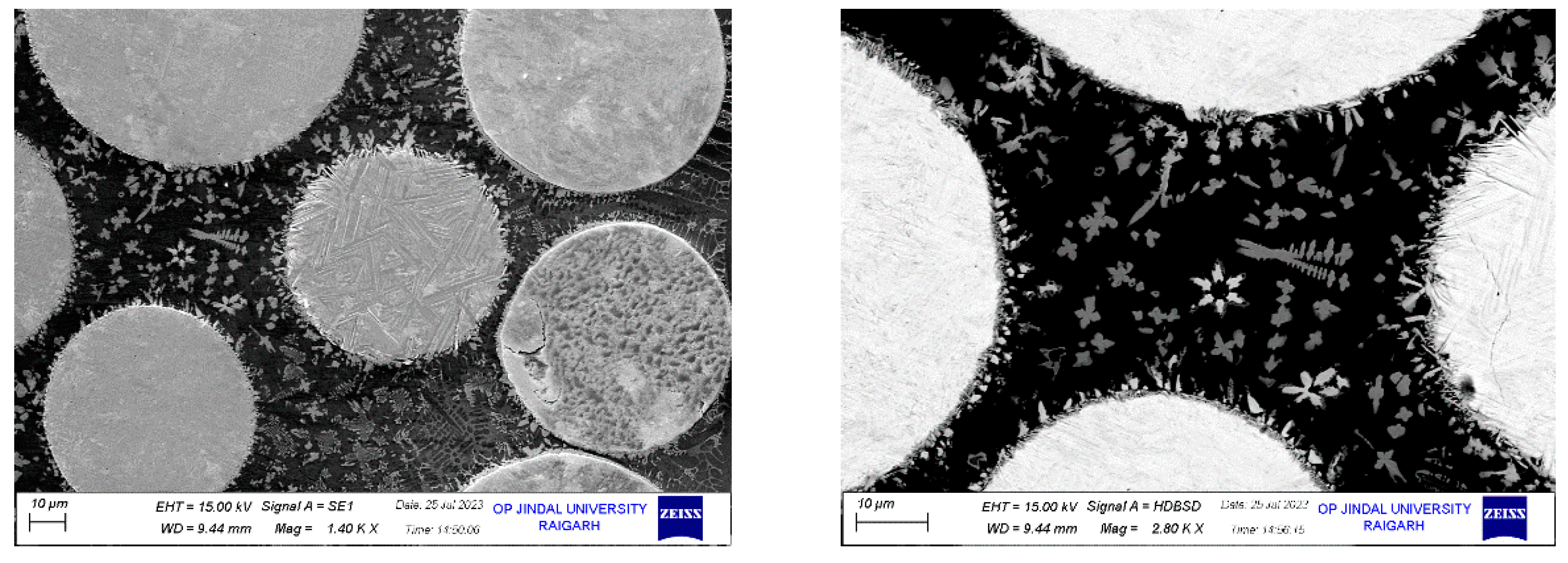
Micro-structure of Laser metal deposition of metal matrix.
Figure 6.
Micro-structure of Laser metal deposition of metal matrix.
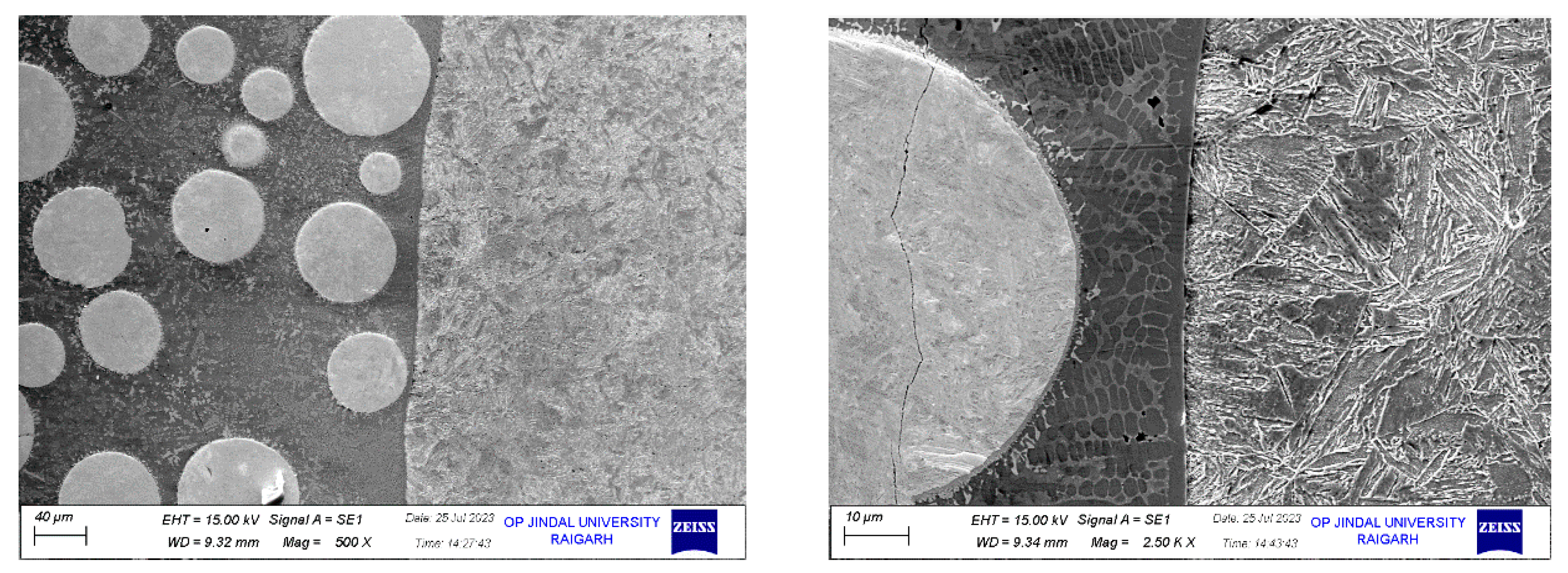
The microstructure examination, as presented in
Figure 7,
Figure 8 and
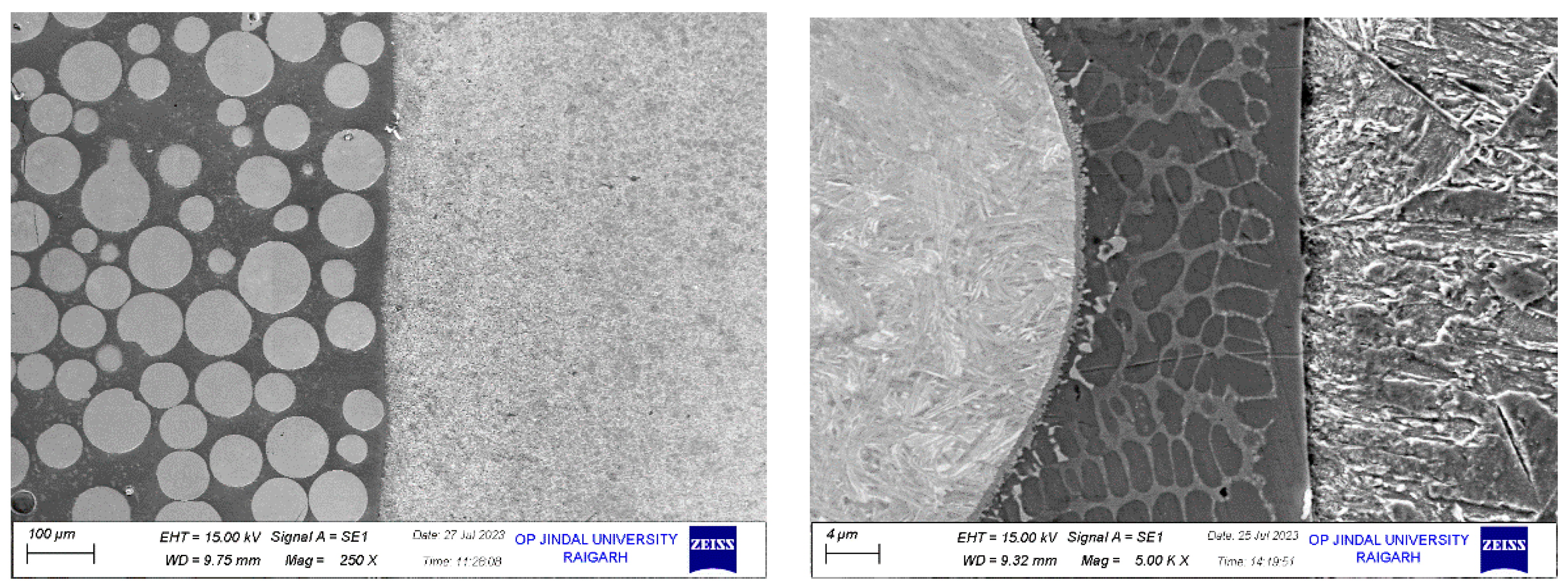
Figure 9, reveals the outstanding quality of the interface between the substrate and overlay. The absence of cracks or de-lamination defects underscores the success of the deposition process in achieving a strong bond between the two materials [
26,
27,
29].
The meticulous distribution of WC particles within the Ni matrix is a testament to the precision and effectiveness of the surface modification technique, further contributing to the enhancement of material properties. The presence of minuscule pores, particularly in the interface region, is a point of consideration. While their impact on the overall performance should be assessed, their presence does not diminish the overall achievement in creating a robust and cohesive interface.
Figure 7.
Sample 1: The interface exhibits the metallurgical bonding between steel and Laser Metal Deposition (LMD) of WC-NiCrBSi.
Figure 7.
Sample 1: The interface exhibits the metallurgical bonding between steel and Laser Metal Deposition (LMD) of WC-NiCrBSi.
Figure 8.
Sample 2: The interface exhibits the metallurgical bonding between steel and Laser Metal Deposition (LMD) of WC-NiCrBSi, indicates gas carburizing case depth.
Figure 8.
Sample 2: The interface exhibits the metallurgical bonding between steel and Laser Metal Deposition (LMD) of WC-NiCrBSi, indicates gas carburizing case depth.
Figure 9.
Sample 3: The interface exhibits the metallurgical bonding between steel and Laser Metal Deposition (LMD) of WC-NiCrBSi.
Figure 9.
Sample 3: The interface exhibits the metallurgical bonding between steel and Laser Metal Deposition (LMD) of WC-NiCrBSi.
Microstructure and Evaluation Near Interface Hardface Layer
Upon subjecting the Ni matrix to chemical etching using a mixture of 5% HNO3 in 95% Methanol, a distinct dendritic structure emerges. This dendritic structure, in line with the cooling direction, is characterized by a composition of 74% Ni, 6% Cr, and 10% W near the steel substrate. The interface zone, deeper in colour, exhibits a composition rich in Fe and Ni. These distinct domains result from complex chemical reactions during the hard facing operation.[
47]
Transformation of WC Particles
Ni matrix liquefies, enabling WC particle dissolution, with a size reduction at interfaces. Smaller particles favour dissolution, releasing carbon (C) that diffuses, forming intermetallic (Cr23C6) and eutectic phases (W2C) near WC particles. These changes account for the heightened microhardness in hard-faced layers. [
26,
27,
29,
46]
W → W2C → WC (Equation 1) [
46]
The presence of additional phases within the Ni matrix, including W4Ni [
31], can be at-tributed to the high melting point of W and its relatively generous solubility threshold in Ni, as per the W-Ni binary phase diagram. As the temperature recedes, dendritic phases with a high Ni content but low W content form [
32].
The entrainment of W within the matrix, fragmentation of diminutive WC particles, and alteration of WC particle morphology collectively poses challenges to the wear resistance of the WC particle-reinforced composite. The formation of intermetallic phases within the Ni matrix results in a reduction in matrix ductility, which can adversely affect wear resistance [
26,
32].
To mitigate this effect, careful control over the chemical composition and structural attributes of the WC particles, as well as judicious manipulation of matrix alloy parameters, becomes imperative. The size and configuration of WC particles also need to be considered to ensure their equitable dispersion within the matrix. The selection of an appropriate matrix alloy plays a critical role in shaping the wear and abrasive characteristics of the layer, striking a balance among mechanical properties like hardness, strength, and ductility.
The gradual transformation of Ni's microstructure from a dendritic morphology (
Figure 7,
Figure 8 and
Figure 9) near the substrate to an equiaxial configuration surrounding larger WC particles can be attributed to shifting nucleation mechanisms [
30,
32]. WC particles serve as heat sources during the cooling process, fostering the formation of equiaxial-shaped phases near the WC particles. The presence of oxides and pores at this interface is influenced by factors such as the interaction of materials with ambient air at elevated temperatures during the thermal spray process and the impact velocity of interface particles.
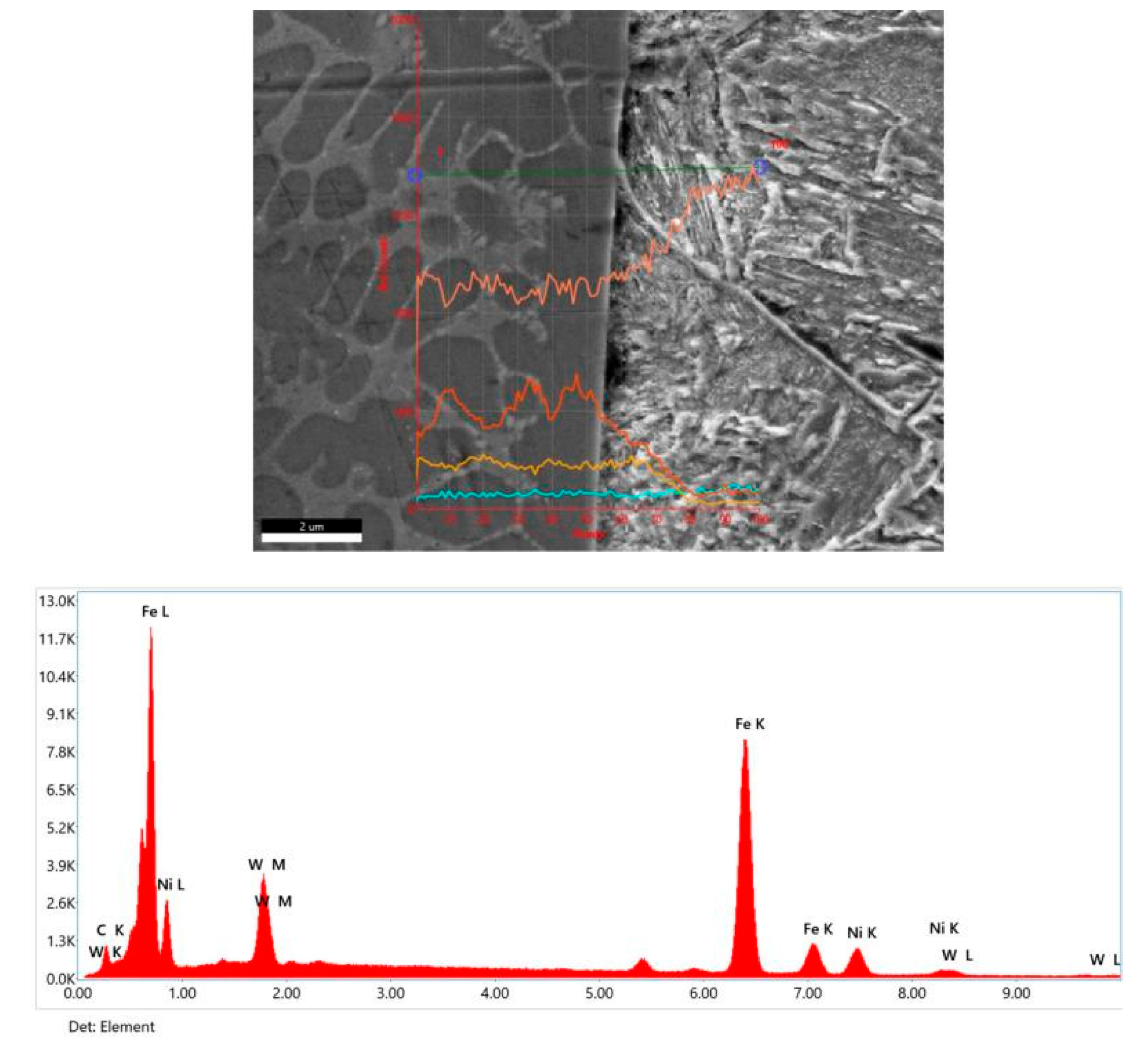
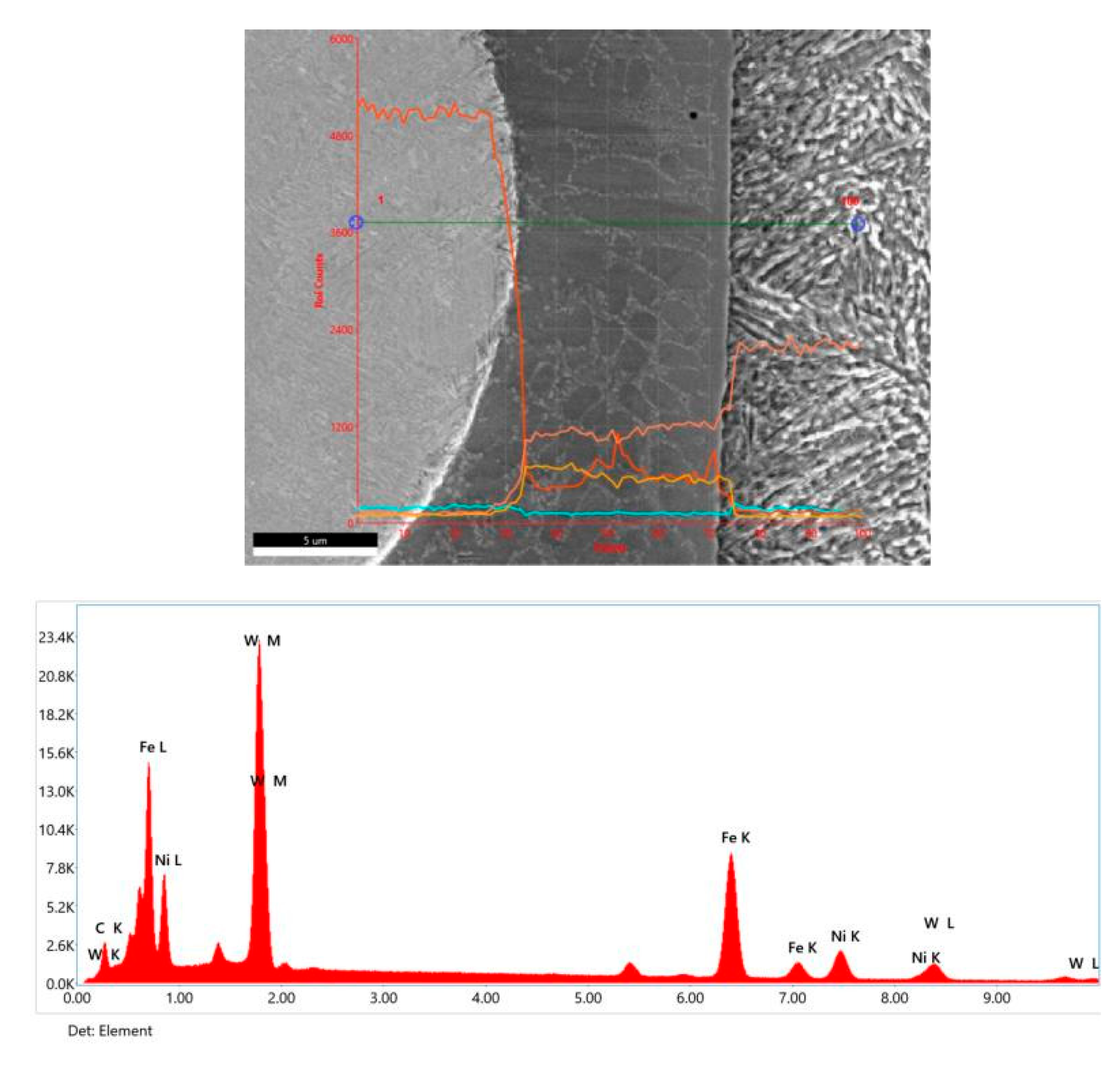
The interface between the WC-NiCrBSi-Fe alloy hard facing and the steel substrate is seamless, resulting from the interplay of Ni, Cr, Fe, and W [
37,
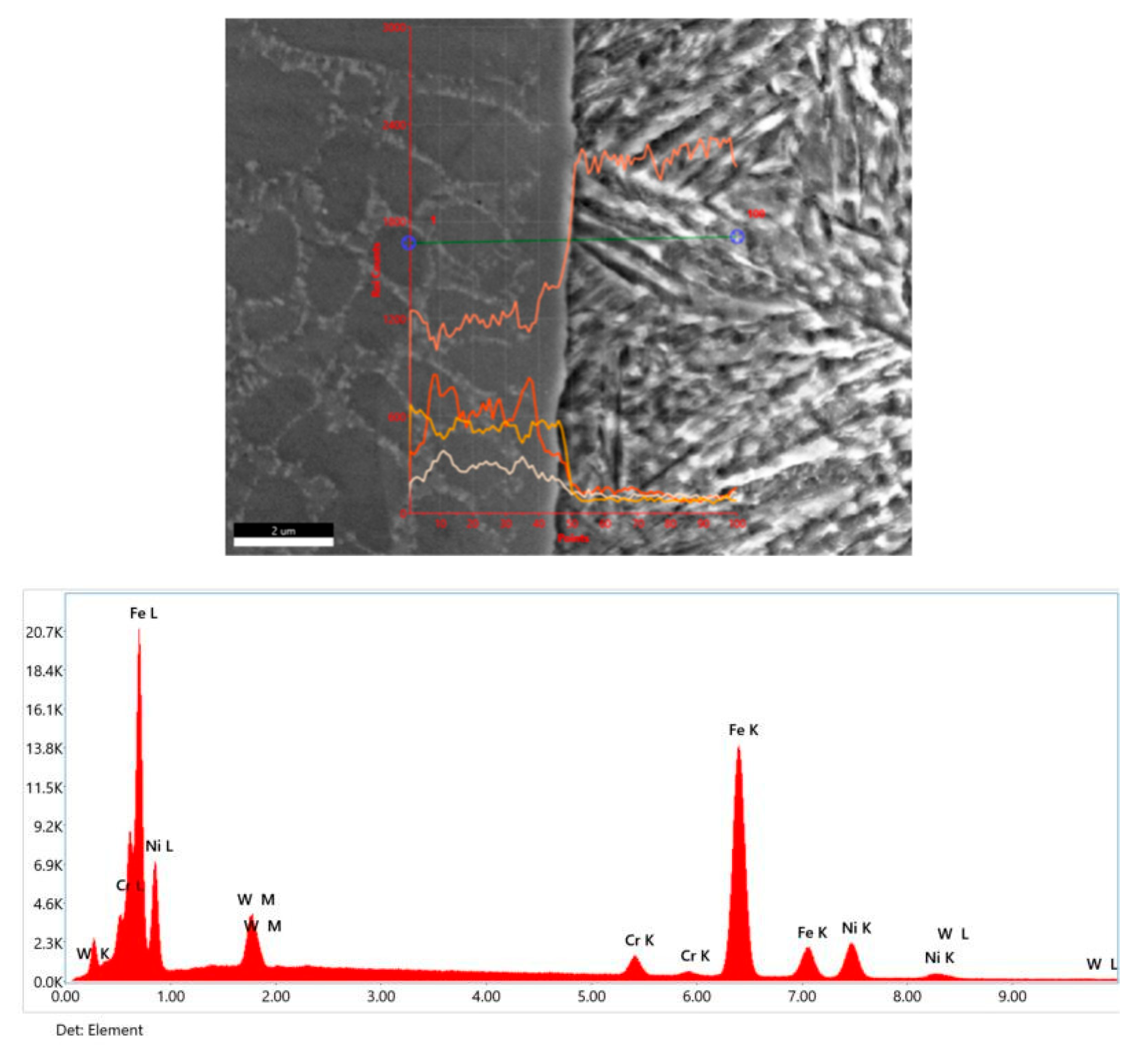
39]. SEM line scan analyses reveal shown in the
Figure 6,
Figure 7 and
Figure 8. the variation in chemical composition along the interfaces. The mutual solubility of these elements, particularly Ni and Fe, contributes to the inter-diffusion across the interface, strengthening the bonding and mitigating stress at the junction.
Figure 10.
Schematic of hardness profile measurements on the cross-section of a single bead.
Figure 10.
Schematic of hardness profile measurements on the cross-section of a single bead.
The SEM EDS analysis provides insight into the microstructural composition of the WC-NiCrBSi coatings and reveals the presence of various phases, including Ni/Ni3B, Cr7C3 carbides, and CrB borides [
46]. The microstructure of the composite coatings is complex, with NiCrW solid solutions, WC, Cr7C3, and Cr23C6, along with eutectic phases and oxides. The composition varies depending on the proportion of WC and matrix alloy in the coatings, impacting hardness and other mechanical properties [
46].
The microstructure and composition play a crucial role in the wear resistance and performance of hard-facing materials. The transformation of WC particles, the formation of intermetallic phases, and the evolution of microstructure provide insights for optimizing material properties in demanding applications.
Figure 11.
Sample 1 line scan from layer to steel surface; indicates martensite and elemental diffusion.
Figure 11.
Sample 1 line scan from layer to steel surface; indicates martensite and elemental diffusion.
Figure 12.
Sample 2 Line scan from hardface layer to steel; indicates high carbon martensite in interface drastic tungsten drop at interface.
Figure 12.
Sample 2 Line scan from hardface layer to steel; indicates high carbon martensite in interface drastic tungsten drop at interface.
Figure 13.
Sample 2 Line scan from hard-face layer to steel; indicates high carbon martensite in inter-face drastic tungsten drop at interface.
Figure 13.
Sample 2 Line scan from hard-face layer to steel; indicates high carbon martensite in inter-face drastic tungsten drop at interface.
The microstructure analysis provides valuable insights into the formation of intermetallic phases, the impact on wear resistance, and the intricate interplay of elements within the material. It also underscores the importance of carefully controlling the composition and structure of WC particles and the choice of the matrix alloy. The seamless interface between the hard facing layer and the steel substrate is vital in mitigating stress at the junction, contributing to the overall effectiveness of the coating.
Conclusions
In conclusion, this comprehensive investigation into Laser Metal Deposition (LMD)-engineered WC-NiCr layers on steels, has yielded valuable insights into the intricate interplay between metallurgical characteristics, mechanical properties, and surface modification processes. The application of LMD, replacing conventional hard-facing techniques, has proven to be a transformative approach, showcasing advantages such as low dilution, rapid processing, and the ability to form thin layers. The examination of heat-treated samples, encompassing alloys 805M2, 832M13, and 827M40, has provided a nuanced understanding of the metallurgical bond of the LMD process overlay. Despite a minor drop in hardness observed at the interface, particularly within the first 400 microns, the microstructural analysis has revealed a superior metallurgical bonding, underscoring the resilience of the Laser Metal Deposition technique. This study not only contributes to the foundational understanding of LMD-modified structures but also presents crucial data for optimizing the design and application of WC-NiCr-coated low carbon steels in diverse engineering scenarios, including the automobile and mining industries. The observed drop in hardness at the interface signifies a complex interplay between material properties, thermal effects, and the transformative potential of LMD, emphasizing the need for a holistic approach in evaluating the overall performance of surface-modified samples.
Author Contributions
Conceptualization, K.V.K. and M.K.P.; methodology, K.V.K.; software, M.K.P.; validation, K.V.K. and M.K.P.; formal analysis, K.V.K. and M.K.P.; investigation, K.V.K. and M.K.P.; resources, K.V.K. and M.K.P; data curation, K.V.K.; writing—original draft preparation, K.V.K.; writing—review and editing, M.K.P.; visualization, K.V.K.; supervision, M.K.P.; project administration, K.V.K. and M.K.P.
Funding
The project was self-funded and does not receive any funding.
Acknowledgments
Authors thank Central Instrumentation Facility (CIF) at OP Jindal University for the SEM characterization. VKK thanks Metallurgy staff at OPJU for their support in preparation of the samples. Authors MKP and VKK express thanks to the Management of OP Jindal University for their support and encouragement for conducting this research work.
Conflicts of Interest
I would like to declare there are no conflicts.
References
- Varun Kumar, K., & Kalyan Phani, M. (2022). Microstructural and mechanical characterization of parallel layered WC- NiCr weld overlay on 080 M40 steel substrate prepared using additive manu-facturing. Materials Today: Proceedings, 67, 501–506. [CrossRef]
- da Silva, L. J., & D׳Oliveira, A. S. C. (2016, March). NiCrSiBC coatings: Effect of dilution on mi-crostructure and high temperature tribological behavior. Wear, 350–351, 130–140. [CrossRef]
- Rachidi, R., El Kihel, B., & Delaunois, F. (2019, February). Microstructure and mechanical charac-terization of NiCrBSi alloy and NiCrBSi-WC composite coatings produced by flame spraying. Ma-terials Science and Engineering: B, 241, 13–21. [CrossRef]
- Hulka, I., Uțu, I. D., Avram, D., Dan, M. L., Pascu, A., Stanciu, E. M., & Roată, I. C. (2021, Sep-tember 26). Influence of the Laser Cladding Parameters on the Morphology, Wear and Corrosion Resistance of WC-Co/NiCrBSi Composite Coatings. Materials, 14(19), 5583. [CrossRef]
- Škamat, J., Černašėjus, O., Zhetessova, G., Nikonova, T., Zharkevich, O., & Višniakov, N. (2021, October 13). Effect of Laser Processing Parameters on Microstructure, Hardness and Tribology of NiCrCoFeCBSi/WC Coatings. Materials, 14(20), 6034. [CrossRef]
- Salimi, A., & Sanjabi, S. (2018, October). Infiltration brazed core-shell WC@NiP/NiCrBSi composite cladding. Surface and Coatings Technology, 352, 59–73. [CrossRef]
- Zhou, S., Lei, J., Dai, X., Guo, J., Gu, Z., & Pan, H. (2016, November). A comparative study of the structure and wear resistance of NiCrBSi/50 wt.% WC composite coatings by laser cladding and laser induction hybrid cladding. International Journal of Refractory Metals and Hard Materials, 60, 17–27. [CrossRef]
- Simunovic, K., Slokar, L., & Havrlisan, S. (2016, November 14). SEM/EDS investigation of one-step flame sprayed and fused Ni-based self-fluxing alloy coatings on steel substrates. Philosophical Magazine, 97(4), 248–268. [CrossRef]
- Deschuyteneer, D., Petit, F., Gonon, M., & Cambier, F. (2015, December). Processing and charac-terization of laser clad NiCrBSi/WC composite coatings — Influence of microstructure on hardness and wear. Surface and Coatings Technology, 283, 162–171. [CrossRef]
- Nowotny, S., Brueckner, F., Thieme, S., Leyens, C., & Beyer, E. (2014, December 9). High-performance laser cladding with combined energy sources. Journal of Laser Applications, 27(S1). [CrossRef]
- Brueckner, F., Riede, M., Marquardt, F., Willner, R., Seidel, A., Thieme, S., Leyens, C., & Beyer, E. (2017, May 1). Process characteristics in high-precision laser metal deposition using wire and powder. Journal of Laser Applications, 29(2). [CrossRef]
- Shishkovsky, I., Kakovkina, N., & Sherbakof, V. (2020). Mechanical properties of NiCrBSi self-fluxing alloy after LPBF with additional heating. Procedia CIRP, 94, 217–221. [CrossRef]
- Simunovic, K., Saric, T., & Simunovic, G. (2014, June 3). Different Approaches to the Investigation and Testing of the Ni-Based Self-Fluxing Alloy Coatings—A Review. Part 1: General Facts, Wear and Corrosion Investigations. Tribology Transactions, 57(6), 955–979. [CrossRef]
- Simunovic, K., Saric, T., & Simunovic, G. (2014, June 3). Different Approaches to the Investigation and Testing of the Ni-Based Self-Fluxing Alloy Coatings—A Review. Part 2: Microstructure, Ad-hesive Strength, Cracking Behavior, and Residual Stresses Investigations. Tribology Transactions, 57(6), 980–1000. [CrossRef]
- Sbrizher, A. G. (1988, April). Structure and properties of coatings made of self-fluxing alloys. Metal Science and Heat Treatment, 30(4), 296–299. [CrossRef]
- Bergant, Z., Trdan, U., & Grum, J. (2014, November). Effect of high-temperature furnace treatment on the microstructure and corrosion behavior of NiCrBSi flame-sprayed coatings. Corrosion Science, 88, 372–386. [CrossRef]
- Chen, J., Dong, Y., Wan, L., Yang, Y., Chu, Z., Zhang, J., He, J., & Li, D. (2018, April). Effect of induction remelting on the microstructure and properties of in situ TiN-reinforced NiCrBSi composite coatings. Surface and Coatings Technology, 340, 159–166. [CrossRef]
- Deschuyteneer, D., Petit, F., Gonon, M., & Cambier, F. (2017, February). Influence of large particle size – up to 1.2 mm – and morphology on wear resistance in NiCrBSi/WC laser cladded composite coatings. Surface and Coatings Technology, 311, 365–373. [CrossRef]
- Deschuyteneer, D., Petit, F., Gonon, M., & Cambier, F. (2015, December). Processing and charac-terization of laser clad NiCrBSi/WC composite coatings — Influence of microstructure on hardness and wear. Surface and Coatings Technology, 283, 162–171. [CrossRef]
- Buytoz, S., Ulutan, M., Islak, S., Kurt, B., & Nuri Çelik, O. (2013, February 1). Microstructural and Wear Characteristics of High Velocity Oxygen Fuel (HVOF) Sprayed NiCrBSi–SiC Composite Coating on SAE 1030 Steel. Arabian Journal for Science and Engineering, 38(6), 1481–1491. [CrossRef]
- Sun, R., Lei, Y., & Niu, W. (2009, February). Laser clad TiC reinforced NiCrBSi composite coatings on Ti–6Al–4V alloy using a CW CO2 laser. Surface and Coatings Technology, 203(10–11), 1395–1399. [CrossRef]
- Shabana, Sarcar, M., Suman, K., & Kamaluddin, S. (2015). Tribological and Corrosion behavior of HVOF Sprayed WC-Co, NiCrBSi and Cr3C2-NiCr Coatings and analysis using Design of Experi-ments. Materials Today: Proceedings, 2(4–5), 2654–2665. [CrossRef]
- Cai, B., Tan, Y. F., Tan, H., Jing, Q. F., & Zhang, Z. W. (2013, July). Tribological behavior and mechanism of NiCrBSi–Y2O3 composite coatings. Transactions of Nonferrous Metals Society of China, 23(7), 2002–2010. [CrossRef]
- Hemmati, I., Rao, J., Ocelík, V., & De Hosson, J. (2013, January 25). Electron Microscopy Charac-terization of Ni-Cr-B-Si-C Laser Deposited Coatings. Microscopy and Microanalysis, 19(1), 120–131. [CrossRef]
- Chen, L. Y., Xu, T., Wang, H., Sang, P., Lu, S., Wang, Z. X., Chen, S., & Zhang, L. C. (2019, January). Phase interaction induced texture in a plasma sprayed-remelted NiCrBSi coating during solidification: An electron backscatter diffraction study. Surface and Coatings Technology, 358, 467–480. [CrossRef]
- Sheppard, P., & Koiprasert, H. (2014, September). Effect of W dissolution in NiCrBSi–WC and NiBSi–WC arc sprayed coatings on wear behaviors. Wear, 317(1–2), 194–200. [CrossRef]
- Zhou, S., & Dai, X. (2010, May). Laser induction hybrid rapid cladding of WC particles reinforced NiCrBSi composite coatings. Applied Surface Science, 256(14), 4708–4714. [CrossRef]
- Bergant, Z., & Grum, J. (2009, February 27). Quality Improvement of Flame Sprayed, Heat Treated, and Remelted NiCrBSi Coatings. Journal of Thermal Spray Technology, 18(3), 380–391. [CrossRef]
- Fernández, M., García, A., Cuetos, J., González, R., Noriega, A., & Cadenas, M. (2015, February). Effect of actual WC content on the reciprocating wear of a laser cladding NiCrBSi alloy reinforced with WC. Wear, 324–325, 80–89. [CrossRef]
- Ahmed, M. M. Z., Barakat, W. S., Y. A. Mohamed, A., A. Alsaleh, N., & Elkady, O. A. (2021, February 6). The Development of WC-Based Composite Tools for Friction Stir Welding of High-Softening-Temperature Materials. Metals, 11(2), 285. [CrossRef]
- Lin, N., Jiang, Y., Zhang, D., Wu, C., He, Y., & Xiao, D. (2011, July). Effect of Cu, Ni on the property and microstructure of ultrafine WC-10Co alloys by sinter–hipping. International Journal of Refractory Metals and Hard Materials, 29(4), 509–515. [CrossRef]
- Yao, S. H. (2014, May). Tribological behaviour of NiCrBSi–WC(Co) coatings. Materials Research Innovations, 18(sup2), S2-332. [CrossRef]
- Vencl, A., Mrdak, M., & Hvizdos, P. (2017, June). Tribological Properties of WC-Co/NiCrBSi and Mo/NiCrBSi Plasma Spray Coatings under Boundary Lubrication Conditions. Tribology in Industry, 39(2), 183–191. [CrossRef]
- Bolelli, G., Börner, T., Milanti, A., Lusvarghi, L., Laurila, J., Koivuluoto, H., Niemi, K., & Vuoristo, P. (2014, June). Tribological behavior of HVOF- and HVAF-sprayed composite coatings based on Fe-Alloy+WC–12% Co. Surface and Coatings Technology, 248, 104–112. [CrossRef]
- Armstrong, R. W. (2011, July 14). The Hardness and Strength Properties of WC-Co Composites. Materials, 4(7), 1287–1308. [CrossRef]
- Valsecchi, B., Previtali, B., Vedani, M., & Vimercati, G. (2010, April). Fiber Laser Cladding with High Content of WC-Co Based Powder. International Journal of Material Forming, 3(S1), 1127–1130. [CrossRef]
- Cadenas, M., Vijande, R., Montes, H., & Sierra, J. (1997, December). Wear behaviour of laser cladded and plasma sprayed WCCo coatings. Wear, 212(2), 244–253. [CrossRef]
- Mühlbauer, G., Kremser, G., Bock, A., Weidow, J., & Schubert, W. D. (2018, April). Transition of W 2 C to WC during carburization of tungsten metal powder. International Journal of Refractory Metals and Hard Materials, 72, 141–148. [CrossRef]
- Niranatlumpong, P., & Koiprasert, H. (2011, October). Phase transformation of NiCrBSi–WC and NiBSi–WC arc sprayed coatings. Surface and Coatings Technology, 206(2–3), 440–445. [CrossRef]
- Bergant, Z., & Grum, J. (2011, March 1). POROSITY EVALUATION OF FLAME-SPRAYED AND HEAT-TREATED NICKEL-BASED COATINGS USING IMAGE ANALYSIS. Image Analysis & Stereology, 30(1), 53. [CrossRef]
- Paul, C., Alemohammad, H., Toyserkani, E., Khajepour, A., & Corbin, S. (2007, August). Cladding of WC–12 Co on low carbon steel using a pulsed Nd:YAG laser. Materials Science and Engineering: A, 464(1–2), 170–176. [CrossRef]
- Wu, X., Zhu, B., Zeng, X., Hu, X., & Cui, K. (1996, February). Critical state of laser cladding with powder auto-feeding. Surface and Coatings Technology, 79(1–3), 200–204. [CrossRef]
- Khafidh, M., Schipper, D., Masen, M., Vleugels, N., & Noordermeer, J. (2018, June 30). Tribological behavior of short-cut aramid fiber reinforced SBR elastomers: the effect of fiber orientation. JOURNAL OF MECHANICAL ENGINEERING AND SCIENCES, 12(2), 3700–3711. [CrossRef]
- Indhu, R., Vivek, V., Sarathkumar, L., Bharatish, A., & Soundarapandian, S. (2018, October 22). Overview of Laser Absorptivity Measurement Techniques for Material Processing. Lasers in Manu-facturing and Materials Processing, 5(4), 458–481. [CrossRef]
- Schneider, M., Berthe, L., Fabbro, R., & Muller, M. (2008, June 26). Measurement of laser absorptivity for operating parameters characteristic of laser drilling regime. Journal of Physics D: Applied Physics, 41(15), 155502. [CrossRef]
- Bergant, Z., Batič, B. E., Felde, I., Šturm, R., & Sedlaček, M. (2022, January 4). Tribological Prop-erties of Solid Solution Strengthened Laser Cladded NiCrBSi/WC-12Co Metal Matrix Composite Coatings. Materials, 15(1), 342. [CrossRef]
- Karimzadeh, A., Aliofkhazraei, M., & Walsh, F. C. (2019, August). A review of electrodeposited Ni-Co alloy and composite coatings: Microstructure, properties and applications. Surface and Coatings Technology, 372, 463–498. [CrossRef]
|
Disclaimer/Publisher’s Note: The statements, opinions and data contained in all publications are solely those of the individual author(s) and contributor(s) and not of MDPI and/or the editor(s). MDPI and/or the editor(s) disclaim responsibility for any injury to people or property resulting from any ideas, methods, instructions or products referred to in the content. |
© 2024 by the authors. Licensee MDPI, Basel, Switzerland. This article is an open access article distributed under the terms and conditions of the Creative Commons Attribution (CC BY) license (http://creativecommons.org/licenses/by/4.0/).
