
Submitted:
08 November 2023
Posted:
08 November 2023
You are already at the latest version
Abstract
Lunar grabens are the largest tensional linear structures on the Moon. In this paper, 17 grabens were selected to investigate the dips and displacement-length ratios (γ) of graben-bounding faults. Several topographic profiles were generated from selected grabens to measure their rim elevation, width and depth through SLDEM2015 (+LOLA) data. The differences in rim elevation (∆h) and width (∆W) between two topographic profiles on each graben were calculated, yielding 146 sets of data. We plotted ∆h versus ∆W for each and calculated the dip angle (α) of graben-bounding faults. A dip of 39.9° was obtained using the standard linear regression method. In order to improve accuracy, large error data was removed based on error analysis. The results 49.4° and 52.5° were derived by the standard linear regression and mean methods, respectively. Based on the depth and length of grabens, the γ value of the graben-bounding normal fault is also studied in this paper. The γ value is 3.6×10⁻³ for lunar normal faults according to the study of grabens and the Rupes Recta normal fault. After obtaining the values of α and γ, the increase in lunar radius caused by the formation of grabens was estimated. We suggest that the lunar radius has increased by around 130 m owing to the formation of grabens. This study could aid in the understanding of normal fault growth and provide important constraints on the thermal evolution of the Moon.
Keywords:
Lunar grabens
; Dips of graben-bounding faults
; Displacement-length ratios
; Increase in lunar radius
1. Introduction
Trenches in the lunar surface are collectively referred to as rilles [1,2,3]. Further research has shown that they have different origins (Figure 1). Sinuous rilles are formed by magmatic processes, and are also known as lava tubes [4,5]. Straight and arcuate rilles, which are known as grabens, formed through tectonic processes or a combination of tectonic and magmatic processes [6,7,8,9,10]. Irregularly branching rilles in a crater floor are formed by the combined processes of impact and magma intrusion, also known as crater-floor fractures [11,12].
Lunar grabens are the largest tensional linear structures on the Moon (Figure 2) [13,14]. They extend in arcuate or linear patterns and appear as negative topographical features. They consist of a central down-dropped block bounded by two inward dipping normal faults (Figure 3). Lunar grabens are predominantly distributed around the margins of lunar mare basins. If magma were to flow on to the lunar surface through fissures, the fissures would be filled and buried by lava flows. Only when magma is emplaced near the shallow lunar crust in the form of a dike and triggers the extension of the lunar crust can grabens be formed and preserved [9,15,16,17,18]. The crust on the outer margin of basins is thick, preventing magma from rising to the surface and forming lava flows. Instead, magma is emplaced within the shallow surface in the form of a dike [9,19]. As a result, grabens tend to develop on the highland or old basaltic units.
Arcuate grabens, which are often aligned parallel to basin rims, suggest that they may result from reactivation of circular impact structures. In contrast, straight grabens, while also often found near the basin rims, do not exhibit a clear association with the basin rims. They are more consistent with the lunar early grid-like structural system or radial impact fractures, which indicates that they may be the result of reactivation of more ancient fractures [20]. Grabens primarily formed between 3.7-3.4 Ga ago, with the peak period being ~3.6 Ga [20]. This age is slightly earlier than the peak period of basalt flooding on the Moon [20,21,22,23,24,25,26].
The study of lunar grabens can provide important constraints on the thermal evolution of the Moon [8,17,27,28,29]. The formation of grabens will result in an increase in the lunar surface area and radius. Constraints on the dip angle of graben-bounding normal faults serve as a crucial cornerstone of extensional strain studies. While the dip angles of graben-bounding normal faults can be directly measured through terrain data, these measurements are influenced by subsequent degradation and geological processes. As a result, the measured dip angles are typically around 20 degrees and generally do not exceed 30 degrees [8], which deviates significantly from the predicted 60° according to the Anderson Hypothesis [30].
Golombek (1979) [8] proposed that the increase in lunar radius is approximately 18 m caused by the formation of grabens, which is much less than the radius increase (1 km) predicted by thermal studies [31,32]. This is primarily due to the lack of high-precision image and terrain data, resulting in a relatively small number of recognized lunar grabens.
In this paper, we present a study of lunar grabens. Utilizing the latest high-precision optical image and terrain data, the D-L ratios and dip angles of graben-bounding normal faults are calculated. We use the D-L ratios and dip angles as the basis to estimate the increase in the lunar surface area and radius caused by the formation of the graben population. This research aims to provide constraints on thermal evolution during the formation of grabens.
2. Materials and Methods
McGill (1971) [7] discovered that the width of a graben changes with elevation. For a single lunar graben, higher elevations correspond to greater width. He proposed that this phenomenon occurs because the dip angles of the graben-bounding normal faults remain constant. As elevation increases, the distance between the fault planes on both sides of grabens becomes greater. Based on this observation, McGill (1971) [7] proposed a method for calculating fault dips (α) of grabens (Figure 3):
where ∆h is the elevation difference, and ∆W is the width difference between the topographic high and low points, respectively.
tanα = 2∆h/∆W,
∆h and ∆W can be calculated by the following equations:
where X is the horizontal distance from the point to the starting point of profile, and Y is elevation. Points A and B are the graben rim of the profile at the topographic high position along its length, with coordinates (XA, YA) and (XB, YB), respectively. Points C and D are the graben rim of the profile at the topographic low position, with coordinates (XC, YC) and (XD, YD), respectively (Figure 4a,b).
∆W = W1 − W2 = (XB − XA) − (XD − XC),
3. Results
Based on image and topographic data, suitable grabens were selected from the 1:2,500,000-scale Lunar Geologic Map database for creating topographic profiles and calculating the dips of graben-bounding normal faults. The selection criteria for grabens included: 1) There are obvious terrain undulations along the extension of the graben; 2) Topographic variations along the extension of graben should not have formed after the graben, such as uplift or subsidence due to later volcanic or tectonic activity; 3) The graben has clear, continuous, and straight boundaries; 4) The graben should not be filled by later lava flow.
17 grabens were selected out of a total of 812 identified for extracting topographic profiles (Table 1). Elevations were estimated by the SLDEM2015 (+LOLA) data created by the Lunar Orbiter Laser Altimeter (LOLA) and SELenological and Engineering Explorer (SELENE) Kaguya Teams [33]. This data cover latitudes within ±60°, at a horizontal resolution of ~59 meters per pixel and a typical vertical accuracy ~3 to 4 m. At least two profiles are required to calculate the dip, but additional measurements can ensure accuracy of the calculation. A total of 69 profiles were generated. The information we need to obtain from the profile includes the graben depth (usually the minimum elevation on the profile), slope and the coordinates of the graben rim. Assuming that there are ‘n’ profiles on a single graben, the dip values can be calculated from the elevation and width differences between two profiles, resulting in a total of 1+2+...+(n-1) dip values for that graben. The number of profiles on each graben is presented in Table 1, yielding a total of 146 dip values. Standard linear regression method have been applied to ∆W versus ∆h plots for dip calculation. 146 dip values yield a trend line with equation of y = 0.4183x + 0.3811 (R2 = 0.5063), resulting in a α value of 39.9° (tanα = 0.4183*2, Figure 5).
4. Discussion
4.1. Error analysis
4.1.1. Degradation
Previous studies have shown that dips of fault planes exposed to the lunar surface has degraded to ~18°[8]. We also obtained similar results in this study. Based on the direct measurements from 17 grabens, the slopes of the graben-bounding normal faults are generally 5°-20° (Figure 4c,d), and the steepest segment typically don’t exceed 30°. This significant difference between the direct slope measurement (5°-20°) and the calculated ones (39.9°) primarily stems from subsequent degradation processes, notably collapse and burial effects.
Collapse, ejecta deposition and lava flow filling will reduce the depth of the lunar grabens. However, their effects on the elevation and width of grabens are different. Subsequent collapse increases graben width and makes the fault slope become gentler [8]. Ejecta deposition and lava flow filling cause a decrease in width and depth, and increase in rim elevation. If a topographic profile passes through an area with a high degree of degradation, the error in measured dip will be greater. It is worth noting that there is a special situation. If collapse results in final consistent slopes in both topographic high and low positions, the directly measured slopes will be significantly smaller than the true values, but the dips calculated using ∆W and ∆h can still have high accuracy. Collapse often occurs in areas with many fractures. Ejecta deposition is common in grabens, but is particularly evident in segments with large fresh impact craters nearby. Lava flow filling mainly occurs in graben segments that extend into a basin or crater floor.
4.1.2. Uplift or Subsidence
Tectonic or volcanic activity may lead to changes in the elevation of graben rims. These changes can introduce inaccuracies in the calculated results. If syn-tectonic or post-tectonic processes cause an uplift or subsidence along the graben extension, this will subsequently alter the ∆h between two profiles. Assuming that the graben width is not affected by uplift/subsidence, a decrease or increase in the ∆h would result in a smaller or larger calculated dip, respectively.
Uplift generally occurs on the crater-floor fractures at the center of craters. Some grabens are continuous with crater-floor fractures, which indicated that both of them are formed on the foundation of pre-existing fractures [20]. However, there are still certain differences in their genetic mechanisms. Magma stalls beneath the crater floor, and is emplaced in the subsurface in the form of a laccolith, resulting in crater-floor fractures [12]. The crater floor is lifted up and fractured by magmatic intrusion during the formation of these crater-floor fractures. The emplacement of the laccolith not only causes surface uplift, but also causes angular rotation of bounding faults.
Lunar surface uplift can be inferred from the anomaly of ∆W and ∆h between two profiles. Sometimes, the rim elevation at the crater center might be higher than that at the edge of crater floor, while the width of the crater-floor fracture at the crater center is narrower than that at the edge, resulting in a negative dip. This result contradicts the formation mechanism of the lunar graben. The angular rotation of bounding faults caused by laccolith intrusion can be observed from the topographic profile, and the rotation angle generally does not exceed 5°. Only a few profiles passing through crater-floor fractures exhibit slight angular rotation. Thus, the angular rotation has little impact on the calculated results.
4.1.3. Elevation
Most factors that contribute to errors ultimately manifest as changes in elevation and width. Errors are more sensitive to changes in the elevation, because ∆h is generally much smaller than ∆W. Summarizing the above factors, anything that reduces the elevation difference will lead to a decrease in the calculated dip, and vice versa. If the ∆h between two profiles is small, fluctuations in elevation caused by degradation, manual recognition and other factors can be magnified which will result in large errors. This is particularly notable when the two profiles are close to each other, and the calculated dips might even be negative. This contradicts the fundamental theories and observed facts about graben formation. Thus, in order to minimize errors, it’s important to select profiles with large ∆h for dip calculations.
4.2. Optimization of calculation results
According to the Anderson faulting model, the dip angle of normal faults is generally 60° [30]. Further deformation experiments on different types of rocks indicate that the dip angle have some variation (±10°) due to different materials [34,35,36]. Based on the study of Rima Hesiodus I, McGill (1971) [7] concluded that the dip of graben-bounding faults is 62°. Baldwin (1971) conducted a study on width and elevation changes for the Rima Goclenius II and calculated the dips of graben-bounding faults to be 46°. Golombek (1979) [8] obtained a mean dip of 61° for 19 sets of data. The result of α = 39.9° calculated from all the data in this paper shows large errors (R2 = 0.5063) and differs greatly from other researchers’. The Rupes Recta fault, a normal fault younger than 3.2 Ga with clear contours and steep scarp [37], was used to constrain the original dip of the lunar normal fault. Most fault developed models of isolated faults suggest that the fault often grows along the fault tips [38,39,40,41,42]. The middle segment of the fault has the maximum slip and the oldest exposure age. The slope profiles indicated that the maximum slope approach 45° and 35° at the middle and edge of the Rupes Recta fault, respectively (Figure 6). Compared to the middle segment, the edge segment of the fault had undergone shorter weathering time. Thus, the original dip of the lunar normal fault may be between 45° to 70°. Based on the error analysis in the section 4.1, it’s possible to assess the accuracy of each calculation result. In order to improve computing accuracy, profiles and data with large errors are screened out and removed.
- 1)
- Removing the results calculated with small ∆h
The topographic profiles suggest that the formation of crater-floor fractures will cause elevation to rise by tens to hundreds of meters. A histogram of frequency versus α for 60 values calculated from data with ∆h < 200 m shows a maximum between -10° and 29°, and only 8 values are in the range 30° to 69° (Figure 7). It’s observed that errors are generally greater when the ∆h is less than 200 meters. Thus, the dips calculated from ∆h < 200 meters (60 out of 146 values are removed) need to be removed, and then the remaining data was fitted to improve accuracy. The fitted result is tanα = 0.5367*2, α = 47.0°, R2 = 0.6338 (Figure 8a). To further enhance accuracy, negative dips were eliminated (14 out of 86 values are removed) before fitting, resulting in a higher precision (tanα = 0.5838*2, α = 49.4°, R2 = 0.7667; Figure 8b).
- 2)
- Assessment of each profile
An alternative approach to improve accuracy is to individually examine each profile from the grabens. Based on error analysis, profiles that always lead to large computation error have been identified. Those profiles are selectively included or excluded based on specific circumstances (Table S1). Then, the fault dip for each graben was calculated by the standard linear regression or average method. Finally, the mean dip calculated from the 17 grabens is 52.5°.
4.3. Constraints on the expansion rate of the Moon
4.3.1. D-L ratios for graben-bounding faults
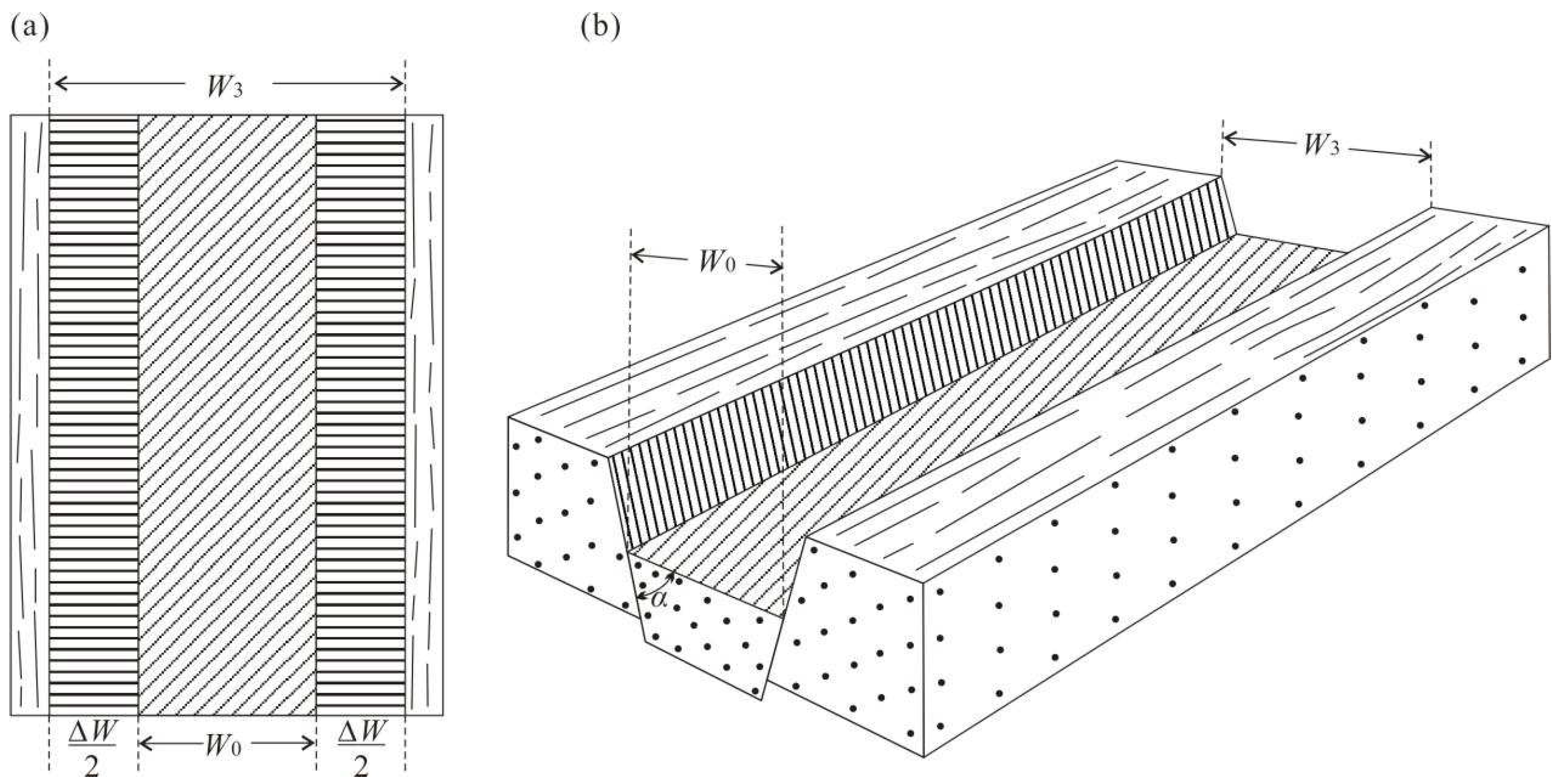
The formation of grabens results in an increase in surface area of the Moon (Figure 9). The growth of area is calculated by below equation [43,44]:
By measuring the extension caused by the displacement of related faults in the lunar graben, the area growth caused by the formation of the lunar graben can be calculated:
where ∆S is an increase in the area caused by the formation of a graben with a length of L. W0 is the widths of downthrow block (line segment EF in the Figure 3), and W3 is the widths of graben.
(W3 − W0) can be calculated by:
(W3 − W0) = 2D*cosα,
Finally, for the area growth caused by all grabens:
where α is the dip of graben-bounding fault, n is the total number of grabens.
Affected by collapse, W0 is difficult to be accurately measured. Previous studies [45] indicated that the maximum displacement (Dmax) and length (L) show a linear relation. A terrestrial fault population can be expressed using the following equation:
where γ is a constant determined by rock type and tectonic setting (Cowie and Scholz, 1992c).
Dmax = γL,
Finally, ∆S is computed by:
Using the Dmax to calculate the increase in area will result in an overestimated result. Instead, the average value of D was used for calculating γ.
The γ value of fault populations on different planets has been studied in recent years [45,46,47,48,49]. However, previous research has primarily focused on the γ of thrust faults, while there had been less studies on the γ of normal faults on terrestrial planets.
On the Earth, the γ is typically between 8 × 10⁻³ and 5 × 10⁻² over a range of tectonic settings, fault nature and rock types [45,50,51,52,53]. The γ is positively correlated with the planetary gravity [47]. Therefore, γ for the Martian fault population, as well as for Mercury thrust faults, is consistently about 5 times smaller than the Earth’s [47]. The theoretical calculation for the Moon’s γ is only 1.0 × 10⁻³ owing to the relatively lower lunar gravity [47]. However, Watters and Johnson (2010) [48] found that the γ of small-scale thrust faults is roughly 1.2 × 10⁻² based on study of lobate scarps. After measuring the geometric features of wrinkle ridges within Mare Imbrium and Mare Serenitatis, Li et al. (2018) [49] discovered that the γ of associated thrust faults within these maria were 2.13 × 10⁻² and 1.73 × 10⁻², respectively. The above research suggests that fault scale might also be an important influencing factor γ value.
The physical simulations and field investigations indicate that the D/L ratio of normal faults on Earth is also inversely correlated with fault scale [45,50]. For normal faults with length less than 200 meters, the approximate γ is 1.1 × 10⁻², and for length greater than 600 meters, the approximate γ is 8 × 10⁻³ [53]. Normal faults from the Martian northern plains, Tempe Terra and Alba Patera volcano show γ value of 1 × 10⁻³, 6.7 × 10⁻³ and 6 × 10⁻³, respectively [46,54].
It is a challenging job to measuring the γ of normal faults on terrestrial plane. The length of grabens can be measured by optical and terrain images. According to the theory, the fault displacement also can be calculated by the depth of newly formed graben. However, since the grabens have undergone degradation (e.g., collapse and filling effects) over the course of 3.6 billion years, the current depth measured through terrain data is not equivalent to the actual fault displacement.
If the measured depth is directly used to calculate the γ, the obtained result would be smaller than the actual value. In order to improve the accuracy of γ, the graben depth reduced by degradation will be estimated. Shallow depressions on the Moon are estimated to fill in at a rate of 5 ± 3 cm per million years, as derived from the analysis of boulder tracks [55]. If grabens were filled in at a rate of ~5 cm per million years, the depth of graben has decreased by ~180 m in the past 3.6 Ga. Based on the above estimations, the existing measurement depth of grabens should be increased by another 180 m.
Utilizing the depths measured from 69 profiles to directly calculate the γ yields a mean value of 2.0 × 10⁻³ (for α = 52.5°). The γ value obtained by standard linear regression method is 3.6 × 10⁻³ (y = 0.2743x + 56.042; Figure 10a). If degradation is considered and the depth will increase by 180m, the calculation results obtained by the average method and standard linear regression method are 3.8 × 10⁻³ and 3.2 × 10⁻³ (y = 0.3078x − 9.1666, R2 = 0.3568; Figure 10b), respectively. In addition, the Rupes Recta normal fault was also used to verify the results calculated from the profiles. 9 topographic profiles were carried out on this fault, yielding a γ value of 3.6 × 10⁻³. In summary, the γ value of graben-bounding normal fault on the Moon is approximately 3.6 × 10⁻³.
4.3.2. Implications for lunar thermal evolution
A total of 812 lunar incisions were identified on the 1:2,500,000-scale Lunar Geologic Map [13,14]. After further identification, 15 trenches formed by secondary impact were removed, and the remaining 797 grabens have a total length of approximately 220,000 km. The increases in area and radius are ~5671 km2 and ~130 m, respectively.
According to thermal evolution models, in the Moon’s initial approximately 1 billion years, global expansion led to an increase in radius of about 2.7 to 3.7 km, and the fastest-growing rate occurred in the first 500 million years. The accumulation of heat at the base of lunar mare regions drove the formation and ascent of magma, a process that resulted in the formation of lunar grabens [20]. Golombek (1979) [8] proposed that the lunar radius has increased by ~18 m due to the formation of the graben population. Thanks to the high-resolution images and terrain data, more lunar grabens were recognized, leading to a larger radius growth. Although our estimation suggested that the lunar radius has increased by 130 meters, this is also much smaller than the value predicted by the model. This may be because many ancient lunar grabens are completely buried and destroyed by later geological events. In addition, crater-floor fractures were also the results of lunar expansion. Only a few crater-floor fractures that are continuous with the grabens have been included in the calculation in this study. Therefore, the total radius increase caused by the formation of linear extension structures could be far more than 130 meters.
5. Conclusions
(1) Error analysis shows that various influencing factors are ultimately reflected in changes in elevation and graben width. Errors are more sensitive to changes in elevation.
(2) The the mean and the standard linear regression methods were used to calculate the dips of the graben-bounding normal faults. A dip of 39.9° was obtained by the method of standard linear regression for all data. After removing large error data, the results of 49.4° and 52.5° were derived by standard linear regression and mean methods, respectively.
(3) The D-L ratios calculated from the graben-bounding normal faults are between 2.0 × 10⁻³ and 3.8 × 10⁻³ (for α = 52.5°). The young Rupes Recta normal fault present a D-L ratio of 3.6 × 10⁻³, which is basically consistent with the results calculated from the graben-bounding normal faults by standard linear regression method. Thus, the D-L ratio of lunar normal fault is ~3.6 × 10⁻³.
(4) Based on the dip and D-L ratio of the graben-bounding normal faults, the increase in lunar radius is estimated. The radius of the Moon had expanded by approximately 130 m due to the formation of grabens.
Author Contributions
Conceptualization, K.Z. and J.L.; methodology, K.Z.; validation, G.M., D.L. and K.Z.; formal analysis, K.Z.; investigation, X.Z.; resources, K.Z. and J.L.; data curation, K.Z. and J.L.; writing—original draft preparation, K.Z.; writing—review and editing, G.M., D.L., K.Z., J.L. and X.Z.; visualization, K.Z.; project administration, K.Z. and J.L.; funding acquisition, K.Z. and J.L. All authors have read and agreed to the published version of the manuscript.
Funding
This research was funded by National Key Research and Development Program of China (Grant No. 2022YFF0503100); National Natural Science Foundation of China (Grant No. 42202264); Guizhou Provincial Science and Technology Projects (Grant NO. [QKHJC-ZK(2023)-478]); and the Key Research Program of the Chinese Academy of Sciences (Grant NO. KGFZD-145-23-15).
Data Availability Statement
The data presented in this study are available upon request from the corresponding author.
Acknowledgments
The authors thank Dr. Ke Zhang for her thoughtful suggestions which greatly helped us to improve the manuscript.
Conflicts of Interest
The authors declare no conflict of interest.
References
- Baldwin, R. The Measure of the Moon. Univ. of Chicago Press, Chicago, Illinois, 1963.
- Quaide, W. Rilles, ridges, and domes--clues to maria history. Icarus 1965, 4, 374–389. [Google Scholar] [CrossRef]
- Ouyang, Z.Y. Introduction to Lunar Science. Beijing: Chinese (in Chinese) Aerospace Press, 2005; 1–362.(in Chinese).
- Greeley, R. Lava tubes and channels in the lunar Marius Hills. Earth Moon Planets 1971, 3, 289–314. [Google Scholar] [CrossRef]
- Xiao, L.; Huang, J.; Zhao, J. W. , et al. Significance and preliminary proposal for exploring the lunar lava tubes (in Chinese). Sci Sin-Phys Mech Astron. 2018, 48, 119602. [Google Scholar] [CrossRef]
- Smith, G. A comparison of two terrestrial grabens with the lunar rilles Rima Ariadaeus and Rimae Hypatia I and II., 1966.
- McGill, G.E. Attitude of fractures bounding straight and arcuate lunar rilles. Icarus 1971, 14(1), 53–58. [Google Scholar] [CrossRef]
- Golombek, M.P. Structural analysis of lunar grabens and the shallow crustal structure of the Moon. J. geophys. Res. 1979, 84, 4657–4666. [Google Scholar] [CrossRef]
- Head, J.W. and Wilson, L. Lunar graben formation due to near-surface deformation accompanying dike emplacement. Planetary and Space Science, 1993, 41, 719–727.
- Nahm, A.L. Graben on the lunar nearside: do dikes lie beneath? Acta Geologica Sinica (English Edition), 2016, 90(S1), 175–176.
- Schultz, P.H. Floor-fractured lunar craters. The Moon 1976, 15, 241–273. [Google Scholar] [CrossRef]
- Jozwiak, L.M.; Head, J.W.; Wilson, L. Lunar floor-fractured craters as magmatic intrusions: geometry, modes of emplacement, associated tectonic and volcanic features, and implications for gravity anomalies. Icarus 2015, 248, 424–447. [Google Scholar] [CrossRef]
- Lu, T.; Zhu, K.; Chen, S.; et al. The 1:2,500,000-scale global tectonic map of the Moon. Science Bulletin 2022, 67, 1962–1966. [Google Scholar] [CrossRef]
- Ji, J.; Guo, D.; Liu, J. The 1:2,500,000-scale geologic map of the global Moon. Science Bulletin 2022, 67(15), 1544–1548. [Google Scholar] [CrossRef]
- Rubin, A.M. Dike-induced faulting and graben subsidence in volcanic rift zones. Journal of Geophysical Research 1992, 97, 1839–1858. [Google Scholar] [CrossRef]
- Rubin, A.M. Tensile fracture of rock at high confining pressure: implications for dike propagation. J. Geophys. Res. 1993, 98, 15919–15935. [Google Scholar] [CrossRef]
- Wilson, L.; Head, J.W. Tharsis-radial graben system as the surface manifestation of plume-related dike intrusion complexes—Models and implications. Journal of Geophysical Research 2002, 107, 5057. [Google Scholar] [CrossRef]
- Wilson, L.; Hawke, B.R.; Giguere, T.A.; Petrycki, E.R. An igneous origin for Rima Hyginus and Hyginus crater on the Moon. Icarus 2011, 215, 584–595. [Google Scholar] [CrossRef]
- Petrycki, J.A.; Wilson, L. Volcanic features and age relationships associated with lunar graben. Lunar and Planetary Science Conference 1999, 1335. [Google Scholar]
- Lucchitta, B.K.; Watkins, J.A. Age of graben systems on the Moon. Proc. 9th Lunar Planet. Sci. Conf. 1978, 3459–3472. [Google Scholar]
- Hiesinger, H.; Jaumann, R.; Neukum, G.; Head, J.W. Ages of mare basalts on the lunar nearside. Journal of Geophysical Research: Planets, 2000, 105(E12), 29239–29275.
- Hiesinger, H.; Head, J.W.; Wolf, U.; Jaumann, R.; Neukum, G. Ages and stratigraphy of mare basalts in Oceanus Procellarum, Mare Nubium, Mare Cognitum, and Mare Insularum. J. Geophys. Res. 2000, 108(E7), 5065. [Google Scholar] [CrossRef]
- Hiesinger, H.; Head, J.W.; Wolf, U.; Jaumann, R. Ages of lunar mare basalts in Mare Frigoris and other Nearside Maria. in XXXIV Lunar & Planetary Science Conference, 2003, 1257.
- Hiesinger, H.; Head, J.W.; Wolf, U.; Jaumann, R.; Neukum, G. New ages for basalts in Mare Fecunditatis based on crater size-frequency measurements. in XXXVII Lunar & Planetary Science Conference, 2006, 1151.
- Morota, T.; Haruyama, J.; Ohtake, M.; et al. Timing and characteristics of the latest mare eruption on the Moon. Earth and Planetary Science Letters 2011, 302(3), 255–266. [Google Scholar] [CrossRef]
- Qian, Y.; She, Z.; He, Q.; et al. Mineralogy and chronology of the young mare volcanism in the Procellarum-KREEP-Terrane. Nature Astronomy 2023, 7, 287–297. [Google Scholar] [CrossRef]
- Head, J.W.; Wilson, L. Lunar mare volcanism: Stratigraphy, eruption conditions, and evolution of secondary crust. Geochimica Et Cosmochimica Acta 1992, 56(6), 2155–2175. [Google Scholar] [CrossRef]
- Rubin, A.M.; Pollard, D.D. Origins of blade-like dikes in volcanic rift zones. Volcanism in Hawaii, USGS Proj Paper 1987, 1350, 1449–1470. [Google Scholar]
- Scott, R.; Wilson, L. The stress state of the lunar lithosphere and the volumes of intruded and erupted magmas. 32nd Annual Lunar and Planetary Science Conference 2001, 1549. [Google Scholar]
- Anderson, E.M. The Dynamics of Faulting, 2nd ed., 206 pp., Oliver and Boyd, London, 1951.
- Solomon, S.C. The relationship between crustal tectonics and internal evolution in the Moon and Mercury. Physics of the Earth and Planetary Interiors, 1977, 15(2–3), 135–145.
- Solomon, S.C.; Chaiken, J. Thermal expansion and thermal stress in the moon and terrestrial planets: Clues to early thermal history. Proc. Lunar Sci. Conf. 7th 1976, 3229–3243. [Google Scholar]
- Barker, M.K.; Mazarico, E.; Neumann, G.A.; Zuber, M.T.; Haruyama, J.; Smith, D. E. A new lunar digital elevation model from the Lunar Orbiter Laser Altimeter and SELENE Terrain Camera. Icarus 2016, 273, 346–355. [Google Scholar] [CrossRef]
- Handin, J. Strength and ductility. Handbook of Physical Constants, Geol. Soc. Amer. Mem. 1966, 97, 223–289. [Google Scholar]
- Handin, J.; Hager, Jr., R. V. Experimental deformation of sedimentary rocks under confining pressure: Tests at room temperature on dry samples. Amer. Ass. Petrol. Geol. Bull. 1957, 41, 1–50. [Google Scholar]
- Handin, J.; Hager, Jr., R. V. Experimental deformation of sedimentary rocks under confining pressure: Tests at high temperature. Amer. Ass. Petrol. Geol. Bull. 1958, 42, 2892–2934. [Google Scholar]
- Nahm, A.L.; Schultz, R. A. Rupes Recta and the geological history of the Mare Nubium region of the Moon: Insights from forward mechanical modelling of the “Straight Wall,”. Volcanism and Tectonism Across the Inner Solar System. Geological Society of London Special Publication 2015, 401, 377–394. [Google Scholar] [CrossRef]
- Pollard, D.D.; Segall, P. Theoretical displacements and stresses near fractures in rock: With applications to faults, joints, veins, dikes, and solution surfaces, in Fracture Mechanics of Rock, edited by B. K. Atkinson, Academic, San Diego, Calif., U. S., 1987; pp. 277–350.
- Walsh, J.J.; Waterson, J. Analysis of the relationship between displacements and dimensions of faults. J. Struct. Geol. 1988, 10, 239–247. [Google Scholar] [CrossRef]
- Cowie, P.A.; Scholz, C.H. Physical explanation for displacement-length relationship for faults using a post-yield fracture mechanics model. J. Struct. Geol. 1992, 14, 1133–1148. [Google Scholar] [CrossRef]
- Cowie, P.A.; Scholz, C.H. Growth of faults by accumulation of seismic slip. J. Geophys. Res. 1992, 97, 11085–11096. [Google Scholar] [CrossRef]
- Burgmann, R.; Pollard, D.D.; Martel, S.J. Slip distributions on faults: Effects of stress gradients, inelastic deformation, heterogeneous host-rock stiffness, and fault interaction. J. Struct. Geol. 1994, 16, 1675–1690. [Google Scholar] [CrossRef]
- Scholz, C.H.; Cowie, P.A. Determination of geologic strain from fault slip data. Nature 1990, 346, 837–839. [Google Scholar] [CrossRef]
- Cowie, P.A.; Scholz, C.H.; Edwards, M.; Malinverno, A. Fault strain and seismic coupling on mid-ocean ridges. J. Geophys. Res. 1993, 98, 17911–17920. [Google Scholar] [CrossRef]
- Cowie, P.A.; Scholz, C.H. Displacement-length scaling relationship for faults: data synthesis and discussion. J. Struct. Geol. 1992, 14(10), 1149–1156. [Google Scholar] [CrossRef]
- Wilkins, S.J.; Schultz, R.A.; Anderson, R.C.; Dohm, J.M.; Dawers, N.H. Deformation rates from faulting at the Tempe Terra extensional province. Mars. Geophys. Res. Lett. 2002, 29(18), 1884. [Google Scholar] [CrossRef]
- Schultz, R. A.; Okubo, C. H.; Wilkins, S. J. Displacement-length scaling relations for faults on the terrestrial planets. Journal of Structural Geology 2006, 28(12), 2182–2193. [Google Scholar] [CrossRef]
- Watters, T.R.; Johnson, C.L. Lunar tectonics, In Planetary Tectonics, Watters, T.R., Schultz, R.A., Eds.; Publisher: Cambridge Univ. Press, Cambridge, U. K, 2010; pp. 121–182. [Google Scholar]
- Li, B.; Ling, Z.; Zhang, J.; Chen, J.; Ni, Y.; Liu, C. Displacement-length ratios and contractional strains of lunar wrinkle ridges in mare serenitatis and mare tranquillitatis. Journal of Structural Geology 2018, 109(APR.), 27–37. [Google Scholar] [CrossRef]
- Dawers, N.H.; Anders, M.H. Displacement-length scaling and fault linkage. J. Struct. Geol. 1995, 17, 607–614. [Google Scholar] [CrossRef]
- Clark, R.; Cox, S. A modern regression approach to determining fault displacementlength scaling relationships. J. Struct. Geol. 1996, 18, 147–154. [Google Scholar] [CrossRef]
- Schultz, R.A.; Fossen, H. Displacement-length scaling in three dimensions: the importance of aspect ratio and application to deformation bands. J. Struct. Geol. 2002, 24, 1389–1411. [Google Scholar] [CrossRef]
- Dong, J.; Zhang, S.H.; Jiang, Y.B. The displacement-length relationship of faults and its significance. Earth Science Frontiers. 2004, 11(4), 575–584. (in Chinese)
- Polit, A.T.; Schultz, R.A.; Soliva, R. Geometry, displacement-length scaling, and extensional strain of normal faults on mars with inferences on mechanical stratigraphy of the martian crust. J. Struct. Geol. 2009, 31(7), 662–673. [Google Scholar] [CrossRef]
- Arvidson, R.; Drozd, R.J.; Hohenberg, C.M.; Morgan, C.J.; Poupeau, G. Horizontal transport of the regolith, modification of features, and erosion rates on the lunar surface. Moon 1975, 13, 67–79. [Google Scholar] [CrossRef]
Figure 1.
Lunar Reconnaissance Orbiter (LRO) Wide Angle Camera (WAC) images of grabens (a,b), rilles (c) and crater-floor fractures (d).
Figure 1.
Lunar Reconnaissance Orbiter (LRO) Wide Angle Camera (WAC) images of grabens (a,b), rilles (c) and crater-floor fractures (d).
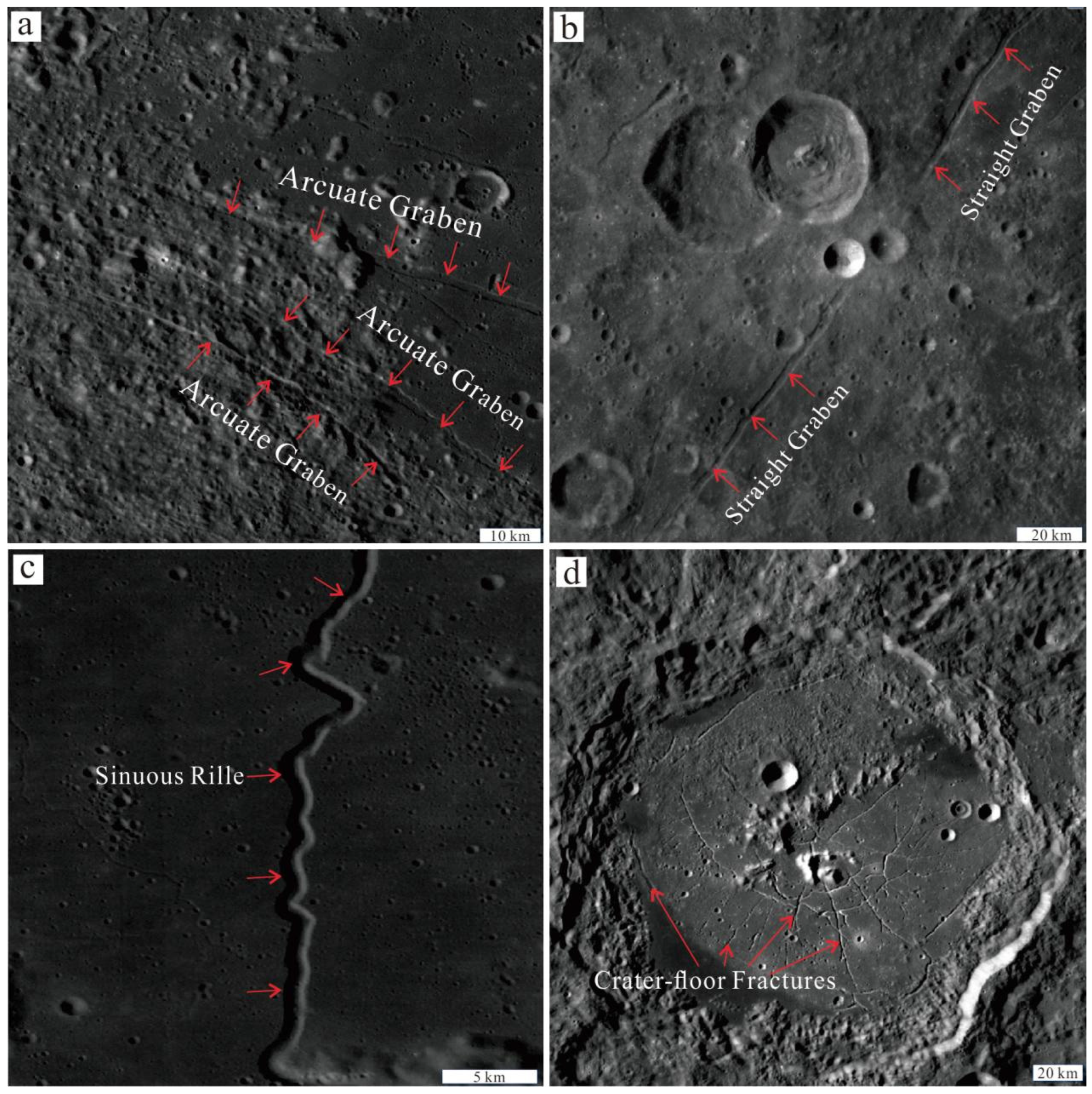
Figure 2.
Distribution of lunar grabens. The base image is WAC image.
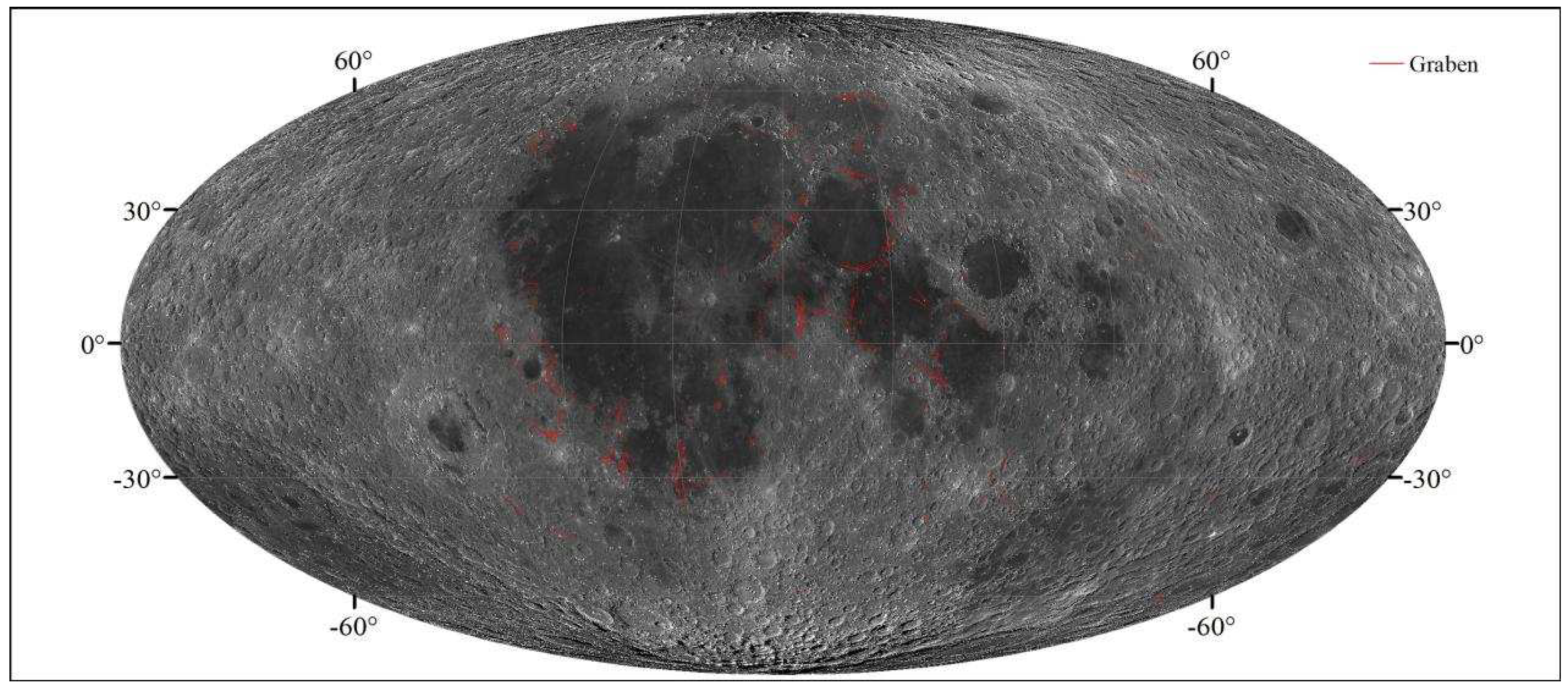
Figure 3.
WAC image and block sketch of a lunar graben showing dependence of width on elevation; α may be calculated using Equation (1). Figure 3b is modified from [7].

Figure 4.
Topographic and slope profiles at the topographic high (a,c) and low (b,d) position.
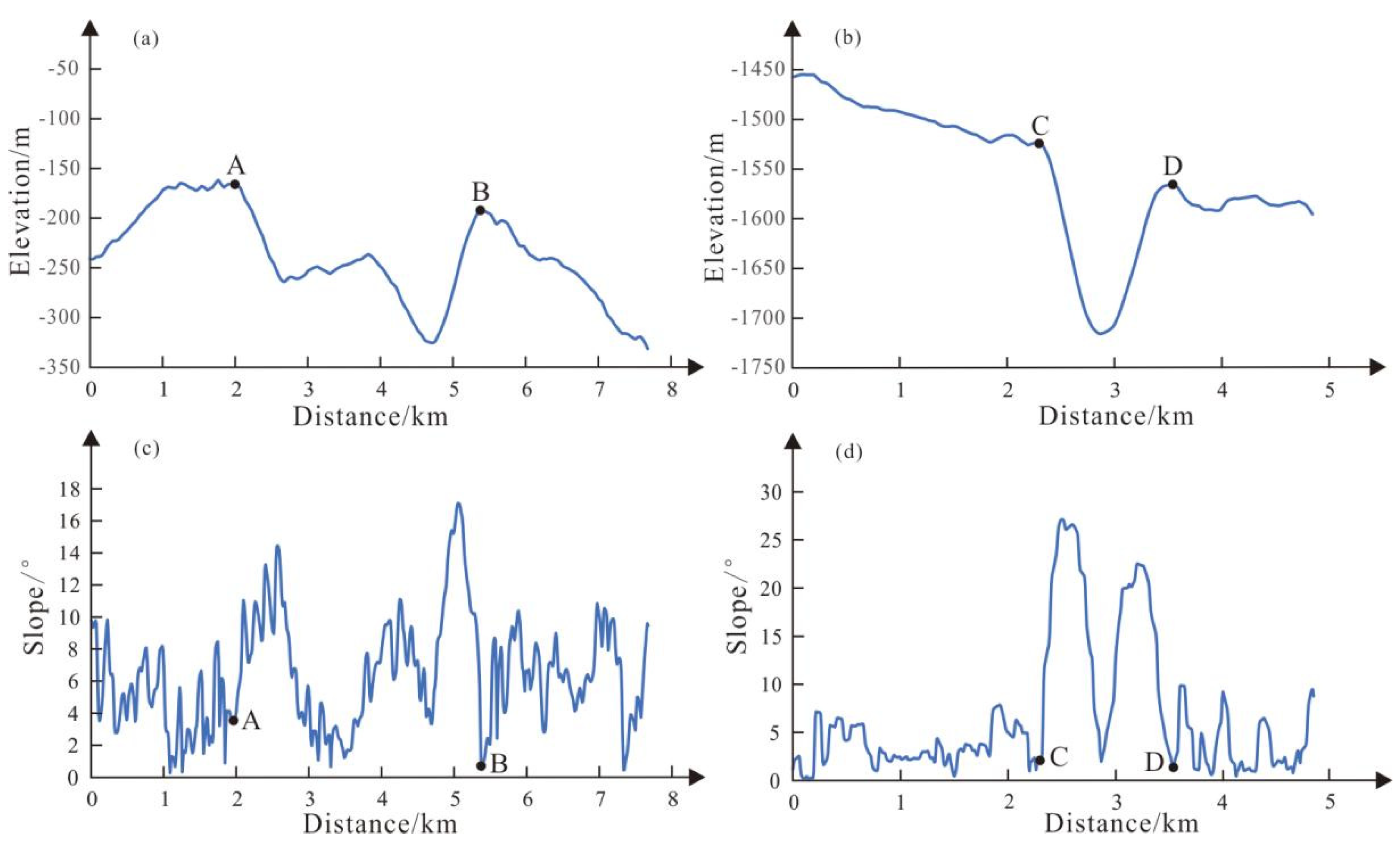
Figure 5.
Topographic and slope profiles at the topographic high (a,c) and low (b,d) position.
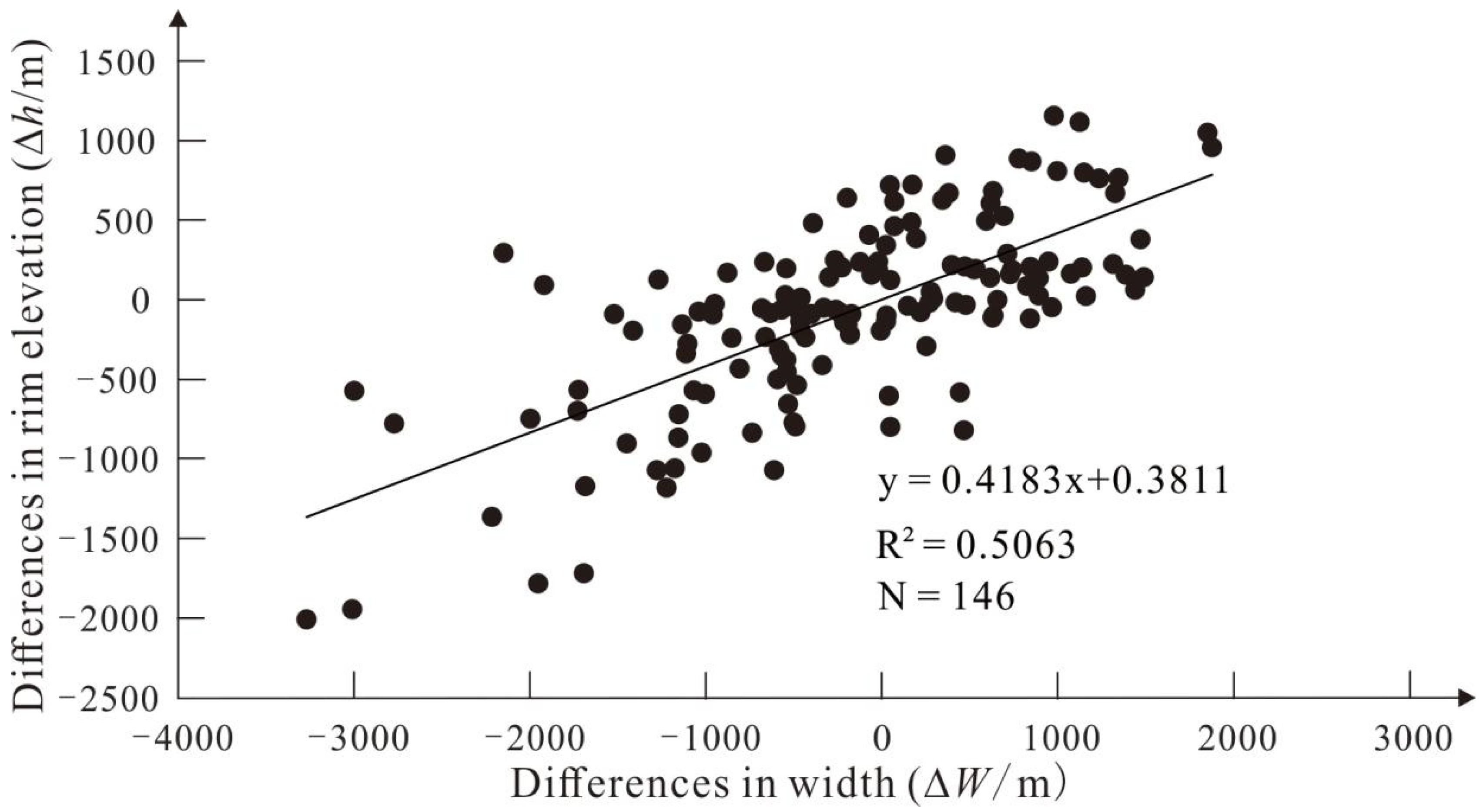
Figure 6.
Topographic and slope profiles at the edge (profile 1) and middle (profile 2) of the Rupes Recta fault.
Figure 6.
Topographic and slope profiles at the edge (profile 1) and middle (profile 2) of the Rupes Recta fault.
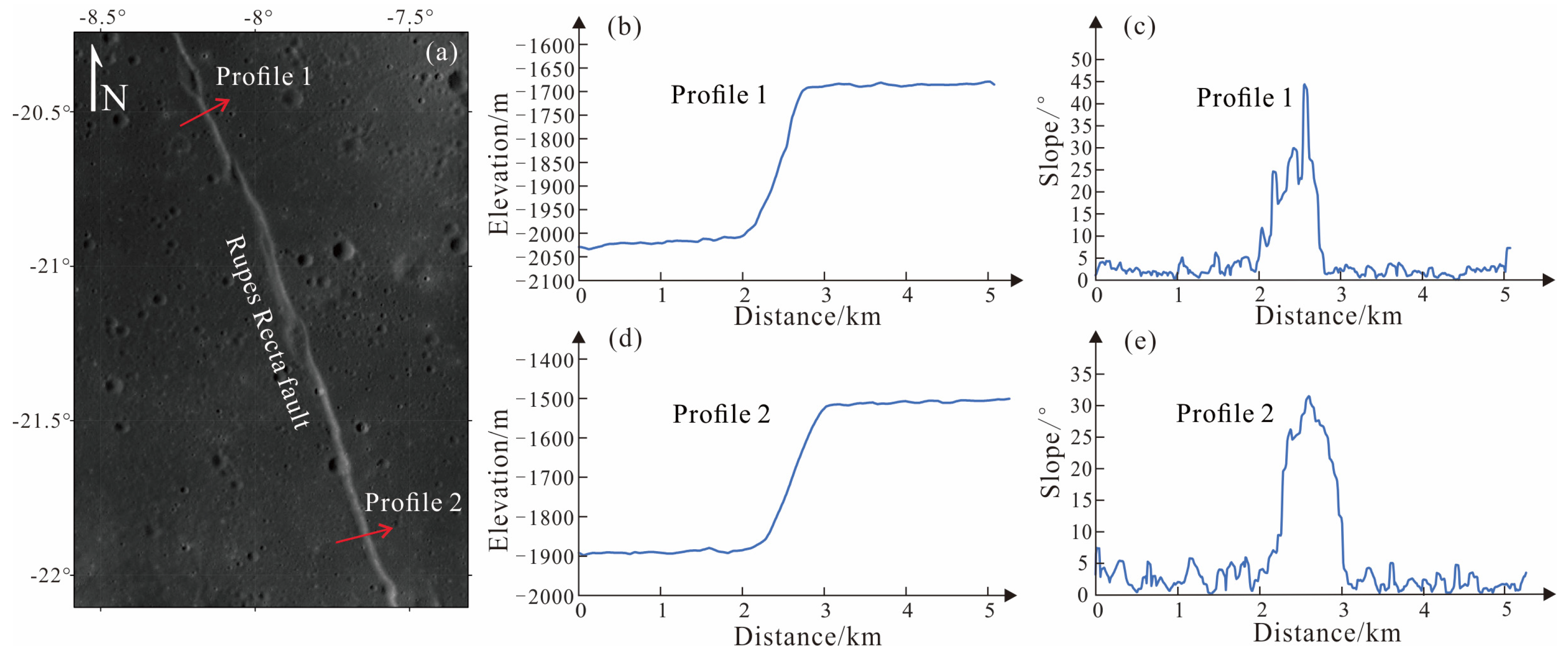
Figure 7.
Statistics of dips that calculated from ∆h < 200 m data.
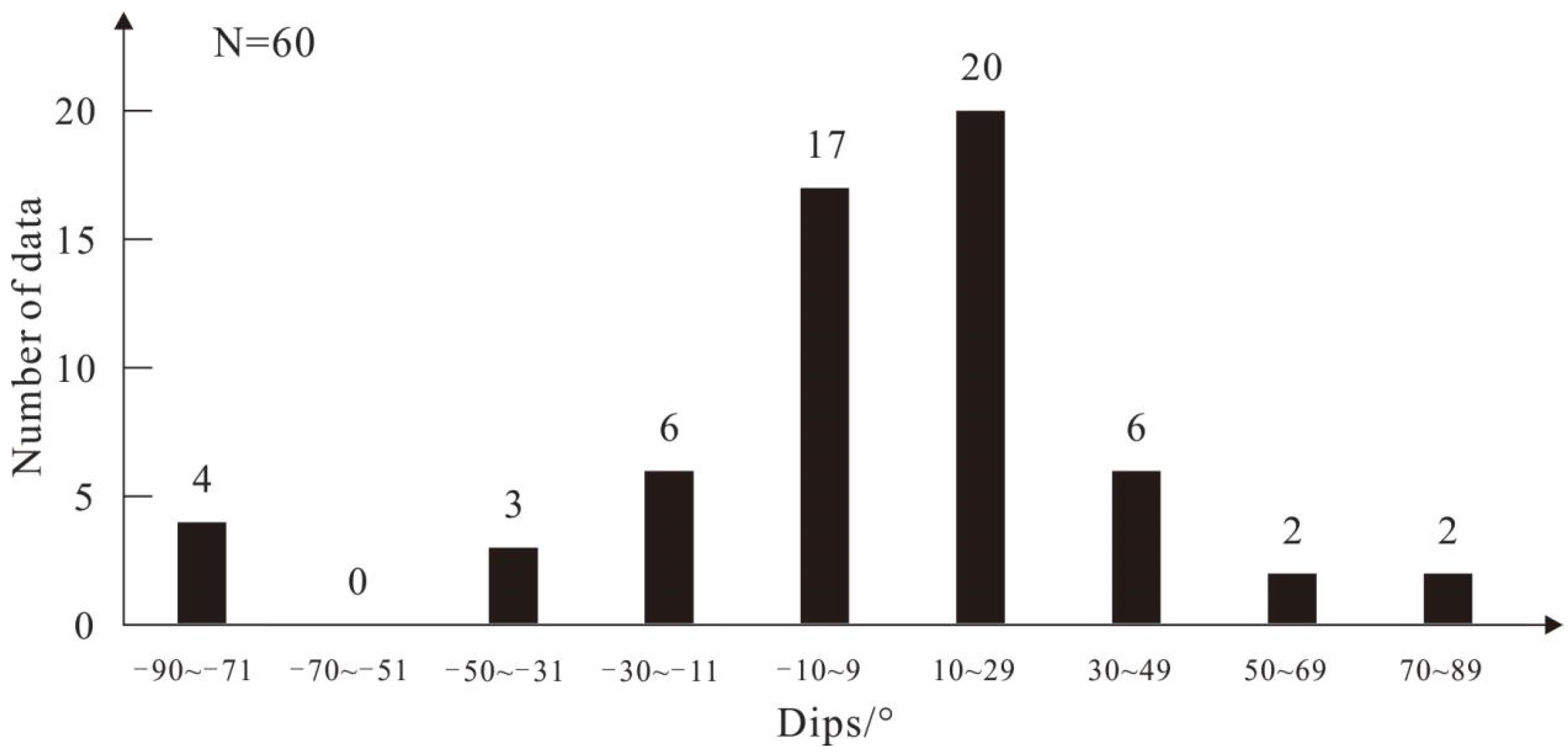
Figure 8.
∆W versus ∆h plots after removing ∆h < 200 m data (a) and negative values (b).
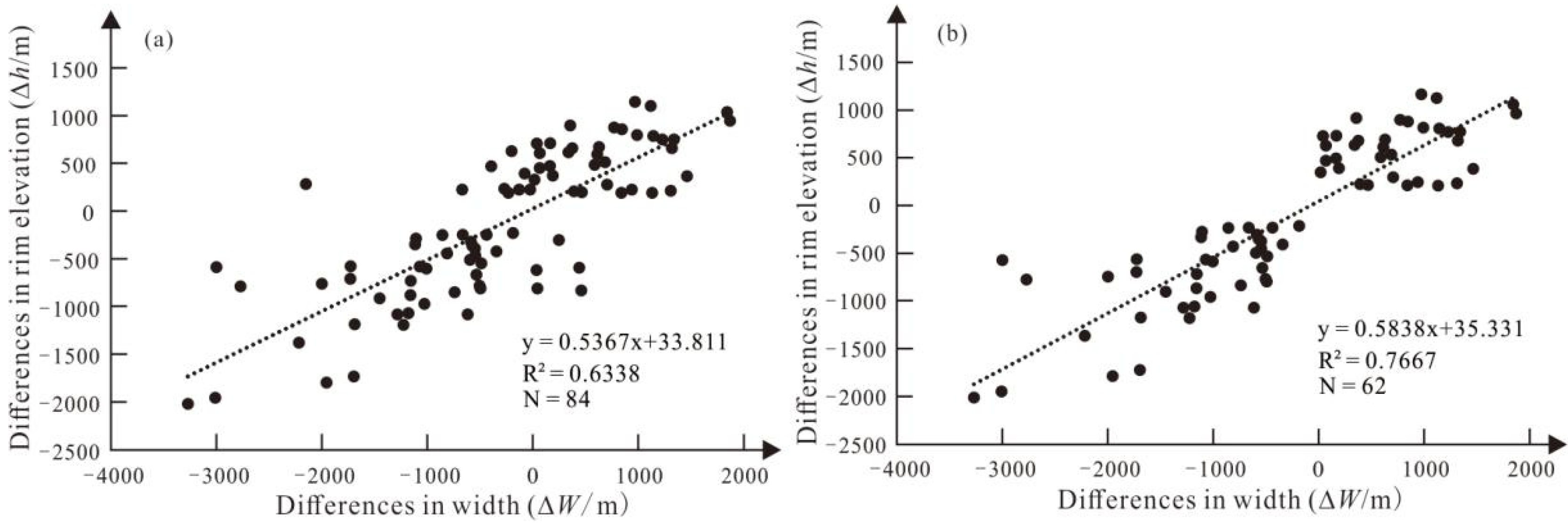
Figure 9.
Vertical view (a) and sectional drawing (b) of a lunar graben.
Figure 10.
The D-L plot of grabens. The D values in the (a) are calculated from depths, and the D values in the (b) include the depth reduction caused by degradation. The Graben Hippalus is split into two independent grabens for the purpose of the calculation. Therefore, 18 sets of data were obtained from 17 grabens.

Table 1.
Information of the selected 17 grabens.
| No. | Graben Name | Location | Length/km | Number of Profiles | Number of calculation results | Dips/° | |
|---|---|---|---|---|---|---|---|
| Starting (X, Y) |
End (X, Y) |
||||||
| 1 | / | -67.33, 2.45 | -64.74, -0.19 | 111 | 6 | 15 | 46.4 |
| 2 | / | -74.00, -2.98 | -72.78, -5.60 | 87 | 4 | 6 | 47.8 |
| 3 | / | -78.29, 4.58 | -76.42, 2.81 | 76 | 3 | 3 | 4.0 |
| 4 | Gerard | -84.608, 49.4585 | -85.89, 47.12 | 79 | 6 | 15 | 61.6 |
| 5 | Repsold | -82.72, 50.34 | -77.14, 51.88 | 159 | 8 | 28 | 52.3 |
| 6 | Sirsalis | -61.99, -16.19 | -66.05, -20.97 | 184 | 8 | 28 | 41.5 |
| 7 | de Gasparis | -48.32, -23.00 | -50.69, -25.86 | 109 | 3 | 3 | 16.1 |
| 8 | / | -50.98, -25.64 | -48.76, -27.94 | 92 | 4 | 6 | 45.4 |
| 9 | / | -46.78, -26.13 | -47.82, -29.10 | 96 | 3 | 3 | -2.4 |
| 10 | Hippalus-1 | -30.20, -22.22 | -33.44, -29.24 | 245 | 3 | 3 | 26.6 |
| 11 | Hippalus-2 | -29.43, -25.69 | -31.14, -28.60 | 99 | 2 | 1 | 3.3 |
| 12 | Hippalus-3 | -28.55, -23.57 | -28.77, -26.16 | 95 | 2 | 1 | -3 |
| 13 | Hesiodus | -27.53, -32.40 | -17.16, -28.94 | 279 | 6 | 15 | 13.3 |
| 14 | / | 9.62, 7.65 | 14.41, 6.08 | 136 | 5 | 10 | 34.6 |
| 15 | Goclenius-1 | 41.39, -6.40 | 43.88, -9.01 | 103 | 3 | 3 | 21.8 |
| 16 | Goclenius-2 | 43.89, -9.11 | 45.22, -10.43 | 53 | 3 | 3 | 61.5 |
| 17 | / | 30.36, 30.24 | 29.96, 27.49 | 84 | 3 | 3 | 68.5 |
| Total | 69 | 146 | |||||
| Mean | 41.3 | ||||||
Disclaimer/Publisher’s Note: The statements, opinions and data contained in all publications are solely those of the individual author(s) and contributor(s) and not of MDPI and/or the editor(s). MDPI and/or the editor(s) disclaim responsibility for any injury to people or property resulting from any ideas, methods, instructions or products referred to in the content. |
© 2023 by the authors. Licensee MDPI, Basel, Switzerland. This article is an open access article distributed under the terms and conditions of the Creative Commons Attribution (CC BY) license (http://creativecommons.org/licenses/by/4.0/).
Copyright: This open access article is published under a Creative Commons CC BY 4.0 license, which permit the free download, distribution, and reuse, provided that the author and preprint are cited in any reuse.


