1. Introduction
Using welding as the main joined way, ship and offshore engineering structures are prone to fatigue failure in welded areas during service because of residual stresses generated by welding. Meanwhile, due to the artificial factors and complexity of welding, welded joints inevitably contain initial defects (inclusion, porosity, undercut, lack of penetration, etc.), and cracks are prone to initiation and growth under cyclic loadings in such zones [
1]. The fracture mechanics can be used to study the fatigue life of defective structures, which is considered suitable for assessing fatigue strength. Generally, the residual stress intensity factor
Kres is used to quantify the effect of welding residual stress (WRS) on crack propagation behaviour and is considered in calculating the effective stress intensity factor range
Keff. Currently, there are two mainstream methods for the calculation of
Kres: the weight function method (WFM) and the finite element method (FEM). The WFM can calculate
Kres quickly based on the assumption of linear elasticity. At the same time, FEM can consider the effect of the material‘s plasticity, as a result of which it can obtain more accurate results.
Most studies have ignored the influence of WRS re-distribution, leading to the deviation between prediction and actual crack propagation behaviour in the areas containing WRS [
2]. WRS re-distribution behaviour results from the structure’s remaining ligament reduction during crack growth. Scholars have done plenty of work to investigate the re-distribution behaviour of WRS. Servetti and Zhang [
3] calculated the stress intensity factor (SIF) of MT specimens by virtual crack technique with the static simulation of crack propagation in 0.5 mm increments of crack length. Barsoum and Barsoum [
4] calculated the
Keff of a T-shaped welded joint under the influence of WRS re-distribution by 2D finite element method. Lee et al. [
5] analyzed the variation of WRS during crack propagation and found that the results were more accurate when considering the re-distribution behaviour. Terada [
6] proposed the WRS re-distribution rule for butt welding based on the superposition principle and ideal residual stress distribution rule, which were in good agreement with experimental results. Xu [
7] studied the crack propagation behaviour of the butt-welded plate and found that the WRS was constantly released during crack propagation, with a decreasing impact on the crack propagation behaviour.
The above scholars studied WRS re-distribution behaviour during crack propagation using the linear elastic fracture mechanics (LEFM) method and proposed some simplified approaches. However, the crack tip material yields due to the high-stress concentration during the crack propagation process, and plastic strain will lead to further changes in areas containing WRS. Some studies have shown that the effect of plastic strain on WRS re-distribution at the crack tip is essential. Literature [
8,
9,
10] monitored WRS re-distribution behaviours of MT and compact tension (CT) specimens by neutron diffraction technique and pointed out that neglecting the effect of plasticity would obtain inaccurate results. Wang and Qian [
11] measured the residual stress of welded specimens, indicating that WRS relaxation depends on stress re-distribution caused by plastic deformation and the plastic re-distribution behaviour is affected by loading ratios.
This investigation investigates the plastic re-distribution behaviour of areas containing WRS and its effect on crack propagation behaviour. This study uses experimental and simulation studies of WRS re-distribution behaviour during fatigue crack propagation. The whole investigation is organized as follows:
Section 2 introduces the crack propagation experiment of MT specimens and the theoretical calculation method of residual stress re-distribution. Deviations between experimental data and theoretical predictions are discussed. In
Section 3, an elastic-plastic crack propagation simulation procedure of residual stress’s plastic re-distribution behaviour is proposed, and the comparison between experimental and simulation results is conducted to verify the accuracy and effectiveness of the proposed simulation method.
Section 4 discusses the relation between Kres and stress ratio R based on elastic-plastic simulation results. Finally, this study presented a polynomial prediction model to describe
Kres by loading ratio R and crack size a/W. All conclusions are drawn in
Section 5.
2. Experimental procedure
A series of crack propagation experiments were carried out to establish an actual reference of crack propagation and the re-distribution behaviour of WRS. Details of the experiments are described in the following content.
2.1. Material and main dimensions of specimens
The material of specimens used in the experiments is Ni-Cr-Mo-V high-strength marine steel used for large ships and offshore structures.
Table 1 lists the parameters of the Chaboche combined hardening model obtained through material experiments at room temperature.
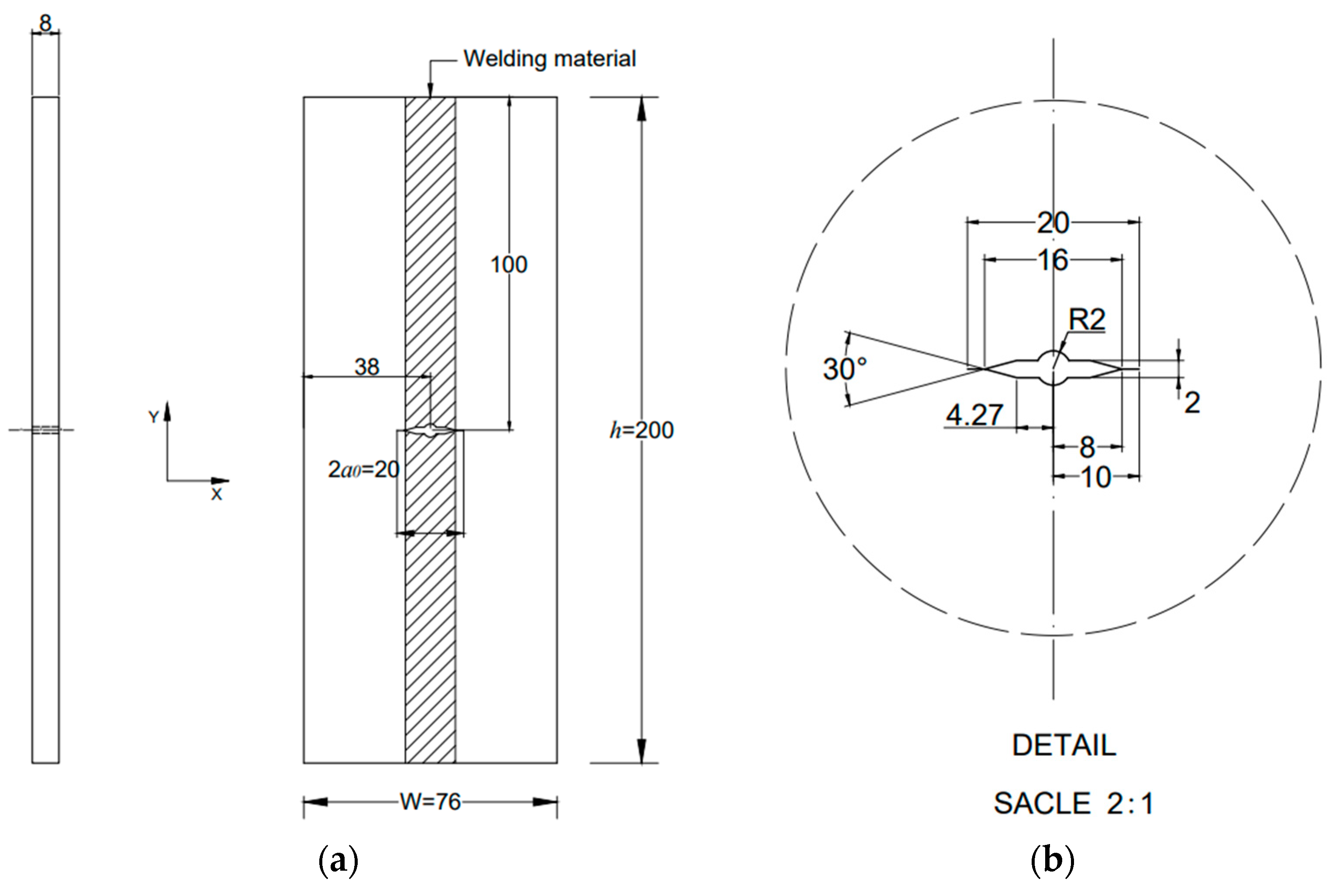
MT-shape specimens were used to represent a classical butt-welded form, as shown in
Figure 1. All specimens were manufactured in several 300×300×12mm butt-welded square plates from the same Ni-Cr-Mo-V steel plate. The welding process used a flat butt submerged-arc technique with a Y-shaped bevel, and welding speed was controlled at 30-40cm/min. The final average welded width is around 14mm. As shown in
Figure 1, the MT specimen was fabricated by laser cutting.
Meanwhile, a 2mm pre-crack was cut by a 0.12mm molybdenum wire according to ASTM E647 [
12]. It should be noted that this study only focused on the residual fatigue strength and crack propagation behaviour in the base material of MT specimens. Those behaviours in the welded area were not investigated.
2.2. Test setup
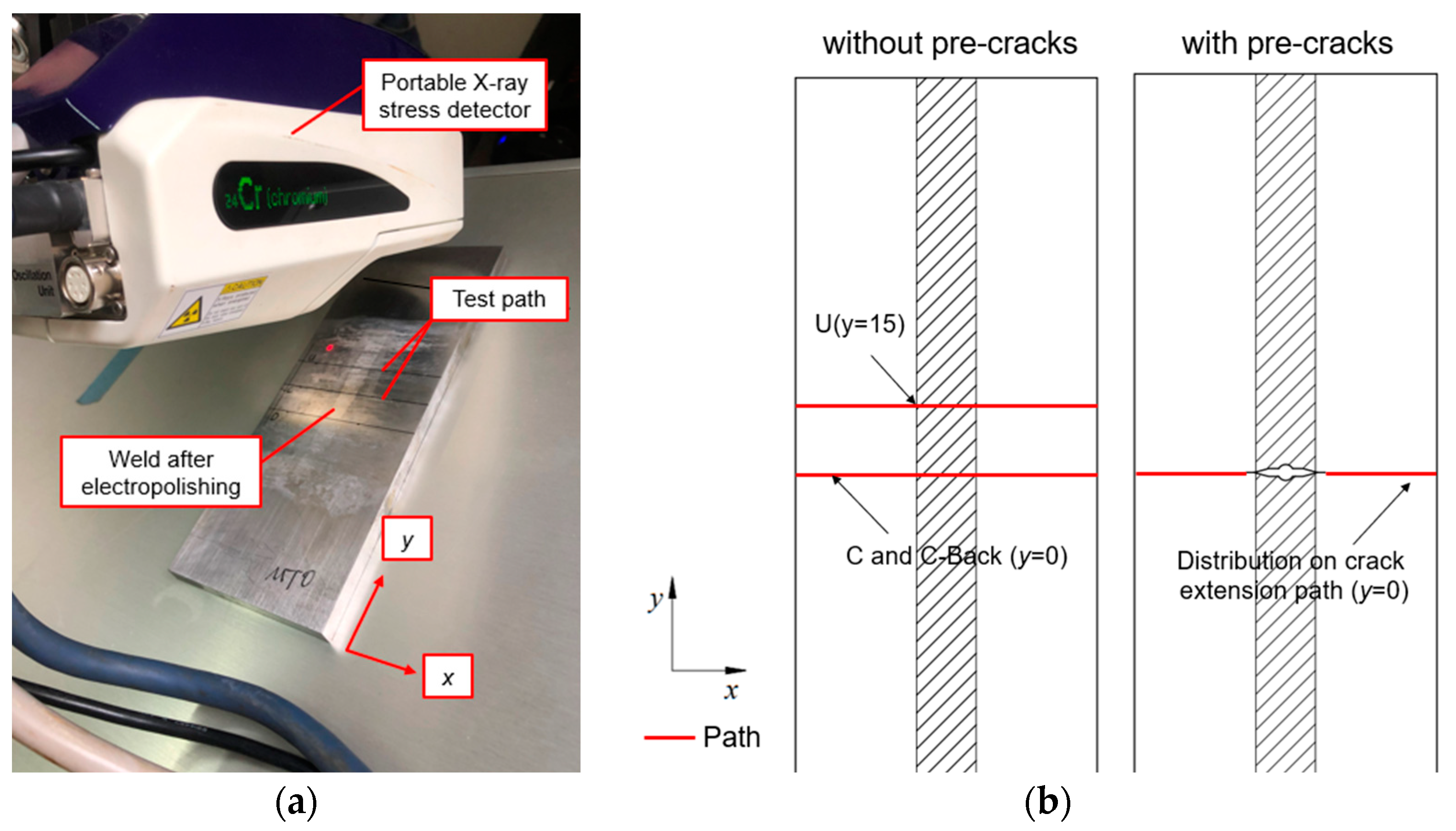
At the beginning of the fatigue experiment, the initial WRS of MT specimens was measured non-destructively by a portable X-ray stress detector, as shown in
Figure 2. Due to the constraint of the X-ray method, all measured data are initial stress states of MT specimens’ surfaces. Only longitudinal (y-direction) WRS distributions are concerned in the measurement, mainly contributing to crack opening. Moreover, the measured path is set along the crack propagation direction (
x-direction). Each point located far away from the welded zone has a 5mm spacing, and spacing between other points near the weld is appropriately closer.
To investigate the influence of initial defect and butt welding on initial WRS, the following three types of MT specimens were designed and manufactured: (a) butt specimen without pre-cracks, (b) butt specimen with pre-cracks and (c) non-welded base material specimen with pre-cracks. For the butt specimen without pre-cracks, initial residual stresses were measured at three paths: centre line C (
y = 0), upper line U (
y = 15), and back-centre line C-Back (
yB = 0). For butt specimens with pre-cracks, only longitudinal residual stress distribution on the crack extension line was measured. The measurement paths and local coordinate systems on the specimen are illustrated in
Figure 2. Residual stress data will be presented in the following
Section 2.3.1.
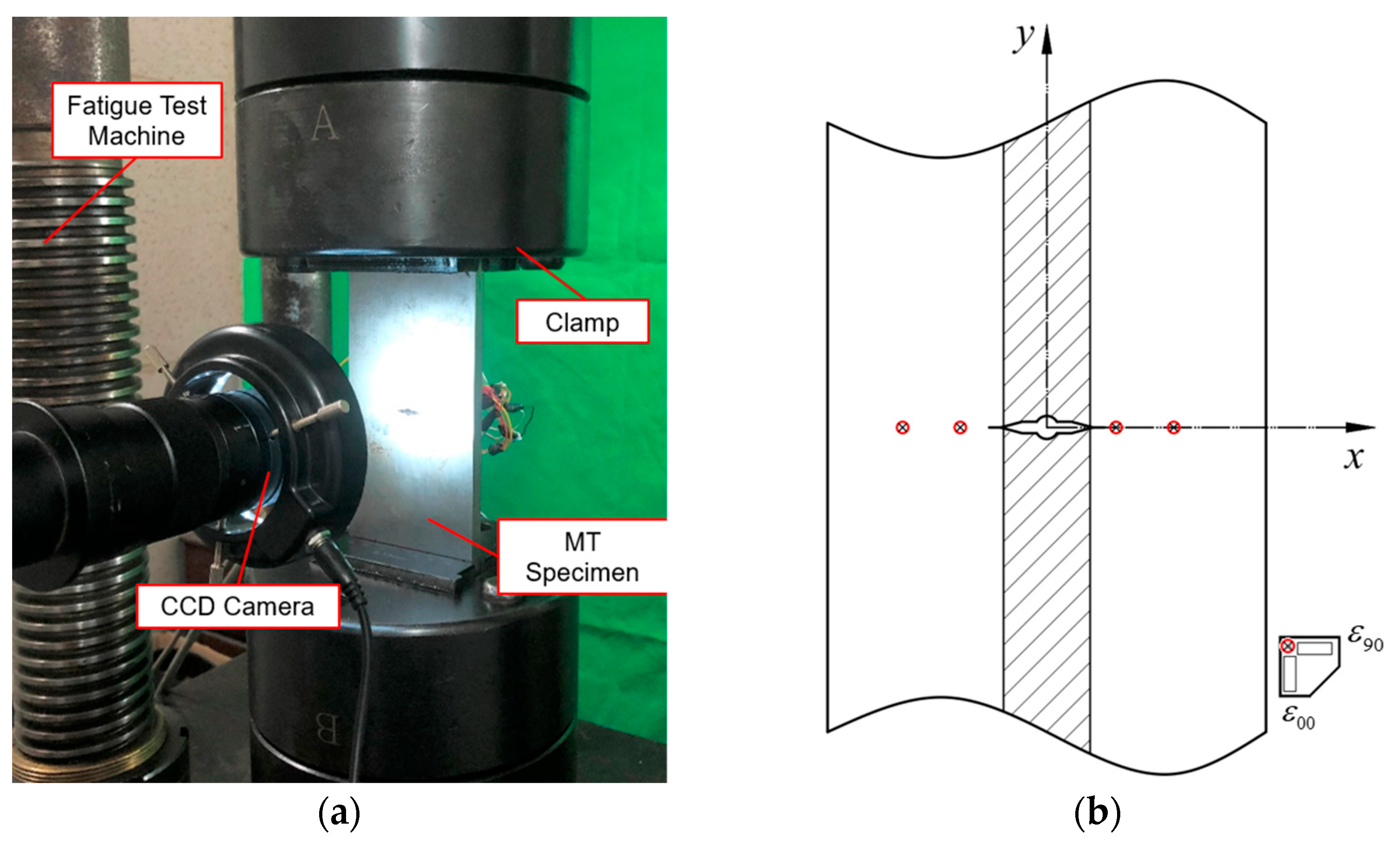
A series of fatigue crack propagation experiments on MT specimens were carried out to investigate crack propagation behaviour with an initial residual stress field obtained. All MT specimens were tested at room temperature in the JXG-200 high-frequency fatigue test machine with a maximum loading capacity of
300kN. The applied load form is a sine wave applied along the weld direction. All loading conditions are listed in
Table 2. The test machine’s counterweight and the specimen’s stiffness determined the loading frequency. During the experiment, the loading frequency was about 160 Hz when loading began and gradually decreased with the crack propagation.
MT specimens were assembled, as shown in
Figure 3. The actuator and clamp were aligned with the longitudinal central line of specimens before loading. During the experiment, strain gauges were used to monitor the change of residual strain along crack propagation, which were located at x=-25, -15, 12, and 22mm, respectively. The loading was decreased to zero when data was collected. It should be noted that these operations may have a potential variable amplitude effect on crack propagation behaviour and plastic zone at the crack tip, which is not concerned in the current study. A CCD camera measured the crack length, and loading cycles were recorded by computer.
2.3. Experimental results and discussion
2.3.1. Distribution of initial welding residual stress
The measurement results of longitudinal initial WRS
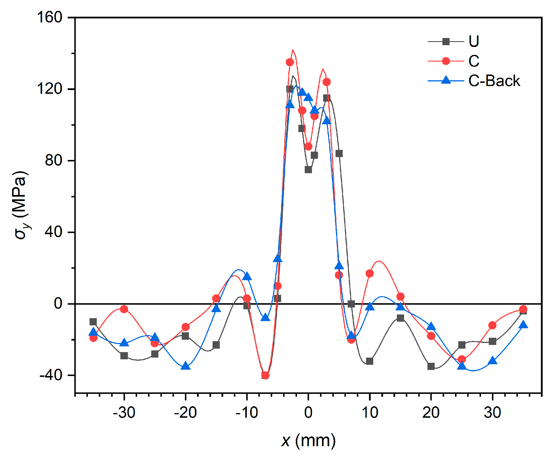
σy for all specimens are given in this section. Firstly, the difference in the longitudinal initial WRS distribution of measurement paths of butt specimens without pre-cracks is discussed, as shown in
Figure 4. It can be seen that the positions where the tension-compression stress converts or reaches peak value are close with the deviation of initial WRS results of each measurement path being kept within 20MPa. This phenomenon indicates that the stress distribution of WRS on the upper and lower surfaces is similar.
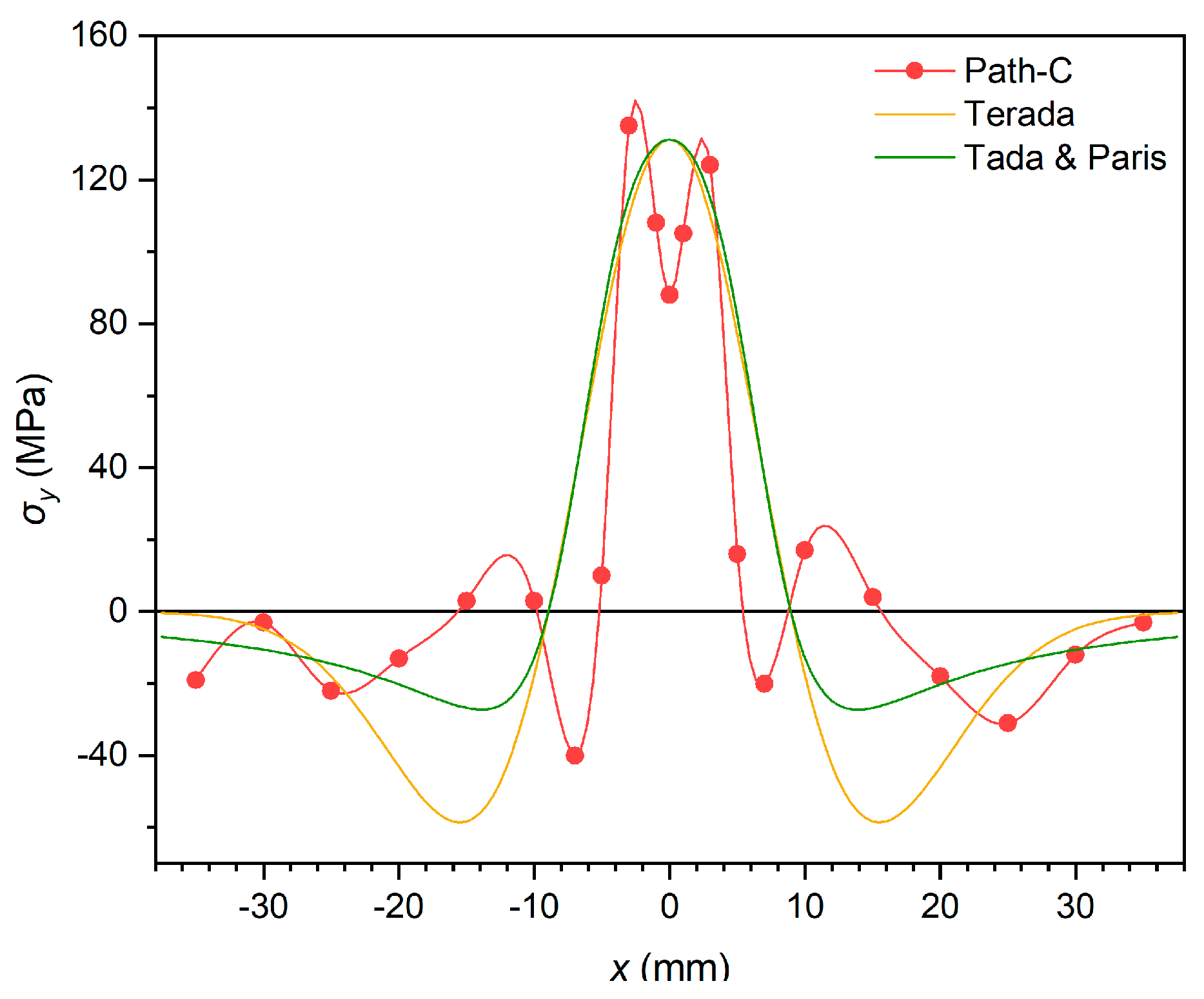
Then two distribution function models were adopted: the Terada distribution function [
13], as shown in Eq. (1) and the Tada &Paris distribution function [
14], as shown in Eq. (2), to compare with the measured results (Path-C), as shown in
Figure 5.
where
x is the
x-coordinate value shown in
Figure 3,
σy,0=131MPa and
c =8.94 are the initial WRS distribution parameters obtained from X-ray measurement results.
As illustrated in
Figure 5, measured data shows an obvious bimodal feature. Stress in the centre of the weld is lower than on two sides due to the annealing operation after the last welding. In contrast, distribution functions predict an unimodal distribution, unlike test data. At the edge of the specimen far away from the weld (where
x≥25mm),
σy decreases to 0, and there is no significant difference between distribution functions and test data.
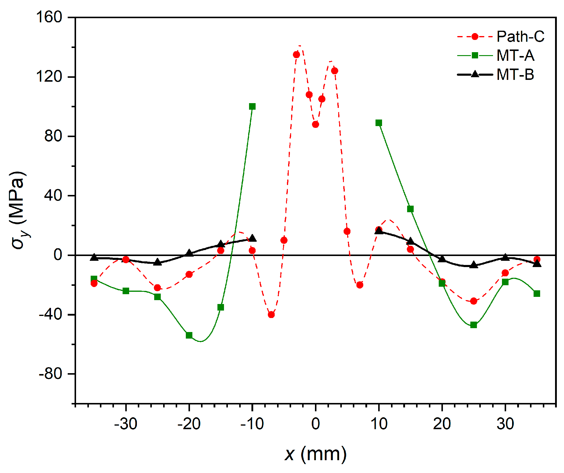
The initial WRS of three types of specimens was compared in
Figure 6. Compared with the butt specimen without pre-cracks (Path-C), the longitudinal WRS near the crack tip (
x = ± 10mm) of the butt specimen with pre-cracks (MT-A) increases dramatically from 20MPa to 60-120MPa with the appearance of a crack. This is because when materials at the centre of the specimen are removed, WRS needs to be balanced on the residual ligament of the specimen. Additionally, in the area far from the crack tip (
x = ± 25mm), the residual compressive peak stress also increases to balance residual tensile stress near the crack tip. This phenomenon indicates that the WRS re-distribution caused by the crack length change cannot be ignored. As for the initial WRS of non-welded base material specimens with pre-cracks (MT-B), measured data are much closer to zero than MT-A.
2.3.2. Welding residual stress re-distribution calculation
Terada proposed the following rule as a theoretical solution to predict the WRS re-distribution behaviour of butt-welded specimens:
where
σy(x) is the initial longitudinal WRS value calculated by Eq. (2),
σy, re(x) is the longitudinal WRS re-distribution value, and a is the current crack length. It should be noted that both Eq. (1)and Eq. (3) are named as Terada rules, Eq. (1) is used to describe the distribution of the initial WRS and Eq. (3) is used to describe the re-distribution of the WRS. To simplify the calculation, Terada [
6] proposed a numerical integration approximation method:
and
where
n=30 is the numerical discretization parameter.
Terada rule can predict the re-distribution behaviour of WRS when the initial distribution is determined. However, due to the singularity of integral multiplier a/π(x2-a2)1/2 at the crack tip, the accuracy of the Terada rule is not satisfying near the crack tip.
On the other hand, the experimental method is also an important means to research the re-distribution behaviour of fatigue crack propagation. The experimental method is based on the measurement results of bidirectional strain gauges, and generalized Hooke’s law can derive the variation of residual stress Δσ
y on the crack extension line:
where (
) and (
) are the bidirectional strain gauge readings of measuring points on the crack extension line before and after crack propagation. The subscript “00” represents the direction parallel to the weld, and “90” represents the direction perpendicular to the weld.
E and
ν are Young’s modulus and Poisson’s ratio of the material, respectively.
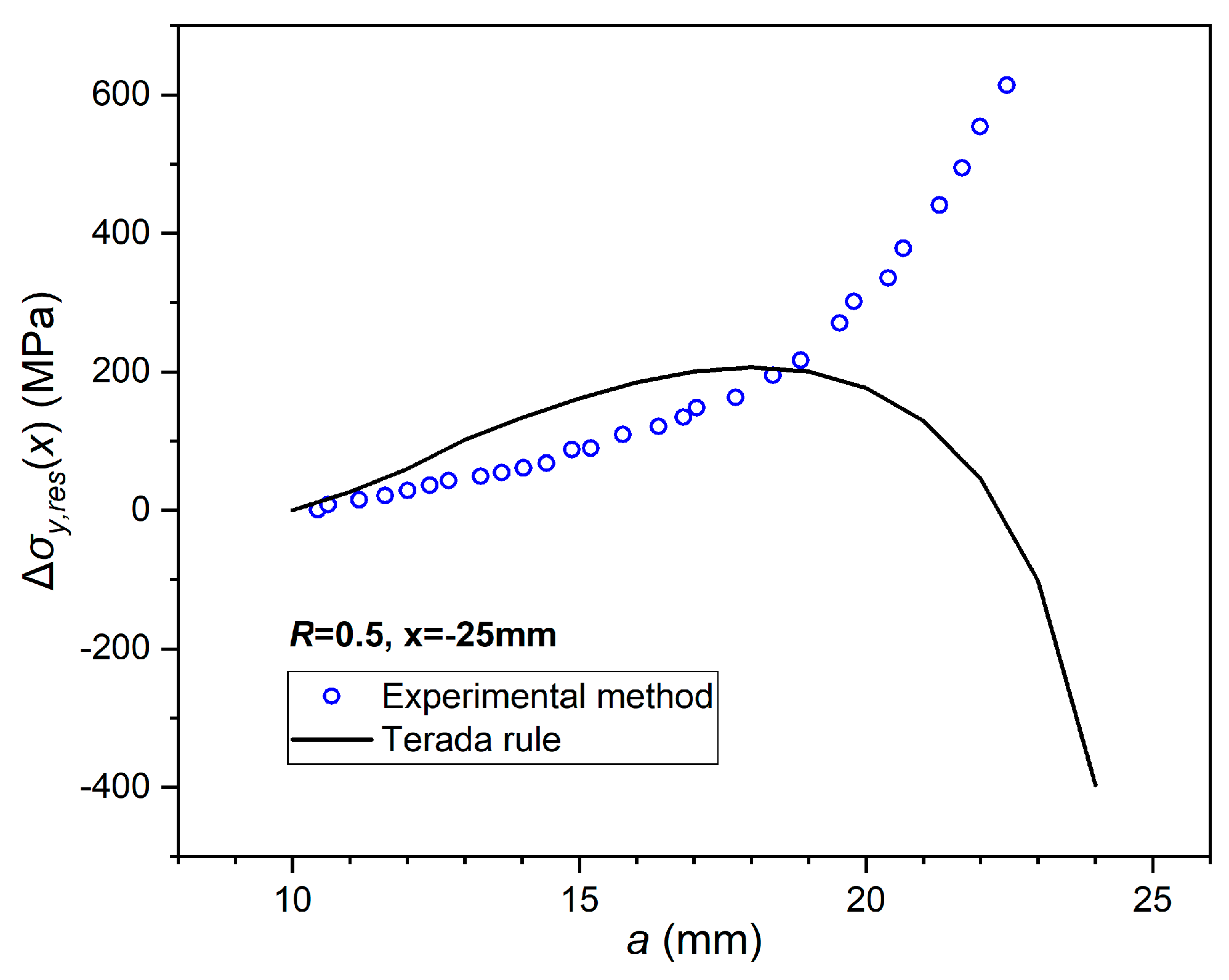
The results of the experiment method and the Terada rule are compared in
Figure 7. Predictions of the Terada rule keep the same growth rate and trend with the experiment method at the early and middle stages of crack propagation (
a=10~18mm). However, at the later stage of crack propagation (
a=18~25mm), when the crack tip becomes much closer to measuring points, the predicted result of the Terada rule changes to compressive stress while the experiment result is still in tension. The main reason for this phenomenon is that the Terada rule neglects the plastic deformation effect on residual stress near the crack tip and regards that the detachment of the crack surface quickly releases residual stress.
2.3.3. Influence of cyclic loading on residual stress distribution
To investigate the influence of cyclic loading on longitudinal residual stresses, The WRS variation without pre-cracked butt joint specimens under cyclic loading was measured, as shown in
Figure 8, where the vertical axis represents the change value of longitudinal welding residual stress re-distribution. From
Figure 7 and
Figure 8, it can be seen that throughout the cyclic loading process, the change of WRS in the butt specimen without pre-cracks is much smaller than that in the butt specimen with pre-cracks. The reason is that there are significant changes in residual stress when the sum of the applied stresses and the residual stresses locally exceeds the material’s yield strength before the cracks appear. In this study, the sum of the applied and residual stresses is less than the material yield strength. Therefore, the cyclic loadings have little influence on the WRS distribution.
3. Finite element analysis
3.1. Import of initial welding residual stress
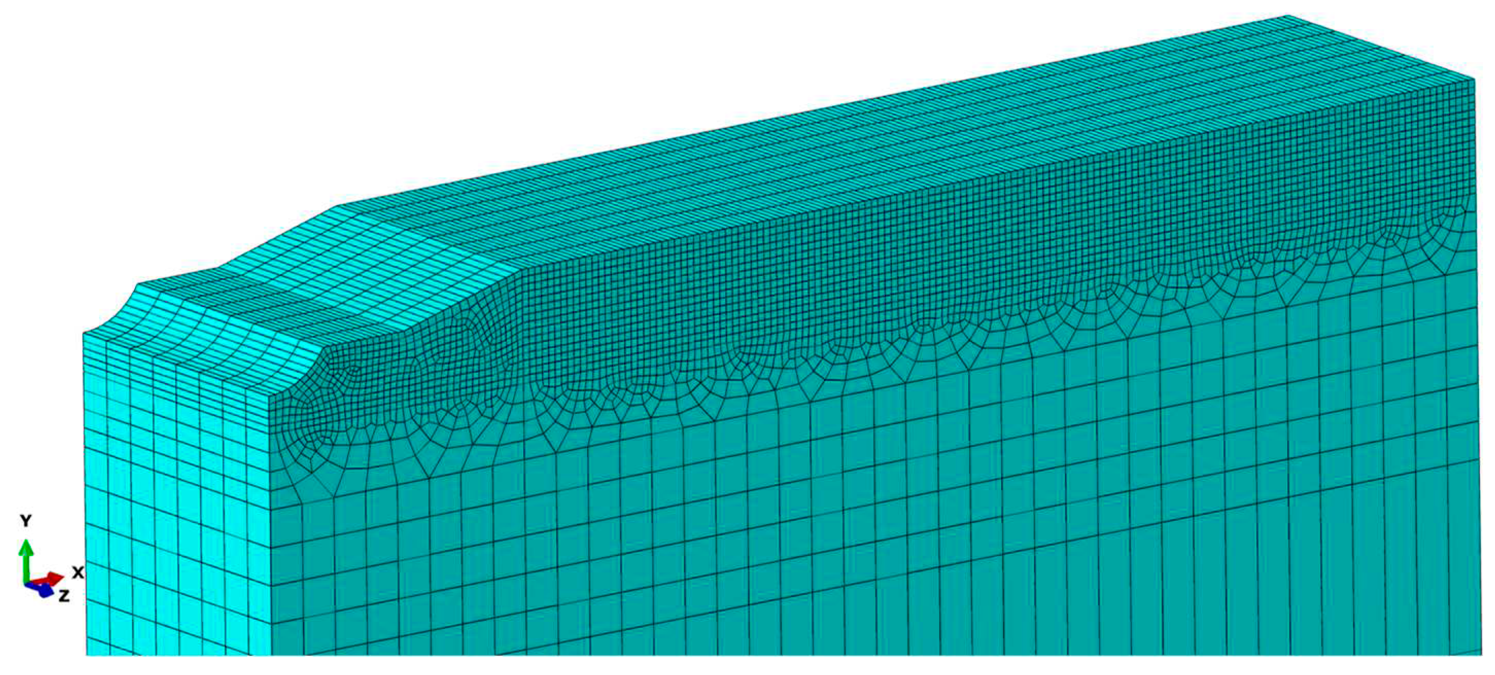
The initial longitudinal WRS measured by X-ray was imported into the FE model, as shown in
Figure 9. It is assumed that the material’s properties of the base and welding material are the same to simplify the calculation [
15]. The Import processes of initial WRS are as follows: (1) meshing the model and dividing several sets of elements by identical abscissa
x; (2) compiling keyword instructions to assign longitudinal initial WRS to the elements sets; (3) setting boundary conditions and performing self-balance calculation. The initial WRS distribution, as shown in
Figure 10, represents the residual stress distribution of the model after self-balance.
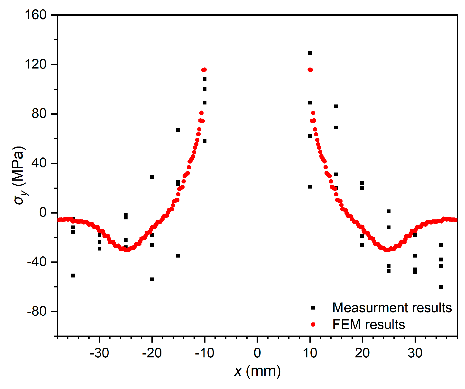
To verify whether the initial WRS distribution on the FE model is reliable, initial WRS data of the butt specimen measured by X-ray with pre-cracks were compared with the FE model’s results after self-balance. As shown in
Figure 11, the stress distribution after self-balance is close to the actual measured results in terms of magnitude and characteristics, as a result of which the initial WRS field obtained from the simulation is considered to be accurate and can be used as the initial state for subsequent re-distribution behaviour and crack propagation simulation study.
3.2. Residual stress intensity factor Kres by XFEM
According to the empirical formula of SIF in fracture mechanics [
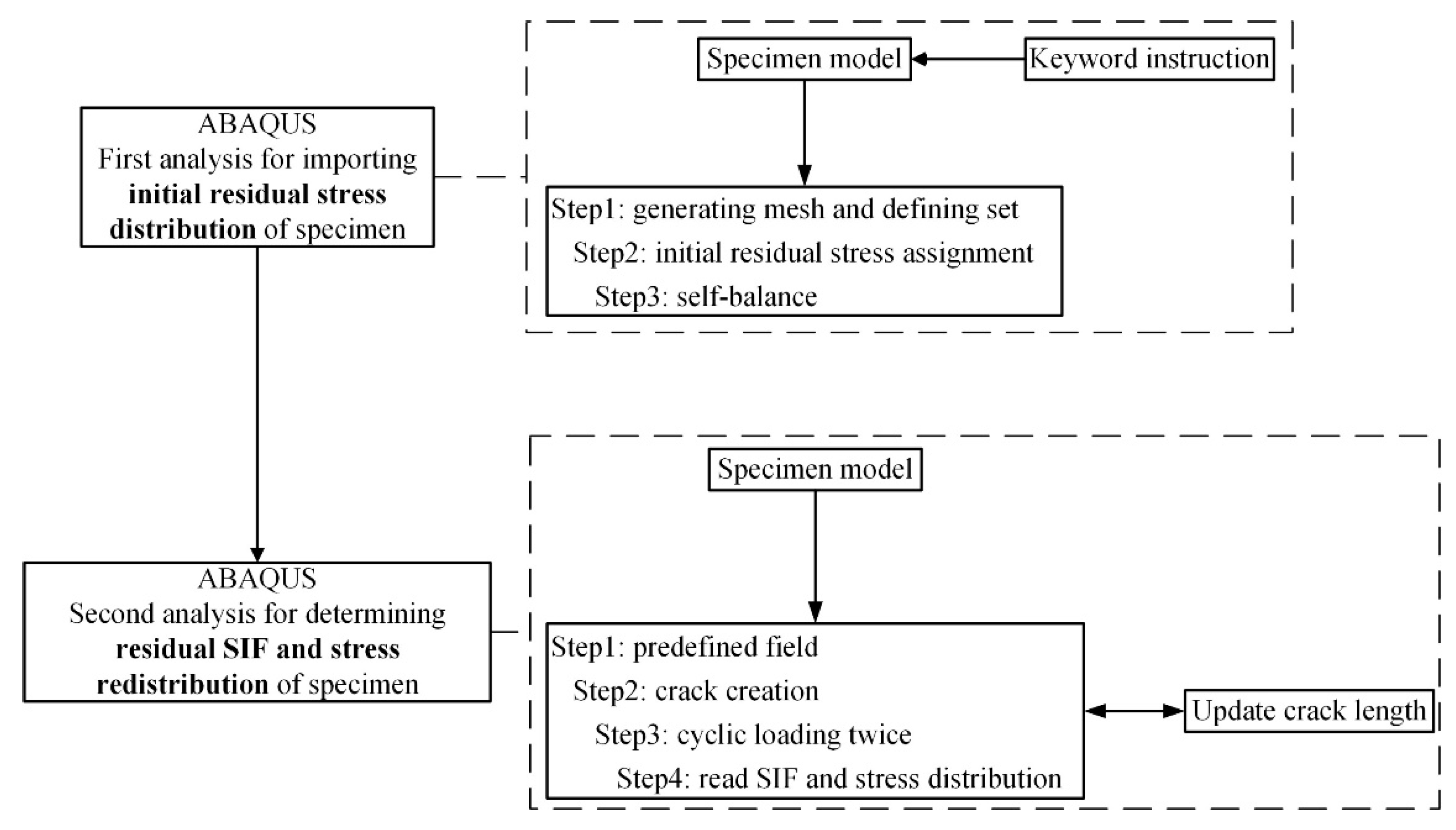
16], when the crack increment is very small, the value of SIF changes very little and can be assumed to be a constant. This study assumes that SIF in the crack tip is constant during each crack increment. The elastic-plastic simulation method of continuous crack propagation considering WRS re-distribution is based on the extended finite element method (XFEM). The procedures of the simulation are shown in
Figure 12.
The procedures of this simulation method are as follows: First, importing initial stress distribution into the FE model (in
Section 3.1) and then calculating stress-strain value for the first crack increment step under cyclic loadings. After that, the crack length will be updated, yet all elements’ numbers will be kept following the initial model (i.e., the first increment step model). A predefined field technique is deployed to read the stress-strain state of each element under the previous crack length and assign it to the current model. The above steps are repeated until they reach the maximum allowable crack length.
Kres at the crack tip of each increment will be extracted by J-integral. Ten-layer integral contours are set to calculate the
Kres at the crack tip of each increment, and all convergent contour results average the final calculation result. It should be noted that when reading the
Kres, the external load has been unloaded to 0.
3.3. Effect of cyclic loadings on the simulation results
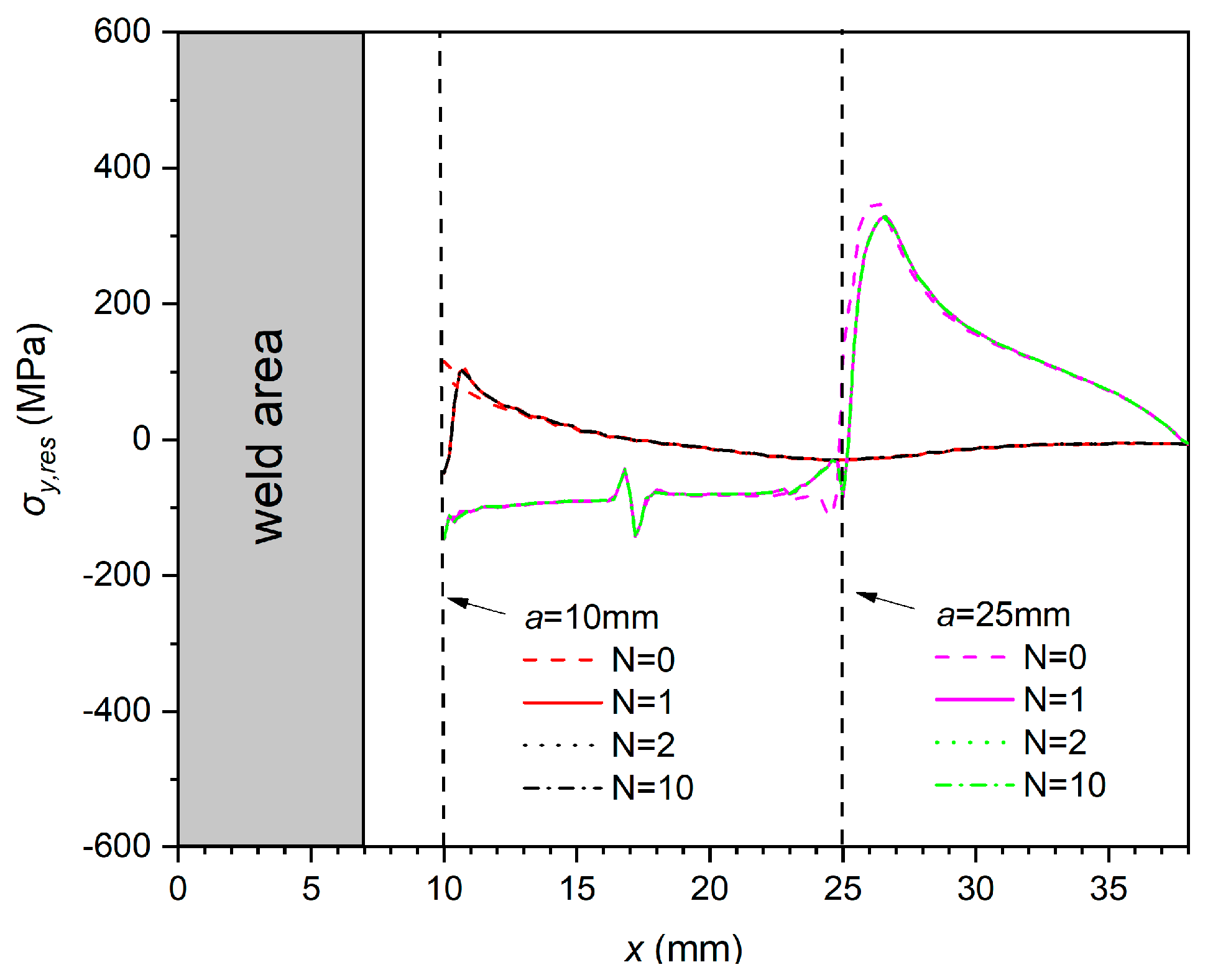
As shown in
Figure 13, longitudinal WRS distribution near the crack tip changes significantly after the first cycle of loading (N=0 vs. N=1). But the distribution hardly changes further when the number of cycles continues to increase (N=2 to N=10). This phenomenon indicates that the re-distribution behaviour of residual stresses by loading cycles mainly occurs in the first cycle. This phenomenon is because the significant changes in the longitudinal WRS distribution during the first cycle are associated with the quasi-static relaxation effects mainly caused by the applied load in the same direction as the residual stress. Therefore, in the elastic-plastic simulation of fatigue crack propagation, it is necessary to make the finite element model undergo at least one complete cyclic loading before obtaining the residual stress distribution and
Kres.
3.4. Simulation results and comparison
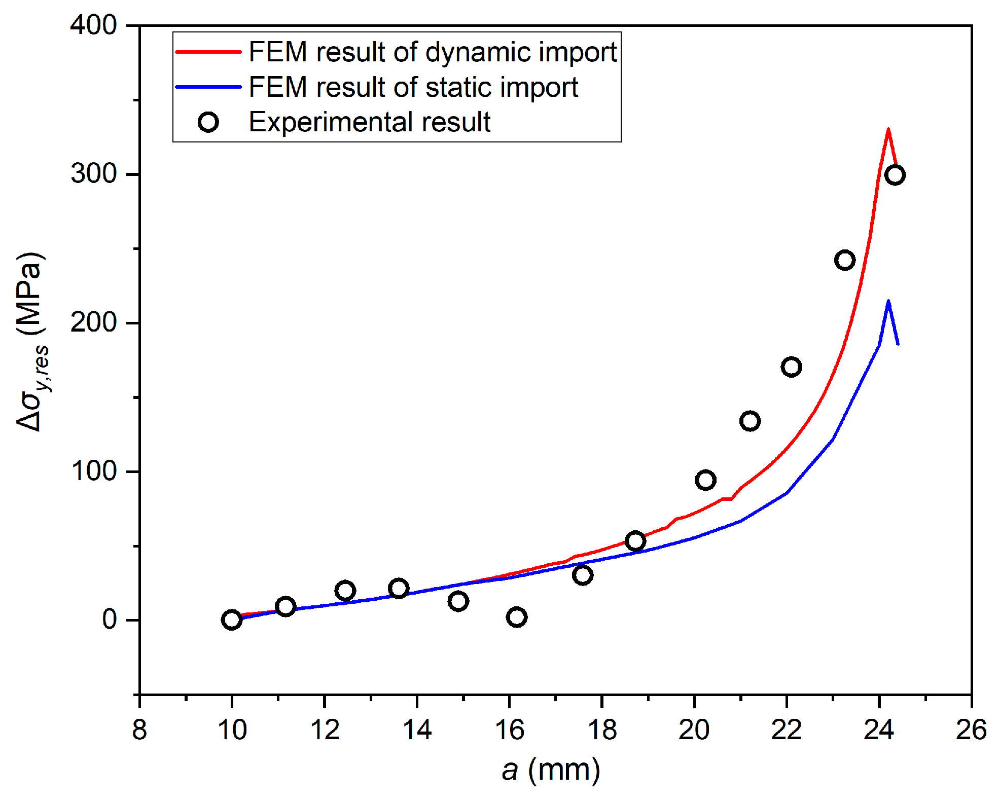
The traditional static import simulation method and the continuous dynamic one established in this study are used to calculate the longitudinal WRS re-distribution on the crack extension line with different crack lengths at R=0.1, which are compared with the experimental results at x=-25mm, as shown in
Figure 14.
It can be seen from
Figure 14 that the calculation results of two finite element methods are close to each other in the front and middle sections of the curve. The static method’s results are significantly smaller in the curve’s rear section than the dynamic and experimental data. The main reason for this phenomenon is that the static method does not consider plastic re-distribution behaviour during crack propagation. When the crack length is short, crack tip plasticity does not affect the measuring point. Therefore, the elastic component of re-distribution is dominant, and the three methods have few differences. However, the plastic component increases simultaneously when the plastic zone is gradually close to the measuring point.
Considering the plasticity, the elastic-plastic continuous dynamic simulation method is generally closer to the experimental results. This phenomenon indicates that the method established in this study can obtain a more accurate residual stress field re-distribution behaviour.
4. Residual stress intensity factor Kres
4.1. Theoretical calculation
The weight function method(WFM) based on research [
20,
21] is commonly used to quantify residual stress distribution’s effect and estimate residual stress SIF
Kres. The
Kres calculation equation for WFM is as follows:
where
h(a, x) is a weight function that depends on the crack length
a and the abscissa
x.
This study uses three kinds of σ
y(x) distribution functions. They are the Terada distribution function, the Tada & Paris distribution function as shown in the previous
Section 2.3.1., and a segmented approximation function (SAF) distribution based on measured data, which can be expressed as
Different structures correspond to different weight functions. Various weight functions,
h(
a, x), are applicable for MT specimens, and the accuracy of these weight functions is similar, as has been demonstrated by many scholars [
19,
22]. In this study, two weight functions [
23,
24], as shown in Eq. (10) and Eq. (11) are used for comparison and verification:
where
where
W=76mm denotes the width of the specimen.
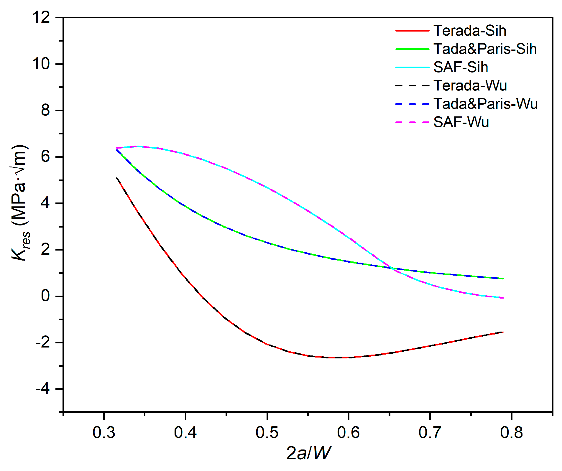
Weight functions and initial WRS distribution functions mentioned above are combined and used to calculate the
Kres vs.2a/W curve, as shown in
Figure 15. As illustrated in
Figure 15, when initial distribution functions
σy(x) are the same, calculation results of different WFM are almost identical in the effective extension range (
2a/W= 0.315-0.789) of MT specimen. Therefore, these two weight functions’ accuracy is considered consistent and will not be distinguished in the subsequent discussion. However, when the initial distribution function changes, the calculation results of
Kres significantly change as well. This phenomenon indicates that
σy(x) is the key factor in estimating
Kres when using WFM.
4.2. Results and discussion
The
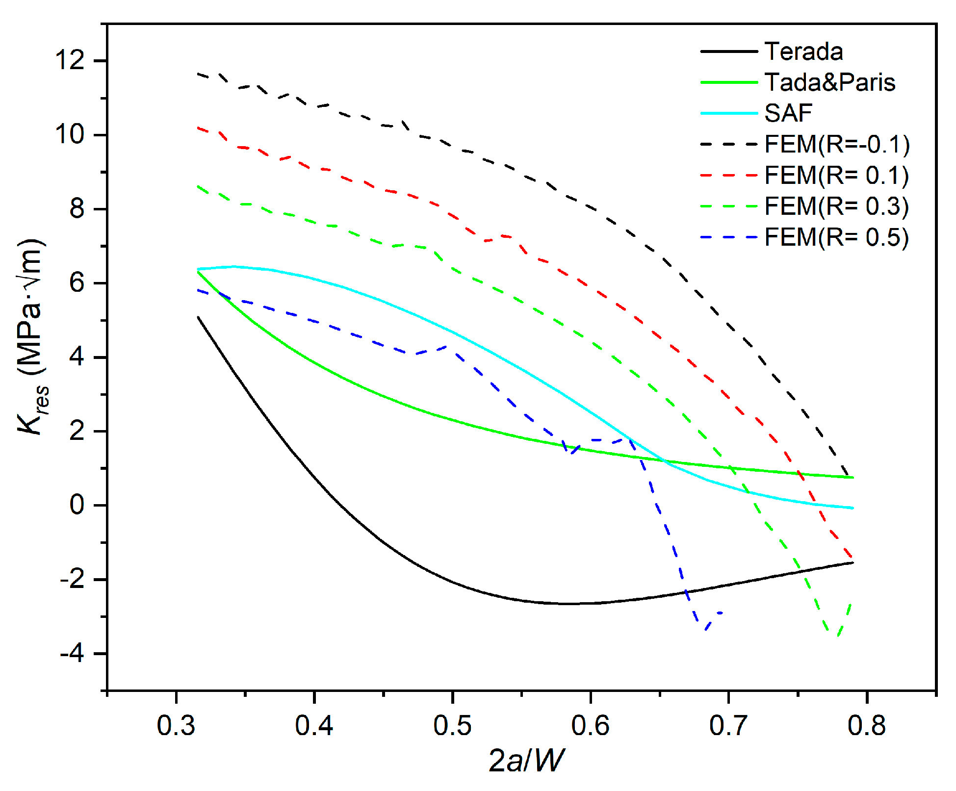
Kres-2a/W curve is calculated and summarized based on the elastic-plastic FE simulation in
Section 3.2., which is compared with the calculation results of WFM above, as shown in
Figure 16.
The magnitudes of Kres predicted by WFM and the FE method are similar, all in the range of -4~12MPa·m1/2. At the same time, WFM neglects the effect of plastic deformation on residual stress near the crack tip, resulting in a different trend.
With the crack length increase,
Kres calculated by almost all methods shows a decreasing trend, except for that using the Terada distribution. Combined with the initial WRS distribution in
Figure 5, it is speculated that the increase of
Kres may be related to the overestimation of peak compressive stress when using the Terada distribution. The
Kres curve predicted by Terada distribution turned to increase near
2a/W = 0.55, where the initial residual stress is precisely located near the right side of the compressive stress peak, increasing
Kres corresponding to the release of compressive stress during crack propagation;
The calculation results of WFM depend on the choice of the initial distribution function. Weight function adopting initial distribution SAF, which is very similar to that in the FE model, obtains the closest results to the simulation method. While there is a significant difference between the results of Terada and Tada & Paris function. This phenomenon indicates that when predicting Kres, the accuracy significantly depends on the initial distribution;
With the increase of
2a/W, there is a significant difference between WFM and simulation results. It can be seen from
Figure 15 that the trend of the
Kres-2a/W curves of the WFM tends to be stable no matter what initial distribution is used. The influence of the elastic-plastic behaviour of the material causes this phenomenon. When the local stress is close to the fracture limit, a large yield area occurs on the specimen, resulting in its re-distribution behaviour almost entirely dominated by plasticity. Crack tips and surfaces are subjected to the compression of the plastic zone after unloading, and the
K value extracted by the J-integral gradually decreases. However, WFM is based on linear elasticity assumption, considering that the residual ligament of the specimen is too short to lead to the general release of residual stress. Besides, the influence of plastic re-distribution of residual stress on crack tip is not considered in WFM. Therefore, WFM cannot predict the rapid decrease of
Kres when the specimen approaches the fracture toughness;
The Kres-2a/W curves calculated by the simulation considering the elastic-plastic response of materials show a significant stress ratio effect, which WFM cannot predict.
4.3. The stress ratio effect of Kres
As seen from
Figure 16, with the increase of stress ratio
R, the
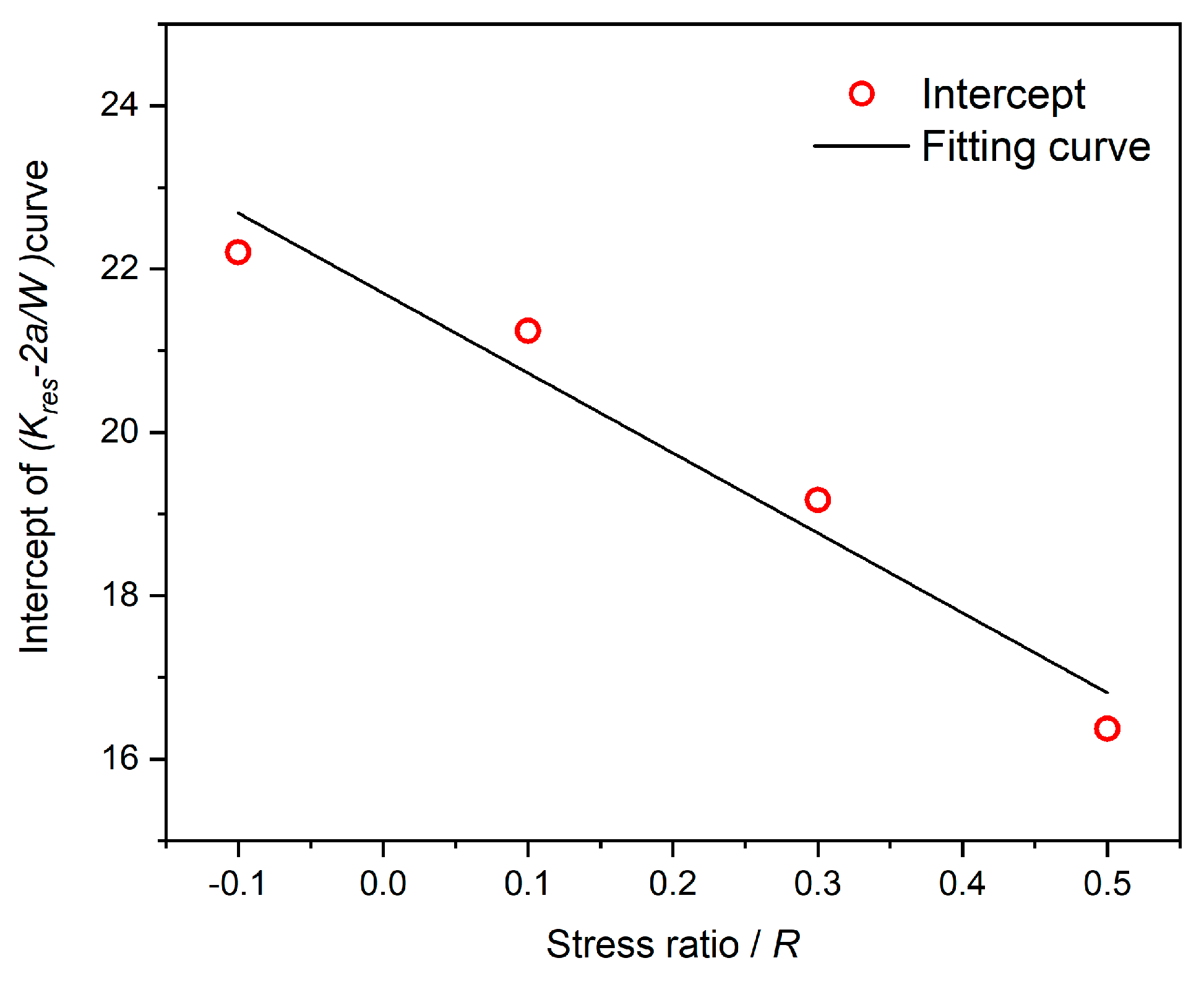
Kres-2a/W curve calculated by the simulation method shifts downward while the variation trend of the
Kres-2a/W curve at different stress ratios is almost the same. Therefore, it can be considered that the intercept of the
Kres-2a/W curve is related to the stress ratio
R.
As shown in
Figure 17, the intercept of the
Kres-2a/W curve shows a strong linear relationship with stress ratio
R. Therefore, it is assumed that the
Kres-2a/W curve is linear with the decreasing offset degree of stress ratio
R in this study. The
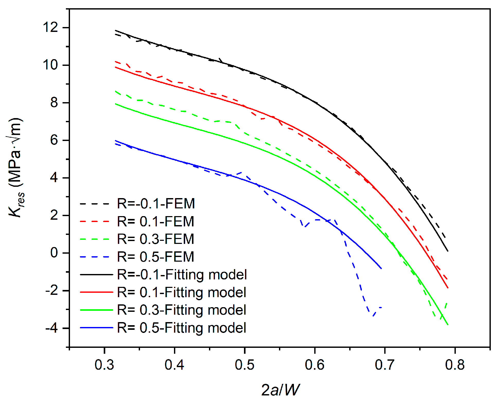
Kres-2a/W curve is fitted using a cubic polynomial based on the calculation results of the FEM. The fitting model is expressed as follows:
As shown in
Figure 18, the predicted results of the fitted model at different stress ratios are in general agreement with FEM results, with slight errors only when
2a/ W is large (corresponding to the late stage of crack propagation). The main reason for this phenomenon is that when the crack length approaches the maximum stable growth length of the specimen, the specimen will undergo a large range of plastic yield. At this time, the crack surface is subjected to compressive stresses from the plastic zone at the crack tip, resulting in a low negative value of
Kres calculated by FEM. In general, the prediction deviation of the fitted model is acceptable due to the small magnitude of
Kres. Therefore, for the MT specimens in this study, the fitted model is accurate enough to predict
Kres.
5. Conclusions
This study uses theoretical, experimental, and finite element methods to study the re-distribution behavior of welding residual stress in Ni-Cr-Mo-V steel butt-welded specimens during crack propagation. For MT butt-welded specimens, the initial residual stress was measured, and a series of crack propagation experiments were carried out. The residual stress intensity factor Kres of the specimen was calculated by the weight function method and elastic-plastic continuous crack propagation simulation procedure established in this study. According to the results of theoretical, experimental, and finite element methods, the following conclusions can be drawn:
Compared with the Terada re-distribution rule and static simulation method with initial distribution, the elastic-plastic continuous simulation method considering load timing is more consistent with the experimental measurements, which indicates that the plastic re-distribution behaviour should be considered in the simulation of fatigue crack propagation,
The accuracy of the weight function method depends on the selection of the initial distribution function. Meanwhile, the stress ratio effect of Kres cannot be predicted by the weight function method;
The Kres values calculated by elastic-plastic continuous simulation procedure indicate that Kres is affected by the crack size a/W and exhibits an obvious stress ratio effect when the applied stress amplitude is kept constant. Based on this phenomenon, the Kres calculation model related to a/W and R is established.
Author Contributions
Writing—original draft preparation, YX, JL and KY; writing—review and editing, JY and YG. All authors have read and agreed to the published version of the manuscript.
Funding
This research was funded by the National Natural Science Foundation of China (No. 52171320).
Informed Consent Statement
Informed consent was obtained from all subjects involved in the study.
Data Availability Statement
The data presented in this study are available on request from the corresponding author. No new data were created or analyzed in this study. Data sharing is not applicable to this article.
Conflicts of Interest
The authors declare no conflict of interest.
Nomenclature
| a |
current crack length |
| a0 |
initial crack length |
| E |
Young’s modulus |
| h |
specimen length |
| R |
loading/stress ratio |
| W |
specimen width |
| v |
Poisson’s ratio |
| CT |
compact tension (specimen) |
| FE(M) |
finite element (method) |
| LEFM |
linear elastic fracture mechanics |
| MT |
middle tension (specimen) |
| SIF |
stress intensity factor |
| WFM |
weight function method |
| WRS |
welding residual stress |
| XFEM |
extended finite element method |
|
C1, C2, γ1, γ2
|
the Chaboche combined hardening model constants |
| Kres |
residual stress intensity factor |
| ΔKeff |
effective stress intensity factor range |
| σ0 |
initial yield strength |
| Δσnominal
|
nominal stress range |
| σy |
initial longitudinal welding residual stress |
| Δσy
|
change value of initial longitudinal welding residual stress |
| σy,0 |
the maximum welding residual stress at the centre line of the welding |
| σy, res |
longitudinal welding residual stress re-distribution |
| Δσy, res
|
change value of longitudinal welding residual stress re-distribution |
| σys |
yield strength |
| σu |
ultimate tension strength |
| h(a, x) |
weight function |
References
- Adiban S, Ramu M. Study on the effect of weld defects on fatigue life of structures. Mater Today Proc. 2018,5(9):17114-24. [CrossRef]
- Edwards, L. Influence of residual stress re-distribution on fatigue crack growth and damage tolerant design. Mater Sci Forum. 2008, Vol.524-525:363-72. [CrossRef]
- Servetti G, Zhang X. Predicting fatigue crack growth rate in a welded butt joint: The role of effective R ratio in accounting for residual stress effect. Eng Fract Mech. 2009,76(11):1589-602. [CrossRef]
- Barsoum Z, Barsoum I. Residual stress effects on fatigue life of welded structures using LEFM. Eng Fail Anal. 2009,16(1):449-67. [CrossRef]
- Lee CS, Kim MH, Lee JM, Mahendran M. Computational study on the fatigue behaviour of welded structures. Int J Plast. 2011,20(3):423-63. [CrossRef]
- Terada H. Stress intensity factor analysis and fatigue behaviour of a crack in the residual stress field of welding. West Conshohocken,PA,USA: ASTM International, 2007.
- Xu X. Effects of Residual stress on Surface Crack Growth at Welded Joints: Dalian University of Technology, 2013.
- Liljedahl C, Zanellato O, Fitzpatrick M, Lin J, Edwards L. The effect of weld residual stresses and their re-distribution with crack growth during fatigue under constant amplitude loading. Int J Fatigue. 2010,32(4):735-43. [CrossRef]
- Liljedahl C, Brouard J, Zanellato O, Lin J, Tan M, Ganguly S, Irving PE, Fitzpatrick M, Zhang X, Edwards L. Weld residual stress effects on fatigue crack growth behaviour of aluminium alloy 2024-T351. Int J Fatigue. 2009,31(6):1081-8. [CrossRef]
- Liljedahl C, Tan M, Zanellato O, Ganguly S, Fitzpatrick M, Edwards L. Evolution of residual stresses with fatigue loading and subsequent crack growth in a welded aluminium alloy middle tension specimen. Eng Fract Mech. 2008,75(13):3881-94. [CrossRef]
- Wang L, Qian X. Welding residual stresses and their relaxation under cyclic loading in welded S550 steel plates. Int J Fatigue. 2022,162:106992. [CrossRef]
- ASTM. Standard Test Method for Measurement of Fatigue Crack Growth Rates. West Conshohocken,PA,USA: ASTM International, 2015.
- Terada H. An analysis of the stress intensity factor of a crack perpendicular to the welding bead. Eng Fract Mech. 1976,8(2):441-4. [CrossRef]
- Tada H, Paris PC. The stress intensity factor for a crack perpendicular to the welding bead. Int J Fract. 1983,21(4):279-84. [CrossRef]
- Qiang B, Li Y, Yao C, Wang X. Through-thickness welding residual stress and its effect on stress intensity factors for semi-elliptical surface cracks in a butt-welded steel plate. Eng Fract Mech. 2018,193:17-31. [CrossRef]
- Perez N. Fatigue Crack Growth. Fracture Mechanics. Cham: Springer International Publishing; 2017, pp. 327-72. [CrossRef]
- Beier HT, Schork B, Bernhard J, Tchoffo Ngoula D, Melz T, Oechsner M, Vormwald M. Simulation of fatigue crack growth in welded joints: Simulation des Ermüdungsrisswachstums in Schweißverbindungen. Materwiss Werksttech. 2015,46(2):110-22. [CrossRef]
- Ngoula DT, Beier HT, Vormwald M. Fatigue crack growth in cruciform welded joints: Influence of residual stresses and of the weld toe geometry. Int J Fatigue. 2017,101:253-62. [CrossRef]
- Wang, Q. Fatigue Crack Growth Behavior of 10Ni5CrMoV High Strength Steel Welded Joints: Harbin Institute of Technology, 2018.
- Rice JR. Some remarks on elastic crack-tip stress fields. Int J Solids Struct. 1972,8(6):751-8. [CrossRef]
- Bueckner H. Novel principle for the computation of stress intensity factors. Z Angew Math Phys. 1970,50(9).
- Bao R, Zhang X, Yahaya NA. Evaluating stress intensity factors due to weld residual stresses by the weight function and finite element methods. Eng Fract Mech. 2010,77(13):2550-66. [CrossRef]
- Sih GC, Paris P, Erdogan F. Crack-tip, stress-intensity factors for plane extension and plate bending problems. J Appl Mech. 1962. [CrossRef]
- Wu XR, Carlsson AJ. Weight Functions and Stress Intensity Factor Solutions. Oxford, UK: Pergamon Press, 1991.
Figure 1.
Geometry of the MT specimen: (a) global; (b) local detail. (Unit: mm).
Figure 1.
Geometry of the MT specimen: (a) global; (b) local detail. (Unit: mm).
Figure 2.
Measurement of initial residual stress (a) measurement device; (b)measurement paths.
Figure 2.
Measurement of initial residual stress (a) measurement device; (b)measurement paths.
Figure 3.
(a) Scheme of crack propagation experiment system (b) measuring point layout.
Figure 3.
(a) Scheme of crack propagation experiment system (b) measuring point layout.
Figure 4.
Initial WRS distribution of butt specimen without pre-cracks at different paths.
Figure 4.
Initial WRS distribution of butt specimen without pre-cracks at different paths.
Figure 5.
Initial WRS of butt specimen without pre-cracks by X-ray and distribution function.
Figure 5.
Initial WRS of butt specimen without pre-cracks by X-ray and distribution function.
Figure 6.
Initial WRS distribution of three types of MT specimens.
Figure 6.
Initial WRS distribution of three types of MT specimens.
Figure 7.
Experimental and theoretical results of residual stress re-distribution.
Figure 7.
Experimental and theoretical results of residual stress re-distribution.
Figure 8.
Variation of longitudinal residual stress with the number of cyclic loadings.
Figure 8.
Variation of longitudinal residual stress with the number of cyclic loadings.
Figure 9.
Meshing scheme of MT specimen (1/4 model).
Figure 9.
Meshing scheme of MT specimen (1/4 model).
Figure 10.
Initial WRS distribution in FE model: (a) before self-balance; (b) after self-balance.
Figure 10.
Initial WRS distribution in FE model: (a) before self-balance; (b) after self-balance.
Figure 11.
Measurement and simulation results of the initial longitudinal WRS distribution.
Figure 11.
Measurement and simulation results of the initial longitudinal WRS distribution.
Figure 12.
Steps of elastic-plastic finite element simulations.
Figure 12.
Steps of elastic-plastic finite element simulations.
Figure 13.
Influence of fatigue load cycles on residual stress re-distribution (R=0.3).
Figure 13.
Influence of fatigue load cycles on residual stress re-distribution (R=0.3).
Figure 14.
Experimental and simulation results of longitudinal WRS re-distribution (R=0.1).
Figure 14.
Experimental and simulation results of longitudinal WRS re-distribution (R=0.1).
Figure 15.
Calculation results of different weight functions.
Figure 15.
Calculation results of different weight functions.
Figure 16.
Comparison of calculation results between WFM and simulation method.
Figure 16.
Comparison of calculation results between WFM and simulation method.
Figure 17.
Intercept of Kres-2a/W curve VS stress ratio R.
Figure 17.
Intercept of Kres-2a/W curve VS stress ratio R.
Figure 18.
Comparison between the results of fitting model and FEM.
Figure 18.
Comparison between the results of fitting model and FEM.
Table 1.
Material properties and Chaboche combined hardening model parameters of Ni-Cr-Mo-V.
Table 1.
Material properties and Chaboche combined hardening model parameters of Ni-Cr-Mo-V.
|
E/GPa |
v |
σys/MPa |
σu/MPa |
σ0/MPa |
C1 |
γ1 |
C2 |
γ2 |
| 219 |
0.35 |
635 |
688 |
565 |
66500 |
1485 |
950 |
14.25 |
Table 2.
The loading condition of MT specimens.
Table 2.
The loading condition of MT specimens.
| Specimen number |
σnominal/MPa |
R |
Control group number |
|
R-0.1 |
100 |
-0.1 |
- |
|
R0.1 |
100 |
0.1 |
R0.1-B
|
|
R0.3 |
100 |
0.3 |
R0.3-B
|
|
R0.5 |
100 |
0.5 |
R0.5-B
|
|
Disclaimer/Publisher’s Note: The statements, opinions and data contained in all publications are solely those of the individual author(s) and contributor(s) and not of MDPI and/or the editor(s). MDPI and/or the editor(s) disclaim responsibility for any injury to people or property resulting from any ideas, methods, instructions or products referred to in the content. |
© 2023 by the authors. Licensee MDPI, Basel, Switzerland. This article is an open access article distributed under the terms and conditions of the Creative Commons Attribution (CC BY) license (http://creativecommons.org/licenses/by/4.0/).


