2. Materials and Methods
The successful execution of Earth observation missions necessitates a high level of precision in orienting the satellite towards the Earth's surface. Practical experience has shown that these challenges can be addressed through the utilization of active and, in some cases, combined attitude control systems, which have the capability to provide the required level of accuracy. At present, small satellites widely employ gyroscopic systems as an active attitude control system [
15]. These systems manage the spacecraft's angular position by exchanging angular momentum between inertial rotating masses and the spacecraft's body. The adjustment of the gyroscopic system's angular momentum is achieved by regulating the rotation speed of the gyroscopes. Based on their operating principles, gyroscopic systems can be categorized into relay, pulse, and linear gyroscopic systems [
15,
16,
17,
18,
19]. Well-established methods from control theory and optimal control, such as PID (Proportional-Integral-Derivative), LQR (Linear Quadratic Regulator), PD (Proportional-Derivative), P (Proportional), RLM (Robust Linear Models), and others, are employed for the analysis of gyroscopic system dynamics [
20,
21,
22]. These methods are valuable tools for studying and optimizing the performance of gyroscopic systems. There are a number of research dedicated to gyroscopic systems where they are examined from a similar perspective. In these studies, PD controllers are commonly used as the control law, based on error and rate matching, with various methods of motion specification. Quaternion representations are frequently encountered in these studies [
13,
24]. In the work [
25], several parameterizations of motion relative to the center of mass are presented, along with the corresponding control laws for each parameterization. Each set of parameters has its own advantages and disadvantages, and the choice is typically driven by the specific objectives of the mission. However, it is evident that the ultimate results achieved tend to be analogous regardless of the chosen parameterization. The presented work focuses on specifying the orientation using a matrix of direction cosines. An important aspect is the selection of the proportional and derivative (PD) controller coefficients. Ultimately, these coefficients can affect parameters such as the turnaround time, energy consumption, and more. In the current study, the criterion for selecting these parameters is the speed of transient processes. In some works dedicated to gyroscopic system algorithms, the question of parameter selection is either omitted [
26], and only a few algorithm performance examples are provided, or numerical methods are used to determine these parameters [
27].
To assess the responsiveness of attitude control for the rotation of the spacecraft relative to the position of the antenna-optical systems, dynamic Euler's equations were employed. These equations can be expressed as follows:
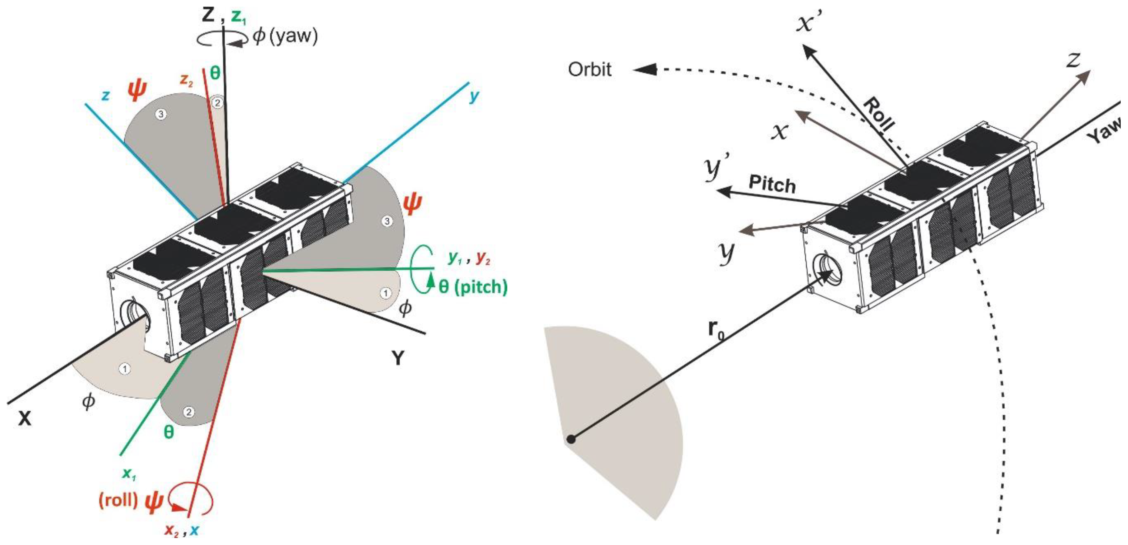
For deriving the system of equations (1), Euler angles (
Figure 1) were utilized, along with transition matrices from the spacecraft-fixed coordinate system
OXYZ to the specified system
Oxyz in the form:
The equations (1), concerning the principal moments of inertia, can be simplified through linearization and rewritten in the following form:
where
represents the mean motion, with
μ being the gravitational parameter and
representing the initial radius from the center of mass of the Earth. This parameter is crucial for characterizing the average orbital motion of the spacecraft.
At the given altitude, the total torque about roll (
Mx), pitch (
My), and yaw (
Mz) axes includes a perturbing gravitational torque [
10], which can be expressed as follows:
Taking into account the presence of gyroscopes, the change in the kinetic moment of the system can be determined as follows:
where
here
ω – the spacecraft angular velocity, w
(i) – relative angular velocity of the
i – th flywheel to the spacecraft.
Taking into account the relationships given in equation (5a), the system of equations (5) can be rewritten as follows:
here
Thus, taking into account equations (3)-(5), we obtain a system of linearized equations in the following form:
here,
Transforming equation (6) to second-order small terms and assuming the diagonal form of the gyroscopes' inertia tensor, we obtain:
where
,
,
,
– the control moments of the gyroscopes, which are aligned with the principal axes of inertia of the spacecraft coinciding with the axes of the body-fixed coordinate system.
Let's consider the case of a CubeSat 3U form-factor nanosatellite. Assuming that with a uniform distribution of the payload within the satellite's volume, we can approximate
. Then, from the motion equations (7), we obtain:
Let's assume that the control moment generated by the gyroscopes is determined according to a linear law in the form of a PD controller:
To determine the unknown feedback coefficients, let's transform the system of equations (8) into the following form:
where
,
.
To determine the feedback coefficients
,
,
,
,
that are part of the coefficient matrix
, we will derive them based on the minimization of a cost or performance functional:
Certainly, the matrix
is determined as:
where
The maximum control moment
can also be incorporated as constraints within the optimization problem, ensuring that the control inputs do not exceed safe operational limits. The matrix
can be determined by solving the Riccati equation, which is a common approach in control system design for optimal control.
where
the term
represents the maximum allowable angular deviation from the desired angular position during the orientation mode. It is essentially a tolerance or constraint on how far the spacecraft's orientation can deviate from the desired or reference orientation.
3. Results
In our case where the antenna module and camera of the CubeSat are integrated (α=0), there is no energy expenditure for CubeSat orientation. This means that when antenna modules are aligned or integrated such that they have the same orientation as the payload (in our case, camera), there is no need to expend energy to control the orientation of the CubeSat. This configuration allows for energy savings during certain operational modes when orientation control is not required.
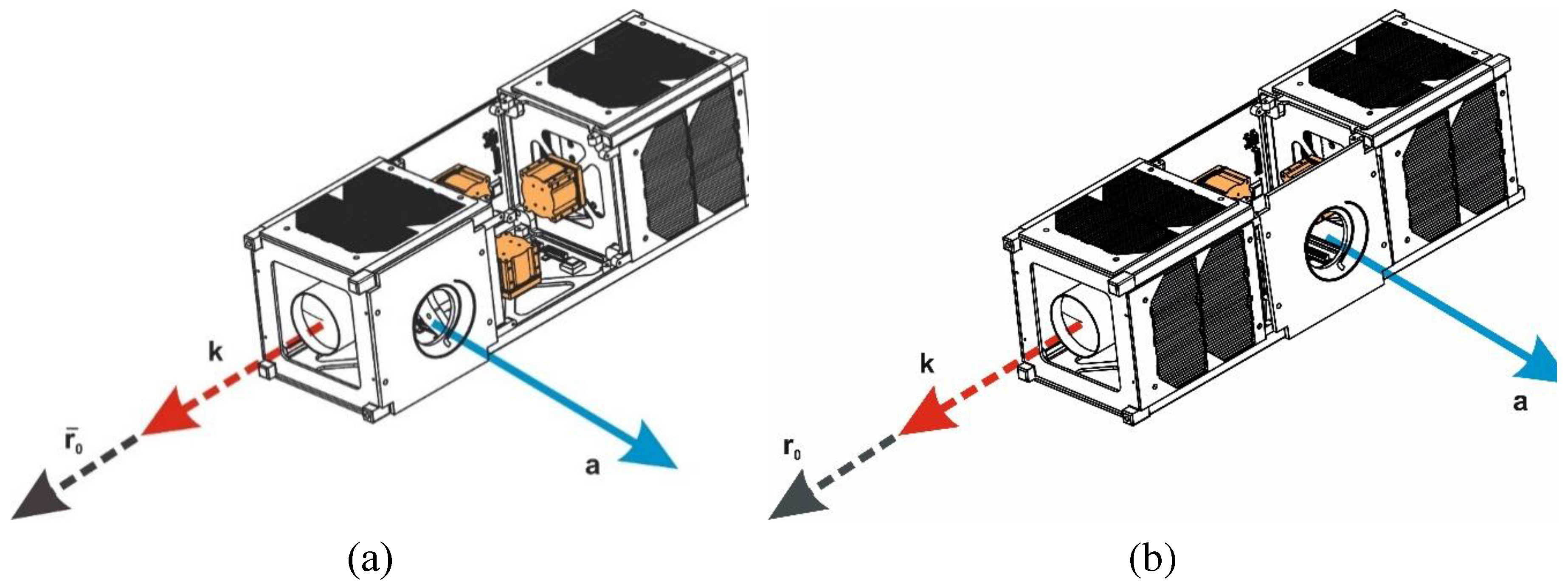
The separation of the antenna and optical systems necessitates a transition from the data acquisition mode to the data transmission mode. This transition indeed requires additional energy expenditure. When the antenna and optical systems are separate or misaligned, switching between these modes involves several energy-consuming processes, including reorienting the spacecraft, configuring the communication systems, and potentially activating or deactivating certain components. These energy costs should be considered in the overall energy budget and mission planning for the CubeSat to ensure efficient operation and successful data acquisition and transmission. To illustrate the advantages of our approach, we considered several cases of camera and antenna module placement. In the first case, the camera and antenna module are positioned at a 90° angle to each other, meaning the angle between vectors
a and
k is α = 90° (
Figure 2), where:
a is directed along the normal to the plane of the antenna module's base,
k is directed along the axis of symmetry of the camera module, α is the angle between vectors
a and
k (
Figure 2, case (a) and (b)). In this scenario, the orientation task involves aligning vector
k with vector
a.
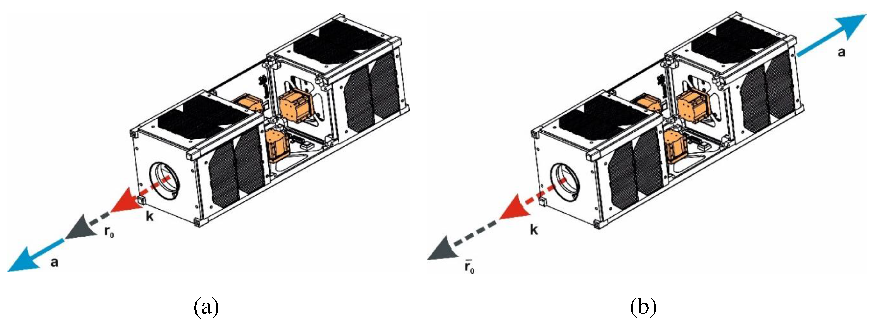
The second case, the antenna module and camera are positioned at a 180° angle to each other (
Figure 3 (b)). This configuration implies that the antenna module and camera are located directly opposite each other with a complete reversal in orientation. For clarity, in
Figure 3 (a), our proposed approach is depicted where the antenna module and camera of the CubeSat are integrated.
The moments of inertia, control coefficients and initial conditions mentioned in the context of solving equations (10) for the described cases are provided in
Table 1.
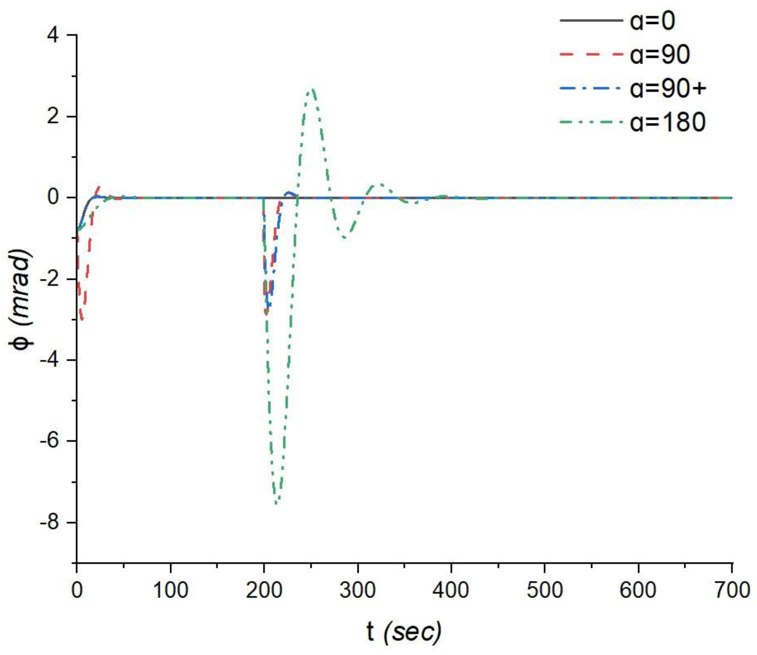
When the spacecraft rotates about its own spin axis φ, the fastest response and subsequent stabilization with respect to the target direction occur when the antenna module and optical system are positioned perpendicularly (α = 90° and α = 90°+), as shown in
Figure 4. Moreover, in the case of α = 90°, during the first spacecraft rotation, at the 5th second, the amplitude reaches -2.99 milliradians, and then at the 25th second, it decreases to 0.28 milliradians, followed by stabilization until the second rotation, where amplitude peaks of -2.85 milliradians are observed at the 201st second and 0.16 milliradians at the 223rd second of the flight, followed by further stabilization. Similarly, in the case of α = 90°+, after the commencement of orientation, an amplitude of -0.78 milliradians is reached at the 22nd second, followed by a peak of 0.03 milliradians at the 38th second of the flight, with a slight dip observed at the 2.3 milliradians, followed by further stabilization until the second rotation. During the second rotation of this scenario, amplitude peaks of -2.76 milliradians at the 205th second and 0.13 milliradians at the 226th second are observed, followed by further stabilization. In the case of α = 180°, after the commencement of orientation with an amplitude of -0.78 milliradians, the following peak at 0.3 milliradians is observed at the 48th second, followed by stabilization until the second spacecraft rotation. During the second rotation, several amplitude peaks are observed, specifically, -7.56 milliradians at the 214th second, 2.7 milliradians at the 250th second, -0.96 milliradians at the 286th second, 0.35 milliradians at the 322nd second, and -0.12 milliradians at the 358th second, followed by further stabilization. These results indicate that the relative positioning of the antenna module and optical system (α) has a significant impact not only on the time it takes to achieve orientation but also on the amplitude and phase of the spacecraft's oscillations during the orientation process. The energy consumption analysis provided according to (18) valuable insights into the impact of different α orientations on energy usage during the CubeSat's mission. For α = 90°+, the energy consumption is 1.59 mW. In contrast, for α = 180°, the energy consumption increases to 6.31 mW, which is approximately 3.97 times higher than in the perpendicular case (α = 90°+). Indeed, our analysis highlights a crucial point: in cases where the antenna module and optical system are oriented perpendicularly (α = 90°+) or in opposite directions (α = 180°), additional rotations are required when transitioning from the data acquisition mode to the data transmission mode. These extra rotations can lead to increased energy consumption compared to the scenario where α = 0°, and the camera and antenna are already aligned.
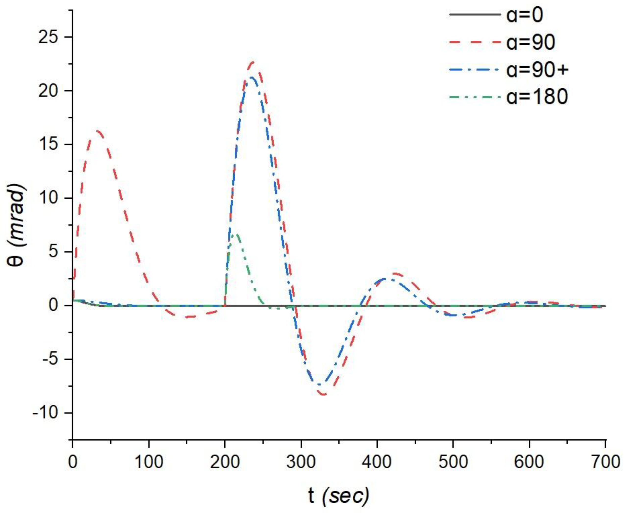
The observations regarding the orientation response of the CubeSat relative to the nutation angle θ provide valuable insights: In the case of α = 0°, after the commencement of orientation, the spacecraft stabilizes, and practically no other amplitude peaks are observed. This cannot be said for the case of α = 90°, where after the commencement of orientation with an amplitude of 0.5 milliradians, further amplitude peaks are observed at the 31st second with an amplitude of 16.3 milliradians and the 149th second with an amplitude of -1.03 milliradians in the first rotation, as well as at the 237th second with an amplitude of 22.7 milliradians, the 329th second with an amplitude of -8.25 milliradians, the 422nd second with an amplitude of 3 milliradians, and the 525th second with an amplitude of -1.09 milliradians in the second rotation, followed by stabilization. In the case of α = 90°+, after the commencement of orientation, stabilization occurs immediately until the second rotation, where peaks of 21.27 milliradians at the 235th second, -7.31 milliradians at the 324th second, 2.51 milliradians at the 412th second, and -0.87 milliradians at the 501st second are observed, followed by further stabilization. In the case of α = 180°, after the commencement of orientation, stabilization occurs until the second rotation of the spacecraft, where an amplitude peak of 6.82 milliradians is observed at the 213th second, followed by further stabilization. This means that the CubeSat can achieve the desired nutation angle relatively quickly in this configuration. However, in the perpendicular case, where the antenna module and optical system are oriented perpendicularly (α = 90°+), intense oscillations are observed over a considerably long-time interval, extending up to 650 seconds (
Figure 5). This indicates that achieving and stabilizing the desired nutation angle in this configuration takes significantly longer and involves persistent oscillations. The energy consumption and amplitude peaks for different α configurations (α = 180°, α = 90°+, and α = 90°) provide valuable insights into the trade-offs between energy efficiency and nutation control performance: In the case of α = 180°, the lowest energy consumption is observed, amounting to 11.59 mW. This configuration offers the most energy-efficient nutation control. For α = 90°+ and α = 90°, the energy consumption values are significantly higher compared to the α = 180° case.
Specifically, they are approximately 4.5 times higher, with values of 52.7 mW and 57.9 mW, respectively.
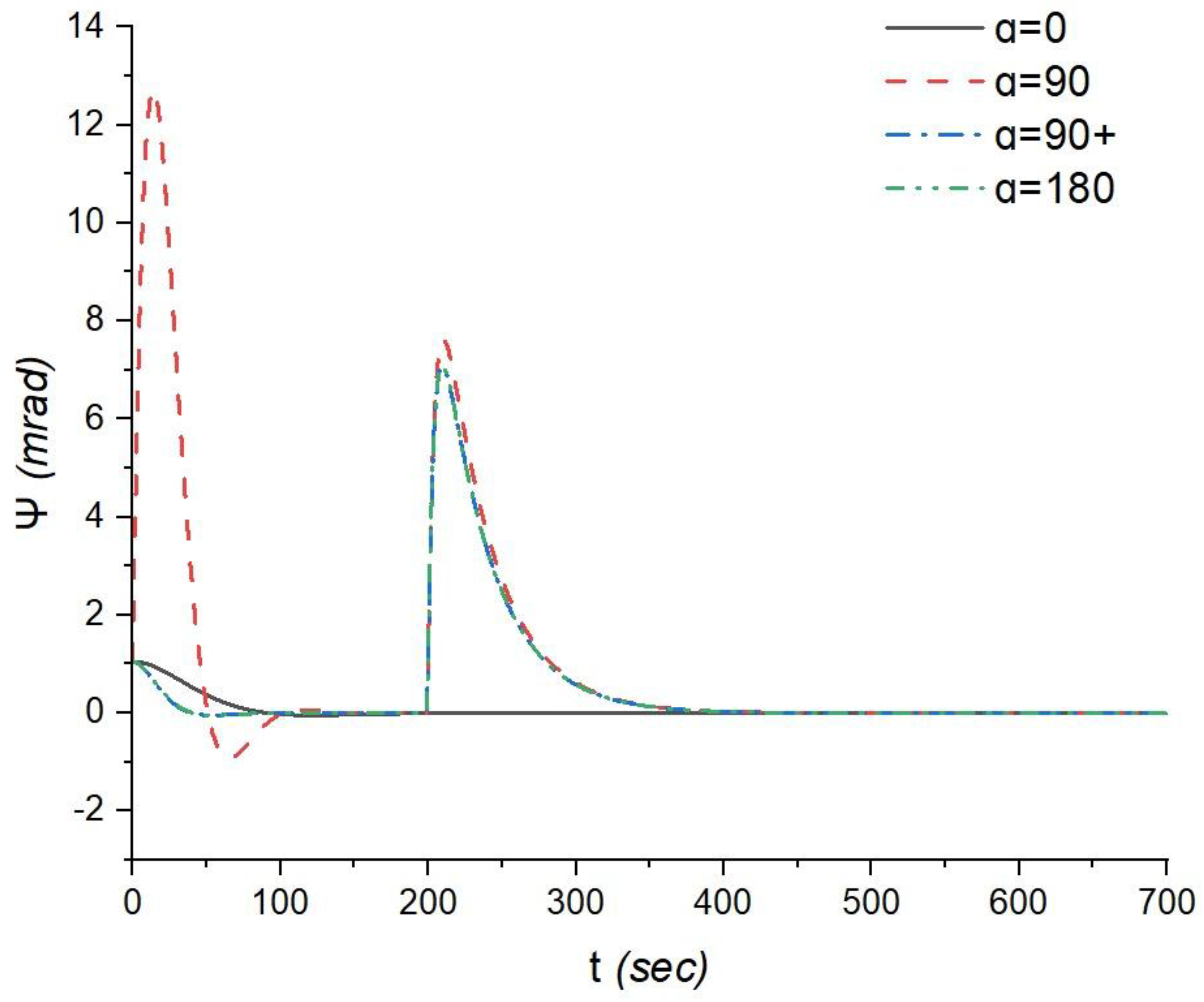
The maximum amplitude peaks for nutation control are as follows: In the case of α = 0°, after the commencement of spacecraft orientation, stabilization occurs without any other peaks observed. In the case of α = 90°, following the initiation of orientation with an amplitude of 1.05 milliradians, peaks are observed with amplitudes of 12.73 milliradians at the 14th second and -0.92 milliradians at the 65th second during the first rotation, followed by stabilization until the second rotation. In the second rotation, an amplitude peak of 7.62 milliradians is observed at the 62nd second, followed by further stabilization. In the case of α = 90°+, after the commencement of orientation, stabilization occurs until the second rotation, where an amplitude peak of 7.8 milliradians is observed at the 209th second, followed by further stabilization. In the case of α = 180°, a peak is also observed in the second rotation at 7.08 milliradians at the 209th second.
The analysis of the response of the CubeSat's control system during precession (ψ) reveals interesting insights: The relative orientation of the antenna module and optical system (α) doesn't significantly impact the time and amplitude characteristics of the precession control. Time of Precession: In both cases, α = 90°+ and α = 180°, the maximum amplitude peak for precession control is reached at 11 seconds, with an amplitude of approximately 7.03 milliradians. Damping of Oscillations: After reaching the maximum amplitude peak, the oscillations dampen relatively quickly, and orientation towards ψ asymptotically approaches zero. Energy Consumption: In both configurations (α = 90°+ and α = 180°), the energy consumption for precession control is 36.9 mW. Antenna Module Position: When the antenna module is placed above the flywheel block, there is a slight increase in amplitude, with a peak amplitude of 7.61 milliradians, still occurring at 11 seconds.
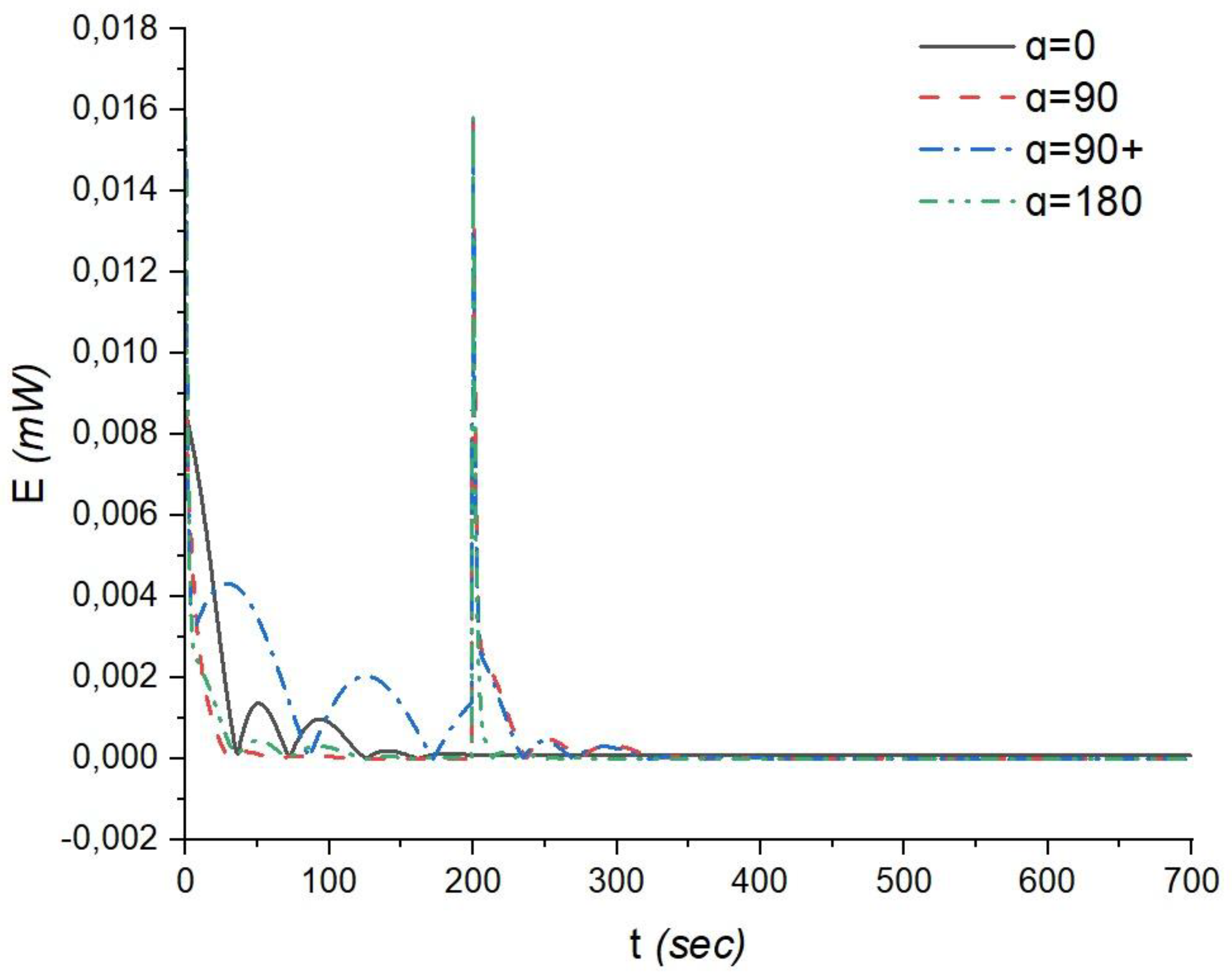
The analysis of energy consumption for orientation control in different α configurations (α = 90°+, α = 90°, and α = 180°) yields important conclusions (
Figure 7):
When α = 0°, the initial power consumption starts at 85 mW, drops to near-minimal levels by the 36th second of the flight, and increases to 13 mW and 10 mW at the 51st and 93rd seconds, respectively, with a near-minimal value at the 73rd second. Subsequently, closer to the 140th second, the power consumption rises to 2 mW, followed by stabilization at near-minimal levels.
In the case of α = 90°+, the power consumption starts at 158 mW, sharply decreases to 32 mW by the 6th second, increases to 43 mW by the 29th second, drops to near-minimal levels closer to the 86th second, and rises to 158 mW at the 200th second of the flight, followed by stabilization at near-minimal levels. The total energy required for rotation and maintaining the desired orientation over the entire duration of the mission when flying over the ground station is 100.73 mW.
For α = 90°, the power consumption starts at 85 mW, decreases, and stabilizes at near-minimal levels by the 50th second of the flight. The energy consumption is slightly higher at 111.99 mW.
For the α = 180° configuration, the power consumption, starting at 158 mW, drops to near-minimal levels by the 45th second, with slight increases to around 4 mW by the 50th and 92nd seconds, reaching near-minimal levels between them at the 71st second. The power consumption then stabilizes at a near-minimal level. In this case, the energy consumption of the flywheels is significantly lower, totaling 44.33 mW. This represents a 2.27-fold reduction in energy consumption compared to α = 90°+.
4. Conclusions
This work aimed to investigate the advantages of aligning the camera and antenna module on the CubeSat. The results show that this configuration provides the fastest response time and orientation of the optical system with minimal amplitudes, which also leads to the lowest energy consumption.
Key findings and conclusions from the study include:
Fastest Response in Roll (φ): The quickest response and subsequent stabilization relative to the target direction are achieved in perpendicular orientations (α = 90° and α = 90°+), with orientation occurring in 35 seconds.
Fastest Response in Nutation (θ): The fastest orientation relative to the target direction is observed at α = 180°, with orientation occurring in 85 seconds.
Precession (ψ): The relative angular positioning of the antenna and optical systems does not significantly affect orientation time and oscillation amplitudes. Orientation occurs in 11 seconds.
Energy Consumption: The total energy consumption for rotation and maintaining orientation over the mission duration was evaluated for different α configurations. The results indicate that the α = 180° configuration has significantly lower energy consumption (44.33 mW) compared to α = 90°+ (100.73 mW) and α = 90° (111.99 mW). This represents a 2.27-fold reduction in energy consumption compared to α = 90°+.
Overall, the study suggests that aligning the camera and antenna module in a co-axial configuration (α = 180°) offers several advantages, including faster response times, minimal oscillation amplitudes, and reduced energy consumption, making it a favorable choice for CubeSat orientation control. The findings contribute valuable insights for mission planning and design considerations.
