1. Introduction
The battery field is highly competitive nowadays, within large interests in various applications [
1,
2,
3,
4,
5,
6,
7]. Lead-acid batteries (LABs) continues to control the battery market, compromising among power, lifetime, manufacturing costs and recycling. They dominated the market share in 2019, by an estimated 32.29% of the total battery market [
8], with further prediction growth of 5.2% until 2030 [
9]. The reasons for which LABs are still competitive are mainly due to some particular features, as they exhibit high recycling rates [
10], low manuafacturing costs [
11], maintenance-free operations [
12], and safe working conditions at extreme temperatures [
13]. All these advantages continues to propel them in the top preferences of the automobile industry [
14,
15] and in off-grid storage systems [
16].
Despite of the persistent LABs improvements in terms of advanced materials and/or technological processes, there are some drawbacks that concern the batteries lifespan prediction, as a major preocupation in the field, with direct impact on the total costs of the energy systems and on the progress of LABs development. Therefore, a determination of the expected battery lifetime performance is highly needed. Several methods can be found in literature to predict battery lifetime [
17,
18,
19]. Among these, we mention the ampere-hour counting [
20], voltage method [
21], artificial neural network, currently used to predict State of Health (SoH) in electric vehicles [
22,
23], the genetic algorithm applied to the charging and discharging equations in order to estimate the value of the time constant [
24], the computing of Weibull distribution [
25],
etc. However, all these techniques are having complicated algorithms and are dificult to implement. Another common approach is aging the battery until failure, in which the battery lifespan is Depth of Discharge (DoD) dependent [
26]. The aging mechanism at different DoD can also be found in literature. For example, Kazelle
et al. [
27], have investigated the influence of cell impedance parameters on ageing the battery at 100% DoD, while the group of Morari [
28] employed a DoD of 25% in the controlled ageing mechanism. We found studies in which an optimized DoD is recommended by the battery manufacturers to be at 50% DoD [
29,
30].
Beside the above-described approaches, Electrochemical Impedance Spectroscopy (EIS) is one of the most used qualitative techniques for the examination of general states of the battery (SoC -state of charge and SoH state-of-health) [
31,
32,
33,
34,
35]. It is a highly sensitive approach employed for characterization of chemical systems (state-of-charge, fluctuations of internal resistance, interfacial processes, residual capacity,
etc) in a non-destructive manner. The battery yield is examined in the light of Nyquist diagrams together with their fitted Randles equivalent circuit [
36,
37], registering the modifications that appear on the charging/discharging processes. EIS basically follows the electrons motion dependence in the metallic components, combined with the progress of ionic migrations, electrostatic charging of double layers, and of charge transfer processes at electrode surface.
Based on this methodology, we propose in this investigation a reliable EIS analysis, able to provide accurate predictions of the LABs lifetime performance. We used 9 industrially formed prototype LAB batteries, divided on three packages, within distinct type/technology features. They were delivered by the ROMBAT enterprise, the leader of automotive batteries in our country, that also equip several car models as Dacia, Renault, Nissan and Ford vehicles across all Europe [
38].
Two particular 100% SoC stages were employed for this study: 1) immediately after fabrication; and 2) after a controlled aging procedure to 50% DoD at ROMBAT factory, following their industrial standards. The DoD emphasize here the capacity that is discharged from a full charged one, divided to its nominal capacity, or in a simple way, a percentage of the battery which have been discharged relative to the overall capacity. In the particular case of LABs, there is a link between the DoD and the battery cycle life, namely the number of charge/discharge cycles that a battery can sustain in its life, depending on how much of the battery’s capacity is usually used. We choose to cycle them in the 100% to 50% range, being known as an interval that prolong the LABs lifetime. It has been demonstrated that going below 50% discharging, the batteries will shorten their lifetime [
39].
The key elements of our investigation are focused on three fast techniques: 1) the fluctuations of (Q-Q
0) total charge exchanged at the first stage of investigation; 2) the time-dependent decomposition of the constant phase element (CPE) decomposition in the Randles equivalent circuits; 3) the resonance frequency single parameter analysis. In which concern the last two approaches, we already demonstrated previously [
40,
41,
42,
43], the viability of both methods, in which we have successfully put together the controlled aging of LABs with the PEIS measurements. By collecting the data of 6 PEIS measurements recorded when batteries are fully charged, and respectively at 50% DoD, we employed here the CPE element analysis, in order to characterize the capacitance dispersion and their variations on the CPE carriage. We follow the trends on the CPE linear decay in the equivalent circuit in both SoC phases. Beside the prediction of the LABs lifespan, we also highlight here the potential applications of these methods, as direct indicators for validation of technological innovations in automotive industry. Resonance frequency analysis has been firstly implemented in [
41], offering a fast performance prediction in lead-acid battery characterisation in terms of connection between SoH and the electric response. It was also considered a predictable factor for positive grids with hexagonal and leaf designs in novel LAB protoypes [
43]. To further expand the applicability of the resonance frequency for battery aging prediction, this method is applied in this study to LABs aged at 50% DoD.
2. Materials and methods
2.1. Lead-acid batteries type/technology
We used 9 industrially prototype LABs in our investigation, fabricated by ROMBAT factory, the dominant manufacturer of automotive batteries in our country. ROMBAT's data protection and manufacturing secrets, prevent us from providing more details about battery manufacturing parameters or other additional data. Nevertheless, in
Table 1 of the Results section, are described some general information about the type, capacity, and technology on each battery package.
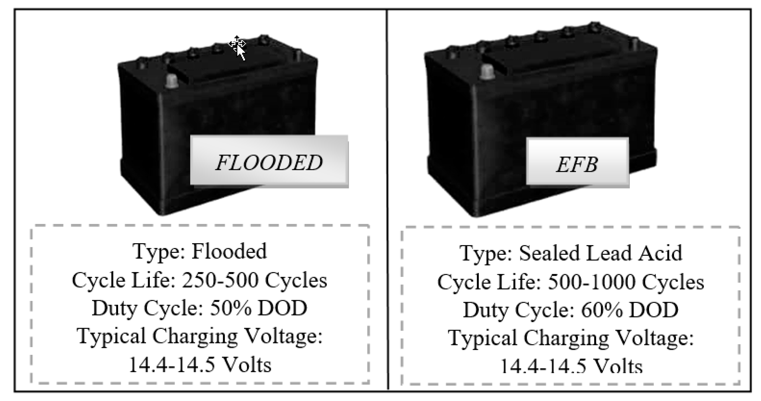
The first three types of lead-acid batteries (L2 FLO 52 Ah) were formed in a traditional flooded technological approach, in which the electrodes/plates were immersed in electrolyte. The most familiar example of a flooded lead-acid cell is a 12V automobile battery, but has the disadvantage of some maintenance during its lifetime, meaning that additional distilled water must be added from time to time in order to bring the electrolyte at the optimum level [
44].
The other 6 prototype batteries, three of type L2 EFB 60 Ah, and three of L3 EFB 70 Ah respectively, were formed through an enhanced version of standard wet-flooded technology, namely EFB, in which additional carbon additives were added during the manufacturing processes. The aim was to improve the charge acceptance and the cyclic durability when operating in current Start-Stop automobiles that usually highlight a reduced state of charge function mode. A recombinant lid technology combined with a high pack pressure was applied in order to possible improve the battery lifespan. If in the first type technology, the electrolyte solution goes in between each cell plate, for the second technology, thicker plates are used in comparison with conventional starting battery. A schematic illustration of both types, with some specific parameters is shown in
Figure 1, below.
We should mention that the scope of this work is directed exclusively to the development of accurate methods for the prediction of the LABs lifetime performance, and not on the batteries manufacturing processes. We are fully aware that the finite batteries performance is coming from the irreversible changes that occurs in the physical and/or chemical structure of its components, and a quantitative health assessment of the batteries requires data about the nature and the extent of those variations. We also know that the chemistry of the materials from which the LABs are fabricated, plays a major role in their efficiency and/or capacity, but is out of our scope here.
2.2. Experimental set-up
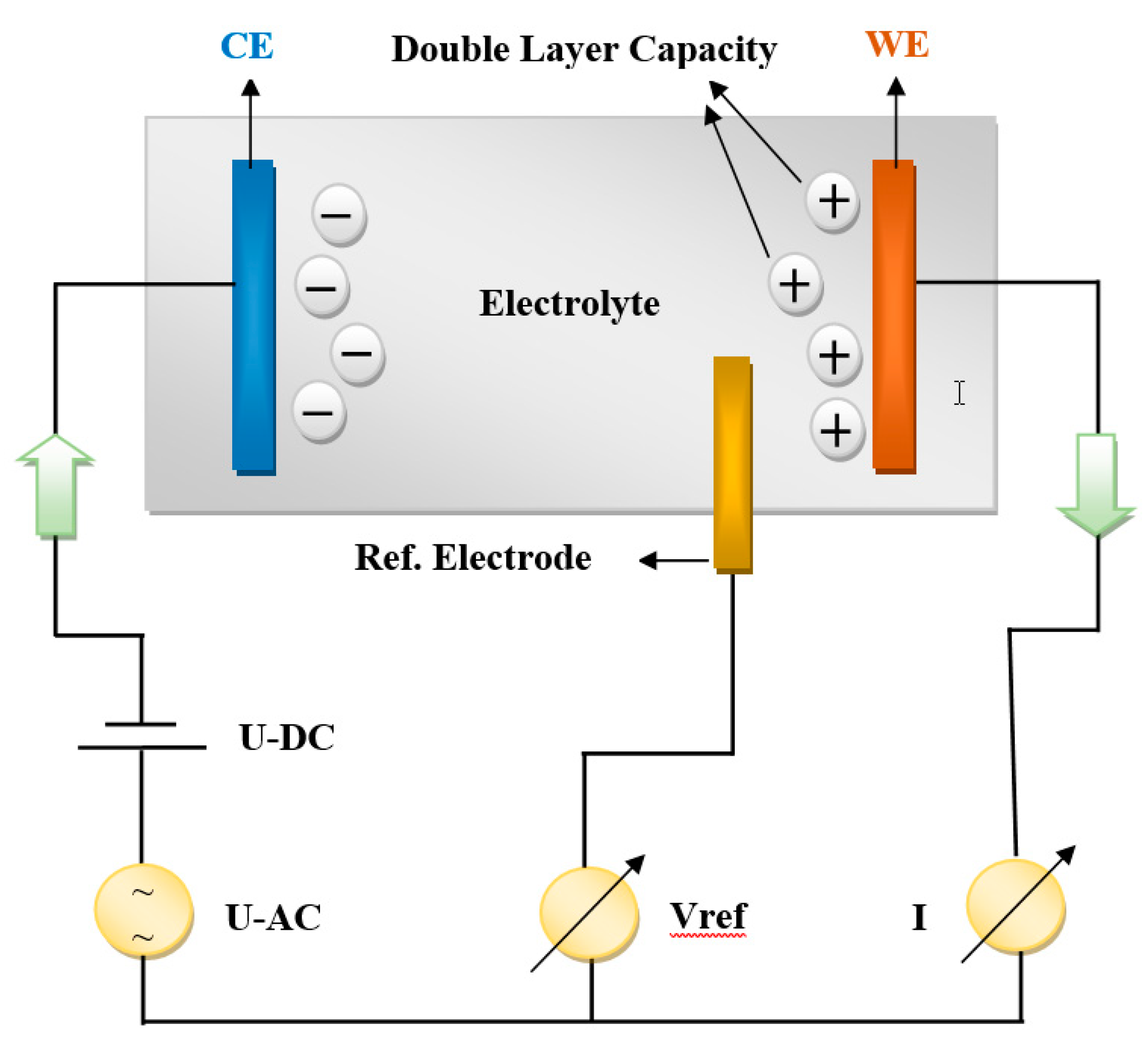
A multi-channel VSP equipment belonging to the Bio-Logic company (4 working channels in potentiostatic mode) connected to two amplifiers (boosters), of 5 A and 10 A respectively, was used for PEIS measurements, while the results were interpreted in the framework of Ec-Lab software program. Simultaneous measurements of current and working electrode potential were acquired continuously using two 16-bit Analog-to-Digital converters. A three-electrode connection with a reference electrode has been employed, allowing us to record/control simultaneously the positive and the negative part of the battery. In this configuration, was added a third voltage reference electrode to the two parallel plate electrode, CE (Counter Electrode) and WE (Working Electrode), measuring the voltage difference of the polarization double layer capacity to the WE. A schematic configuration within their internal processes is shown in
Figure 2, below.
2.3. Battery characterization procedure
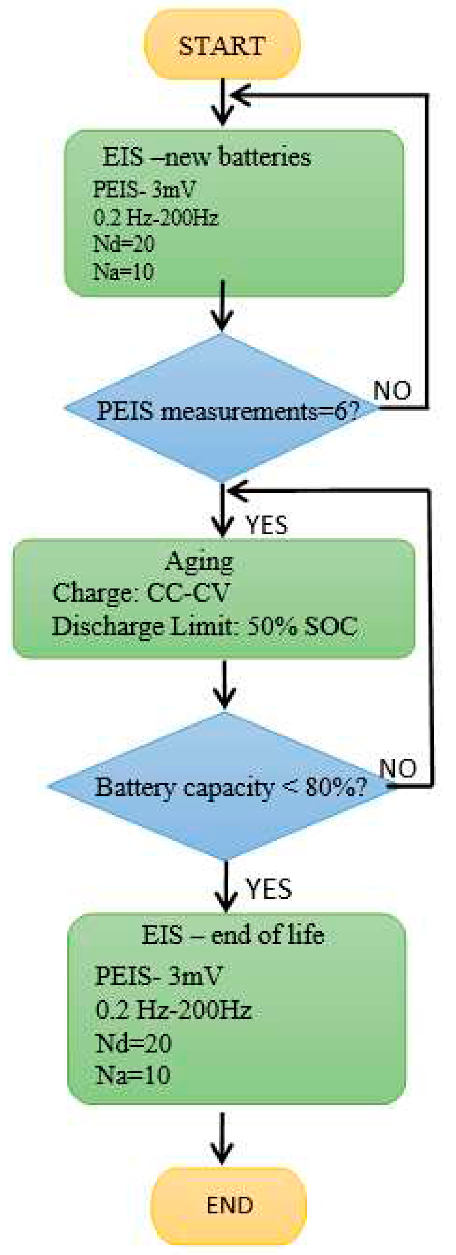
Six PEIS (Potentio Electrochemical Impedance Spectroscopy) battery measurements were performed for each battery type/technology. The experiments were carried out in two stages: the first measurements were taken immediately after manufacture when batteries were fully charged, while in the second case, the batteries were aged at ROMBAT (to 50% DoD industry standards), and then sent back to our laboratory for analysis. PEIS tests preparation at 100% SoC included 24 hours charge at 16V with 17.5A current limitations. In
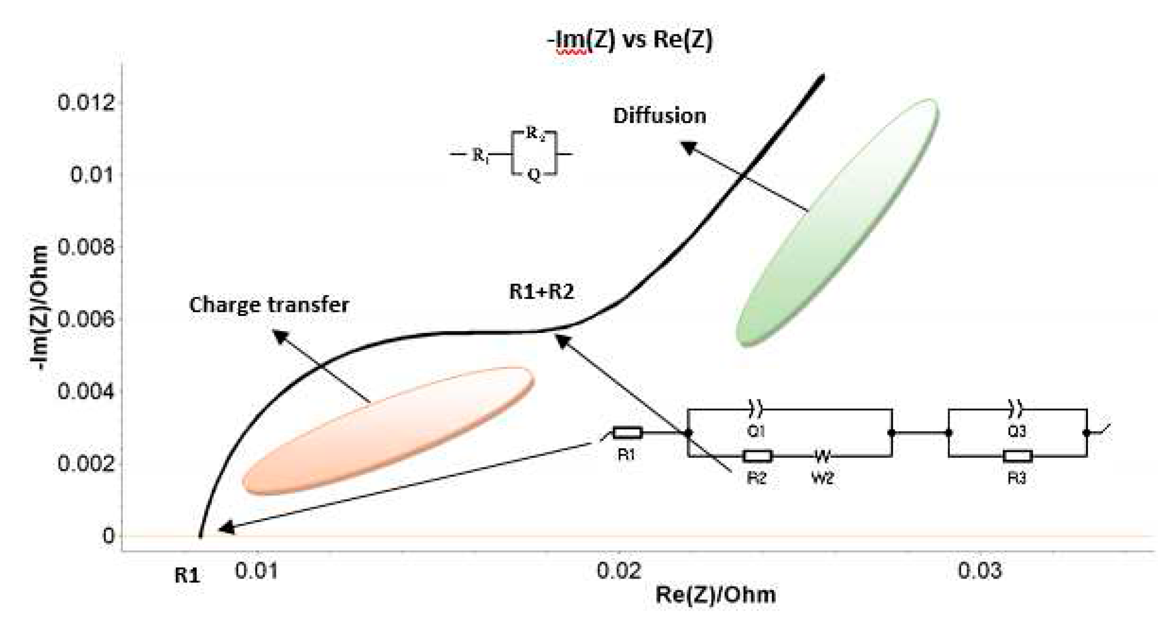
Figure 3, we summarized the working parameters in the PEIS analysis procedure. The results were interpreted in the light of Nyquist diagram, within the corresponding Randles equivalent circuit, schematically, shown in
Figure 4.
By looking on the Nyquist plot example in
Figure 4, we expect a semicircle with the center on the X real axis, while we obtained an arc of a circle but within the center placed below the axis. As such, we have associated this behavior with the capacitor imperfections, expressed by the Constant Phase Element (CPE). This element is able to describe the impedance data with non-ideal frequency dependent properties, by using the following equation:
Additonally, we monitored the error coefficient for each value of impedance calculated in Ec-Lab as:
where 𝑍𝑚𝑒𝑎𝑠(𝑖)- are the values of measured impedance and 𝑍𝑠𝑖𝑚𝑢𝑙(𝑓𝑖, 𝑝𝑎𝑟𝑎𝑚)-are the values of the measured impedance with the fitted parameters.
For all the fitted circuits employed in this investigation we got the smallest errors, with typical values for χ between 1 and 3 percent.
The main parameters of the Randles circuit used to fit the PEIS data in our experiments (see
Figure 4) are: R
1 -resistance of the electrolyte conductivity; R
2 – resistance at charge transfer; Q
1/𝑎
1, Q
3/𝑎
3 – CPE - Constant Phase elements – that describe the double layer capacity near to the two electrodes; W
2 – The Warburg element- responsible with the difussion proccesses induced at interfaces (by the production and/or consumption of elements); R3 – leak resistance.
3. Results and discussions
We summarized in
Table 1 the results of maximum number of discharging cycles (in blue) and the minimum number of discharging cycles (in red) for each batteries type.
As can be seen, for the first type/technology of B1-B3/ L2 FLO 52 Ah, the best performance achievement was obtained by the B2 battery prototype, within the largest cycle life when aged at 50% DoD. On the opposite, the B3 accumulator highlight the shortest cycle life and a minimum number of 46 discharging cycles. A middle performance was obtained by the B1 type, with 50 discharging cycles. In the case of the second batteries type of B4-B6/L2 EFB 60 Ah, the best performance is clearly detached by the B6 prototype, within a 228-maximum number of discharging cycles, while the B4 and B5 types, emphasize a much lower battery performance. However, B5 accumulator demonstrate a longer cycle life than B4, with 67 discharging cycles, compared to 56 discharging cycles. In the last package, of B7-B9/ L3 EFB 70 Ah, the B9 accumulator emphasize an even better performance than B6, within 256 -maximum number of discharging cycles. The other two types of B7 and B8 accumulators, describe a much lower performance, with just 23 discharging cycles. As can be observed, the B2, and in particular B6 and B9 batteries type/technology, have emphasized a significant increment in terms of lifetime performance by comparison with other batteries in each group. This means that depending on the type and technology used for batteries fabrication, these prototypes should be taken into account for further developments as new products innovation for automotive industry.
However, a qualitative evaluation of the LABs is needed for the determination of parameters that are influencing the most the homogeneity between electrodes, and ultimately to find an accurate fitting approach capable to predict the lead-acid cells aging process and/or their degradation speed.
3.1. Q-Q0 total charge analysis
The level of charge after each PEIS measurement has been recorded by VSL potentiostat, in terms of (Q-Q
0). This represents the total charge exchanged from the beginning of the experiment, and can be seen as the ratio between energy stored (sum of energies in capacitors and/or lossless inductors) to the energy dissipated per cycle (sum of energies dissipated/per cycle in resistors), or as a product of the electric current flowing throughout the battery (in or out) and the time duration. Starting from the fact that the magnitude of the net charge on the plate will grow with time, we have:
in which τ represent the time constant of the circuit
For Q determination, which represents the amount of charge transferred /time, the following equation is employed:
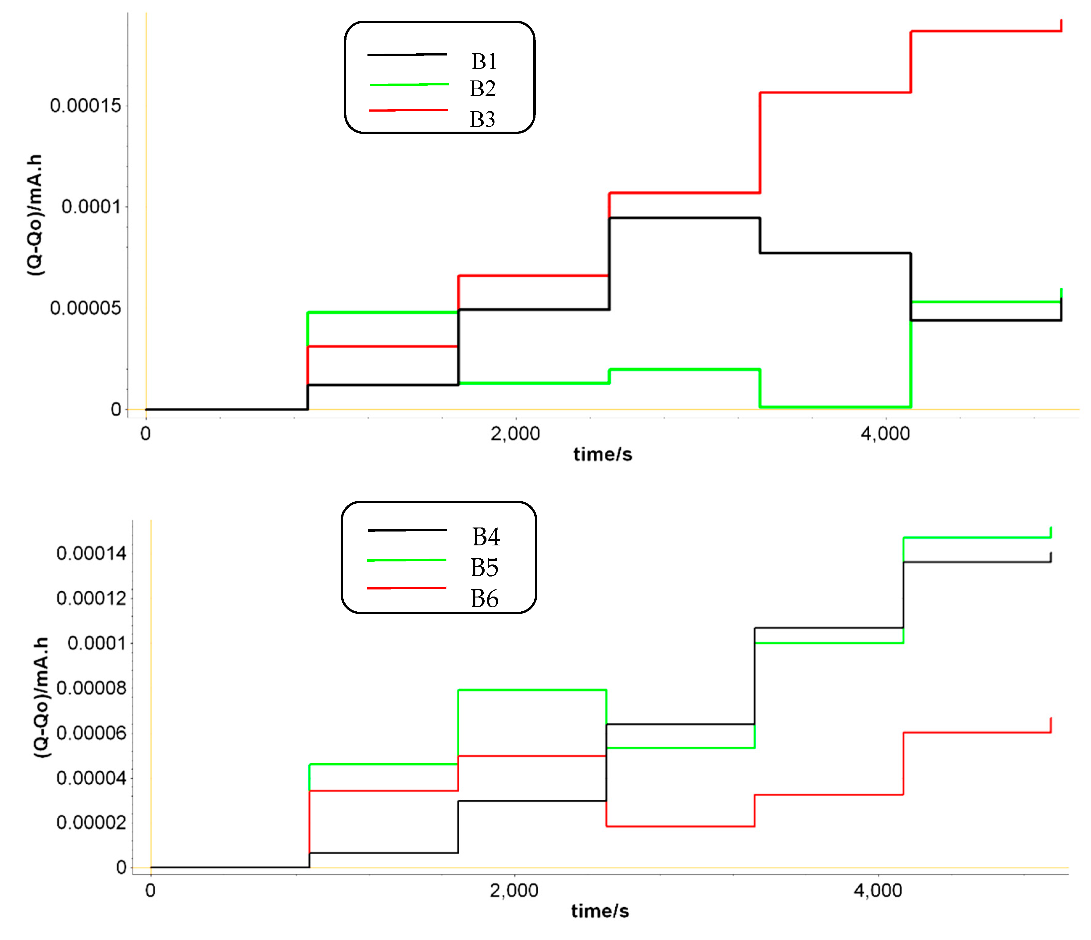
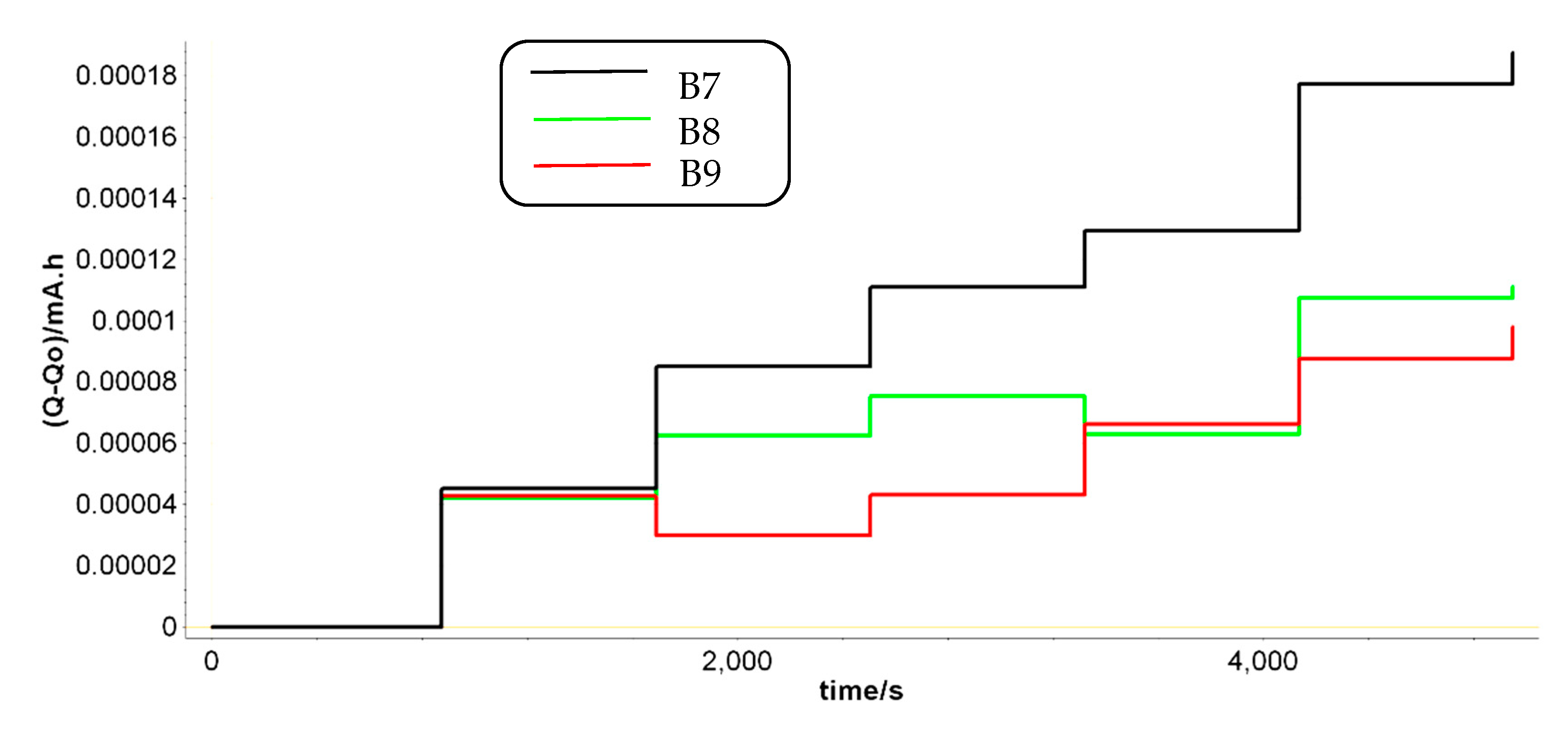
During PEIS, a small sinusoidal signal is applied around a DC potential in the frequency range 0.2-200 Hz. The amplitude of this voltage signal was set to 3 mV. If we look at
Figure 5, some of the batteries have a growing trend of the charge, which means that during PEIS the charge tends to accumulate in the battery. Due to the low impedance of LABs batteries, this can lead to a battery overcharge that accelerates the degradation of the battery [
44,
45].
Another specificity in
Figure 5 is that the LABs with the longer cycle life have a reduced charge growth during the PEIS cycles. Under the same PEIS conditions, batteries B2, B6 and B9 also experience charge decrease, that ultimately balance the total charge in the batteries and increase their lifetime performance. This is in agreement with the results described in
Table 1, in terms of maximum number of discharging cycles (in blue)
vs the capacity fluctuations. By analyzing how much capacity has been loosed in time during the discharging cycling in all prototypes, we can easily observe that the lower fluctuations in capacity are coming from batteries B2, B6 and B9, the best performant ones.
3.2. Q1 element data analysis as SoH indicator
A particular attention has been addressed to the constant phase element (CPE) fluctuations, as this parameter was found essential for a good quality fit over an extended range of batteries [
40,
41,
42,
43]. Thus, we have investigated the dependence of the values for components of the equivalent Randle circuit shown in
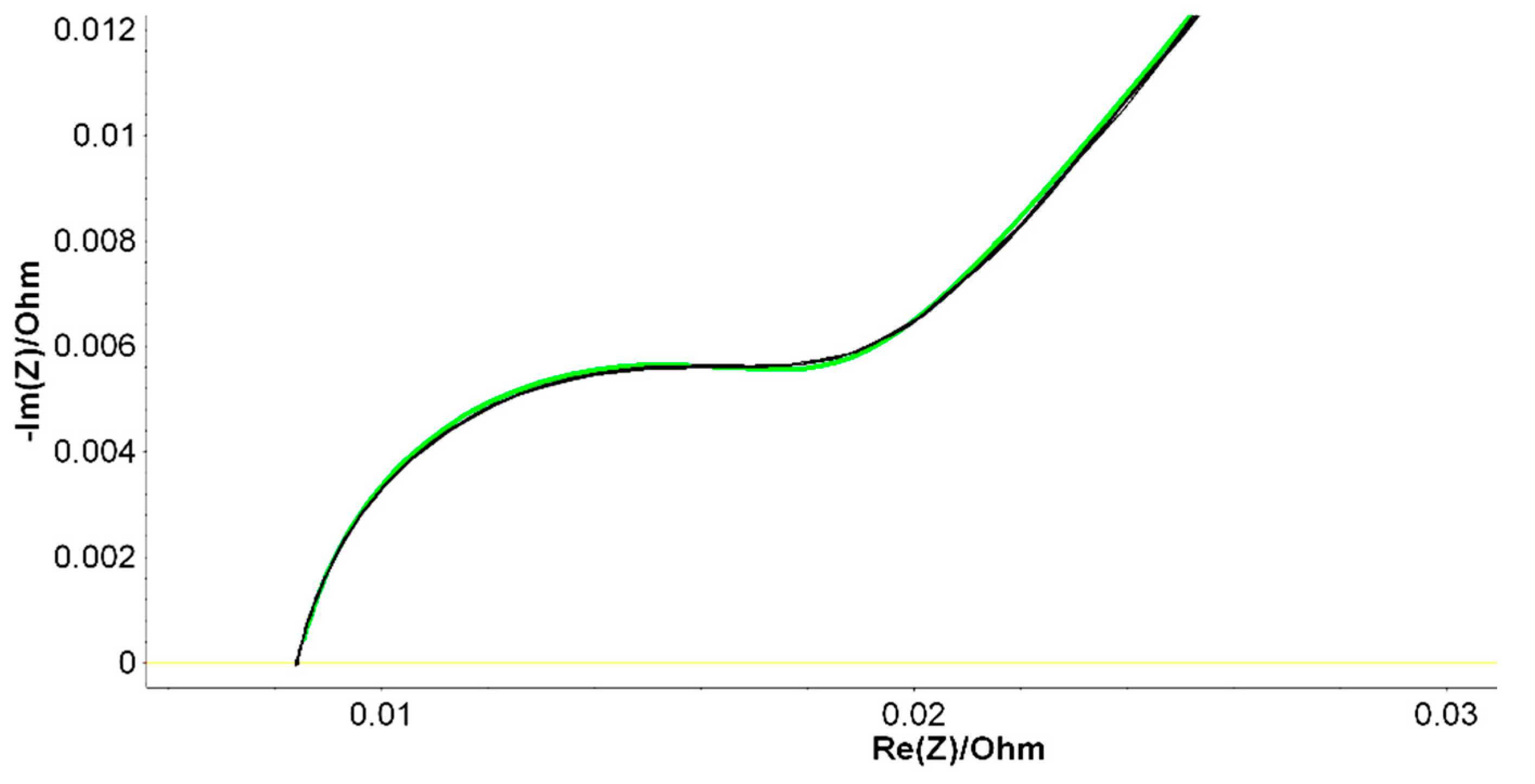
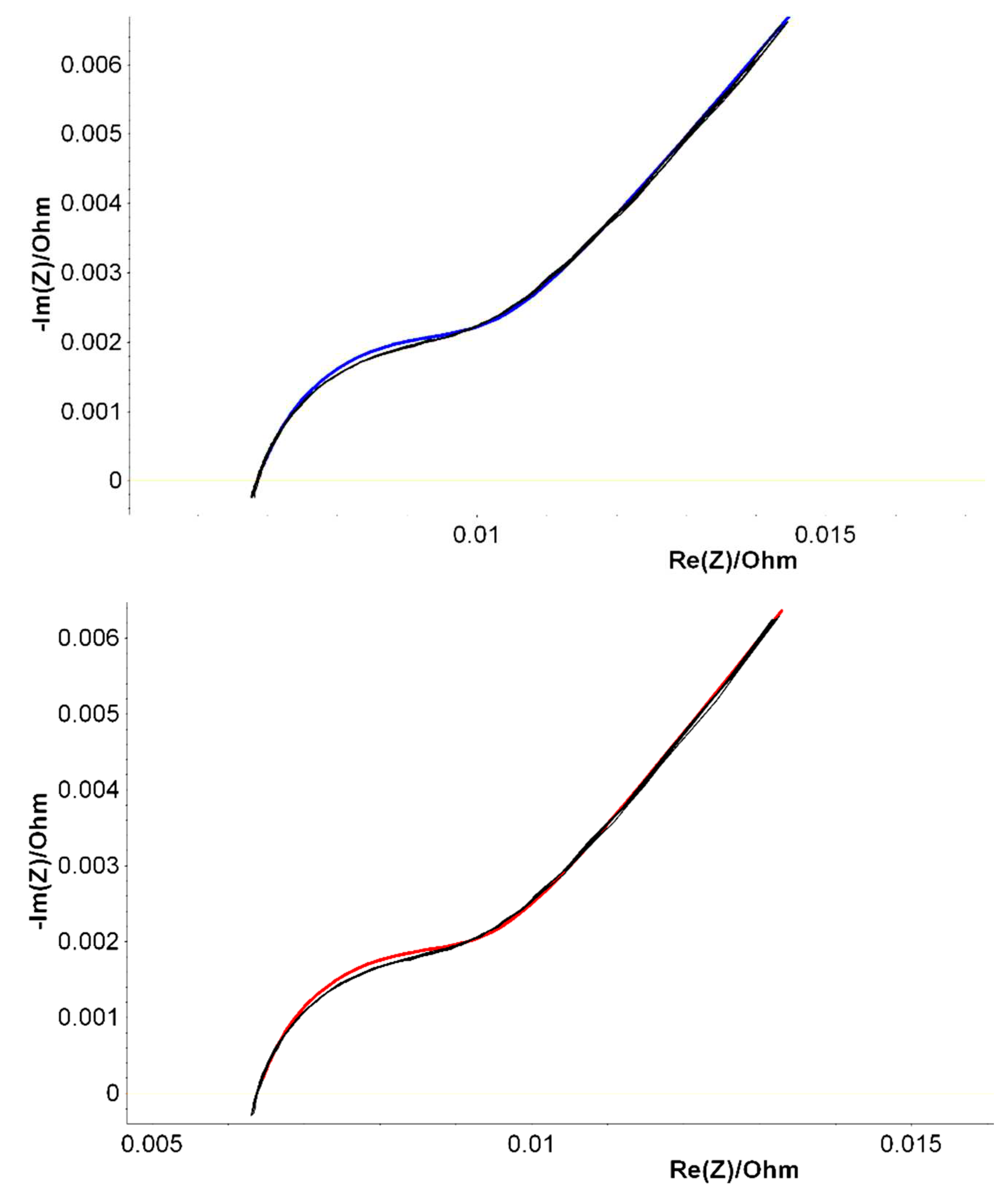
Figure 4. The results of PEIS analysis are shown in
Figure 6 in which the Nyquist diagrams within their fitting curves were measured immediately after fabrication for B2, B6 and B9 LABs prototypes. Similar diagrams were resulted for 50% DoD partially discharged batteries, aged at ROMBAT. We have included in
Table 2, the averaged values of all the measured Randles equivalent electrical circuit parameters, within the aim to investigate which parameter is fluctuating the most in order to offer a predictable trend of the battery’s lifetime performance.
As a second purpose, we tried to see if our methodological approaches which were applied previously on various LABs characterization [
41,
42,
43] are confirmed, even if the manner of measurement is different: the batteries cycling is industrially controlled and just two measurements are made. As we have already seen in our previous works, a linear decay of Q occurs in their second half period. However, is a different situation now, when we performed PEIS measurements just on two particular phases (at the beginning and at the end of life), not on the entire spectrum of the charging/discharging cycling.
We summarized in
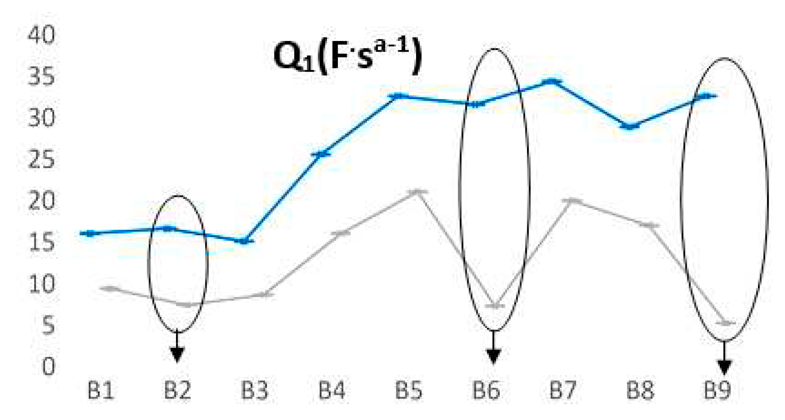
Figure 7 the most relevant fluctuations of Q
1 parameter. For batteries that have a longer life, a smaller value of the Q
1 parameter is observed when batteries are discharged, thus increasing significantly the length difference between the two states (we encircled around B2, B6 and B9). Even for B2 prototype, the trend is confirmed, in which the discharging cycles are quite appropriate for all three L2 FLO 52 Ah type/technology, while for B6 -L2 EFB 60 Ah and B9 – L3 EFB 70 Ah batteries, this range is obviously much longer. This means that at each point of measurement, we can forecast the battery lifespan, taking into account the two limits of Q
1 values for each type technology.
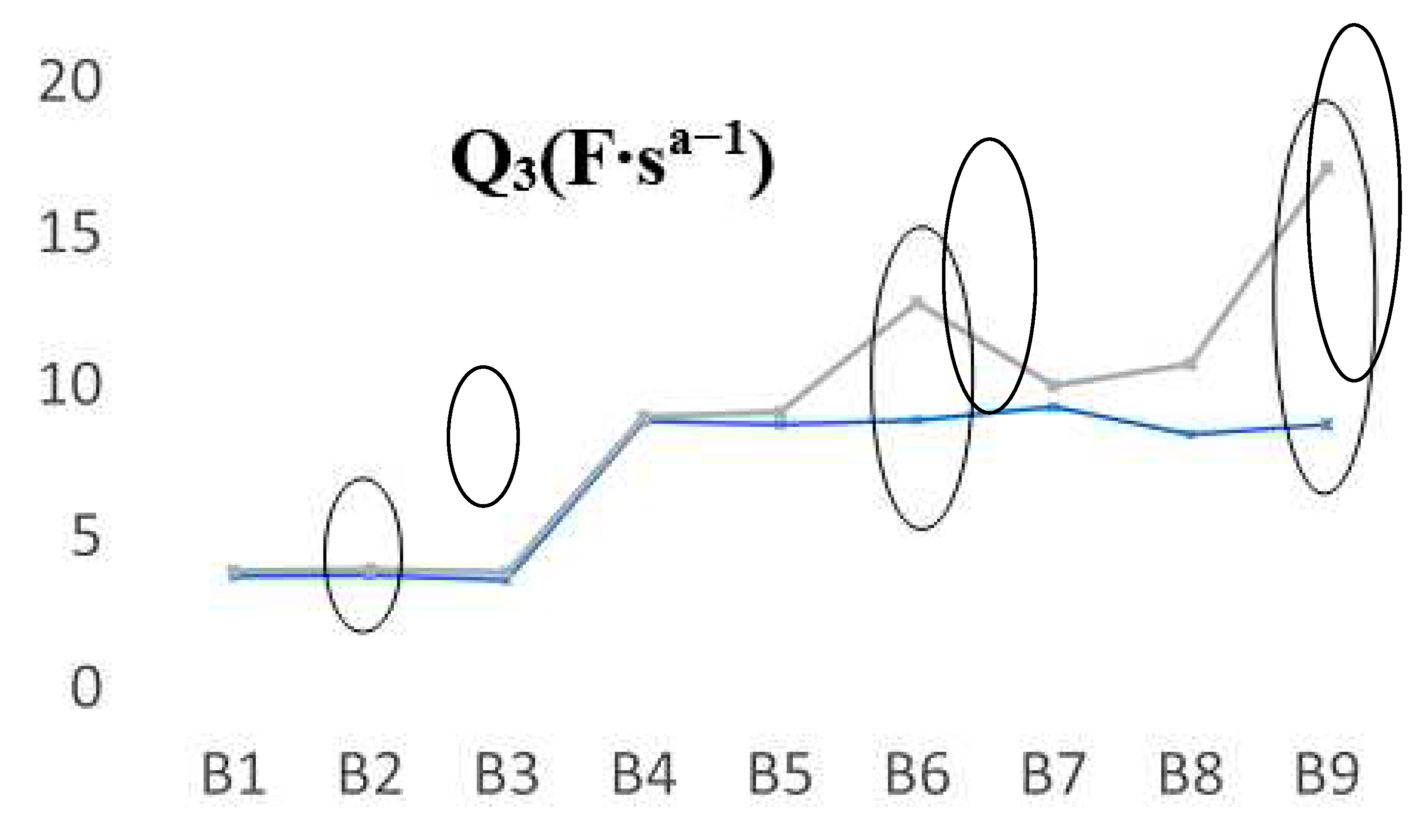
Going further, we have seen another fluctuation that appears in the case of Q
3 parameter, which also highlight some predictable aging trends, in opposite direction to Q
1. In
Figure 8, are shown the registered values of Q
3 parameter when the batteries are new and aged. In this case, for FLO 52 Ah batteries, the B2 behavior is very similar in all cases, thus we can assume that a possible explanation of the values obtained for Q
3 is due to the decrease in the amount of electrolyte. However, their discharging cycling has shown close values. For B6 and B9 prototypes, in the discharging cycles a significant shift appears, in particular for the last battery, that has been the most performant type as we can see from
table 1. It seems that there is a direct correlation between Q elements (Q
1 and/or Q
3) and the phenomena which occurs near to the electrodes in which clear fluctuations of the capacity (linked to the double layer) appears due to some possible distinct planarity imperfections, rugosity, or to the undesirable chemical processes that take place when a battery is constantly charged and drained.
3.3. Resonance frequency analysis
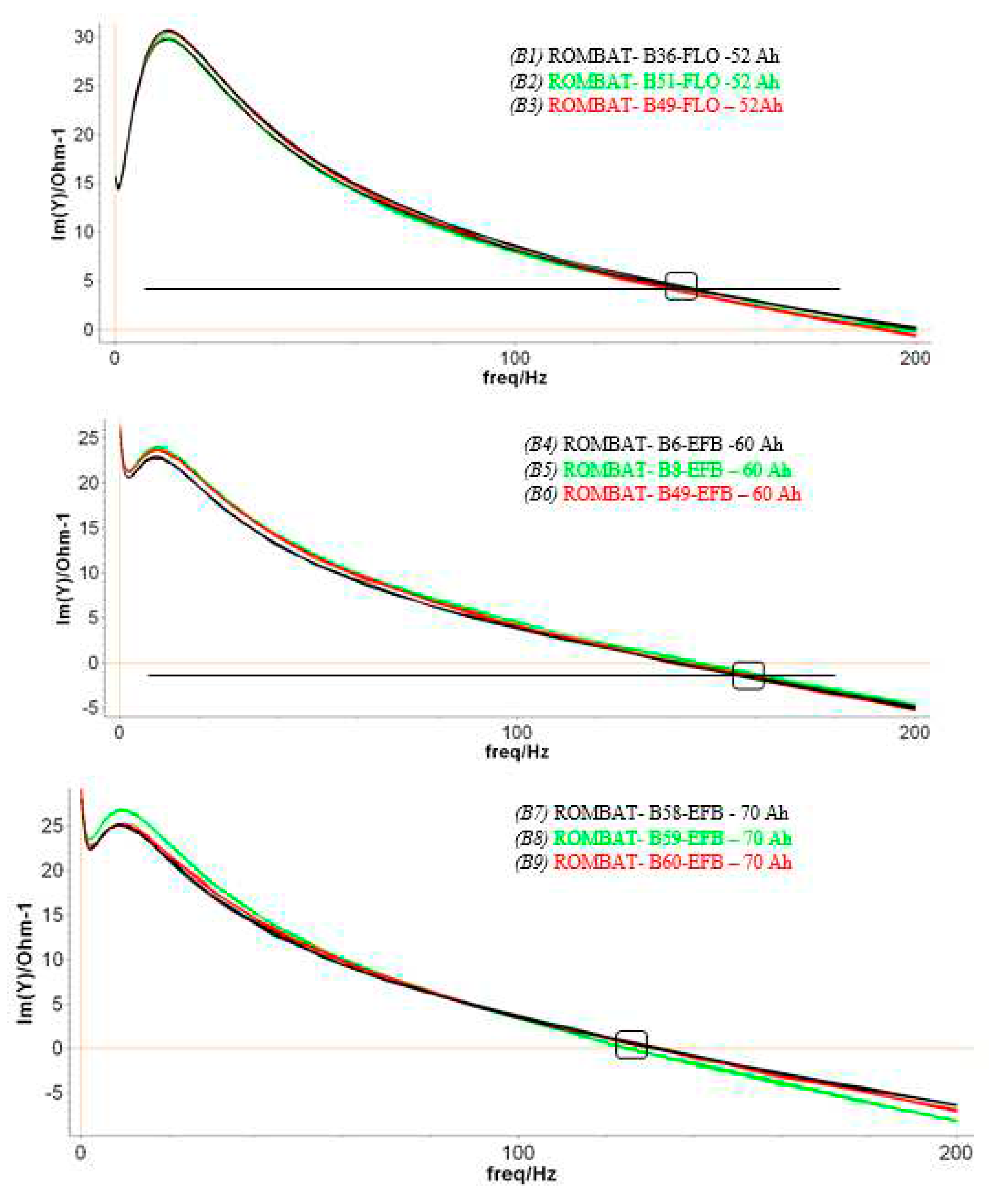
Following the impedance plots vs frequency diagrams, when fully charged, we measured the batteries SoH by monitoring one particular parameter, the resonant frequency of the circuit, without any fitting of equivalent circuit or parameters interpretations. This approach was successfully used by us in previous works [
40,
42], within reliable results on predicting the LABs lifetime performance. The aim was to offer a qualitative frame of how electronic measurements can fill up the chemical data.
The results presented in
Figure 9 are corresponding to the first phase of the experiment, while in a second stage, a similar approach was made after the batteries were aged at ROMBAT factory, to 50% DoD. We have regularly discharged the batteries at a lower percentage amount than to drain the battery to its maximum DoD, in order to get more charging/discharging cycles, and consequently, to prolong the battery lifetime.
We summarized in
Table 3 the resonance frequencies obtained on the three sets of the new and aged batteries. An average of the resonance frequency values was applied for each battery type/technology. Moreover, the maximum number of discharging cycles (in blue) and the minimum number of discharging cycles (in red) are shown for each batteries type in order to correlate them as a prediction factor in the LABs lifetime.
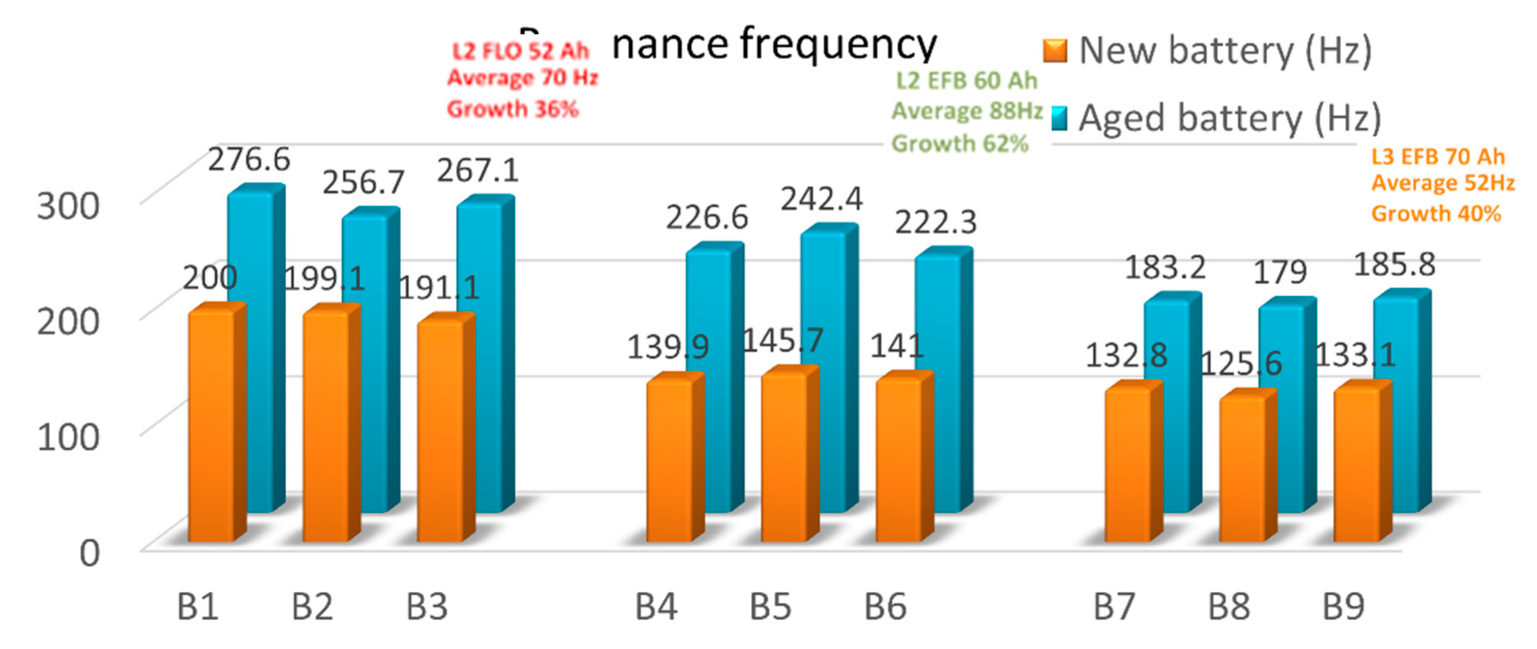
For a better visualization, we illustrate in
Figure 10, the resonance frequency increment in both charged and end of life batteries, together with their averaged frequencies and growth percentage. As can be seen, an upward trend in the frequency values has been obtained in all the cases. Depending on the way the batteries are manufactured (type and/or technology), the increase in resonance frequency appears in all cases, for each battery, from new to used batteries. The average increment of resonance frequency is different in all cases, from 70 Hz of L2 FLO 52 Ah B1-B3 type, to 88 Hz of L2 EFB 60 Ah B3-B6 type or 52 Hz for L3 EFB 70 Ah B6-B9 type. Thus, we can assume that the 50% DoD cycling is ending when resonance frequency increase with 36% for the first batteries package, 62% for the second package, and 40% for the last batteries type/technology.
For example, if we consider the first batteries type of L2 FLO 52 Ah, we can see that for B2 prototype an increment of 57.6 Hz between the two phases highlight the longest cycle life. If this difference increase, as in the case of B1 and B3, the aging of the battery is faster. For the L2 EFB 60 Ah type, we can observe that an 81.3 Hz difference between the measurements, highlight an impressive number of 228 charging/discharging cycles until the battery is out of service. Again, when difference increase, as for B4 and B5, the cycle life of the batteries decreases, in this case dramatically, with ~ 4 time less than B6 accumulator. The last package of L3 EFB 70 Ah, shows that for B9, optimum differences of 52.7 Hz describe the best performance of B9 battery prototype, with 254 charging/discharging cycles. B7 and B8 batteries type describe a much shorter cycle life, with just 23 charging/discharging cycles, even if the differences in absolute value between the new and used tested batteries are quite near. However, because this analysis is made in just two specific SoC stages, at the beginning and at the end of LABs life, it is quite hard to offer a qualitative trend prediction of a particular battery prototype.
4. Conclusion
We combined here the controlled aging of 9 LABs prototypes with the EIS measurements, in order to highlight the connection between their SoH vs electric response. Since we were focused on finding a straight and reliable evaluation of lead-acid accumulators, we decided to use the EIS analysis of (Q-Q0) total charge fluctuations after fabrication, the decay values of CPE in two phases: at the beginning and the end of life, and the resonance frequency modifications.
In which concern the first approach, the level of charge after each PEIS measurement has been registered in terms of (Q-Q0) total charge exchanged. By analyzing the amount of the capacity which has been loosed in time during the discharging cycling in all prototypes, we observed that the lower fluctuations in capacity are coming from batteries B2, B6 and B9, the best performant ones.
In the second approach, we focused on the CPE element analysis, as a fundamental quality fit parameter of EIS data. The prevalence of capacitance was studied in the light of the non-ideally polarized electrodes, thus assessing the modifications that appear on the CPE usage. Immediately after fabrication, at 100% SoC, the fit applied to Randles equivalent parameters cannot provide a viable trend able to predict the LABs lifespan, for any of the battery’s type/technology. At the end of life, a clear modification of the CPE parameter allows a qualitative analysis capable to provide the decay of the battery SoH. All the other values of the measured equivalent circuit parameters remain constant, within two exceptions, the Q1 and Q3. The asymmetric behaviour of these elements is probably caused by the sulphating effects that are quite strong in the lead-acid plates during the charging/discharging cycles. Our data suggest that this behavior can be directly associated to the manufacturing quality and/or technology of the batteries. The producers can establish the quality of the LABs from the slopes of the Q1 and Q3 at the end of life, thus allowing to analyse the validity of technological innovations which may lead to the increment of the battery’s lifetime. This typical behaviour of Q1 and respectively Q3, occurs in the second part of the battery lifetime, being associate to a qualitative factor in batteries fabrication. The length distances between Q values, are very similar for the three B2, B6 and B9 batteries, suggesting that this is a characteristic of the battery performance. By discharging cycling, we know that these prototypes are performing the best, depending on their type/technology, and there the producers can assess the LABs quality from the slopes of Q at the end of life.
By analysing the single resonance frequency parameter in the two phases, we have seen that the DoD cycling is ending, when resonance frequency increase with 36% for the first batteries package, 62% for the second package, and 40% for the last batteries type/technology. Moreover, for LABs at 100% SoC, the degradation of the battery is leading to more important variations of resonance frequency, while for LABs aged at 50% DoD, smaller fluctuations occurred. This can possibly suggest that the concentration of lead sulphate in LABs prototypes as well as their physical parameters are significant in establishing the resonance frequency, since the effect of charging/discharging cycling is to decrease/increase its content. This data allows us to predict when LABs aged with 50% DoD arrive at the end of life, in function of their type and/or manufacturing procedure. Based on these perspectives, we can perform an early prediction of batteries lifespan, at each moment of discharging, and by consequence, which type/technology emphasize the best performance.
Acknowledgments
This paper was financially supported from the PN-III-P2-2.1-PED- 2021-0936 project, No. 715 PED/2022 and the MCID Core Programme within the National Plan for Research Development and Innovation 2022-2027 project PN 23 24 01 04.
References
- Pavlov, D. Lead-acid Batteries Science and Technology; Elsevier: Oxford, UK, 2011; ISBN 9780444528827. [Google Scholar]
- Kurzweil, P. Gaston Plante and his invention of the lead-acid battery - the genesis of the first practical rechargeable battery. J. Power Sources 2010, 195, 4424–4434. [Google Scholar] [CrossRef]
- May, G. J.; Davidson, A.; Monahov, B. Lead batteries for utility energy storage: a review. Journal of Energy Storage 2018, 15, 145–157. [Google Scholar] [CrossRef]
- Garche, J.; Moseley, P. T.; Karden, E. 5-Lead–acid batteries for hybrid electric vehicles and battery electric vehicles, Advances in Battery Technologies for Electric Vehicles. Woodhead Publishing Series in Energy 2015, 75–101. [Google Scholar]
- Garche, J. On the historical development of the lead/acid battery, especially in Europe. J. Power Sources 1990, 31, 401–406. [Google Scholar] [CrossRef]
- Available online: https://www.global.toshiba/ww/products-solutions/battery/scib/application/drone.html.
- Available online: https://www.medicaldevice-network.com/contractors/electronics/wyon-medical-batteries/.
- Yanamandra, K.; Pinisetty, D.; Daoud, A.; Gupta, N. Recycling of Li-Ion and Lead Acid Batteries: A Review. J. Indian Inst. Sci. 2022, 102, 281–295. [Google Scholar] [CrossRef]
- Available online: https://www.fortunebusinessinsights.com/industry-reports/lead-acid-battery-market-100237.
- Jolly, R.; Rhin, C. The recycling of lead-acid batteries: production of lead and polypropylene. Resour. Conserv. Recycl. 1994, 10, 137–143. [Google Scholar] [CrossRef]
- Lambert, D.W.H. Manders, J.E. Nelson, R.F. Peters, K. Strategies for enhancing lead-acid battery production and performance. J. Power Sources 2000, 88, 130–147. [Google Scholar] [CrossRef]
- Szymborski, J.; Eggers, M. L. Development of a totally maintenance free lead-acid battery for telecommunications standby power. Solar & Wind Technology 1985, 2, 133–137. [Google Scholar]
- Albers, J. Heat tolerance of automotive lead-acid batteries. Journal of Power Sources 2009, 190, 162–172. [Google Scholar] [CrossRef]
- Available online: https://www.electronics-notes.com/articles/electronic _ components/ battery-technology/how-do-lead-acid-batteries-work-technology.php.
- Available online: https://www.internationaltin.org/wp-content/uploads/2018/03/.
- Bogno, B. , Sawicki, J. P., Salame, T., Aillerie, M., Saint-Eve, F., Hamandjoda, O.; Tibi, B. Improvement of safety, longevity, and performance of lead acid battery in off-grid PV systems. Int. J. Hydrogen Energy 2017, 42, 3466–3478. [Google Scholar] [CrossRef]
- Alzieu, J.; Smimite, H.; Glaize, D. Improvement of intelligent battery controller: state-of-charge indicator and associated functions. J. Power Sources 1997, 67, 157–161. [Google Scholar] [CrossRef]
- Piller, S.; Perrin, M.; Jossen, A. Methods for state-of-charge determination and their applications. J. Power Sources 2001, 9, 113–120. [Google Scholar] [CrossRef]
- Salkind, A. J.; Fennie, C.; Singh, P.; Atwater, T.; Reisner, D.E. Determination of state-of-charge and state-of-health of batteries by fuzzy logic methodology. J. Power Sources 1999, 80, 293–300. [Google Scholar] [CrossRef]
- Al Hadi, A.M.R.; Ekaputri, C.; Estimating, M.R. the state of charge on lead acid battery using the open circuit voltage method. J. Phys. Conf. Ser. 2019, 1367, 012077. [Google Scholar] [CrossRef]
- Wang, Z.-H.; Hendrick; Horng, G. -J.; Wu, H.-T.; Jong, G.-J. A prediction method for voltage and lifetime of lead–acid battery by using machine learning. Energy Exploration & Exploitation 2019, 38, 310–329. [Google Scholar]
- de Sousa, T.T.; Arioli, V.T.; Vieira, C.S.; dos Santos, S.R.; França, A.P. Comparison of different approaches for lead acid battery state of health estimation based on artificial neural networks algorithms. In Proceedings of the 2016 IEEE Conference on Evolving and Adaptive Intelligent Systems (EAIS), Natal, Brazil, 23–25 May 2016. [Google Scholar]
- Hemdani, J.; Degaa, L.; Soltani, M.; Rizoug, N.; Telmoudi, A. J.; Chaari, A. Battery Lifetime Prediction via Neural Networks with Discharge Capacity and State of Health. Energies 2022, 15, 8558. [Google Scholar] [CrossRef]
- Freitas, D. S.; Hugerles, C. N.; Edson, A.L. Parameter estimation of a lead-acid battery model using genetic algorithm. Journal of Mechatronics Engineering 2019, 2, 2–7. [Google Scholar] [CrossRef]
- Mekonnen, Y.; Aburbu, H.; Sarwat, A. Life cycle prediction of Sealed Lead Acid batteries based on a Weibull model. J. Energy Storage 2018, 18, 467–475. [Google Scholar] [CrossRef]
- Hlal, M. I.; Ramachandaramurthy, V. K.; Sarhan, A.; Pouryekta, A.; Subramaniam, U. Optimum battery depth of discharge for off-grid solar PV/battery system. J. Energy Storage 2019, 26, 100999. [Google Scholar] [CrossRef]
- Křivík, P.; Bača, P.; Kazelle, J. Effect of ageing on the impedance of the lead-acid battery. J. Energy Storage 2021, 36, 102382. [Google Scholar] [CrossRef]
- Murariu, T.; Morari, C. Time-dependent analysis of the state-of-health for lead-acid batteries: an EIS study. J. Energy Storage 2019, 21, 87–93. [Google Scholar] [CrossRef]
- Garche, J.; Karden, E.; Moseley, P.T.; Rand, D. A. J. Lead-Acid Batteries for Future Automobiles; Elsevier: Amsterdam, The Netherlands, 2017; p. 597. [Google Scholar]
- Available online: https://www.en-standard.eu/bs-en-50342-1-2015-a2-2021-lead-acid-starter-batteries-general-requirements-and-methods-of-test/.
- Barsoukov, E.; Ross Macdonald, J. Impedance spectroscopy; John Wiley & Sons: Hoboken, NJ, USA, 2005; ISBN 0-471-64749-7. [Google Scholar]
- Rahmanifar, M.S. Enhancing the cycle life of Lead-acid batteries by modifying negative grid surface. Electrochim. Acta 2017, 235, 10–18. [Google Scholar] [CrossRef]
- Kirchev, A.; Delaille, A.; Perrin, M.; Lemaire, E.; Mattera, F. Studies of the pulse charge of lead-acid batteries for PV applications part II. Impedance of the positive plate revisited. J. Power Sources 2007, 170, 495–512. [Google Scholar] [CrossRef]
- Huet, F. A review of impedance measurements for determination of the state-of charge or state-of-health of secondary batteries. J. Power Sources 1998, 70, 59–69. [Google Scholar] [CrossRef]
- Kirchev, A.; Delaille, A.; Perrin, M.; Lemaire, E.; Mattera, F. Studies of the pulse charge of lead-acid batteries for PV applications part III. Electrolyte concentration effects on the electrochemical performance of the positive plate. J. Power Sources 2008, 179, 808–818. [Google Scholar] [CrossRef]
- Bard, A.; Faulkner, L.R. Electrochemical Methods: Fundamental and Applications; John Wiley & Sons Inc.: Hoboken, NJ, USA, 2001; ISBN 0-471-04372-9. [Google Scholar]
- Badeda, J.; Kwiecien, M.; Schulte, D.; Sauer, D.U. Battery state estimation for lead acid batteries under float charge conditions by impedance: benchmark of common detection methods. Appl. Sci. 2018, 8, 1308. [Google Scholar] [CrossRef]
- Available online: www.rombat.ro.
- Available online: https://www.ecosoch.com/lead-acid-battery/.
- Calborean, A.; Murariu, T.; Morari, C. Determination of current homogeneity on the electrodes of lead-acid batteries through electrochemical impedance spectroscopy. Electrochimica Acta 2019, 320, 134636. [Google Scholar] [CrossRef]
- Calborean, A.; Bruj, O.; Murariu, T.; Morari, C. Resonance frequency analysis of lead-acid cells: an EIS approach to predict the state-of-health. J. Energy Storage 2020, 27, 101143. [Google Scholar] [CrossRef]
- Calborean, A.; Murariu, T.; Morari, C. Optimized lead-acid grid architectures for automotive lead-acid batteries: An electrochemical analysis. Electrochimica Acta 2021, 372, 137880. [Google Scholar] [CrossRef]
- Calborean, A.; Bruj, O.; Morari, C. Leaf and hexagonal grid designs for lead-acid battery. An EIS analysis Journal of Energy Storage 2022, 56, 105933. [Google Scholar] [CrossRef]
- Available online: https://savree.com/en/encyclopedia/flooded-lead-acid-battery.
- Ouyang, D.; Weng, J.; Chen, M.; Wang, J.; Wang, Z. Sensitivities of lithium-ion batteries with different capacities to overcharge/over-discharge. Journal of Energy Storage 2022, 52, 104997. [Google Scholar] [CrossRef]
- Ren, D.; Feng, X.; Lu, L.; He, X.; Ouyang, M. Overcharge behaviors and failure mechanism of lithium-ion batteries under different test conditions. Applied Energy 2019, 250, 323–332. [Google Scholar] [CrossRef]
|
Disclaimer/Publisher’s Note: The statements, opinions and data contained in all publications are solely those of the individual author(s) and contributor(s) and not of MDPI and/or the editor(s). MDPI and/or the editor(s) disclaim responsibility for any injury to people or property resulting from any ideas, methods, instructions or products referred to in the content. |
© 2023 by the authors. Licensee MDPI, Basel, Switzerland. This article is an open access article distributed under the terms and conditions of the Creative Commons Attribution (CC BY) license (http://creativecommons.org/licenses/by/4.0/).


