Submitted:
10 November 2023
Posted:
13 November 2023
You are already at the latest version
Abstract
Keywords:
1. Introduction
2. Materials and Methods
3. Results
3.1. The TP901-1 capsid
3.2. The procapsid scaffolding protein
3.3. Dodecameric portal and adaptor and the hexameric stopper.
3.3.1. The dodecameric portal (ORF32)
3.3.2. The dodecameric adaptor (ORF 38)
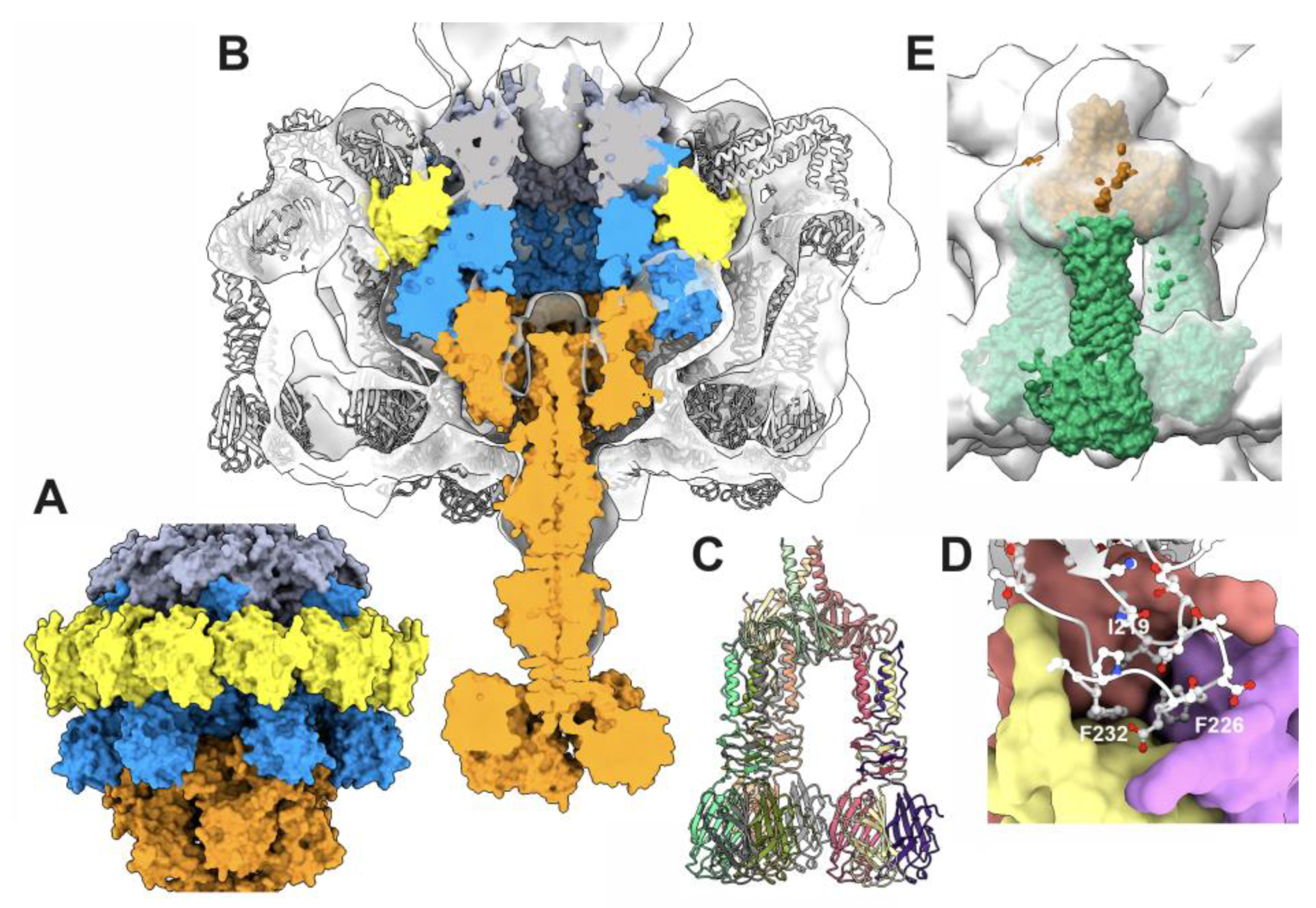
3.3.3. The portal/adaptor complex
3.3.4. The adaptor/stopper (ORF39 complex
3.3.5. The collar and the neck passage proteins
3.4. The neck/tail junction and the tail
3.4.1. The stopper/tail terminator (TT; ORF41) complex
3.4.2. The tail terminator (TT) / major tail protein (MTP; ORF42) complex
3.4.3. The MTP/MTP rings
3.5. The baseplate
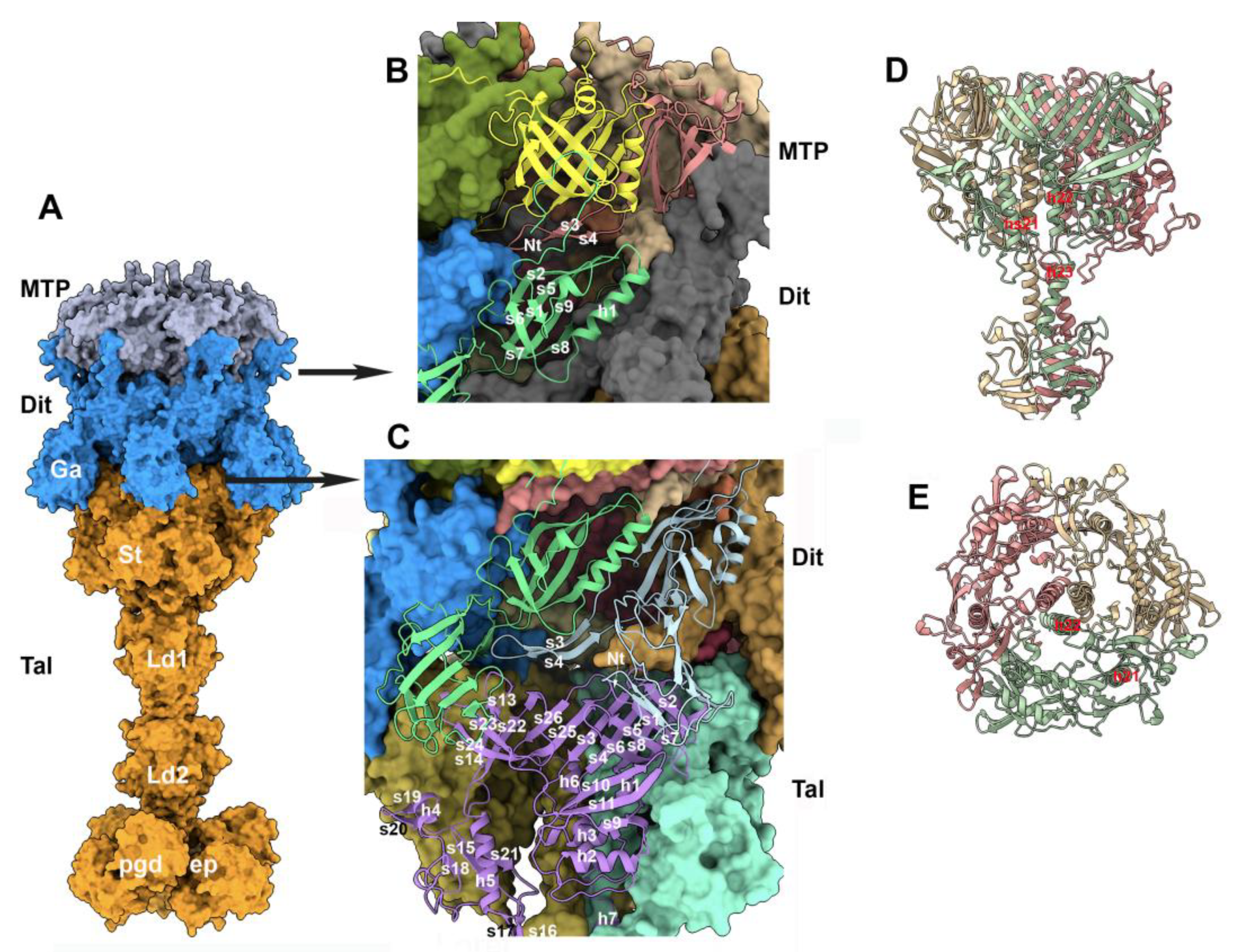
3.5.1. The MTP/Dit interface
3.5.2. The trimeric Tal and the Dit/Tal interface
3.5.3. The Dit/BppU and BppU/RBP complexes
4. Discussion
Supplementary Materials
Author Contributions
Funding
Data Availability Statement
Acknowledgments
Conflicts of Interest
References
- Ackermann, H. W. "Bacteriophage Electron Microscopy.". Adv Virus Res 2012, 82, 1–32. [Google Scholar]
- Turner, D., A. N. Shkoporov, C. Lood, A. D. Millard, B. E. Dutilh, P. Alfenas-Zerbini, L. J. van Zyl, R. K. Aziz, H. M. Oksanen, M. M. Poranen, A. M. Kropinski, J. Barylski, J. R. Brister, N. Chanisvili, R. A. Edwards, F. Enault, A. Gillis, P. Knezevic, M. Krupovic, I. Kurtboke, A. Kushkina, R. Lavigne, S. Lehman, M. Lobocka, C. Moraru, A. Moreno Switt, V. Morozova, J. Nakavuma, A. Reyes Munoz, J. Rumnieks, B. L. Sarkar, M. B. Sullivan, J. Uchiyama, J. Wittmann, T. Yigang, and E. M. Adriaenssens. "Abolishment of Morphology-Based Taxa and Change to Binomial Species Names: 2022 Taxonomy Update of the Ictv Bacterial Viruses Subcommittee." Arch Virol 168, no. 2 (2023): 74. [CrossRef]
- Comeau, A. M., D. Tremblay, S. Moineau, T. Rattei, A. I. Kushkina, F. I. Tovkach, H. M. Krisch, and H. W. Ackermann. "Phage Morphology Recapitulates Phylogeny: The Comparative Genomics of a New Group of Myoviruses." PLoS One 7, no. 7 (2012): e40102. [CrossRef]
- Goulet, A., S. Spinelli, J. Mahony, and C. Cambillau. "Conserved and Diverse Traits of Adhesion Devices from Siphoviridae Recognizing Proteinaceous or Saccharidic Receptors." Viruses 12, no. 5 (2020). [CrossRef]
- Veesler, D., S. Spinelli, J. Mahony, J. Lichiere, S. Blangy, G. Bricogne, P. Legrand, M. Ortiz-Lombardia, V. Campanacci, D. van Sinderen, and C. Cambillau. "Structure of the Phage Tp901-1 1.8 Mda Baseplate Suggests an Alternative Host Adhesion Mechanism." Proc Natl Acad Sci U S A 109, no. 23 (2012): 8954-8. [CrossRef]
- Lavelle, K., Goulet, A., McDonnel, B., Spinelli, S., van Sinderen, D., Mahony, J. and Cambillau, C. "Revisiting the Host Adhesion Determinants of Streptococcus Thermophilus Siphophages." Microb. Biotech. 13, no. 6 (2020): 1765-79. [CrossRef]
- Bebeacua, C., D. Tremblay, C. Farenc, M. P. Chapot-Chartier, I. Sadovskaya, M. van Heel, D. Veesler, S. Moineau, and C. Cambillau. "Structure, Adsorption to Host, and Infection Mechanism of Virulent Lactococcal Phage P2." J Virol 87, no. 22 (2013): 12302-12. [CrossRef]
- Baptista, C., M. A. Santos, and C. Sao-Jose. "Phage Spp1 Reversible Adsorption to Bacillus Subtilis Cell Wall Teichoic Acids Accelerates Virus Recognition of Membrane Receptor Yueb." J Bacteriol 190, no. 14 (2008): 4989-96. [CrossRef]
- Xu, J., R. W. Hendrix, and R. L. Duda. "Chaperone-Protein Interactions That Mediate Assembly of the Bacteriophage Lambda Tail to the Correct Length." J Mol Biol 426, no. 5 (2014): 1004-18. [CrossRef]
- Degroux, S., G. Effantin, R. Linares, G. Schoehn, and C. Breyton. "Deciphering Bacteriophage T5 Host Recognition Mechanism and Infection Trigger." J Virol 97, no. 3 (2023): e0158422. [CrossRef]
- Mahony, J., S. R. Stockdale, B. Collins, S. Spinelli, F. P. Douillard, C. Cambillau, and D. van Sinderen. "Lactococcus Lactis Phage Tp901-1 as a Model for Siphoviridae Virion Assembly.". Bacteriophage 2016, 6, e1123795. [Google Scholar] [CrossRef] [PubMed]
- Fokine, A., and M. G. Rossmann. "Molecular Architecture of Tailed Double-Stranded DNA Phages." Bacteriophage 4, no. 1 (2014): e28281. [CrossRef]
- Spinelli, S., C. Bebeacua, I. Orlov, D. Tremblay, B. P. Klaholz, S. Moineau, and C. Cambillau. "Cryo-Electron Microscopy Structure of Lactococcal Siphophage 1358 Virion." J Virol 88, no. 16 (2014): 8900-10. [CrossRef]
- Goulet, A., R. Joos, K. Lavelle, D. Van Sinderen, J. Mahony, and C. Cambillau. "A Structural Discovery Journey of Streptococcal Phages Adhesion Devices by Alphafold2." Front Mol Biosci 9 (2022): 960325. [CrossRef]
- Veesler, D., and C. Cambillau. "A Common Evolutionary Origin for Tailed-Bacteriophage Functional Modules and Bacterial Machineries." Microbiol Mol Biol Rev 75, no. 3 (2011): 423-33, first page of table of contents. [CrossRef]
- Ruiz-Cruz, S., A. Erazo Garzon, P. Kelleher, F. Bottacini, S. O. Breum, H. Neve, K. J. Heller, F. K. Vogensen, S. Palussiere, P. Courtin, M. P. Chapot-Chartier, E. Vinogradov, I. Sadovskaya, J. Mahony, and D. van Sinderen. "Host Genetic Requirements for DNA Release of Lactococcal Phage Tp901-1." Microb Biotechnol 15, no. 12 (2022): 2875-89. [CrossRef]
- Stockdale, S. R., B. Collins, S. Spinelli, F. P. Douillard, J. Mahony, C. Cambillau, and D. van Sinderen. "Structure and Assembly of Tp901-1 Virion Unveiled by Mutagenesis." PLoS One 10, no. 7 (2015): e0131676. [CrossRef]
- Ostergaard Breum, S., H. Neve, K. J. Heller, and F. K. Vogensen. "Temperate Phages Tp901-1 and Philc3, Belonging to the P335 Species, Apparently Use Different Pathways for DNA Injection in Lactococcus Lactis Subsp. Cremoris 3107.". FEMS Microbiol Lett 2007, 276, 156–64. [Google Scholar] [CrossRef] [PubMed]
- Rasmussen, K. K., A. Palencia, A. K. Varming, H. El-Wali, E. Boeri Erba, M. Blackledge, K. Hammer, T. Herrmann, M. Kilstrup, L. Lo Leggio, and M. R. Jensen. "Revealing the Mechanism of Repressor Inactivation During Switching of a Temperate Bacteriophage." Proc Natl Acad Sci U S A 117, no. 34 (2020): 20576-85. [CrossRef]
- Pedersen, M., J. T. Neergaard, J. Cassias, K. K. Rasmussen, L. Lo Leggio, K. Sneppen, K. Hammer, and M. Kilstrup. "Repression of the Lysogenic P(R) Promoter in Bacteriophage Tp901-1 through Binding of a Ci-Mor Complex to a Composite O(M)-O(R) Operator.". Sci Rep 2020, 10, 8659. [Google Scholar] [CrossRef] [PubMed]
- Varming, A. K., K. K. Rasmussen, Z. Zong, P. W. Thulstrup, M. Kilstrup, and L. Lo Leggio. "Flexible Linker Modulates the Binding Affinity of the Tp901-1 Ci Phage Repressor to DNA." FEBS J 289, no. 4 (2022): 1135-48. [CrossRef]
- Bebeacua, C., L. Lai, C. S. Vegge, L. Brondsted, M. van Heel, D. Veesler, and C. Cambillau. "Visualizing a Complete Siphoviridae Member by Single-Particle Electron Microscopy: The Structure of Lactococcal Phage Tp901-1." J Virol 87, no. 2 (2013): 1061-8. [CrossRef]
- Vegge, C. S., L. Brondsted, H. Neve, S. Mc Grath, D. van Sinderen, and F. K. Vogensen. "Structural Characterization and Assembly of the Distal Tail Structure of the Temperate Lactococcal Bacteriophage Tp901-1." J Bacteriol 187, no. 12 (2005): 4187-97. [CrossRef]
- Ainsworth, S., I. Sadovskaya, E. Vinogradov, P. Courtin, Y. Guerardel, J. Mahony, T. Grard, C. Cambillau, M. P. Chapot-Chartier, and D. van Sinderen. "Differences in Lactococcal Cell Wall Polysaccharide Structure Are Major Determining Factors in Bacteriophage Sensitivity." mBio 5, no. 3 (2014): e00880-14. [CrossRef]
- Sciara, G., C. Bebeacua, P. Bron, D. Tremblay, M. Ortiz-Lombardia, J. Lichiere, M. van Heel, V. Campanacci, S. Moineau, and C. Cambillau. "Structure of Lactococcal Phage P2 Baseplate and Its Mechanism of Activation." Proc Natl Acad Sci U S A 107, no. 15 (2010): 6852-7. [CrossRef]
- Mahony, J., M. Alqarni, S. Stockdale, S. Spinelli, M. Feyereisen, C. Cambillau, and D. V. Sinderen. "Functional and Structural Dissection of the Tape Measure Protein of Lactococcal Phage Tp901-1." Sci Rep 6 (2016): 36667. [CrossRef]
- Jumper, J., R. Evans, A. Pritzel, T. Green, M. Figurnov, O. Ronneberger, K. Tunyasuvunakool, R. Bates, A. Zidek, A. Potapenko, A. Bridgland, C. Meyer, S. A. A. Kohl, A. J. Ballard, A. Cowie, B. Romera-Paredes, S. Nikolov, R. Jain, J. Adler, T. Back, S. Petersen, D. Reiman, E. Clancy, M. Zielinski, M. Steinegger, M. Pacholska, T. Berghammer, S. Bodenstein, D. Silver, O. Vinyals, A. W. Senior, K. Kavukcuoglu, P. Kohli, and D. Hassabis. "Highly Accurate Protein Structure Prediction with Alphafold." Nature 596, no. 7873 (2021): 583-89. [CrossRef]
- Jumper, J., R. Evans, A. Pritzel, T. Green, M. Figurnov, O. Ronneberger, K. Tunyasuvunakool, R. Bates, A. Zidek, A. Potapenko, A. Bridgland, C. Meyer, S. A. A. Kohl, A. J. Ballard, A. Cowie, B. Romera-Paredes, S. Nikolov, R. Jain, J. Adler, T. Back, S. Petersen, D. Reiman, E. Clancy, M. Zielinski, M. Steinegger, M. Pacholska, T. Berghammer, D. Silver, O. Vinyals, A. W. Senior, K. Kavukcuoglu, P. Kohli, and D. Hassabis. "Applying and Improving Alphafold at Casp14." Proteins 89, no. 12 (2021): 1711-21. [CrossRef]
- Jumper, J., and D. Hassabis. "Protein Structure Predictions to Atomic Accuracy with Alphafold." Nat Methods 19, no. 1 (2022): 11-12. [CrossRef]
- Holm, L., S. Kaariainen, P. Rosenstrom, and A. Schenkel. "Searching Protein Structure Databases with Dalilite V.3." Bioinformatics 24, no. 23 (2008): 2780-1. [CrossRef]
- Pettersen, E. F., T. D. Goddard, C. C. Huang, G. S. Couch, D. M. Greenblatt, E. C. Meng, and T. E. Ferrin. "Ucsf Chimera--a Visualization System for Exploratory Research and Analysis." J Comput Chem 25, no. 13 (2004): 1605-12. [CrossRef]
- Emsley, P., and K. Cowtan. "Coot: Model-Building Tools for Molecular Graphics." Acta Crystallogr D Biol Crystallogr 60, no. Pt 12 Pt 1 (2004): 2126-32. [CrossRef]
- Emsley, P., B. Lohkamp, W. G. Scott, and K. Cowtan. "Features and Development of Coot.". Acta Crystallogr D Biol Crystallogr 2010, 66 Pt 4, 486–501. [Google Scholar] [CrossRef] [PubMed]
- Morais, M. C., K. H. Choi, J. S. Koti, P. R. Chipman, D. L. Anderson, and M. G. Rossmann. "Conservation of the Capsid Structure in Tailed Dsdna Bacteriophages: The Pseudoatomic Structure of Phi29.". Mol Cell 2005, 18, 149–59. [Google Scholar] [CrossRef] [PubMed]
- Helgstrand, C., W. R. Wikoff, R. L. Duda, R. W. Hendrix, J. E. Johnson, and L. Liljas. "The Refined Structure of a Protein Catenane: The Hk97 Bacteriophage Capsid at 3.44 a Resolution.". J Mol Biol 2003, 334, 885–99. [Google Scholar] [CrossRef] [PubMed]
- Rao, V. B., A. Fokine, Q. Fang, and Q. Shao. "Bacteriophage T4 Head: Structure, Assembly, and Genome Packaging.". Viruses 2023, 15. [Google Scholar] [CrossRef] [PubMed]
- Kizziah, J. L., K. A. Manning, A. D. Dearborn, E. A. Wall, L. Klenow, R. L. L. Hill, M. S. Spilman, S. M. Stagg, G. E. Christie, and T. Dokland. "Cleavage and Structural Transitions During Maturation of Staphylococcus Aureus Bacteriophage 80alpha and Sapi1 Capsids." Viruses 9, no. 12 (2017). [CrossRef]
- Ignatiou, A., S. Brasiles, M. El Sadek Fadel, J. Burger, T. Mielke, M. Topf, P. Tavares, and E. V. Orlova. "Structural Transitions During the Scaffolding-Driven Assembly of a Viral Capsid." Nat Commun 10, no. 1 (2019): 4840. [CrossRef]
- Lebedev, A. A., M. H. Krause, A. L. Isidro, A. A. Vagin, E. V. Orlova, J. Turner, E. J. Dodson, P. Tavares, and A. A. Antson. "Structural Framework for DNA Translocation Via the Viral Portal Protein." Embo J 26, no. 7 (2007): 1984-94. [CrossRef]
- Rao, V. B., A. Fokine, and Q. Fang. "The Remarkable Viral Portal Vertex: Structure and a Plausible Model for Mechanism." Curr Opin Virol 51 (2021): 65-73. [CrossRef]
- Feiss, M., and V. B. Rao. "The Bacteriophage DNA Packaging Machine.". Adv Exp Med Biol 726, 489–509.
- Orlov, I., S. Roche, S. Brasiles, N. Lukoyanova, M. C. Vaney, P. Tavares, and E. V. Orlova. "Cryoem Structure and Assembly Mechanism of a Bacterial Virus Genome Gatekeeper." Nat Commun 13, no. 1 (2022): 7283. [CrossRef]
- Cuervo, A., M. Fabrega-Ferrer, C. Machon, J. J. Conesa, F. J. Fernandez, R. Perez-Luque, M. Perez-Ruiz, J. Pous, M. C. Vega, J. L. Carrascosa, and M. Coll. "Structures of T7 Bacteriophage Portal and Tail Suggest a Viral DNA Retention and Ejection Mechanism." Nat Commun 10, no. 1 (2019): 374. [CrossRef]
- Bardy, P., T. Fuzik, D. Hrebik, R. Pantucek, J. Thomas Beatty, and P. Plevka. "Structure and Mechanism of DNA Delivery of a Gene Transfer Agent." Nat Commun 11, no. 1 (2020): 3034. [CrossRef]
- Vegge, C. S., H. Neve, L. Brondsted, K. J. Heller, and F. K. Vogensen. "Analysis of the Collar-Whisker Structure of Temperate Lactococcal Bacteriophage Tp901-1." Appl Environ Microbiol 72, no. 10 (2006): 6815-8. [CrossRef]
- Goulet, A., J. Mahony, C. Cambillau, and D. van Sinderen. "Exploring Structural Diversity among Adhesion Devices Encoded by Lactococcal P335 Phages with Alphafold2." Microorganisms 10, no. 11 (2022). [CrossRef]
- Kizziah, J.L., Manning, K.A., Dearborn,A.D., Dokland, T. . "Structure of the Host Cell Recognition and Penetration Machinery of a Staphylococcus Aureus Bacteriophage." PLOS-Pathogens (2020). [CrossRef]
- Zinke, M., K. A. A. Sachowsky, C. Oster, S. Zinn-Justin, R. Ravelli, G. F. Schroder, M. Habeck, and A. Lange. "Architecture of the Flexible Tail Tube of Bacteriophage Spp1." Nat Commun 11, no. 1 (2020): 5759. [CrossRef]
- Labrie, S. J., J. Josephsen, H. Neve, F. K. Vogensen, and S. Moineau. "Morphology, Genome Sequence, and Structural Proteome of Type Phage P335 from Lactococcus Lactis." Appl Environ Microbiol 74, no. 15 (2008): 4636-44.
- Mahony, J., Oliveira, J., Collins, B., Haanemaaijer, L., Lugli, G.A., Neve, H., Ventura, M., Kouwen, T.R., Cambillau, C., van Sinderen, D. . "Genetic and Functional Characterisation of the Lactococcal P335 Phage-Host Interactions." BMC Genomics submitted (2017). [CrossRef]
- Veesler, D., G. Robin, J. Lichiere, I. Auzat, P. Tavares, P. Bron, V. Campanacci, and C. Cambillau. "Crystal Structure of Bacteriophage Spp1 Distal Tail Protein (Gp19.1): A Baseplate Hub Paradigm in Gram-Positive Infecting Phages." J Biol Chem 285, no. 47 (2010): 36666-73. [CrossRef]
- Kanamaru, S., P. G. Leiman, V. A. Kostyuchenko, P. R. Chipman, V. V. Mesyanzhinov, F. Arisaka, and M. G. Rossmann. "Structure of the Cell-Puncturing Device of Bacteriophage T4." Nature 415, no. 6871 (2002): 553-7. [CrossRef]
- Taylor, N. M., N. S. Prokhorov, R. C. Guerrero-Ferreira, M. M. Shneider, C. Browning, K. N. Goldie, H. Stahlberg, and P. G. Leiman. "Structure of the T4 Baseplate and Its Function in Triggering Sheath Contraction." Nature 533, no. 7603 (2016): 346-52. [CrossRef]
- Stockdale, S. R., J. Mahony, P. Courtin, M. P. Chapot-Chartier, J. P. van Pijkeren, R. A. Britton, H. Neve, K. J. Heller, B. Aideh, F. K. Vogensen, and D. van Sinderen. "The Lactococcal Phages Tuc2009 and Tp901-1 Incorporate Two Alternate Forms of Their Tail Fiber into Their Virions for Infection Specialization." J Biol Chem 288, no. 8 (2013): 5581-90. [CrossRef]
- Linares, R., C. A. Arnaud, G. Effantin, C. Darnault, N. H. Epalle, E. Boeri Erba, G. Schoehn, and C. Breyton. "Structural Basis of Bacteriophage T5 Infection Trigger and E. Coli Cell Wall Perforation.". Sci Adv 2023, 9, eade9674. [Google Scholar] [CrossRef] [PubMed]
- Varadi, M., S. Anyango, M. Deshpande, S. Nair, C. Natassia, G. Yordanova, D. Yuan, O. Stroe, G. Wood, A. Laydon, A. Zidek, T. Green, K. Tunyasuvunakool, S. Petersen, J. Jumper, E. Clancy, R. Green, A. Vora, M. Lutfi, M. Figurnov, A. Cowie, N. Hobbs, P. Kohli, G. Kleywegt, E. Birney, D. Hassabis, and S. Velankar. "Alphafold Protein Structure Database: Massively Expanding the Structural Coverage of Protein-Sequence Space with High-Accuracy Models." Nucleic Acids Res 50, no. D1 (2022): D439-D44. [CrossRef]
- Krissinel, E., and K. Henrick. "Inference of Macromolecular Assemblies from Crystalline State." J Mol Biol 372, no. 3 (2007): 774-97. [CrossRef]
- Morais, M. C., S. Kanamaru, M. O. Badasso, J. S. Koti, B. A. Owen, C. T. McMurray, D. L. Anderson, and M. G. Rossmann. "Bacteriophage Phi29 Scaffolding Protein Gp7 before and after Prohead Assembly.". Nat Struct Biol 2003, 10, 572–6. [Google Scholar] [CrossRef] [PubMed]
- Li, S., P. Roy, A. Travesset, and R. Zandi. "Why Large Icosahedral Viruses Need Scaffolding Proteins." Proc Natl Acad Sci U S A 115, no. 43 (2018): 10971-76. [CrossRef]
- Dearborn, A. D., E. A. Wall, J. L. Kizziah, L. Klenow, L. K. Parker, K. A. Manning, M. S. Spilman, J. M. Spear, G. E. Christie, and T. Dokland. "Competing Scaffolding Proteins Determine Capsid Size During Mobilization of Staphylococcus Aureus Pathogenicity Islands.". 2017, 6. [Google Scholar]
- Orlova, E. V., P. Dube, E. Beckmann, F. Zemlin, R. Lurz, T. A. Trautner, P. Tavares, and M. van Heel. "Structure of the 13-Fold Symmetric Portal Protein of Bacteriophage Spp1." Nat Struct Biol 6, no. 9 (1999): 842-6. [CrossRef]
- Cuervo, A., M. C. Vaney, A. A. Antson, P. Tavares, and L. Oliveira. "Structural Rearrangements between Portal Protein Subunits Are Essential for Viral DNA Translocation." J Biol Chem 282, no. 26 (2007): 18907-13. [CrossRef]
- Linares, R., C. A. Arnaud, S. Degroux, G. Schoehn, and C. Breyton. "Structure, Function and Assembly of the Long, Flexible Tail of Siphophages.". Curr Opin Virol 2020, 45, 34–42. [Google Scholar] [CrossRef] [PubMed]
- Arnaud, C. A., G. Effantin, C. Vives, S. Engilberge, M. Bacia, P. Boulanger, E. Girard, G. Schoehn, and C. Breyton. "Bacteriophage T5 Tail Tube Structure Suggests a Trigger Mechanism for Siphoviridae DNA Ejection." Nat Commun 8, no. 1 (2017): 1953. [CrossRef]
- Cambillau, C., and A. Goulet. "Exploring Host-Binding Machineries of Mycobacteriophages with Alphafold2." J Virol 97, no. 3 (2023): e0179322. [CrossRef]


Disclaimer/Publisher’s Note: The statements, opinions and data contained in all publications are solely those of the individual author(s) and contributor(s) and not of MDPI and/or the editor(s). MDPI and/or the editor(s) disclaim responsibility for any injury to people or property resulting from any ideas, methods, instructions or products referred to in the content. |
© 2023 by the authors. Licensee MDPI, Basel, Switzerland. This article is an open access article distributed under the terms and conditions of the Creative Commons Attribution (CC BY) license (http://creativecommons.org/licenses/by/4.0/).


