1. Introduction
In recent times, conventional underwater imaging techniques relying on sonar or stereo vision have faced challenges due to their susceptibility to underwater noise. Consequently, achieving high-precision three-dimensional reconstruction of underwater targets has become difficult. As a result, there has been a growing interest in underwater optical three-dimensional reconstruction technology [
1]. Among these technologies, underwater laser scanning imaging stands at the forefront of non-contact, three-dimensional data acquisition. It is distinguished by its high precision and resolution, making it suitable for accurately acquiring underwater topography and object surfaces. Underwater laser scanning imaging serves multiple purposes, including target identification of underwater robots, high-resolution imaging of structures, real-time data assistance for underwater rescue operations, detection of underwater torpedoes, and identification of hostile undersea buildings. In the industrial sector, this technology finds extensive applications in several areas, such as industrial product quality inspection, engineering mapping, building analysis, water conservancy troubleshooting, path planning, and other related sectors. Marine scientific research uses technology to investigate various aspects of the ocean, including the exploration of oil and gas resources beneath the seabed, mapping the topography of the seabed, and the search for submerged archaeological structures of historical significance [
2,
3,
4,
5].
Line-structured light three-dimensional reconstruction is an active optical measurement technology that enables the attainment of high precision in the 3D reconstruction of measured targets [
6]. The fundamental principle underlying this technique involves the utilization of a laser beam to generate a line, which is subsequently rotary-scanned by a turntable. During this scanning process, the distance and angle of each laser point are meticulously recorded. Consequently, three-dimensional coordinate data pertaining to the target object can be obtained [
7]. The line laser scanning system primarily consists of three major components: a charge-coupled device (CCD), a line laser, and a scanning turntable. The calibration of system parameters is a crucial step in achieving accurate three-dimensional reconstruction [
8]. This process involves calibrating various parameters, such as the CCD internal and external reference matrix, light plane equation, and system rotary axis equation. Among these parameters, the calibration of the light plane holds particular significance due to its direct impact on reconstruction accuracy. By conducting camera parameter calibration, it becomes possible to establish the transformation relationship between the pixel coordinate system and the camera coordinate system. Combining this transformational relationship, the plane equation of the laser plane in the camera coordinate system can be derived by fitting multiple laser stripes on the calibration target. The equation of the plane representing the light plane in the camera coordinate system can be derived by fitting the target light bar [
9]. The calibration of camera parameters and light plane calibration predominantly rely on the simple and dependable Zhang [
10] method. This method is highly favored in the field. However, alternative techniques such as the Dewar method [
11], sawtooth method, and step measurement method [
12] can also yield a specific quantity of calibration points with high precision, facilitating the achievement of camera calibration. Regarding the calibration of the rotary axis, there are several regularly employed methods, namely the cylinder-based approach, the standard ball-based method, and the checkerboard grid calibration method.
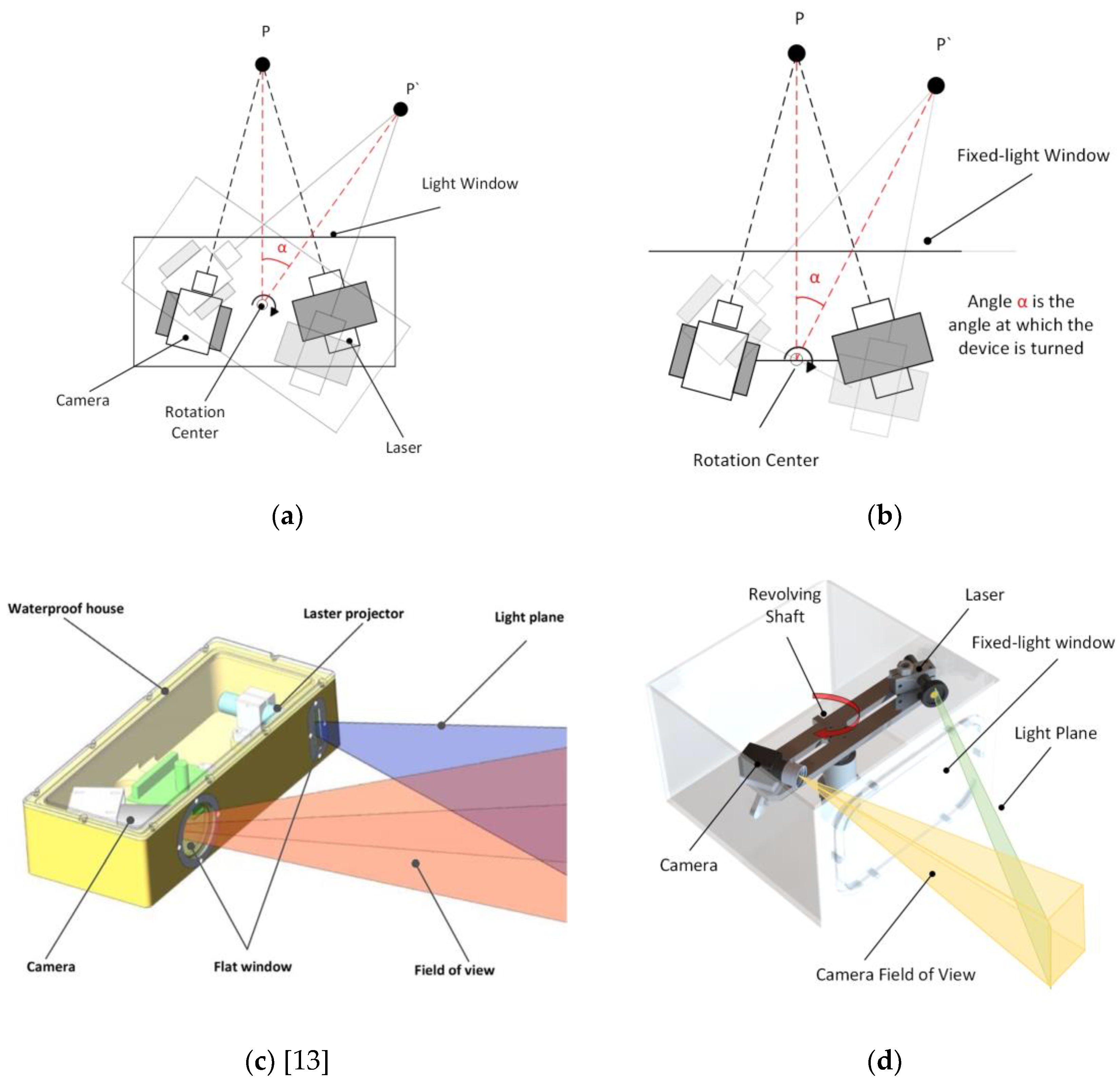
In the context of addressing the issue of refraction error in a system, As seen in
Figure 1’s (a) and (c) [
13] schematics, it is common practice in underwater 3D reconstruction to establish a fixed relationship between the light window, laser scanning imaging system, and rotary table. By maintaining a fixed configuration between these components, the system’s refraction error can be analyzed in a more stable manner. Consequently, this enables the development of a static compensation algorithm for analyzing the refraction process and effectively mitigating the effects of refraction on the laser scanning imaging system. The utilization of this technology allows for enhanced visibility of the refraction error process. However, the analysis process lacks specificity and does not thoroughly account for the mechanical parameters of the imaging system [
14]. In addition, certain individuals further elaborate on the stable refraction process by conducting a comprehensive analysis of the two refraction processes involving three media. They also incorporate system mechanical parameters, such as the distance between the optical center and the window plane, to enhance the effectiveness and credibility of the established refraction compensation model [
15]. However, it is worth noting that the calibration method for determining the distance between the optical center and the window plane often heavily relies on the aforementioned compensation model. The complexity of the problem-solving process is noteworthy. In addition to doing an analysis of the refraction process in order to mitigate the inaccuracy, Miguel Castillo A novel three-dimensional laser sensor was presented by Miguel Castillon et al. [
16], wherein the inherent properties of a two-axis mirror are utilized to transform the projected curve into a straight line upon refraction in water. This strategy effectively mitigates the occurrence of refraction errors. The refraction compensation algorithm employed in the FWLS scanning imaging system, as investigated in this study, bears resemblance to the refraction compensation method utilized in the galvanometer-fixed light window imaging system [
17,
18]. However, it is worth noting that the refraction compensation algorithm in the latter system typically only takes into account the pixel coordinate shift in the return light. As seen in
Figure 1’s (b) and (d) schematics, this study presents the development of a model that simulates the dynamic process of a FWLS scanning imaging system based on the imaging principle. The refraction compensation algorithm for the FWLS scanning imaging system is developed by solving the equations for the laser plane and the dynamic pixel coordinate offsets associated with dynamic refraction.
In their study, Palomer et al. integrated a mechanical arm with a 3D scanner and investigated a calibration technique to establish the spatial relationship between the underwater scanner and the mechanical arm [
19]. This enabled the successful manipulation of objects located at the bottom of a water tank. A laser scanning system operating at a wavelength of 525 nm has been created by Michael Bleier from Julius Maximilians University in Germany. This system enables the static and dynamic scanning of objects within a water tank. Based on the acquired point cloud data, it is evident that the reconstruction error of the two-state systems is below 5 cm. Hildebrandt et al. [
20]. implemented a servo motor with a rotation range of 45° to position the laser line, achieving an accuracy of around 0.15. The camera’s sensor is 640 x 480 CMOS, capable of capturing and scanning images at a rate of 200 frames per second. The imaging system has the capability to retrieve 300,000 data points within a time frame of 2.4 seconds, enabling it to acquire a substantial amount of information regarding the surface of the item. In the pursuit of investigating an algorithm for compensating underwater refraction errors, one approach is to make modifications to the existing method in order to minimize the errors [
21]. Alternatively, a novel correction algorithm can be developed with the specific objective of addressing refraction-related distortions [
22]. Hao [
23] and Xue developed a refraction error correction algorithm based on their system’s refraction model. This technique effectively enhances the three-dimensional image accuracy of the system to approximately 0.6 mm. In their study, Ou et al. employed a combination of binocular cameras and laser fusion technology to develop a model of the system. They conducted an analysis of the refraction error, performed system calibration, and ultimately achieved high-precision imaging in low-light underwater conditions.
This paper studies an underwater self-rotating line laser scanning 3D reconstruction system to enable the high-precision 3D reconstruction of underwater targets. The second section introduces the coordinate transformation and parameter calibration needed for 3D reconstruction. The building of the point cloud and the extraction of the light stripe center are covered in the third section. A refractive error compensation algorithm for the system’s underwater refractive error is presented in the fourth section. The standard sphere is utilized as the measured target in the fifth part, where refraction error analysis is conducted both before and after correction. Here are the specifics [
24].
2. Description of the underwater imaging device
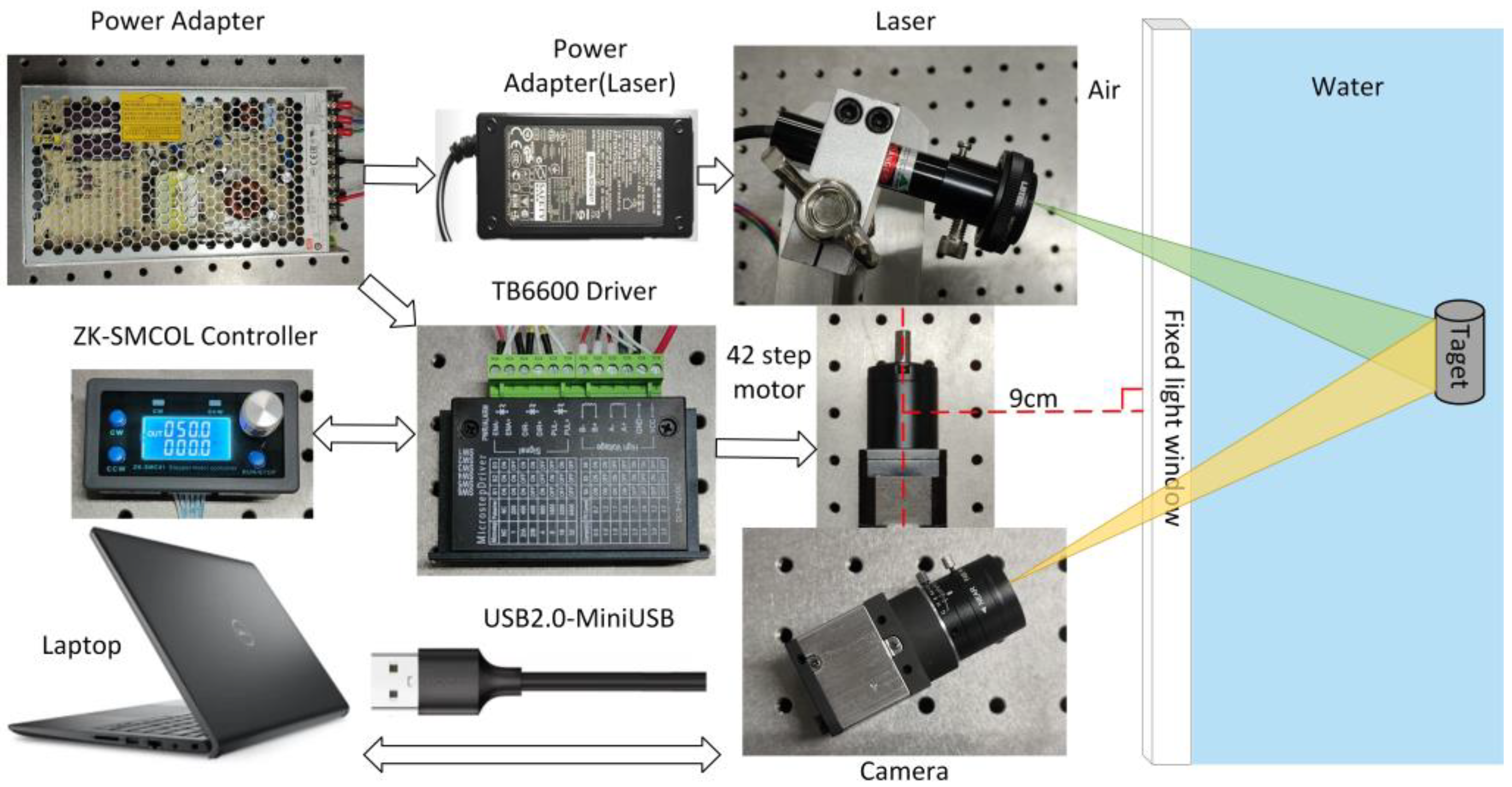
As depicted in
Figure 2, the hardware component of the underwater imaging equipment comprises a CCD camera, a line laser, a rotating table, a controller and a driver. The camera utilized in this study is Thorlabs’ DCU224C industrial camera, which offers a resolution of 1280 × 1024 pixels. It operates within a spectral range of 350 nm to 600 nm. The camera is equipped with an 8-mm focal length lens, specifically the MVCAM-LC0820-5M model, providing a field-of-view angle of 46.8° horizontally, 36° vertically, and 56° diagonally. For the line laser, a 530 nm line laser with a power output of 200mW is selected. The rotary table employed in this setup consists of a 42-stepping motor, along with its corresponding controller and driver.
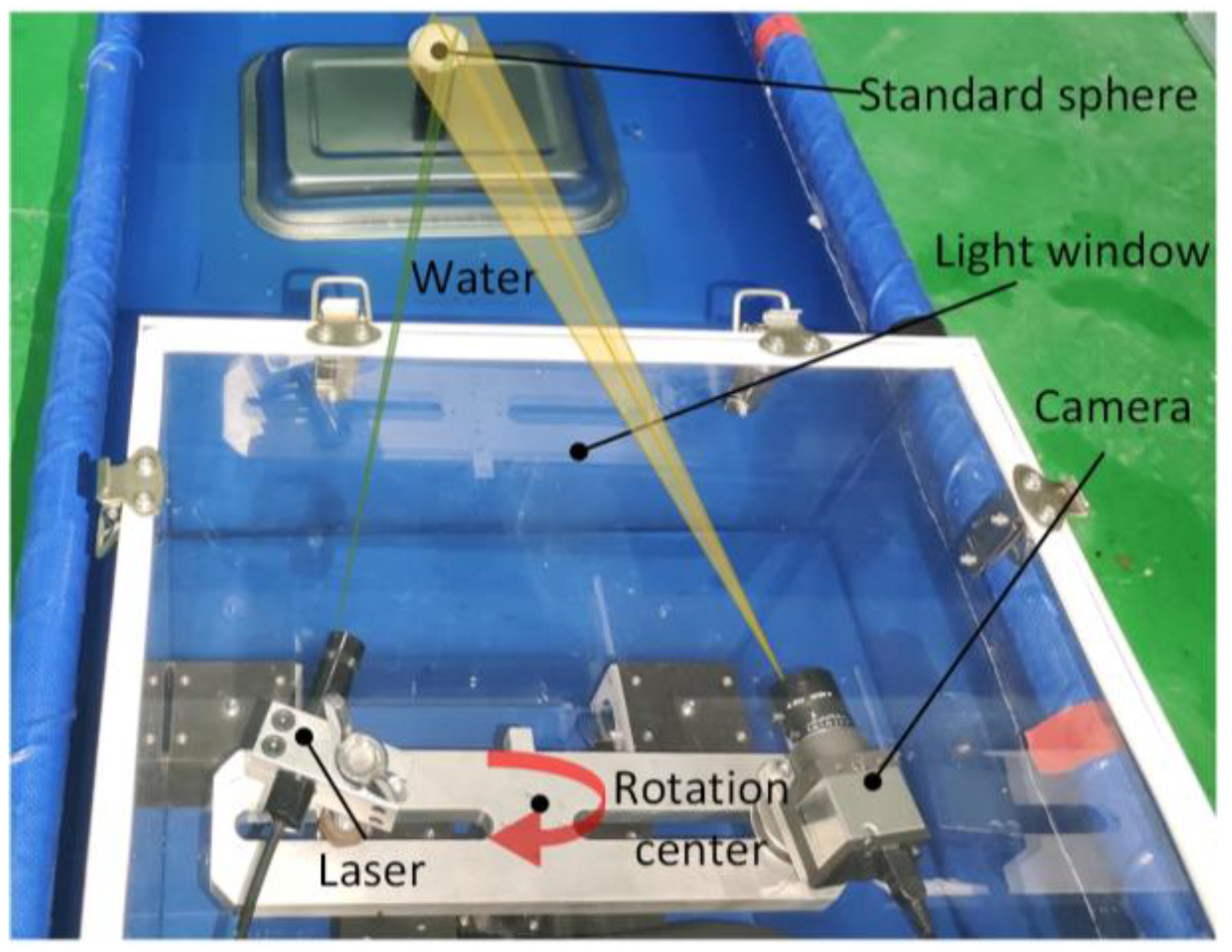
As seen in
Figure 3, the camera and laser are affixed to opposite ends of the rotary table beam, with their relative locations remaining constant. The motor rotation axis is positioned at a vertical distance of 9cm from the light window. By manipulating the motor rotation speed and direction at the controller end, the beam may be rotated. This allows for horizontal scanning of the system at a fixed point within a 360° range. The entire apparatus is enclosed behind a waterproof cover made of ultra-white clear glass, with dimensions of 30×30×40cm and a wall thickness of 5mm.
2.1. The calibration of light planes and rotation axes
2.1.1. Light Plane Fitting Utilizing the Least Square Method
The CCD internal and external reference matrix, as well as the transformation matrix between the camera coordinate system and the tessellated coordinate system [
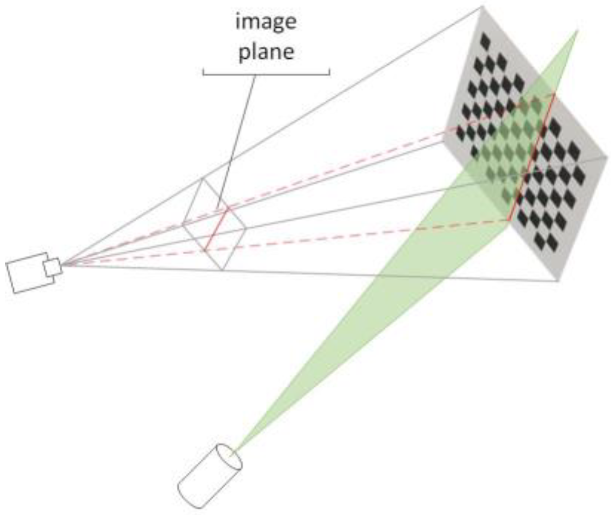
25], can be readily derived using the Zhang calibration method. As seen in
Figure 4, if
is the light plane equation, then finding the coefficients of this plane equation only requires four locations. Using the checkerboard calibration method, first create two sets of checkerboard calibration images, one with and one without light strips. Next, use the light strip extraction method in Section 3.1 to extract the actual coordinates of the light strips on the target. Finally, use the conversion matrix to convert the coordinates to the camera coordinate system. From the two sets of images, two linear equations can be extracted, and the light plane equation can be found using least squares fitting [
26,
27].
Error equation from plane equation:
By streamlining the error equation’s partial derivation, we can obtain:
Since the system of equations is linear, Clem’s approach can be used to solve it and obtain the final coefficients of the plane equation as:
In conclusion, the equation for the light plane derived from the experimental calibration is:
2.1.2. The calibration of rotary axis
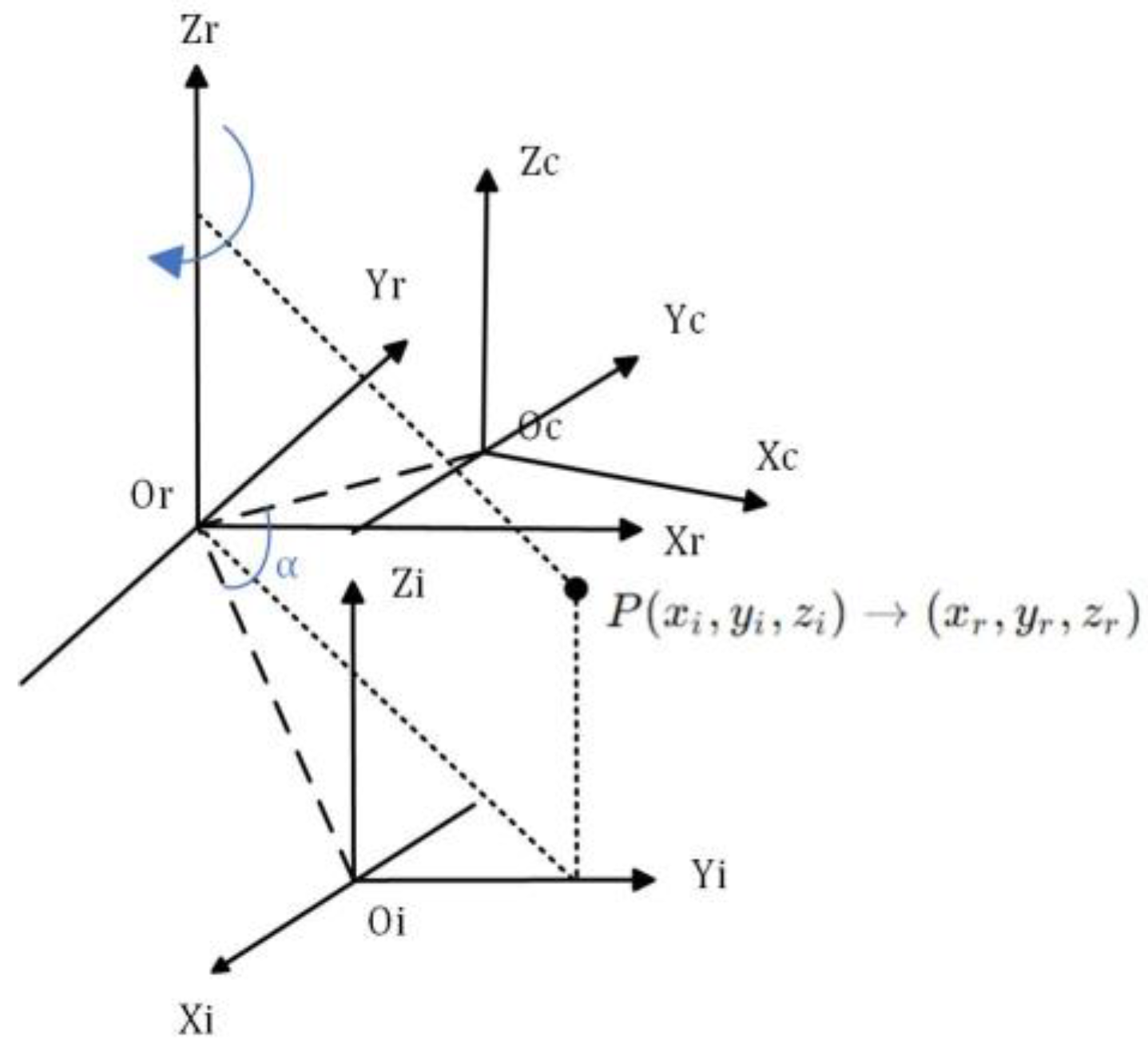
In the context of rotary scanning measurement, if the rotation angle is known (which is determined by the motor controller), it is possible to obtain the point cloud data of the entire object surface by performing a coordinate solution using the camera external reference matrix and the laser plane equation, provided that the linear equation of the rotation axis is obtained [
28]. As depicted in the theoretical model of the imaging device illustrated in
Figure 5, it is observed that the
Zr axis aligns with the rotational axis of the system. The coordinate system for the rotation axis is denoted as
.The camera coordinate system at the initial scanning location of the device is denoted as
, while the CCD optical center is represented as
Oc. After rotating clockwise by an angle of α around the rotation axis
Zr, the camera coordinate system is denoted as
.
As depicted in
Figure 6, the schematic figure illustrates the process of rotary axis calibration. It is imperative that during the rotation and scanning of the device, each point on the target’s trajectory must be on a circle centered on the axis of rotation. As a result, the checkerboard grid’s corner points that rotate at a specific angle are first calibrated using the Zhang method. The corner points’ coordinates are then converted to the camera coordinate system, and they are subsequently fitted to a circle. Subsequently, the property that the angle points of various heights on the chessboard target are placed at different places on the rotation axis is used to generate a series of coordinates of the center of a circle. Finally, the circle’s centers’ coordinates are fitted to a straight line, allowing the equation of the straight line for the rotary axis in the camera coordinate system to be obtained as
[
29,
30,
31].
The conversion of pixel coordinates to the rotary axis coordinate system is performed in the following manner.:
where A is the internal reference matrix of the camera and R,T are the rotation and translation matrices from the pixel coordinate system to the rotational coordinate system, getting the matrix A is simple as:
In conclusion, the equation for the plane of the rotary axis derived from the experimental calibration is:
The CCD optical center exhibits circular motion with the rotating shaft as its center. According to the aforementioned calibration, the vertical distance between the CCD optical center coordinate and the rotating shaft is determined to be R = 109.7855mm. The measured distance between the center of the rotating axis and the center of the camera is approximately 110mm, which closely aligns with the calibration findings of the rotary axis in determining the value of r. The credibility of the calibration data pertaining to the rotational axis is evident.
3. Laser strip center extraction and point cloud construction
Rapid and precise extraction of the laser stripe centerline of the measured object surface is required to achieve the high precision of the laser scanning reconstruction system, as the laser stripe reflects target surface shape information.
The flowchart of the light bar center extraction algorithm used in this paper is shown in
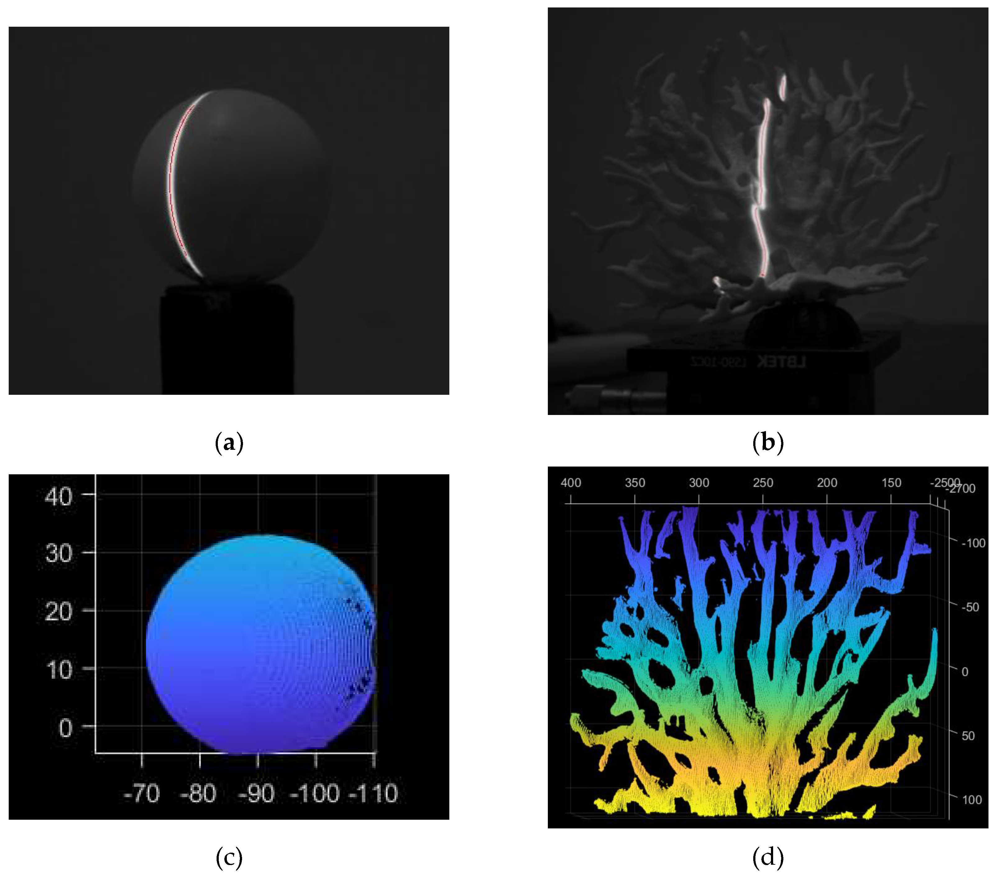
Figure 7. In order to obtain a smoother denoised image, we first apply Gaussian filter denoising, which involves summing up all of the image’s pixel values and dividing each value by itself as well as by the values of the other pixels in the area around the weighted average of the value. Next, the IterationBw algorithm updates the adaptive threshold for light stripe extraction, and the Steger algorithm extracts the light stripe’s center point [
32,
33,
34]. This method makes it possible to rapidly and accurately acquire the light bar center coordinates of the scanning data.
Figure 8(
a) and 8(
b) illustrate the extraction impact during the actual measurement.
In Equation (9),
Zc signifies the Z-coordinate of the observed point on the camera’s optical axis, i.e., the object’s depth or distance in the camera’s coordinate system.
dx, dy are the unit pixel’s physical dimensions in the X and Y axes;
fx, fy are the camera’s focal point coordinates; and R,T are the translation and rotation matrices from the camera coordinate system to the world coordinate system. After obtaining the two-dimensional pixel coordinates of the center of the light plane, the laser plane and coordinate system transformation connection found in
Section 2.1.1 and
Section 2.1.2 can be combined to acquire the point cloud data of the observed target, as indicated in Formula (9). The system’s motion parameters (motor speed) are then inserted, and the 3D point cloud data is stitched to produce the 3D point cloud model of the observed target, as shown in
Figure 8(c) and
Figure 8(d).
4. Refractive error compensation in underwater light windows
In the context of underwater measurements, the FWLS scanning imaging device is enclosed within a waterproof cover to ensure its functionality. Consequently, the device and the object being measured are situated in distinct media. When the instrument is operational, the laser will be emitted towards the object being measured by passing through the light window and water. The light that is reflected back from the object will likewise pass through the light window and water and be subsequently detected by the CCD. Hence, it becomes apparent that the laser plane and the CCD image coordinate experience an excursion due to refraction [
35,
36,
37]. To address this issue, mathematical models are established based on the measurement process, allowing for the determination of equations describing the dynamic laser plane refraction and the offset of pixel coordinates on the plane [
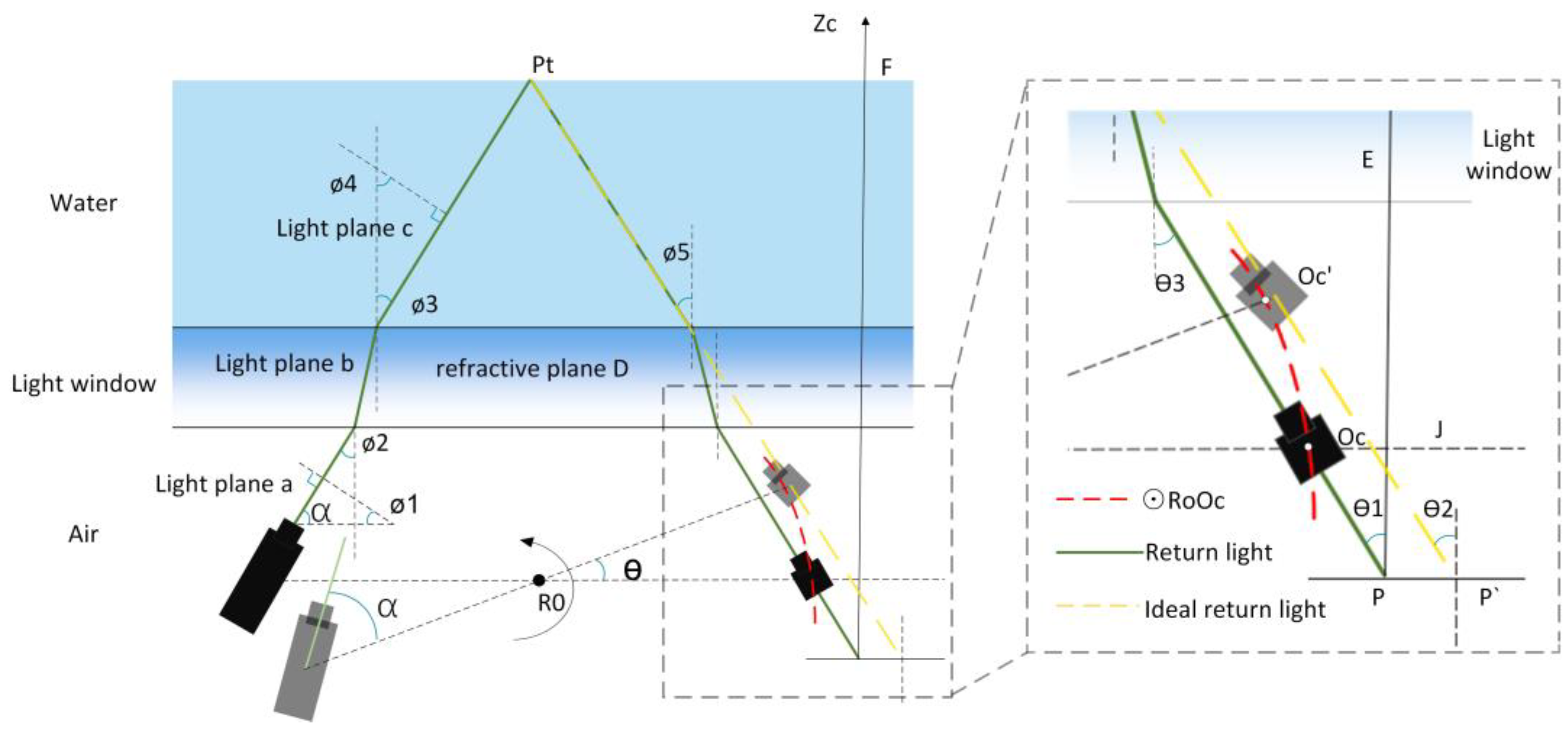
38]. This mathematical model is illustrated in
Figure 9.
As indicated in
Figure 9, where Ro is the rotating axis’s center, angle
represents the inclination between the normal vector of the light plane a and the horizontal direction, while angle
denotes the inclination between the light plane c and the vertical direction.
denotes the angle at which the laser light enters the light window, while
represents the angle at which the laser light exits the light window and enters the water. Similarly,
signifies the angle at which the return light enters the light window from the water, and
denotes the angle at which the return light exits the light window and enters the air. P’ is the coordinate point on the image plane of the theoretical return light of the measured target point Pt, and position P is the coordinate point on the image plane of the actual return light of the measured target point Pt. The angle formed by the laser and the rotating table’s beam is α. When the device is in its original position, the CCD is at position
Oc, and it rotates counterclockwise for t seconds to reach position
Oc’, with a rotation angle of
. The simple geometric connection can be used to calculate the relationship between
and the angle of rotation at moment t:
The variable can be mathematically represented as , where N is the number of frames associated with the image, T represents the camera frame rate, and ω signifies the minimum rotation unit speed of the device.
4.1. Resolving the light plane’s dynamic refraction equation
Let us consider a refracting plane with a normal vector D(0,0,1). The incident light plane, with a normal vector
(a, b, c) denoted as (a), is refracted through the glass and forms a new light plane, denoted as (b), with a normal vector (
,
,
). Subsequently, the light plane b enters the water through the glass and is refracted again, resulting in a new light plane denoted as (c), with a normal vector (
,
,
). The refractive index ratio between air and water is denoted as
. By Snell’s law:
Normalize the light plane c’s normal vector:
Putting this into equation (12) results in:
We know that since the normal of the light plane (a), the refraction plane (D), and the refracted light plane (c) are coplanar:
Equation (14)(15) provides us with:
If we substitute the intersection point of the light plane (c) with the light window
into the equation for the light plane (c),where H is the distance from the CCD optical center to the light window, we get:
In conclusion, only the distance between the CCD optical center and the glass is unknown. The CCD optical center rotates in a circular motion with Ro serving as the center and R as the radius from the
Oc position to the
Oc’ position, as seen in
Figure 9’s right panel. The equation for the circle with center
Ro and radius
r, denoted as ⊙
RoOc, can be derived as
. When the device is mounted, the distance from the spinning shaft’s center to the light window-water side is 90 mm, and the equation of the line of refraction D is
z = 90,.It is easy to obtain
. Next, by utilizing Equation 6, the H expression may be converted to align with the camera coordinate system. Consequently, the plane equation of the refracted laser plane (c) can be derived by employing the coupling equation (16)(17).
4.1. Solution for the pixel coordinate offset coefficient
The schematic picture 9 illustrates the mapping of the underwater target point Pt onto the image plane, resulting in the imaging point
P (u, v). If the return light is not subject to refraction by the water body and the light window, it will be observed directly at the location of
. By determining the offset coefficient η between the two points, it is possible to achieve refraction correction for each measured point [
39,
40,
41,
42]. The offset η, which represents the difference between the point
on the image plane corresponding to the theoretical return light and the point
P on the image plane corresponding to the actual return light, can be mathematically described as the ratio of the tangent of
to
, as seen in
Figure 9.
also known as:
Where: f is the camera’s focal length. By Snell’s law:
Then bring equation (10) into (18)to get:
that is:
5. Error analysis experiments
To evaluate the precision of the system, we conducted multiple scans and reconstructions of a standard ball with a radius of 20 mm. This was done within a range of 30 cm to 80 cm, with D representing the working distance. Additionally, we selected six positions within the imaging field of view at different distances. The objective was to calculate the measurement radius of the standard ball before and after correcting for refraction errors. The radius of the standard sphere measurement underwater, without the use of the refraction compensation method, is represented by the symbol R. Conversely, the radius of the measurement after accounting for the correction of refraction errors is marked by Rw. The radius of the standard ball can be determined through a computation, and the measured radius of the standard ball is presented in the table provided.
As seen in
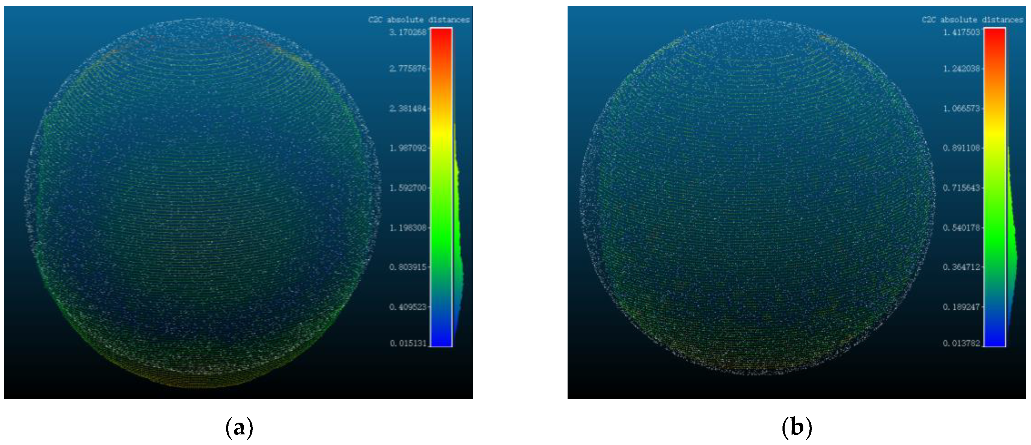
Table 1, in the absence of the refraction error compensation method, the measurement error of the standard ball remains within a range of 2.5mm. The largest measurement error observed is 2.36mm, while the minimum measurement error is -0.67mm. Upon the implementation of the refraction error compensation algorithm, the reconstructed standard ball radius exhibits a minimum error of 0.18mm and a maximum error of 0.9mm. It is apparent from this observation that the addition of the refraction error correction method improved the system’s reconstruction accuracy to some extent. Subsequently, the point cloud data obtained before and following the application of refraction adjustment were chosen for comparison with the point cloud data of the standard ball, which has a radius of 20mm. The distances between the point clouds are illustrated in
Figure 10(a) and
Figure 10(b).
The measured point cloud with the addition of the refraction compensation method clearly matches the actual standard sphere model better, as shown in
Figure 10(a) and
Figure 10(b), and the overall curvature and other details are enhanced.
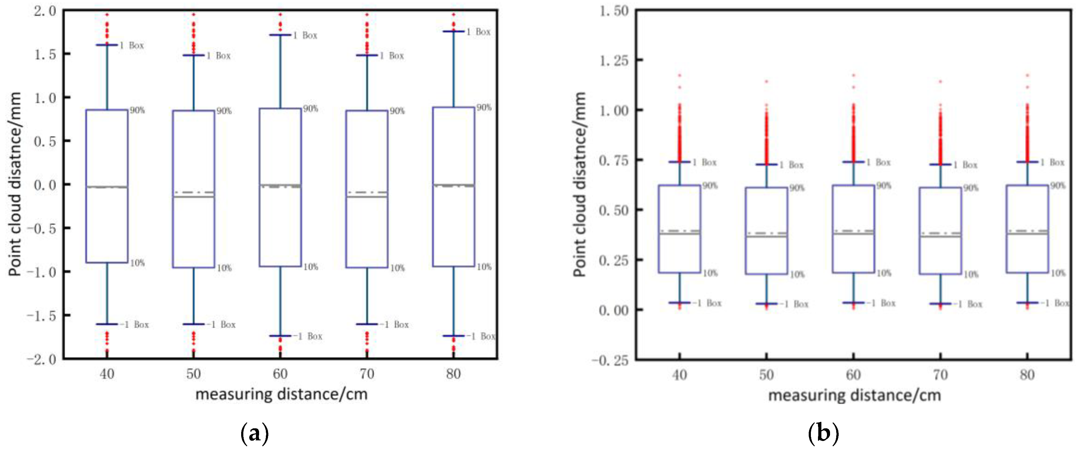
Five sets of point clouds were chosen, both before and after compensation. These point clouds were registered with the standard sphere point cloud, and the distances between the five groups of point clouds and the standard sphere point cloud were obtained. The box plots regarding distance distribution are presented in
Figure 11 (a) and
Figure 11 (b). The box plots diagrams reveal that the disparity between the measured point cloud and the standard sphere is primarily concentrated within the range of (-1, +1) prior to compensation. However, after compensation, the disparity is predominantly distributed within the range of (0.25, 0.75). This observation substantiates the authenticity and efficacy of the compensation algorithm.
6. Conclusions
This study presents a comprehensive description of an advanced underwater fixed light window and laser spinning scanning 3D imaging system. The system is designed to achieve enhanced accuracy in acquiring 3D point cloud data of underwater targets. It accomplishes this through the use of a green line laser, a CCD camera, a rotary table, and a drive unit. The study employs a meticulous calibration process for the light plane and rotary axis to guarantee the precision and correctness of the collected data. The extraction of point cloud data involves the utilization of the Steger method, which is complemented by Gaussian filtering and iterative binarization techniques. This combination is employed to achieve a superior level of accuracy and precision in the extraction light stripe center data process. Furthermore, the research presented a novel technique for compensating refraction errors caused by the dynamic refraction process induced by the laser passes through different media in the fixed light window and laser spinning scanning 3D imaging system. Experimental evidence substantiated the efficacy of this algorithm in enhancing the accuracy of the collected data. The experiments involved conducting an error analysis utilizing a standard sphere. The findings indicated that the reconstruction error ranged from 2.5 mm when the refraction error compensation was not applied. However, after implementing the compensation algorithm, the error reduced to less than 1 mm, resulting in the attainment of highly precise point cloud data. Furthermore, it can be observed that the point cloud model exhibits a closer resemblance to the actual object model following the implementation of refraction compensation. This serves as empirical evidence supporting the efficacy of the compensation method. To a certain degree, it partially compensates for the limited study on the compensation algorithm employed in this particular dynamic refraction process. In summary, this work presents an underwater imaging system that exhibits a broad spectrum of engineering applications. The system demonstrates exceptional precision, rapid data collecting, and superior data quality within a certain measurement range. The implementation of refraction error compensation in this study leads to improved accuracy in the capture of point cloud data. This finding holds significant reference value for both underwater scientific research and engineering applications.
Author Contributions
Conceptualization, JH.Z, T.Z, J.Z and YH.W; Methodology, JH.Z ,T.Z and YH.W; Software, JH.Z and K.Y; Validation, JH.Z, YH.W and XY.W; Formal analysis, JH.Z, K.Y and T.Z; Writing—original draft preparation, JH.Z; Writing—review and editing, JH.Z, T.Z, YH.W and J.Z; Project administration, JH.Z; Funding acquisition, JH.Z, YH.W, T.Z; All authors modified and approved the final submitted materials. All authors have read and agreed to the published version of the manuscript.
Funding
This research was funded by Key research and development project in Heilongjiang Province, China (GZ20220105,GZ20220114); Postdoctoral Science Foundation of China (2023M730533); Fundamental Research Funds for the Central Universities(2572023CT14-05,2572022BF03).
Institutional Review Board Statement
Not applicable.
Informed Consent Statement
Not applicable.
Acknowledgments
The authors are very grateful to the editor and reviewers for their valuable comments on this paper.
Conflicts of Interest
The authors declare no conflict of interest.
References
- Bianco, G.; Gallo, A.; Bruno, F.; Muzzupappa, M. A Comparative Analysis between Active and Passive Techniques for Underwater 3D Reconstruction of Close-Range Objects. Sensors 2013, 13, 11007–11031. [Google Scholar] [CrossRef] [PubMed]
- Massot-Campos, M.; Oliver-Codina, G. Optical Sensors and Methods for Underwater 3D Reconstruction. Sensors 2015, 15, 31525–31557. [Google Scholar] [CrossRef] [PubMed]
- Malamas, E.N.; Petrakis, E.G.M.; Zervakis, M.; Petit, L.; Legat, J.D. A survey on industrial vision systems, applications and tools. Image Vis. Comput. 2003, 21, 171–188. [Google Scholar] [CrossRef]
- Nakatani, T.; Li, S.; Ura, T.; Bodenmann, A.; Sakamaki, T. 3D visual modeling of hydrothermal chimneys using a rotary laser scanning system. In Proceedings of the 2011 IEEE Symposium on Underwater Technology and Workshop on Scientific Use of Submarine Cables and Related Technologies; 2011; 1-5. [Google Scholar]
- Shen, Y.; Zhao, C.; Liu, Y.; Wang, S.; Huang, F. Underwater optical imaging: Key technologies and applications review. IEEE Access 2021, 9, 85500–85514. [Google Scholar] [CrossRef]
- Valkenburg, R.J.; McIvor, A.M. Accurate 3D measurement using a structured light system. Image Vis. Comput. 1998, 16, 99–110. [Google Scholar] [CrossRef]
- Geng, J. Structured-light 3D surface imaging: a tutorial. Advances in optics and photonics 2011, 3, 128–160. [Google Scholar] [CrossRef]
- Liu, J.; Wang, Y. 3D surface reconstruction of small height object based on thin structured light scanning. Micron 2021, 143, 103022. [Google Scholar] [CrossRef] [PubMed]
- Chen, C.; Kak, A. Modeling and calibration of a structured light scanner for 3-D robot vision. In Proceedings of the Proceedings. 1987 IEEE International Conference on Robotics and Automation; 1987; 807-815. [Google Scholar]
- Zhang, Z. A flexible new technique for camera calibration. IEEE Transactions on pattern analysis and machine intelligence 2000, 22, 1330–1334. [Google Scholar] [CrossRef]
- Dewar, R. Self-generated targets for spatial calibration of structured-light optical sectioning sensors with respect to an external coordinate system; Society of Manufacturing Engineers: 1988.
- Huynh, D.Q.; Owens, R.A.; Hartmann, P. Calibrating a structured light stripe system: a novel approach. International Journal of computer vision 1999, 33, 73–86. [Google Scholar] [CrossRef]
- Fan, H.; Qi, L.; Ju, Y.K.; Dong, J.Y.; Yu, H. Refractive laser triangulation and photometric stereo in underwater environment. Opt. Eng. 2017, 56, 10. [Google Scholar] [CrossRef]
- Xue, Q.; Sun, Q.; Wang, F.; Bai, H.; Yang, B.; Li, Q. Underwater high-precision 3D reconstruction system based on rotating scanning. Sensors 2021, 21, 1402. [Google Scholar] [CrossRef] [PubMed]
- Zhao, J.; Cheng, Y.; Cai, G.; Feng, C.; Xu, B. Correction model of linear structured light sensor in underwater environment. Optics and Lasers in Engineering 2022, 153, 107013. [Google Scholar] [CrossRef]
- Castillón, M.; Forest, J.; Ridao, P. Underwater 3D scanner to counteract refraction: Calibration and experimental results. IEEE/ASME Transactions on Mechatronics 2022, 27, 4974–4982. [Google Scholar] [CrossRef]
- Chi, S.; Xie, Z.; Chen, W. A laser line auto-scanning system for underwater 3D reconstruction. Sensors 2016, 16, 1534. [Google Scholar] [CrossRef] [PubMed]
- Xie, Z.; Li, X.; Xin, S.; Xu, S. Underwater Line Structured-Light Self-Scan Three-Dimension Measuring Technology. Chinese Journal of Lasers 2010, 37, 2010–2014. [Google Scholar]
- Palomer, A.; Ridao, P.; Youakim, D.; Ribas, D.; Forest, J.; Petillot, Y. 3D laser scanner for underwater manipulation. Sensors 2018, 18, 1086. [Google Scholar] [CrossRef] [PubMed]
- Hildebrandt, M.; Kerdels, J.; Albiez, J.; Kirchner, F. A practical underwater 3D-Laserscanner. In Proceedings of the OCEANS 2008; 2008; 1-5. [Google Scholar]
- Kwon, Y.-H.; Lindley, S.L. Applicability of four localized-calibration methods in underwater motion analysis. In Proceedings of the ISBS-Conference Proceedings Archive; 2000. [Google Scholar]
- Kwon, Y.-H. Object plane deformation due to refraction in two-dimensional underwater motion analysis. Journal of Applied Biomechanics 1999, 15, 396–403. [Google Scholar] [CrossRef]
- Fan, H.; Qi, L.; Ju, Y.; Dong, J.; Yu, H. Refractive laser triangulation and photometric stereo in underwater environment. Opt. Eng. 2017, 56, 113101–113101. [Google Scholar] [CrossRef]
- Ou, Y.; Fan, J.; Zhou, C.; Tian, S.; Cheng, L.; Tan, M. Binocular Structured Light 3-D Reconstruction System for Low-Light Underwater Environments: Design, Modeling, and Laser-Based Calibration. IEEE Transactions on Instrumentation and Measurement 2023, 72, 1–14. [Google Scholar] [CrossRef]
- Zhang, Z. Camera calibration with one-dimensional objects. IEEE transactions on pattern analysis and machine intelligence 2004, 26, 892–899. [Google Scholar] [CrossRef] [PubMed]
- Muralikrishnan, B.; Raja, J. Least-squares best-fit line and plane. Computational Surface and Roundness Metrology 2009, 121–130. [Google Scholar]
- Yang, Y.; Zheng, B.; Zheng, H.-y.; Wang, Z.-t.; Wu, G.-s.; Wang, J.-c. 3D reconstruction for underwater laser line scanning. In Proceedings of the 2013 MTS/IEEE OCEANS-Bergen; 2013; 1-3. [Google Scholar]
- Lee, J.; Shin, H.; Lee, S. Development of a wide area 3D scanning system with a rotating line laser. Sensors 2021, 21, 3885. [Google Scholar] [CrossRef] [PubMed]
- Zhu, Z.; Yang, J.; Wang, X.; Qi, G.; Wu, C.; Fan, H.; Qi, L.; Dong, J. Rotation Axis Calibration of Laser Line Rotating-Scan System for 3D Reconstruction. In Proceedings of the 2020 11th International Conference on Awareness Science and Technology (iCAST); 2020; 1-5. [Google Scholar]
- Liu, T.; Wang, N.; Fu, Q.; Zhang, Y.; Wang, M. Research on 3D reconstruction method based on laser rotation scanning. In Proceedings of the 2019 IEEE international conference on mechatronics and automation (ICMA); 2019; 1600-1604. [Google Scholar]
- Wu, Q.; Li, J.; Su, X.; Hui, B. An approach for calibrating rotor position of three dimensional measurement system for line structured light. Chinese Journal of Lasers 2008, 35, 1224–1227. [Google Scholar]
- Yang, H.; Wang, Z.; Yu, W.; Zhang, P. Center Extraction Algorithm of Linear Structured Light Stripe Based on Improved Gray Barycenter Method. In Proceedings of the 2021 33rd Chinese Control and Decision Conference (CCDC); 2021; 1783-1788. [Google Scholar]
- Li, W.; Peng, G.; Gao, X.; Ding, C. Fast Extraction Algorithm for Line Laser Strip Centers. Chinese Journal of Lasers 2020, 47. [Google Scholar]
- Ma, X.; Zhang, Z.; Hao, C.; Meng, F.; Zhou, W.; Zhu, L. An improved method of light stripe extraction. In Proceedings of the Aopc 2019: Optical Sensing and Imaging Technology; 2019; 925-928. [Google Scholar]
- Chadebecq, F.; Vasconcelos, F.; Lacher, R.; Maneas, E.; Desjardins, A.; Ourselin, S.; Vercauteren, T.; Stoyanov, D. Refractive Two-View Reconstruction for Underwater 3D Vision. International Journal of Computer Vision 2020, 128, 1101–1117. [Google Scholar] [CrossRef] [PubMed]
- Sun, Q.; Xue, Q.; Zhang, D.; Bai, H. Research on the 3D laser reconstruction method of underwater targets. Infrared and Laser engineering 2022, 51. [Google Scholar]
- Gu, C.J.; Cong, Y.; Sun, G.; Gao, Y.J.; Tang, X.; Zhang, T.; Fan, B.J. MedUCC: Medium-Driven Underwater Camera Calibration for Refractive 3-D Reconstruction. IEEE Trans. Syst. Man Cybern. -Syst. 2022, 52, 5937–5948. [Google Scholar] [CrossRef]
- Castillón, M.; Palomer, A.; Forest, J.; Ridao, P. State of the art of underwater active optical 3D scanners. Sensors 2019, 19, 5161. [Google Scholar] [CrossRef] [PubMed]
- Lyu, N.; Yu, H.; Han, J.; Zheng, D. Structured light-based underwater 3-D reconstruction techniques: A comparative study. Optics and Lasers in Engineering 2023, 161, 107344. [Google Scholar] [CrossRef]
- Li, S.; Gao, X.; Wang, H.; Xie, Z. Monocular underwater measurement of structured light by scanning with vibrating mirrors. Optics and Lasers in Engineering 2023, 169, 107738. [Google Scholar] [CrossRef]
- Castillón, M.; Palomer, A.; Forest, J.; Ridao, P. Underwater 3D scanner model using a biaxial MEMS mirror. IEEE Access 2021, 9, 50231–50243. [Google Scholar] [CrossRef]
- Chantler, M.J.; Clark, J.; Umasuthan, M. Calibration and operation of an underwater laser triangulation sensor: the varying baseline problem. Opt. Eng. 1997, 36, 2604–2611. [Google Scholar] [CrossRef]
|
Disclaimer/Publisher’s Note: The statements, opinions and data contained in all publications are solely those of the individual author(s) and contributor(s) and not of MDPI and/or the editor(s). MDPI and/or the editor(s) disclaim responsibility for any injury to people or property resulting from any ideas, methods, instructions or products referred to in the content. |
© 2023 by the authors. Licensee MDPI, Basel, Switzerland. This article is an open access article distributed under the terms and conditions of the Creative Commons Attribution (CC BY) license (http://creativecommons.org/licenses/by/4.0/).
