Preprint
Article

Multi-Material Additive Manufacturing of PLLA-HA/GO Scaffold Fabricated via DLP for Bone Loss: Experimental Investigation, Numerical Analysis, and Cell Study

Altmetrics

Downloads

156

Views

121

Comments

0

Submitted:

11 November 2023

Posted:

14 November 2023

You are already at the latest version

Alerts
Abstract
In this study, an optimized multi-material system was designed and developed to print samples in various applications, including biomedical fields (e.g., mandibular bone loss). To improve the mechanical and biological properties of scaffolds utilized for dental bone loss applications, a multi-material setup was devised, which employs digital light processing technology. This setup consists of a linear system comprising two resin vats and one ultrasonic cleaning tank, enabling the integration of diverse materials and structures to optimize the composition of the scaffold. This approach was used to print multi-material PLLA scaffolds containing 20 wt.%. HA on the interior side, and PLLA containing 1 wt.% GO on the exterior surface of the scaffold, which were evaluated mechanically and biologically after printing. The scaffold was designed using a triply periodic minimal surface (TPMS) lattice structure, which is known to possess favorable mechanical and biological properties. Various multi-material samples were successfully printed and evaluated to illustrate the multiple-material setup's potential for ensuring proper function, cleaning, and adequate interface bonding. By numerically evaluating several TMPS structures, a novel Gyroid TPMS scaffold with a nominal porosity of 50% was developed and validated experimentally. The biological properties of the scaffolds were also evaluated, including surface morphology, (3-(4,5-dimethylthiazol-2-yl)-2,5-diphenyltetrazolium bromide) MTT assay, and cell adhesion. Based on the results, multi-material components with the least contaminations with suitable mechanical and biological properties were successfully printed. By combining PLLA-HA and PLLA-GO, this innovative technique holds tremendous potential for enhancing the effectiveness of regenerative procedures in the field of dentistry.
Keywords: 
Subject: Engineering  -   Mechanical Engineering

1. Introduction

In recent decades, tissue-engineered bone substitutes have emerged as a viable alternative to autografts and allografts. This is largely due to the limited availability of bone grafts, which may also induce infection at the donor site. In tissue engineering, biomaterial scaffolds are combined with cells and active molecules to promote tissue regeneration [1,2]. Scaffolds should imitate the function of the extracellular matrix (ECM) to provide a proper substrate for the attachment, proliferation, and differentiation of cells [3,4,5,6].
The suitable scaffolds for bone tissue engineering (BTE) should have the following key factors: (i) biological properties, (ii) material, (iii) structural characteristics, and (iv) manufacturing techniques [9]. Regarding biological properties, BTE scaffolds are expected to be biocompatible, biodegradable, as well as suitable for cell adhesion and proliferation. For many years, metal has been the preferred material for engineered bone tissue because of its strength and durability. However, bone cells exhibit poor adhesion to metals and may experience stress shielding, as well as issues related to non-degradability and biological incompatibility. Consequently, researchers have been exploring alternative materials that can be used for bone tissue engineering. Bio-composite polymers and calcium phosphate-based bioceramics are two promising options that have been biologically compatible, degradable, and effective in promoting bone regeneration. These materials, such as hydroxyapatite and biphasic calcium phosphate, can mimic natural bone chemistry and allow porous scaffolds to replace standard grafting applications [7,8]. This is particularly important for treating bone loss in the mandible, which can lead to functional and aesthetic problems. Biomaterial scaffolds, including hydroxyapatite (HA), biphasic calcium phosphate (BCP), poly lactic-co-glycolic acid (PLGA), and poly-L-lactic acid (PLLA) acid have been studied for their potential to promote bone regeneration in the mandible, have been investigated [9,10,11]. Hydroxyapatite, a mineral found in bone, has demonstrated potential for promoting new bone growth and tissue integration [12]. Incorporating 20% nHA and (reduced graphene oxide) RGO has been found to enhance cell proliferation and the formation of new bone [13]. PLLA has shown promise for bone regeneration and dental applications, particularly in mandibular reconstruction. This is due to its ability to facilitate bone formation and offer mechanical support to the regenerated bone, as a result of its high strength and stiffness [14]. Graphene oxide (GO) has a wide range of potential applications in the biomedical field. Furthermore, GO has been found to enhance cell proliferation, drug loading, and antimicrobial and mechanical properties of composite materials [15,16,17].
It has demonstrated that pore size, porosity, and interconnectivity of the pores play a paramount role in the growth, development, and transport of blood vessels, nutrients, and oxygen as structural properties. Structural properties of scaffolds also affect biological and mechanical properties, in which mechanical properties decrease with increasing porosity [18,19,20,21]. A triply periodic minimal surface (TPMS) lattice offers several advantages over conventional scaffolds due to its unique structure and design flexibility, making it an attractive option for overcoming the challenge of decreased mechanical properties associated with increased porosity. Also, TPMS lattice materials offer significant advantages, including weight reduction, high strength, superior shock resistance, excellent energy absorption, excellent pore connectivity, high surface-to-volume ratio, smooth curvatures and joints and high permeability [32]. In light of these properties, TPMS lattices have found applications in biomedicine [24,25,26], as well as photovoltaic, electrochromic devices, and aerospace [27].
To ensure optimal tissue regeneration, it is crucial to have a scaffold with adequate mechanical support. Numerical analysis software such as ABAQUS can simulate the mechanical behavior of various structures, including triply periodic minimal surface (TPMS) lattice structures used as scaffolds in tissue engineering. By predicting their long-term durability and identifying potential failure mechanisms, this software helps optimize scaffold design, ultimately improving the safety and efficacy of tissue engineering scaffolds [28].
The application of ceramic suspensions in polymerization-based additive manufacturing (AM) techniques, such as stereolithography (SLA) [29] and digital light processing (DLP) [30], has enabled the creation of more intricate pore structures than were previously impossible. This has expanded the design possibilities in manufacturing and overcome the limitations of conventional methods, which were unable to produce such complex and accurate structures. Despite the need for multi-material components that offer a combination of mechanical, electrical, chemical, biological, or optical properties, current stereolithography 3D printers available on the market are incapable of printing them [31].To ensure the quality of the final printed part, minimizing cross-contamination between different materials during 3D printing is essential. Cleaning, therefore, plays a critical role in multi-material 3D printers [32]. Ultrasonic cleaning is an effective method for cleaning multi-material resin 3D printed samples, particularly those with complex geometries or porous structures. The high-frequency sound waves are capable of penetrating small pores and removing any excess resin or uncured material that may be trapped, thus improving the overall quality of the printed part [33,34].
The purpose of this study was to develop an optimized multi-material system to print samples in various applications, including biomedical fields. As a means of demonstrating the system's potential and the quality of the samples' interface, multi-material parts were printed and evaluated. Afterward, the effects of post-cure and heat treatment on the bio-resins were assessed. To achieve a structure with high mechanical strength, an optimized TPMS structure was chosen through finite element modeling to be printed as a multi-material scaffold. As well, in-vitro biocompatibility studies were conducted to evaluate MTT and cell attachments to the novel TPMS scaffold. This study consists of the following major novelties and objectives: An optimized multi-material system has been designed and developed via a DLP 3D printer, the TPMS structure has been selected based on numerical analysis, and a multi-material PLLA-GO/HA scaffold has been printed for hard tissue engineering applications.

2. Materials and Methods

2.1. Material Preparation:

Raw materials: One commercial resin and four dyes (red, blue, green, and orange) were bought from Jamghe (China). Functionalized PLLA was synthesized at the laboratory base on the procedure as stated in Ref. [35]. Accordingly, a colorless viscose polymer was synthesized by adding 0.034 g glycerol to 15 g of 90% L-lactic acid and then subjecting the mixture to a series of reactions involving temperature changes and the addition of zinc acetate dehydrate, resulting in the production of PLLA oligomers. The oligomers were then functionalized by adding methacrylic anhydride to the reaction vessel, which was stirred and refluxed before being purified through liquid-liquid extraction with brine solution and dichloromethane. Materials like L-lactic acid monomers, Methacrylic anhydride, Zinc acetate dihydrate (Zn (CH₃CO₂) ₂·2H₂O), 2-ethyl-2-hydroxymethyl Trimethacrylate (TMPTMA), Diphenyl (2,4,6-trimethyl benzoyl) phosphine oxide (TPO), Penicillin, Streptomycin, Dimethyl sulfoxide (DMSO), and Phosphate buffered saline (PBS) were all purchased from Sigma Aldrich, USA. Sodium chloride 97%, Disodium sulfate (Na2SO4) 99%, Toluene, Ethanol, Dichloromethane, N-methyl pyrrolidone, Triethylamine, Glycerol, and 3-[4,5-dimethylthiazol-2-yl]-2, 5-diphenyltetrazolium bromide (MTT) were prepared from Merck, Germany. Also, components such as Orasol orange dye (Ciba Specialty Chemicals, Switzerland) and hydroxyapatite (HA), and Graphon oxide (GO) nanoparticles were provided by Novateb Pars Co., Iran, and Fetal bovine serum (FBS) was purchased from Gibco, USA. Dulbecco's modified eagle medium (DMEM) was bought from Life Technologies Inc., USA, and mouse fibroblast cells (HFS-1) were purchased from the Pasture Institute of Iran.
Resin formulation: Initially, 20 wt.% TMPTMA as a crosslinker, 20 wt.% N-methyl pyrrolidone (NMP) as a non-reactive diluent and 4 wt.% photoinitiators TPO were combined in a vial. Then 56 wt.% functionalized PLLA was precisely added to that vial and mixed for 30 minutes. At last, a photo-curable resin for printing by the Stereolithography method was obtained. Here, 1 wt.% GO and 20 wt.% HA nanoparticles were accurately added into two separate vials with derived resin and stirred by a magnetic stirrer to reach a homogenous resin for an hour. Therefore, two different resins were prepared, namely PLLA-HA and PLLA-GO.

2.2. Multi-Material Bottom-Up Stereolithography:

2.2.1. Multi-Material Setup:

A photosensitive liquid polymer is used in the stereolithography method. In multi-material stereolithography systems, it is essential to eliminate uncured resin and contaminations during the switching process [33,36,37,38,39]. In this study, one cleaning tank and two vats were mounted on a rectangular Poly Methyl Methacrylate (PMMA) plate having a thickness of 5.8 mm. A Fluorinated Ethylene Propylene (FEP) was used to avoid adhering cured layers to the vat surface. Reducing the size of the vats results in less resin being washed off the platform of the DLP in the cleaning tank. This stainless steel tank was placed between two vats as the cleaning section of the process. A 42 kHz ultrasonic cleaner with power settings of 30 and 50 watts was used to remove contaminants from surfaces and pores by generating high-frequency sound waves that create bubbles in the cleaning solution to agitate and dislodge particles. A solvent of ethyl alcohol with a volume concentration of 99.8% was utilized to wash the printed layers during the printing process. After cleaning definite layers during printing, fans will dry the alcohol from the platform and samples. Based on Figure 1, a multi-material setup consists of various parts, such as the Z-Axis Translation Stage of DLP (1), Inductive Proximity Sensor (2), Fans (3), Platform (4), Motor (5), Multi-Section Vat (6), Control Unit (7), Ultrasonic Cleaning Off/On Switch (8), Home Botton (9), Reset Botton (10), PC system (11), vat A (12), vat B (13), cleaning tank (14).

2.2.2. Multi-Material Printing Algorithm:

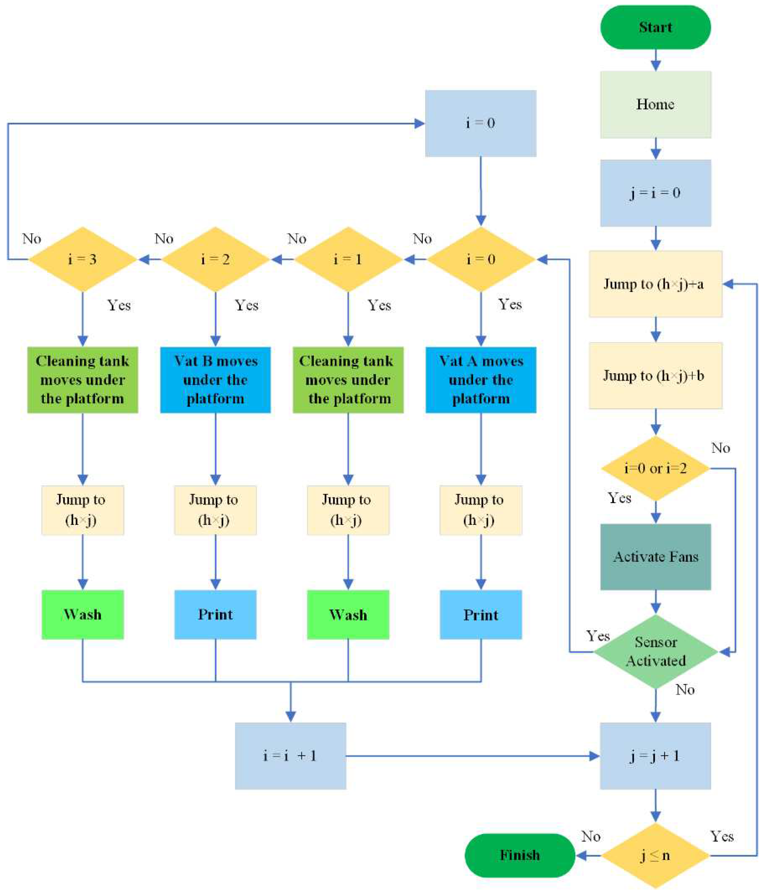
For the control of mechanisms within a multi-material setup, an Arduino Mega 2560 R3 was employed. It was necessary to sync and match the linear mechanism with the DLP 3D printer. As a result, an Inductive Proximity Sensor was utilized to send commands to the Arduino board. The proximity sensor will be activated whenever the DLP’s platform moves upward or downward. To ensure the adhesion of the sample to the DLP’s platform, some layers of resin A will be printed. However, it is imperative to note that as a result of Arduino programming, the mechanism will not move.
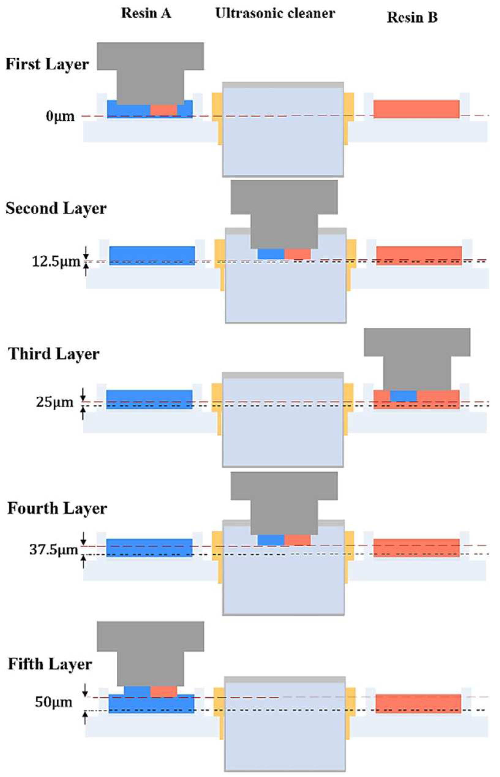
As depicted in Figure 2, the platform is elevated upon completion of the final layer of resin A, marking a relative height of 0 µm. Subsequently, the stepper motor is initiated by the sensor to start the movement of the mechanism to its next designated position, which is the cleaning station. The layer height was set to 12.5 µm. So With each platform movement, a height differential of 12.5 µm is generated. After washing process, the alcohol will be evaporated from the platform and the printed part using fans assisted by printed channels. Following the completion of each layer printing process, the subsequent stages involve the activation of the ultrasonic cleaner to wash away any excess resin. As portrayed in Figure 2, upon the printer's platform returning to its initial position, it is 50 µm higher than its original placement. In Figure 3, an algorithm is presented that illustrates switching cycles and the fabrication of multi-material samples using DLP.

2.3. D Printing Samples:

2.3.1. Parts:

To evaluate the performance of multi-material printing, three distinct groups of samples were prepared. The first group comprised three samples measuring 17.5×17.5×2 mm, which were intended to assess the capability of the printing setup for producing multi-material parts (refer to Figure 4). The second group consisted of single-material cylinder samples with a diameter of 2 mm and a height of 4 mm. These samples were prepared to investigate the influence of post-curing on the mechanical properties. The post-curing process was conducted for durations of 0, 1, 3, 6, 9, and 12 hours, with each duration being tested three times to ensure reliable results. In the third group, three dual material cubic samples were fabricated to validate the proper adhesion of interface bonding. These cubic samples possessed different angles, specifically 0, 45, and 90 degrees, and had dimensions of 4×4×4 mm. Similar to the previous group, each sample within this group was replicated three times to ensure consistency.

2.3.2. Scaffold:

Scaffold modeling:
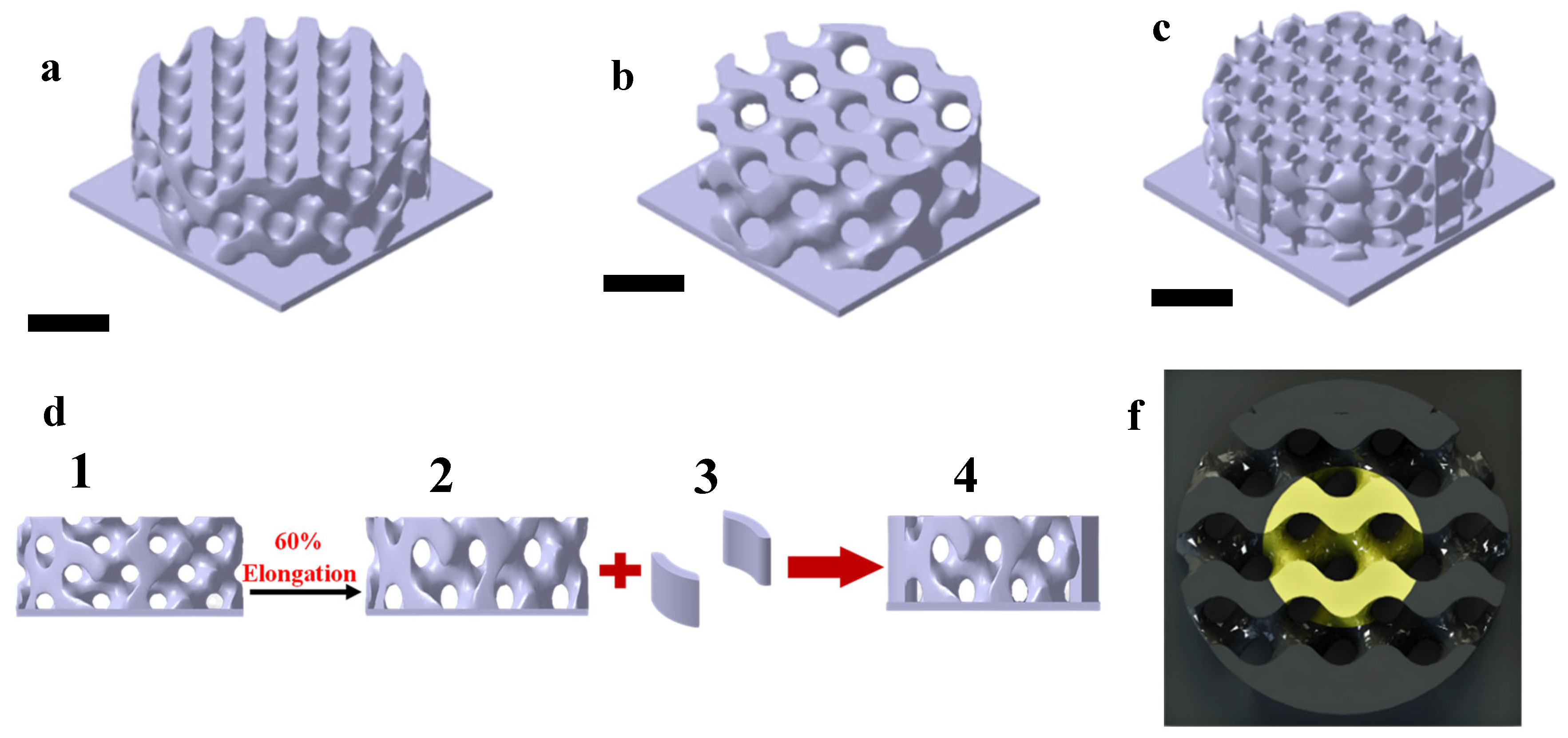
It has been demonstrated that TPMS structures are highly beneficial, as they combine both mechanical [40] and morphological properties. As well as mimicking biological bone tissue to integrate well with its surroundings [41], the TPMS structures also have sufficient mechanical strength. Consequently, some potential TPMS structures, such as Gyroid, Dimond, and Neovius (Table 1 and Figure 5a–c) [42,43,44], have been evaluated using ABAQUS and the structure with highest strength verified experimentally. After determining the highest strength of the structure through ABAQUS and experimental results, a specific TPMS structure (Figure 5d) was selected and modified by adding two columns [9] and applying 60% elongation [23] to enhance its permeability and mechanical properties [23].
K3DSurf MathMod v.8 software was used to generate the TPMS unit cells ( f   x , y , z =0, with boundary conditions of [-π, π] for x, y, and z variables), patterned and modified by CATIA V5R21. Finally, structures were generated with 60% porosity with 580 microns pore size for Gyroid and Dimond structures. Nonetheless, when two curved columns with a thickness of 750 microns were applied to the Gyroid structure, the porosity became approximately 50%. The multi-material scaffold was partitioned into two distinct sections: the outer cylinder composed of PLLA-GO, and the inner section comprising PLLA-HA, as illustrated in Figure 5f.
Fabrication of porous scaffold:
A commercial DLP 3D printer (Kavosh Ceramic, Kavosh Laser Co., Iran) was employed to print the parts and scaffolds. A DLP projector with a DMD chip with a resolution of 1024×768 pixels, each 80 × 80 µm in size, was employed. For single material and multi-material samples, the layer thickness was set at 50 µm.

2.4. Scaffold Characterization:

2.4.1. Mechanical Properties:

Compressive tests were accomplished using a universal testing machine to assess the mechanical properties of 3D-printed single and multi-material samples, according to ASTM D695 (SANTAM STM-20, Santam Co., Iran). The compressive tests were performed on samples as listed in Table 2, with 1 mm/min cross-head displacement speeds and 10 kN load cell. Moreover, the linear region of the stress-strain curve was used to calculate the elastic/compressive modulus.
samples Size (length×width×height) in mm
1 Commercial resin cylinders 2×2×4
2 Multi-material cubics 4×4×4
3 Bio resin samples (PLLA) 6×6×5
4 Bio resin cylinders (PLLA/GO) 6×6×5

2.4.2. Morphology:

Multi-material 3D printed scaffolds were assessed using Dino-Lite Digital Microscope (Dino-Light Premier, AnMo Electronics, Taiwan) in the presence of HA and GO nanoparticles. The scaffold's morphological properties and pore diameter were assessed using a Dino-Lite Digital Microscope at a magnification of 155x. The evaluation involved randomly measuring the pore diameter in ten different locations to obtain an average value. Next, a gravimetric method was used to measure the porosity of multi-material scaffolds, which was calculated using the following equation [45]:
Porosity % = V e V s + V e = ( W e 1 - W e 2 ) / ρ e W s ρ s + W e 1 - W e 2 ρ e
The actual volumes of ethanol soaked into a scaffold ( V e ) and the scaffold itself ( V s ) can be determined by measuring the weight of initial ethanol in a vessel ( W e 1 ) and the weight of ethanol left after removing the scaffold ( W e 2 ). To ensure that the alcohol thoroughly penetrates the scaffold's pores, the samples are placed in a vacuum chamber while immersed in ethanol. The weight of the scaffold (Ws), as well as the densities of the ethanol ( ρ e ) and the scaffold ( ρ s ), are also used in these calculations.

2.4.3. Cell Seeding

The PLLA/GO, PLLA/HA as single-material scaffolds, and PLLA-GO/HA as multi-material scaffolds were printed and placed in a 48-well cell culture plate and washed with distilled water and phosphate buffered saline (PBS) several times. Then, the scaffolds were sterilized using 0.5mg/ml gentamicin solution at room temperature for four hrs. The fibroblast HFF-1 as model cells were seeded (at the density 2×10⁴ cell/well) on printed scaffolds in a cell culture media containing DMEM high glucose, 1% pen-strep and 10% FBS (37 0C, 95% humidified air and 5% CO2) and left for overnight. The cells were cultured for 48 hr, with the culture medium changing daily.

2.4.4. Cell Viability

The comparison of cell viability of the HFF-1 cell line on mentioned scaffolds was determined using MTT assay as a calorimetric technique for indirect measurement of cell metabolic activity. The assay was performed after 48 hr by adding 200 µl of 0.5 mg/ml tetrazolium salt (3- (4,5-dimethylthiazol-2-yl)-3,5-diphenyl tetrazolium (MTT) solution to each well. After incubation at 37 ˚C for 4 hr, the medium was replaced with 200 µl DMSO and shaken until all the formazan crystals were dissolved. The absorbance of formazan solutions for each well was measured by a microplate reader at 570 nm.

2.4.5. Cell Morphology:

The cell morphology of HFF-1 fibroblast cells on the printed multi-material scaffold was investigated using field emission scanning electron microscope (FESEM) observations. After 48 hr, unattached cells were removed by PBS solution, and cell fixation was done using 4% formaldehyde/PBS solution. The wells were rinsed with PBS several times and samples were dehydrated using ethanol-graded series (50%, 60%, 70%, 80%, 90%, 95%, 100%). Finally, the sample was coated with gold for investigation of cell morphology on different areas of the scaffold by FESEM.

3. Result and Discussion

3.1. Multi-Material Bottom-Up Stereolithography

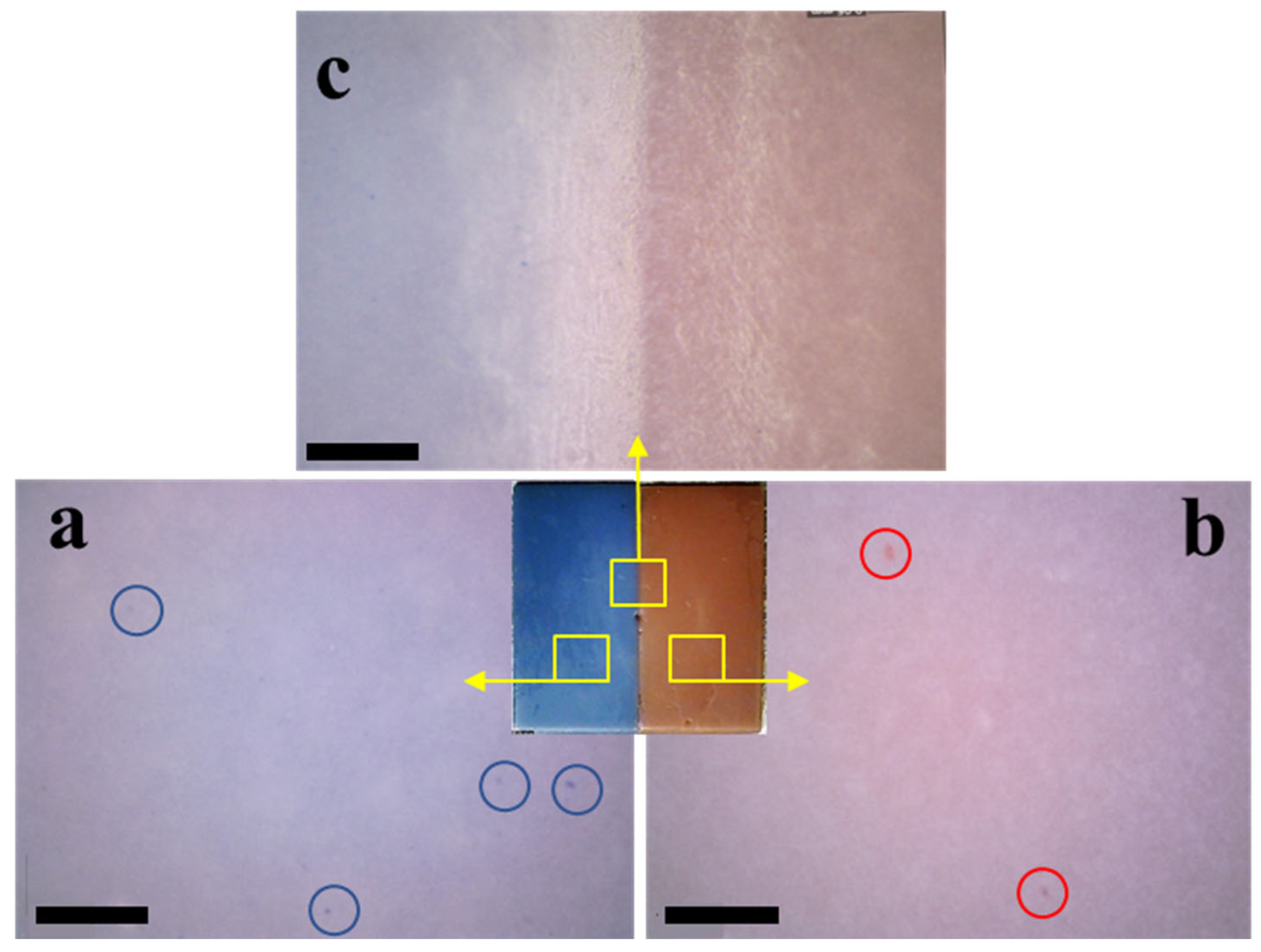
This study used a multiple-material setup that included two vats, one ultrasonic cleaning tank, and two fans. Various tests were done and programmed to determine the optimal and appropriate adjustment of the multi-material printing process. Accordingly, 36 seconds were allocated for swapping the vats and 25 seconds for drying. Figure 6 illustrates the successful printing of several multi-material parts to demonstrate the system's performance. The exposure time for the commercial resin was 16 seconds, while the exposure time for the first layer was 22 seconds. Based on the determined exposure time of 16 seconds, it was decided to set the cleaning time for the platform to the same duration. The multi-material component did not exhibit any contamination, as shown in Figure 7. Three sections of the sample are shown in Figure 7 to verify the proper function of ultrasonic cleaning during printing. Despite the successful printing of dual material parts of different designs, bubbles were observed inside the some samples lying on curves and details, which may have resulted from moisture entrapment during printing.
In Figure 7, (Figure 7a) relates to the blue area with four highlighted blue dyes, (Figure 7b) indicates the red area with two marked red dyes, and (Figure 7c) represents the separation line of the multi-material sample.
3.2.. Mechanical Properties
For both commercial and bio-resins, post-cured was required to be carried out. Also, the PLLA-GO scaffolds were subjected to various heat treatment times to evaluate their maximum strength.

3.2.1. Commercial Resin Samples:

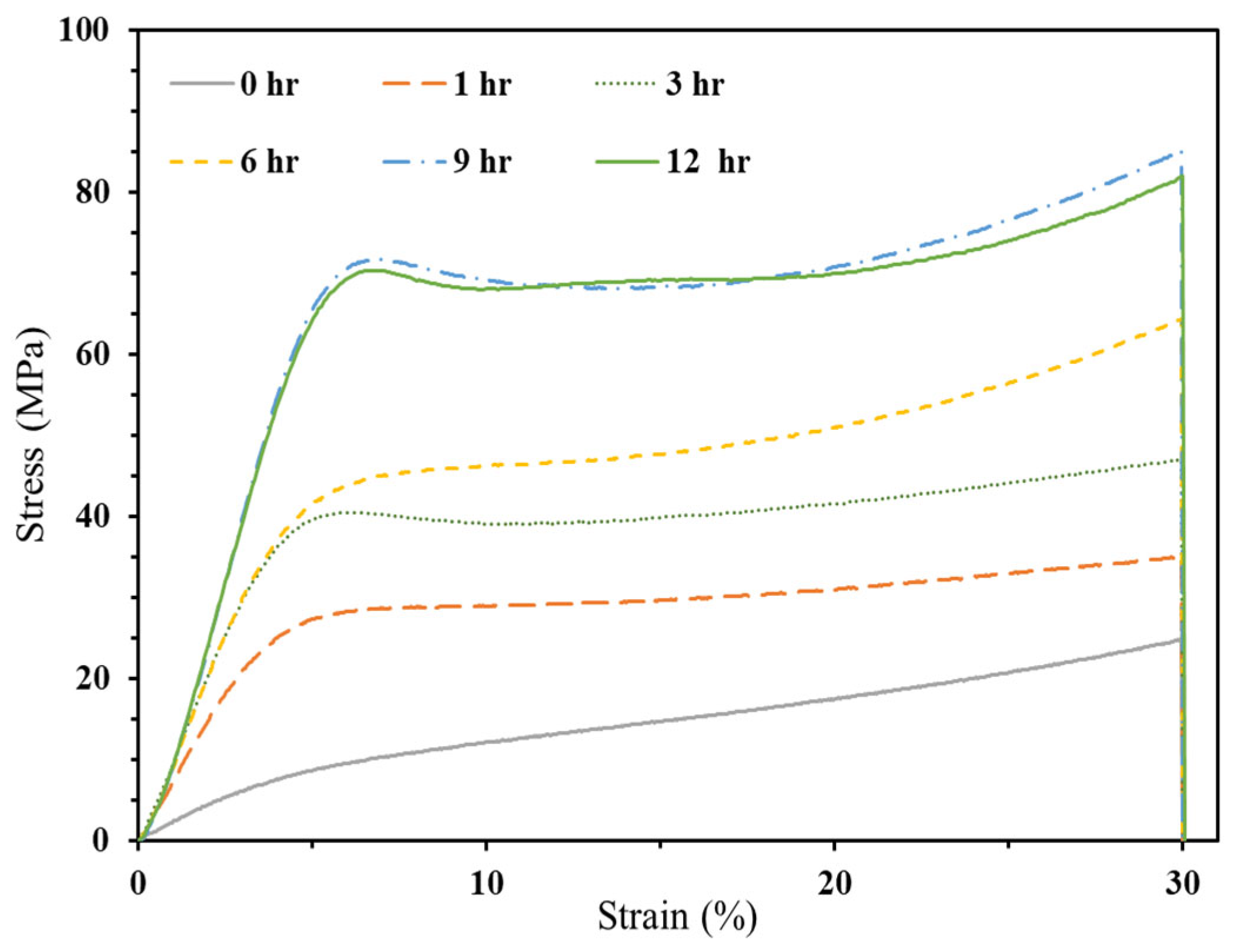
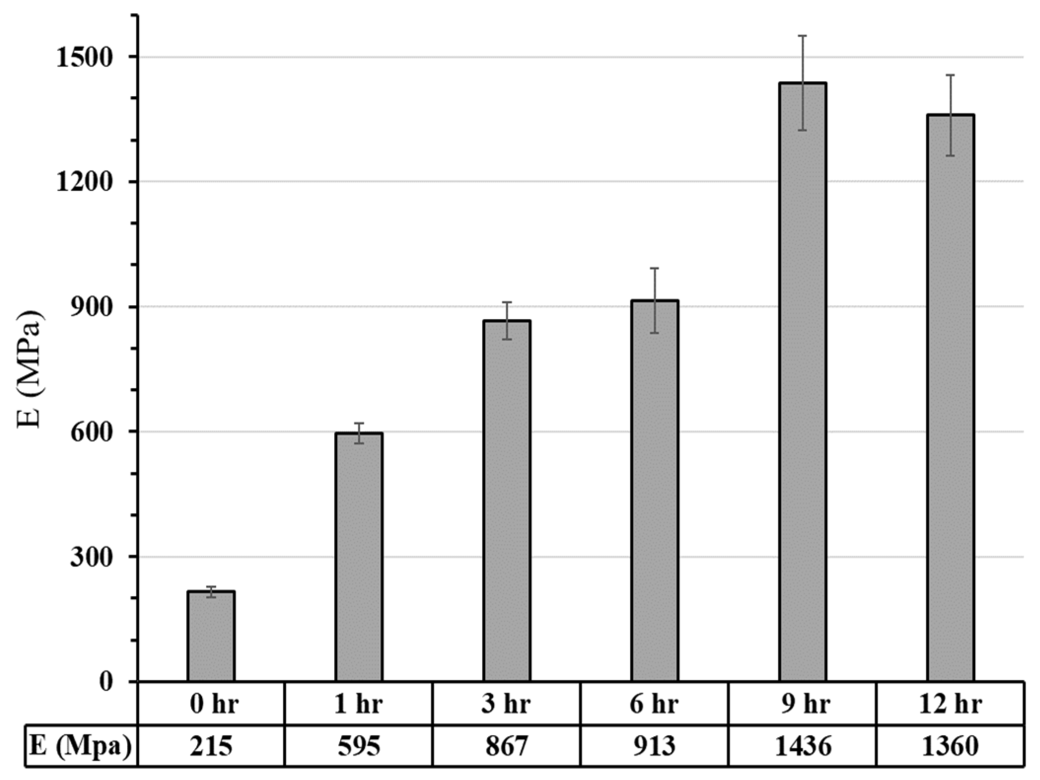
Various tests were conducted to determine the optimum post-cure time for achieving maximum strength. The compressive stress-strain curves and Young's modulus of samples at different post-curing times are illustrated in Figure 8 and Figure 9. The figures demonstrate an increase in both Young's modulus and Compressive strength by enhancing post-curing time up to 9 hours. Specifically, Young's modulus increased from 215 MPa to 1436 MPa, while the compressive strength increased from 24.8 MPa to 85.1 MPa. After nine hours of post-curing, there was no significant change in the samples' strength as a result of fully cross-linked chains.
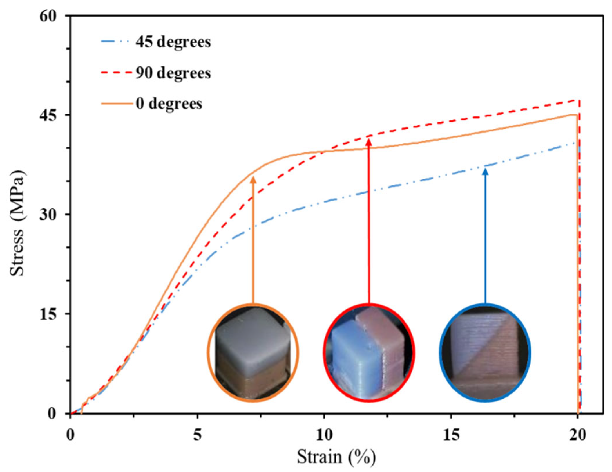
Figure 10 depicts stress-strain curves of three multi-material samples specifically printed to illustrate interface bonding. The printed cubic samples exhibited compressive strengths of 45, 41, and 47 MPa with 0°, 45°, and 90° angles, respectively, and their corresponding Young's modulus were 546, 449, and 498 MPa. The majority of differences were observed between 45 and 90 degrees, where the difference is around 15.33%.

3.2.2. Bio-Resin Samples

3.2.2.1. Compressive Strength

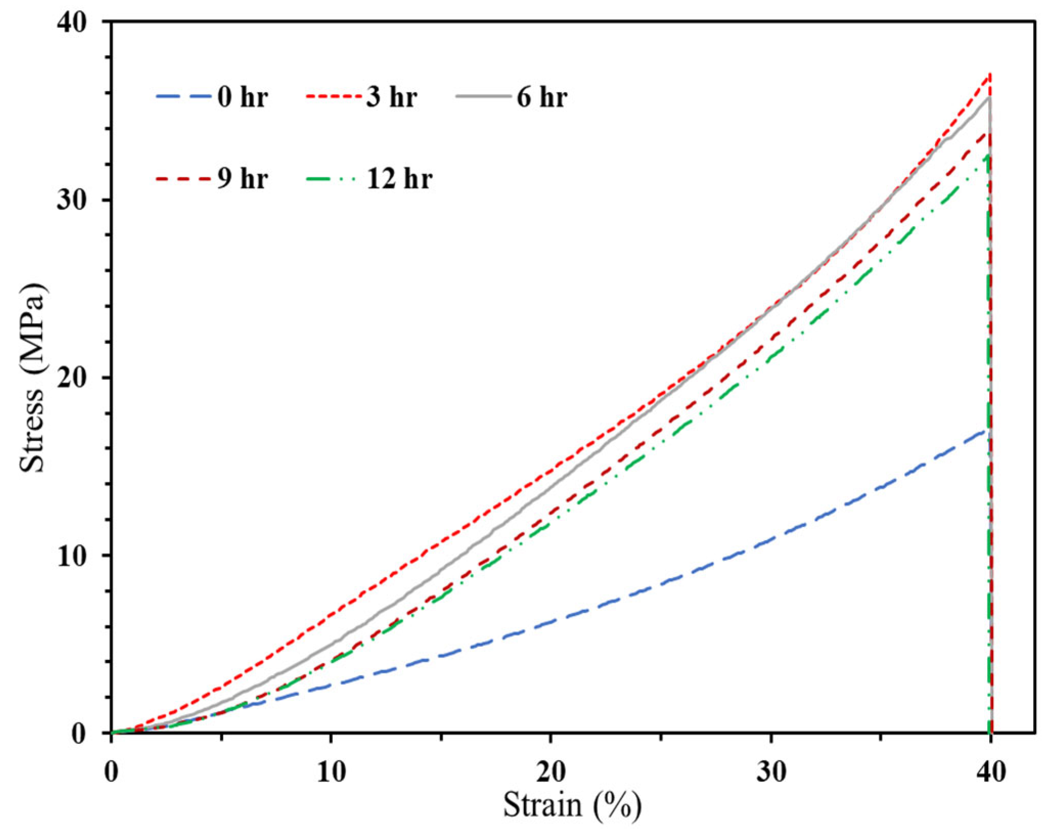
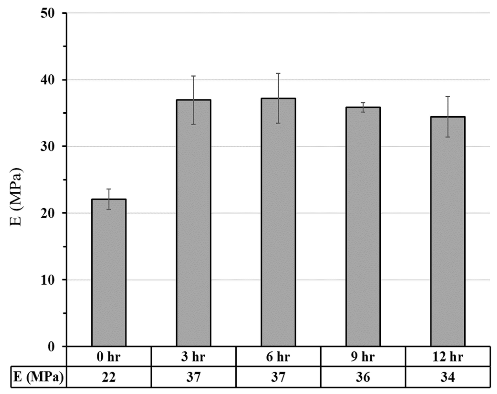
Post-cure effect: Figure 11 and Figure 12 present a comparison of compressive stress-strain curves and Young's modulus for neat PLLA samples at different post-curing times. The results show that increasing the post-curing time to 3 hours improves both compressive strength and Young's modulus, which remain stable until 6 hours. However, after 6 hours, the compressive strength decreases due to crack initiation in high shrinkage. Therefore, the most effective post-curing time for enhancing the compressive strength of neat PLLA samples is 3 hours.
Heat treatment effect:
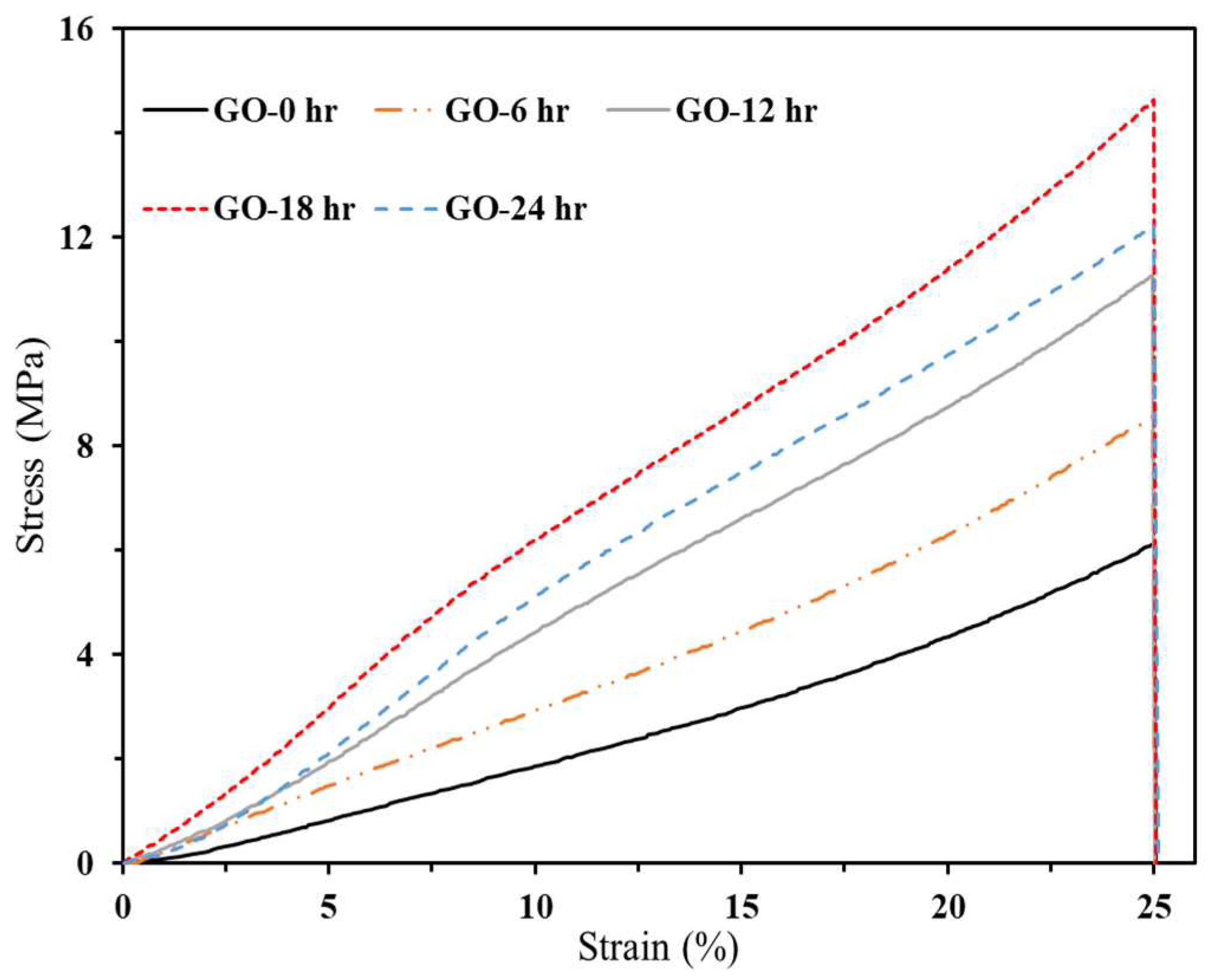
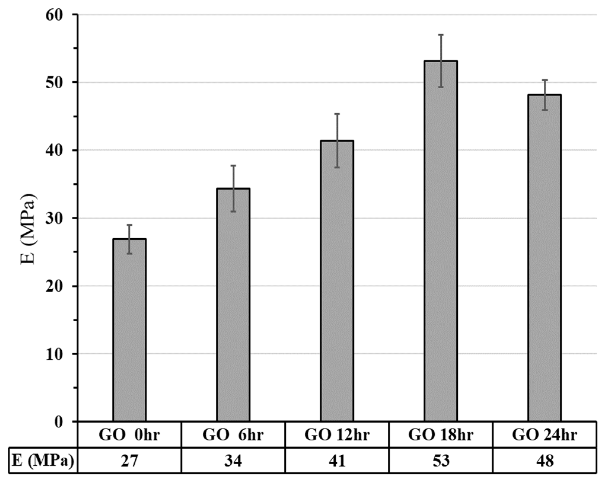
Figure 13 and Figure 14 illustrate compressive stress-strain curves and Young's modulus for PLLA/GO specimens that underwent different heat-treatment times. In this Figure, a dramatic increase in compressive strength and elastic modulus is shown for specimens with 1 wt.% of GO resulting from the increased heat treatment period. In this case, cross-links are formed between GO and PLLA chains due to the process of esterification [46], which is responsible for this phenomenon. Esterification is a chemical reaction that involves the formation of ester bonds by combining carboxyl (-COOH) groups with hydroxyl (-OH) groups. In the case of PLLA, it is a biodegradable polymer composed of lactic acid units, which contain carboxyl groups. Graphene oxide (GO) has oxygen-containing functional groups, such as hydroxyl and carboxyl groups, on its surface. During esterification, the carboxyl groups on GO can react with the hydroxyl groups on PLLA chains. This chemical reaction results in the formation of ester bonds (-COO-) between GO and PLLA, leading to cross-links between them. This effect can enhance the material's resistance to crack formation and improve its compressive strength when exposed to prolonged heat treatment. Also, the formation of cross-links is directly proportional to the percentage of GO in the material, which helps to limit excessive shrinkage of the material at high GO concentrations. Based on the results in Figure 13 and Figure 14, specimens containing 1 wt.% of GO exhibited maximum compressive strength and elastic modulus of approximately 14.6 MPa and 53 MPa, respectively, following 18 hours of heat treatment.

3.2.2.2. Finite Element Analysis

Within the Abaqus software, numerical models were constructed using the different geometries described in the STL format for the TPMS structures. The STL was used to generate a Tetrahedral Finite Element (FE) solid mesh (C3D4) to fill the surface volumes of the TPMS structure. A static/general analysis step was conducted. One rigid surface is located above the numerical models, measuring 10×10 mm. The lower surface of TPMS structures defined a fully-fixed constraint. In contrast, the upper surface applied a fully-fixed constraint with a reference point towards z (the compressive direction) by a 0.3 mm/min constant speed. The contact between the TPMS elements and the bounding surfaces was frictionless as well.
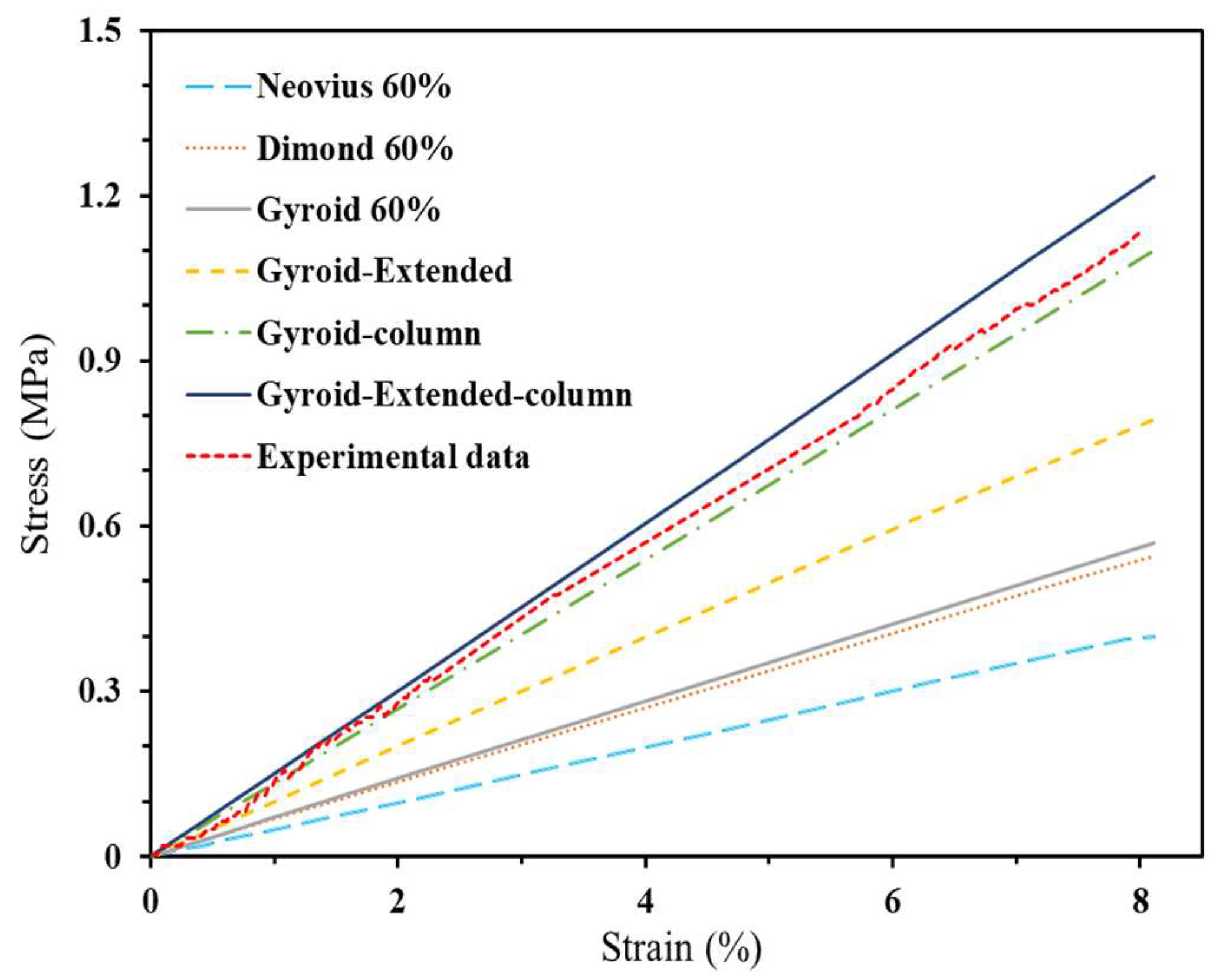
Moreover, the mechanical properties of the material were characterized by Young's modulus of 37 MPa and Poisson's ratio of 0.33.Additionally, the optimal structure with the best strength was chosen to print in order to assess and validate the numerical analysis. Figure 14 represents the strain-stress data obtained from numerical analysis and experimental testing for the structure with highest strength to determine Young's modulus and compressive strength.
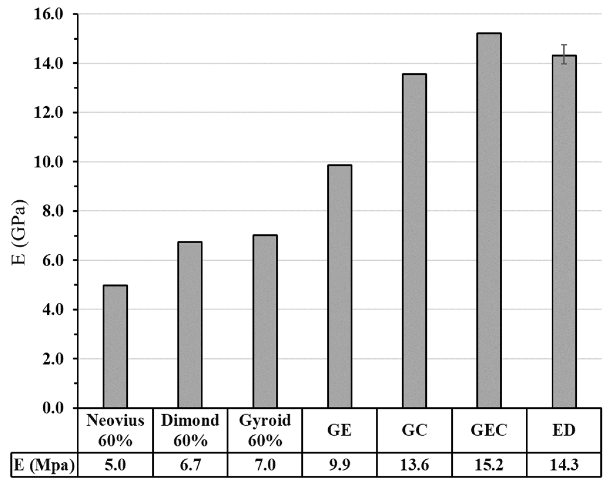
Figure 15 presents a comparison of the mechanical strength of three TPMS structures, Neovius, Dimond, and Gyroid, with 60% porosity. The compressive strength of Gyroid and Dimond was nearly the same, at 0.56 and 0.54 MPa, respectively, while Neovius had the lowest compressive strength of 0.40 MPa. Gyroid also exhibited a Young's modulus that was 4% and 30% greater than that of Dimond and Neovius, respectively. Given the higher mechanical properties and permeability [47] of Gyroid, it was chosen for further investigation. By adding two columns [35], the porosity of Gyroid was reduced from 60% to 50%, resulting in a 59.30% increase in compressive strength Moreover, applying 60% elongation to a simple gyroid with 60% porosity enhanced the mechanical strength at 0.08 strain from 0.57 to 0.79 MPa, according to [23]. As a final step, a gyroid with 50% porosity, two columns, and 60% elongation was analyzed, resulting in a Young's modulus and compressive strength of 15.23 MPa and 1.24 MPa, respectively. To validate the numerical analysis, a gyroid with two columns and 60% elongation was printed. The printed samples validated the numerical analysis with errors of 6.36% and 9.39% in Young's modulus and compressive strength, respectively, as shown in Figure 16. In this figure, GE stands for Gyroid with 60% Elongation, GC means Gyroid with 2 Columns, GEC is the mix of Gyroid, elongation and columns, and ED refers to the experimental data.

3.3. Scaffolds Morphology

Table 3 presents a comparison between the nominal porosity and calculated porosity, as well as the pore size measurements of printed samples. To examine porosity and pore size in a multi-material process, PLLA-PLLA and PLLA/GO-HA multi-material samples were printed and analyzed, as shown in Figure 17. The nominal porosity and pore sizes were 50% and 580 µm, respectively, while the measured porosity and pore size of PLLA-PLLA were about 47% and 547 µm, respectively. The PLLA/GO-HA multi-material specimens had a porosity of around 43% and an average pore size of 454 µm. The average pore size of the multi-material scaffold was found to be below 500 µm. It has been reported that pore sizes between 300 and 500 microns are highly suitable for cell growth, vascularization, adhesion, and regeneration of new bone [18]. There was a reduction of about 14% in both porosities of PLLA-PLLA and PLLA/GO-HA multi-material samples. However, PLLA-PLLA multi-material pore sizes had a lower error of 5.7% due to over-cure of the PLLA resin. In contrast, the PLLA/GO-HA multi-material sample had a higher pore size error of 21.9% due to both over-cure and shrinkage induced by heat treatment.

3.4. In Vitro Studies

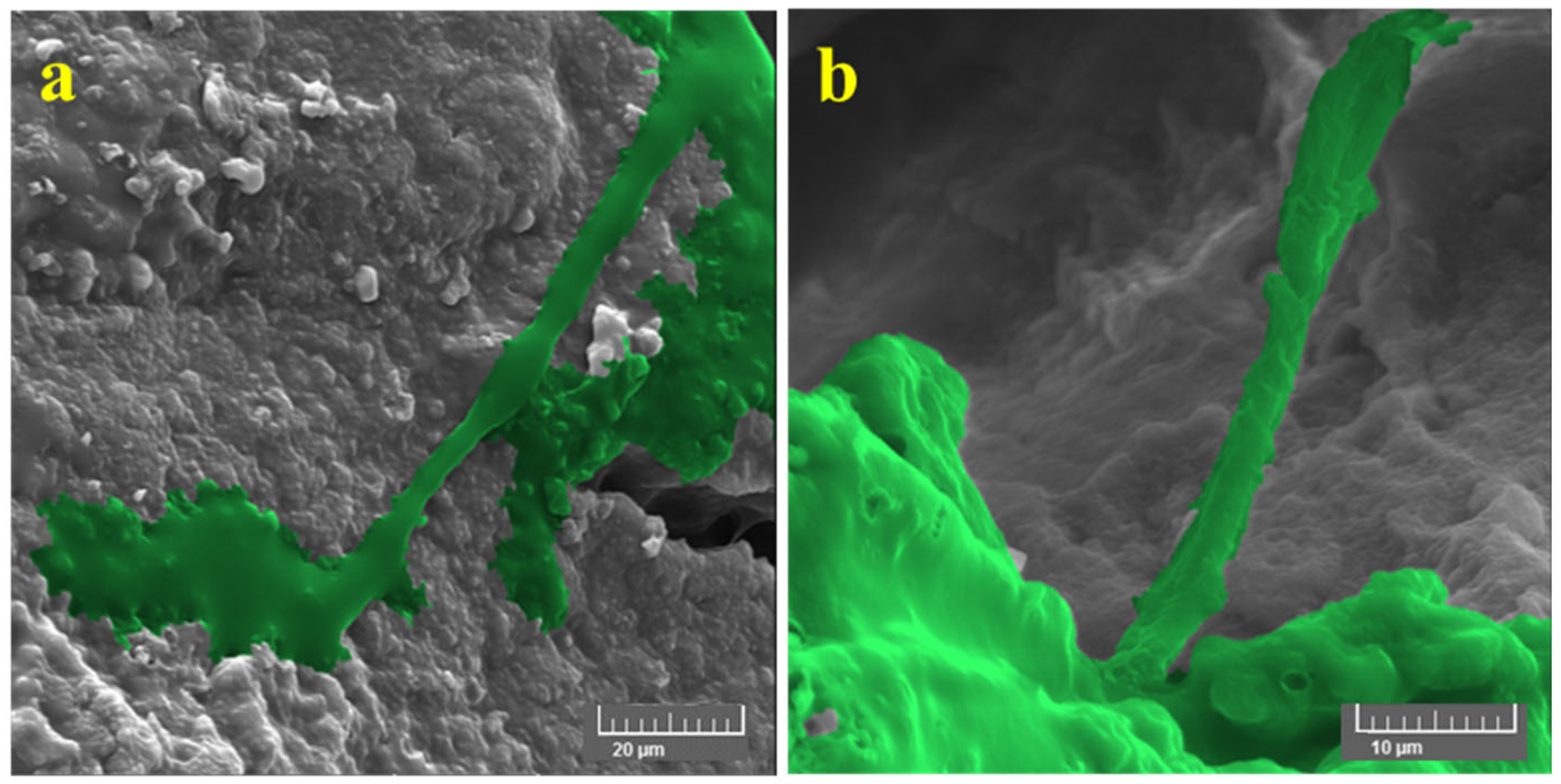
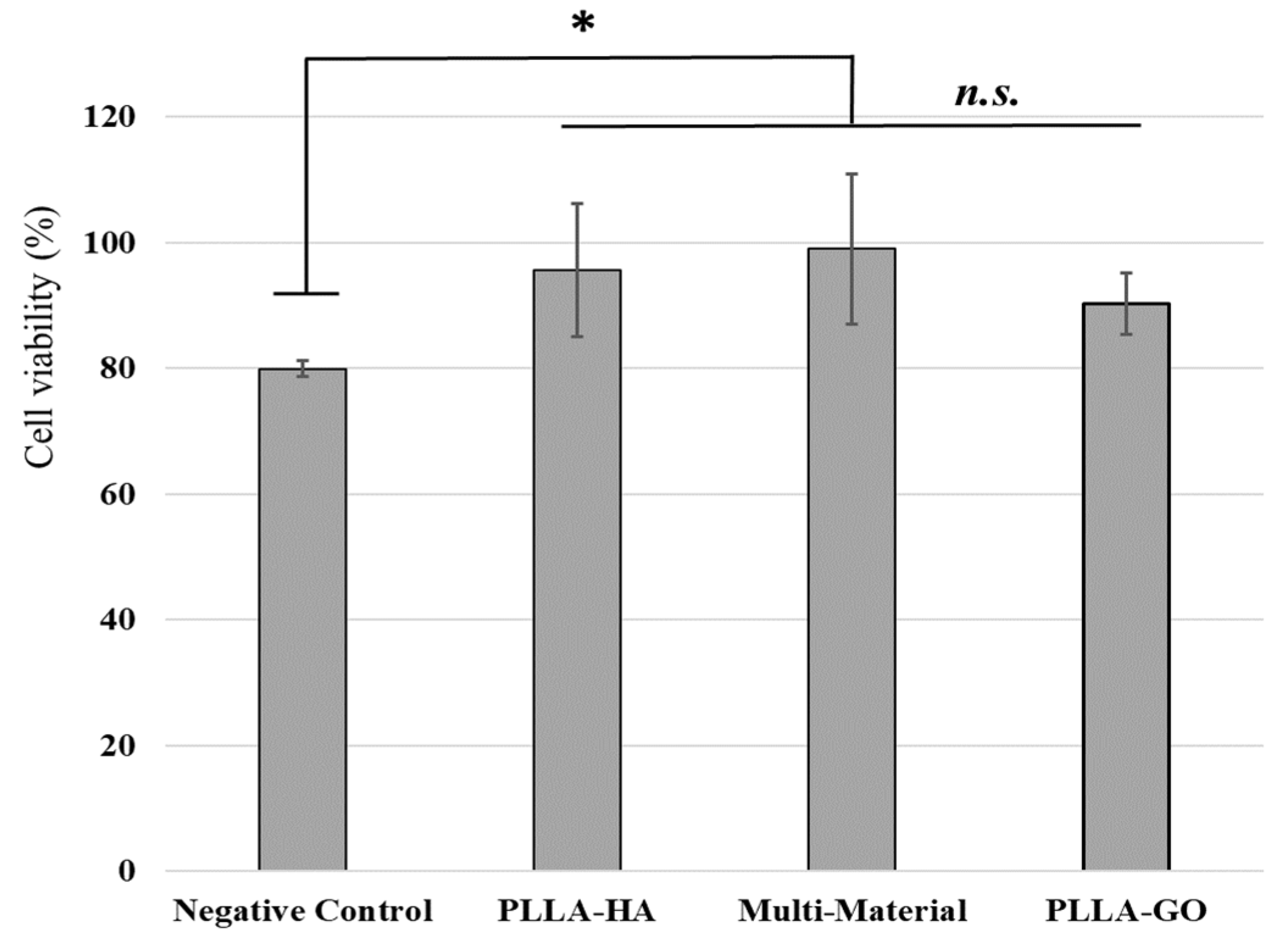
The cytotoxicity assay of the multi-material scaffold was performed via MTT assay technique and compared with single-material scaffolds as positive controls. The polyester-coated wells of the cell culture plate were considered a negative control. The test was performed using a human foreskin fibroblast-1 (HFF-1) cell line as a model system to assess the cytotoxicity of 3D-printed scaffolds. The fibroblast cells are used as standard cells to determine the toxicity of materials and equipment used in dental applications. The HFF-1 cells have been used in various scaffold-based approaches for tissue engineering and regenerative medicine applications (both hard and soft tissue) [48,49]. Also, HFF-1 cell lines are used as a model system to investigate the cellular and molecular mechanisms of regeneration and formation of osteogenic differentiation [50]. Figure 16 shows the viability results of HFF-1 cells on printed scaffolds. The results demonstrated that the use of PLLA/GO-HA multi-material scaffold has significantly increased cell viability and proliferation (p≤ .05). Supplementary studies on the cellular morphology of HFF-1 cells on a multi-material scaffold was performed using FESEM observations. Figure 17a depicts the natural morphology and cell-cell junction on the graphene oxide area of a 3D printed multi-material scaffold. Additionally, Figure 17b showcases a similar connection observed in the hydroxyapatite area of the scaffold. These images confirm the printing of a suitable biocompatible scaffold for proliferation and a cellular connection to form new tissue.
Figure 19. FESEM images of attached cells on a multi-material scaffold on copper tape, (a) graphene oxide section and (b) hydroxyapatite section.
Preprints 90278 g019

4. Conclusion

This study aimed to improve the mechanical and biological properties of scaffolds for dental bone loss applications. An optimized TPMS scaffold was developed using ABAQUS, and PLLA-HA and PLLA-GO were printed with a multi-material setup on the DLP 3D printer. Performance of the multi-material setup was verified through the successful printing and evaluation of several dual-material samples. The samples were also found to have the least amount of contamination due to ultrasonic cleaning. The optimal post-cure time for commercial resin was determined to be 9 hours based on high compressive strength and Young's modulus. Moreover, bonding strength tests revealed the considerable strength of the interface fabricated by multi-material setup via DLP. Also, due to the formation of ester bonds between GO and PLLA, increasing the heat treatment time of PLLA with 1% GO resulted in a significant increase in compressive strength until 18 hours. In contrast, after 18 hours, there was a reduction in compressive strength as a result of cracks resulting from shrinkage. Employing finite element analysis, an optimized Gyroid with 50% porosity was developed, providing a 54% increase in compressive strength compared to a basic Gyroid with 60% porosity. The PLLA/GO-HA scaffold was also found to be non-cytotoxic in the MTT assay, with strong cell adhesion. Finally, the increase in the number of vats and cleaning stages in vat photopolymerization 3D printing technologies, such as DLP, can significantly contribute to the development of advanced scaffolds for dental bone loss and other biomedical applications. These scaffolds can be produced with a variety of materials, intricate designs, and high resolution, catering to the specific needs of individual patients.

References

  1. Dzobo, K.; Thomford, N.E.; Senthebane, D.A.; Shipanga, H.; Rowe, A.; Dandara, C.; Pillay, M.; Motaung, K.S.C.M. Advances in regenerative medicine and tissue engineering: Innovation and transformation of medicine. Stem Cells Int. 2018, 2018, 2495848. [Google Scholar] [CrossRef] [PubMed]
  2. Derakhshanfar, S.; Mbeleck, R.; Xu, K.; Zhang, X.; Zhong, W.; Xing, M. 3D bioprinting for biomedical devices and tissue engineering: A review of recent trends and advances. Bioact. Mater. 2018, 3, 144–156. [Google Scholar] [CrossRef] [PubMed]
  3. Xu, T.; Miszuk, J.M.; Zhao, Y.; Sun, H.; Fong, H. Electrospun Polycaprolactone 3D Nanofibrous Scaffold with Interconnected and Hierarchically Structured Pores for Bone Tissue Engineering. Adv. Heal. Mater. 2015, 4, 2238–2246. [Google Scholar] [CrossRef] [PubMed]
  4. Arabpour, Z.; Baradaran-Rafii, A.; Bakhshaiesh, N.L.; Ai, J.; Ebrahimi-Barough, S.; Malekabadi, H.E.; Nazeri, N.; Vaez, A.; Salehi, M.; Sefat, F.; et al. Design and characterization of biodegradable multi layered electrospun nanofibers for corneal tissue engineering applications. J. Biomed. Mater. Res. Part A 2019, 107, 2340–2349. [Google Scholar] [CrossRef] [PubMed]
  5. Özarslan, A.C.; Yücel, S. Fabrication and characterization of strontium incorporated 3-D bioactive glass scaffolds for bone tissue from biosilica. Mater. Sci. Eng. C 2016, 68, 350–357. [Google Scholar] [CrossRef] [PubMed]
  6. Davidenko, N.; Schuster, C.F.; Bax, D.V.; Raynal, N.; Farndale, R.W.; Best, S.M.; Cameron, R.E. Control of crosslinking for tailoring collagen-based scaffolds stability and mechanics. Acta Biomater. 2015, 25, 131–142. [Google Scholar] [CrossRef] [PubMed]
  7. Alonzo, M.; Primo, F.A.; Kumar, S.A.; Mudloff, J.A.; Dominguez, E.; Fregoso, G.; Ortiz, N.; Weiss, W.M.; Joddar, B. Bone tissue engineering techniques, advances, and scaffolds for treatment of bone defects. Curr. Opin. Biomed. Eng. 2020, 17, 100248. [Google Scholar] [CrossRef]
  8. Hunziker, E.; Lippuner, K.; Keel, M.; Shintani, N. An educational review of cartilage repair: precepts & practice – myths & misconceptions – progress & prospects. Osteoarthr. Cartil. 2015, 23, 334–350. [Google Scholar] [CrossRef]
  9. Saed, A.B.; Behravesh, A.H.; Hasannia, S.; Akhoundi, B.; Hedayati, S.K.; Gashtasbi, F. An in vitro study on the key features of Poly L-lactic acid/biphasic calcium phosphate scaffolds fabricated via DLP 3D printing for bone grafting. Eur. Polym. J. 2020, 141, 110057. [Google Scholar] [CrossRef]
  10. Cox, S.C.; Thornby, J.A.; Gibbons, G.J.; Williams, M.A.; Mallick, K.K. 3D printing of porous hydroxyapatite scaffolds intended for use in bone tissue engineering applications. Mater. Sci. Eng. C 2015, 47, 237–247. [Google Scholar] [CrossRef]
  11. Gholivand, K.; Ardebili, S.A.A.; Mohammadpour, M.; Malekshah, R.E.; Hasannia, S.; Onagh, B. Preparation and examination of a scaffold based on hydroxylated polyphosphazene for tissue engineering: In vitro and in vivo studies. J. Appl. Polym. Sci. 2022, 139, 52179. [Google Scholar] [CrossRef]
  12. Chen, R.; Wang, J.; Liu, C. Biomaterials Act as Enhancers of Growth Factors in Bone Regeneration. Adv. Funct. Mater. 2016, 26, 8810–8823. [Google Scholar] [CrossRef]
  13. Nie, W.; Peng, C.; Zhou, X.; Chen, L.; Wang, W.; Zhang, Y.; Ma, P.X.; He, C. Three-dimensional porous scaffold by self-assembly of reduced graphene oxide and nano-hydroxyapatite composites for bone tissue engineering. Carbon 2017, 116, 325–337. [Google Scholar] [CrossRef]
  14. Yagihara, K.; Okabe, S.; Ishii, J.; Amagasa, T.; Yamashiro, M.; Yamaguchi, S.; Yokoya, S.; Yamazaki, T.; Kinoshita, Y. Mandibular reconstruction using a poly(l-lactide) mesh combined with autogenous particulate cancellous bone and marrow: a prospective clinical study. Int. J. Oral Maxillofac. Surg. 2013, 42, 962–969. [Google Scholar] [CrossRef]
  15. Al-Wafi, R.; Mansour, S.; Ahmed, M. Mechanical, microstructural properties and cell adhesion of Sr/Se-hydroxyapatite/graphene/polycaprolactone nanofibers. J. Thermoplast. Compos. Mater. 2020, 34, 536–556. [Google Scholar] [CrossRef]
  16. Grant, J.J.; Pillai, S.C.; Hehir, S.; McAfee, M.; Breen, A. Biomedical Applications of Electrospun Graphene Oxide. ACS Biomater. Sci. Eng. 2021, 7, 1278–1301. [Google Scholar] [CrossRef] [PubMed]
  17. Moyano, J.; Mosa, J.; Aparicio, M.; Pérez-Coll, D.; Belmonte, M.; Miranzo, P.; Osendi, M. Corrigendum to “Strong and light cellular silicon carbonitride – Reduced graphene oxide material with enhanced electrical conductivity and capacitive response’’ [Addit. Manuf. 30 (2019) 100849]. Addit. Manuf. 2020, 32. [Google Scholar] [CrossRef]
  18. Karageorgiou, V.; Kaplan, D. Porosity of 3D biomaterial scaffolds and osteogenesis. Biomaterials 2005, 26, 5474–5491. [Google Scholar] [CrossRef] [PubMed]
  19. Loh, Q.L.; Choong, C. Three-Dimensional Scaffolds for Tissue Engineering Applications: Role of Porosity and Pore Size. Tissue Eng. Part B: Rev. 2013, 19, 485–502. [Google Scholar] [CrossRef]
  20. Amini, A.R.; Laurencin, C.T.; Nukavarapu, S.P. Bone Tissue Engineering: Recent Advances and Challenges. Crit. Rev. Biomed. Eng. 2012, 40, 363–408. [Google Scholar] [CrossRef]
  21. Roseti, L.; Parisi, V.; Petretta, M.; Cavallo, C.; Desando, G.; Bartolotti, I.; Grigolo, B. Scaffolds for Bone Tissue Engineering: State of the art and new perspectives. Mater. Sci. Eng. C 2017, 78, 1246–1262. [Google Scholar] [CrossRef]
  22. Melchels, F.P.W.; Barradas, A.W.C.; van Blitterswijk, C.A.; de Boer, J.; Feijen, J.; Grijpma, D.W. Effects of the architecture of tissue engineering scaffolds on cell seeding and culturing. Acta Biomater. 2010, 6, 4208–4217. [Google Scholar] [CrossRef]
  23. Lee, J.-W.; Lee, Y.-H.; Lee, H.; Koh, Y.-H.; Kim, H.-E. Improving mechanical properties of porous calcium phosphate scaffolds by constructing elongated gyroid structures using digital light processing. Ceram. Int. 2020, 47, 3252–3258. [Google Scholar] [CrossRef]
  24. Jin, Y.; Zou, S.; Pan, B.; Li, G.; Shao, L.; Du, J. Biomechanical properties of cylindrical and twisted triply periodic minimal surface scaffolds fabricated by laser powder bed fusion. Addit. Manuf. 2022, 56, 102899. [Google Scholar] [CrossRef]
  25. Zhang, X.-Y.; Yan, X.-C.; Fang, G.; Liu, M. Biomechanical influence of structural variation strategies on functionally graded scaffolds constructed with triply periodic minimal surface. Addit. Manuf. 2020, 32, 101015. [Google Scholar] [CrossRef]
  26. Melchels, F.P.W.; Barradas, A.W.C.; van Blitterswijk, C.A.; de Boer, J.; Feijen, J.; Grijpma, D.W. Effects of the architecture of tissue engineering scaffolds on cell seeding and culturing. Acta Biomater. 2010, 6, 4208–4217. [Google Scholar] [CrossRef] [PubMed]
  27. Feng, J.; Fu, J.; Yao, X.; He, Y. Triply periodic minimal surface (TPMS) porous structures: from multi-scale design, precise additive manufacturing to multidisciplinary applications. Int. J. Extreme Manuf. 2022, 4, 022001. [Google Scholar] [CrossRef]
  28. THE JOURNAL OF Prosthetic Dentistry. J. Prosthet. Dent. 2000, 84, 8A. [CrossRef]
  29. Xing, Z.; Zhou, H.; Liu, W.; Nie, J.; Chen, Y.; Li, W. Efficient cleaning of ceramic green bodies with complex architectures fabricated by stereolithography-based additive manufacturing via high viscoelastic paste. Addit. Manuf. 2022, 55, 102809. [Google Scholar] [CrossRef]
  30. Hu, K.; Zhao, P.; Li, J.; Lu, Z. High-resolution multiceramic additive manufacturing based on digital light processing. Addit. Manuf. 2022, 54, 102732. [Google Scholar] [CrossRef]
  31. Melchels, F.P.W.; Feijen, J.; Grijpma, D.W. A review on stereolithography and its applications in biomedical engineering. Biomaterials 2010, 31, 6121–6130. [Google Scholar] [CrossRef]
  32. Melchels, F.P.W.; Feijen, J.; Grijpma, D.W. A review on stereolithography and its applications in biomedical engineering. Biomaterials 2010, 31, 6121–6130. [Google Scholar] [CrossRef]
  33. Zhou, C.; Chen, Y.; Yang, Z.; Khoshnevis, B. Digital material fabrication using mask-image-projection-based stereolithography. Rapid Prototyp. J. 2013, 19, 153–165. [Google Scholar] [CrossRef]
  34. Fuchs, F.J. Ultrasonic cleaning and washing of surfaces. In Power Ultrasonics; Elsevier Ltd.: Amsterdam, The Netherlands, 2015; pp. 577–609. [Google Scholar]
  35. Saed, A.B.; Behravesh, A.H.; Hasannia, S.; Ardebili, S.A.A.; Akhoundi, B.; Pourghayoumi, M. Functionalized poly L-lactic acid synthesis and optimization of process parameters for 3D printing of porous scaffolds via digital light processing (DLP) method. J. Manuf. Process. 2020, 56, 550–561. [Google Scholar] [CrossRef]
  36. Wu, X.; Lian, Q.; Li, D.; Jin, Z. Biphasic osteochondral scaffold fabrication using multi-material mask projection stereolithography. Rapid Prototyp. J. 2019, 25, 277–288. [Google Scholar] [CrossRef]
  37. Choi, J.-W.; MacDonald, E.; Wicker, R. Multi-material microstereolithography. Int. J. Adv. Manuf. Technol. 2009, 49, 543–551. [Google Scholar] [CrossRef]
  38. Matte, C.-D.; Pearson, M.; Trottier-Cournoyer, F.; Dafoe, A.; Kwok, T.-H. Multi-material digital light processing printer with material tower and spray cleaning. ASME 2018 13th Int. Manuf. Sci. Eng. Conf. MSEC 2018, vol. 4, pp. 1–11, 2018. [CrossRef]
  39. Choi, J.-W.; Kim, H.-C.; Wicker, R. Multi-material stereolithography. J. Am. Acad. Dermatol. 2011, 211, 318–328. [Google Scholar] [CrossRef]
  40. Guo, X.; Zheng, X.; Yang, Y.; Yang, X.; Yi, Y. Mechanical behavior of TPMS-based scaffolds: a comparison between minimal surfaces and their lattice structures. SN Appl. Sci. 2019, 1, 1145. [Google Scholar] [CrossRef]
  41. Fantini, M.; Curto, M.; De Crescenzio, F. TPMS for interactive modelling of trabecular scaffolds for bone tissue engineering. Lect. Notes Mech. Eng. 2017, 425–435. [Google Scholar] [CrossRef]
  42. Schoen, A.H. Reflections concerning triply-periodic minimal surfaces. Interface Focus 2012, 2, 658–668. [Google Scholar] [CrossRef] [PubMed]
  43. Blanquer, S.B.G.; Werner, M.; Hannula, M.; Sharifi, S.; Lajoinie, G.P.R.; Eglin, D.; Hyttinen, J.; A Poot, A.; Grijpma, D.W. Surface curvature in triply-periodic minimal surface architectures as a distinct design parameter in preparing advanced tissue engineering scaffolds. Biofabrication 2017, 9, 025001. [Google Scholar] [CrossRef] [PubMed]
  44. Wohlgemuth, M.; Yufa, N.; Hoffman, J.; Thomas, E.L. Triply Periodic Bicontinuous Cubic Microdomain Morphologies by Symmetries. Macromolecules 2001, 34, 6083–6089. [Google Scholar] [CrossRef]
  45. Hedayati, S.K.; Behravesh, A.H.; Hasannia, S.; Kordi, O.; Pourghaumi, M.; Saed, A.B.; Gashtasbi, F. Additive manufacture of PCL/nHA scaffolds reinforced with biodegradable continuous Fibers: Mechanical Properties, in-vitro degradation Profile, and cell study. Eur. Polym. J. 2022, 162, 110876. [Google Scholar] [CrossRef]
  46. Manapat, J.Z.; Mangadlao, J.D.; Tiu, B.D.B.; Tritchler, G.C.; Advincula, R.C. High-Strength Stereolithographic 3D Printed Nanocomposites: Graphene Oxide Metastability. ACS Appl. Mater. Interfaces 2017, 9, 10085–10093. [Google Scholar] [CrossRef] [PubMed]
  47. Diez-Escudero, A.; Harlin, H.; Isaksson, P.; Persson, C. Porous polylactic acid scaffolds for bone regeneration: A study of additively manufactured triply periodic minimal surfaces and their osteogenic potential. J. Tissue Eng. 2020, 11. [Google Scholar] [CrossRef] [PubMed]
  48. Cipriani, F.; Krüger, M.; de Torre, I.G.; Sierra, L.Q.; Rodrigo, M.A.; Kock, L.; Rodriguez-Cabello, J.C. Cartilage Regeneration in Preannealed Silk Elastin-Like Co-Recombinamers Injectable Hydrogel Embedded with Mature Chondrocytes in an Ex Vivo Culture Platform. Biomacromolecules 2018, 19, 4333–4347. [Google Scholar] [CrossRef] [PubMed]
  49. Li, Z.; Xie, M.-B.; Li, Y.; Ma, Y.; Li, J.-S.; Dai, F.-Y. Recent Progress in Tissue Engineering and Regenerative Medicine. J. Biomater. Tissue Eng. 2016, 6, 755–766. [Google Scholar] [CrossRef]
  50. Monterubbianesi, R.; Bencun, M.; Pagella, P.; Woloszyk, A.; Orsini, G.; Mitsiadis, T.A. A comparative in vitro study of the osteogenic and adipogenic potential of human dental pulp stem cells, gingival fibroblasts and foreskin fibroblasts. Sci. Rep. 2019, 9, 1–13. [Google Scholar] [CrossRef]
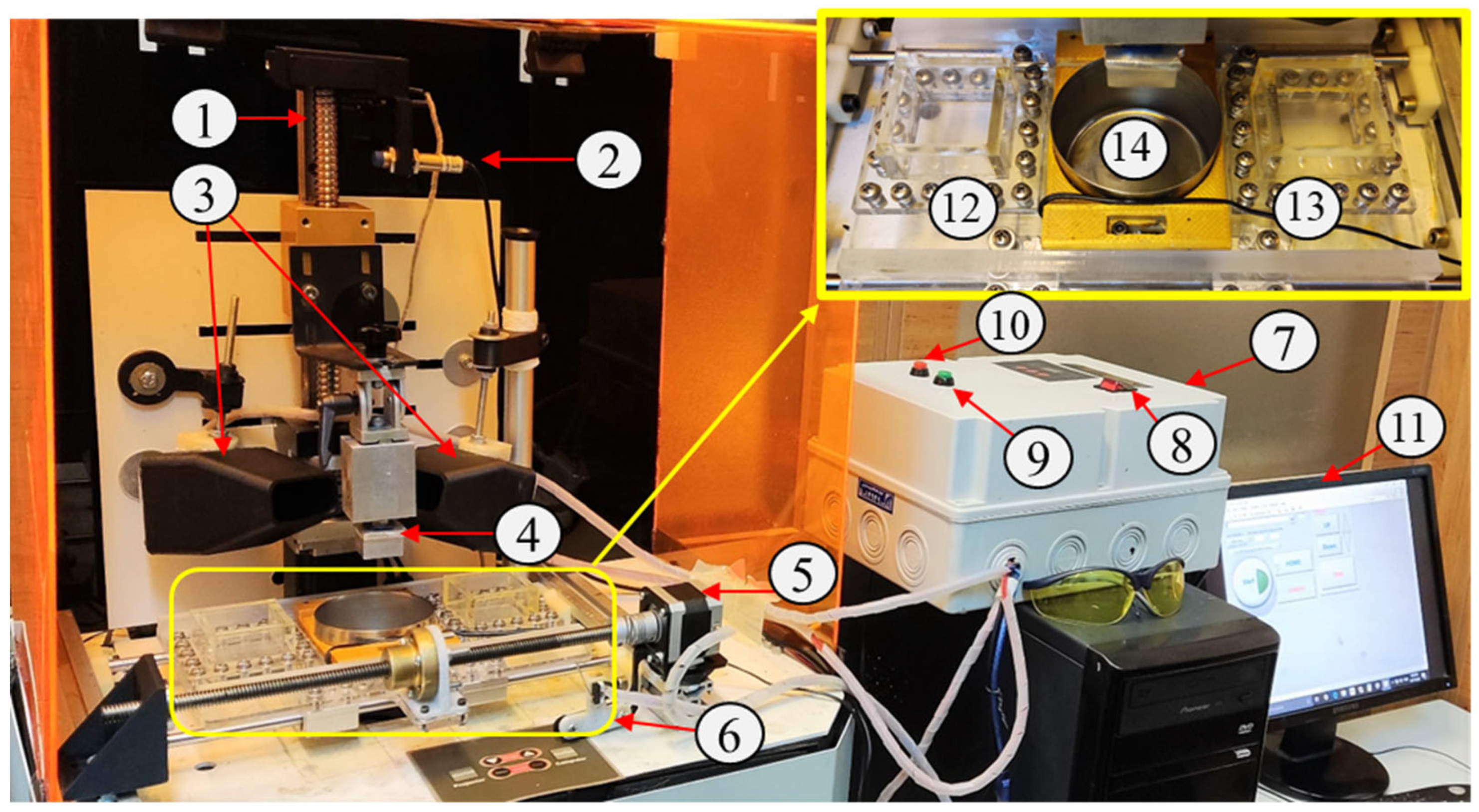
Figure 1. Multi-material DLP.
Preprints 90278 g001
Figure 2. Multi-material setup printing.
Preprints 90278 g002
Figure 3. Multi-material algorithm, A, b, h, and j represent the total number of layers, the first jump fixed height, the second jump fixed height, the layer height, and the layer count, respectively.
Preprints 90278 g003
Figure 4. Designed multi-material samples (a, c) Full sample (b) cross-section sample (All with a scale of 4.5 mm).
Preprints 90278 g004
Figure 5. Isometric views of TPMS structures, namely (a) Dimond, (b) Gyroid, (c) Neovius (All with 2mm scale), (d) Process of generating the optimum scaffold (f) Top view of multi-material scaffold (PLLA/ GO-PLLA/HA).
Preprints 90278 g005
Figure 6. Multi-material printed Components (a,c) Full sample (b) cross-section of cut sample (All with a scale of 2.5 mm).
Preprints 90278 g006
Figure 7. Zoomed-in views of a multi-material sample, all with 0.1 mm scale.
Preprints 90278 g007
Figure 8. Stress-Strain curves of post-cured samples by commercial resin.
Preprints 90278 g008
Figure 9. Young Modulus (GPa) of commercial resin samples for various post-curing times.
Preprints 90278 g009
Figure 10. Stress-strain curves of multi-material parts with angles of 0, 45, and 90 degrees.
Preprints 90278 g010
Figure 11. Stress-strain curves of neat PLLA specimens for various post-curing times.
Preprints 90278 g011
Figure 12. Various times for Post cure of PLLA samples,.
Preprints 90278 g012
Figure 13. Stress-strain curves of PLLA/GO specimens for various Heat-treatment times.
Preprints 90278 g013
Figure 14. Young Modulus (GPa) of PLLA/GO samples for various Heat treatment periods.
Preprints 90278 g014
Figure 15. Various structures simulated with ABAQUS.
Preprints 90278 g015
Figure 16. Young Modulus of various TPMS structures simulated by ABAQUS.
Preprints 90278 g016
Figure 17. Morphology of printed multi-material scaffold (a) PLLA/ GO-HA (b) PLLA/PLLA.
Preprints 90278 g017
Figure 18. Cell viability of HFF-1 (48 hr treatment) cell line on the single and multi-material scaffolds (at 570 nm), (*: p < 0.05, and n.s.: not significant).
Preprints 90278 g018
Table 1. Surface functions f   x , y , z illustrating TPMS [42,43,44].
Function name Mathematical expression f   x , y , z
Schwarz G (Gyroid) cos x sin y + sin x cos z + cos y s i n ( z )
Neovius 4 cos x cos y cos z + 3 ( cos x + cos y + c o s ( z ) )
Schwarz D (Dimond) sin x s i n y sin z + sin x cos y cos z + cos x sin y cos z + c o s ( x ) c o s ( y ) s i n ( z )
Table 3. Comparison of CAD and Experimental porosity and pore size for Multi-material scaffolds.
Nominal Porosity (%) Nominal Pore size (µm) Calculated porosity (%) Error Porosity (%) Calculated pore size (µm) Error Pore size (%)
Multi-material PLLA-PLLA scaffold 50 580 47 6 547 ± 80 5.7
Multi-material PLLA/GO-HA scaffold 50 580 43 14 454 ± 80 21.9
Disclaimer/Publisher’s Note: The statements, opinions and data contained in all publications are solely those of the individual author(s) and contributor(s) and not of MDPI and/or the editor(s). MDPI and/or the editor(s) disclaim responsibility for any injury to people or property resulting from any ideas, methods, instructions or products referred to in the content.
Copyright: This open access article is published under a Creative Commons CC BY 4.0 license, which permit the free download, distribution, and reuse, provided that the author and preprint are cited in any reuse.
Prerpints.org logo

Preprints.org is a free preprint server supported by MDPI in Basel, Switzerland.

Subscribe

© 2024 MDPI (Basel, Switzerland) unless otherwise stated