Submitted:
13 November 2023
Posted:
14 November 2023
You are already at the latest version
Abstract
Keywords:
1. Introduction
2. Case 1 31 years old male, tethered cord syndrome
2.1. Patient history
2.2. Physical examination
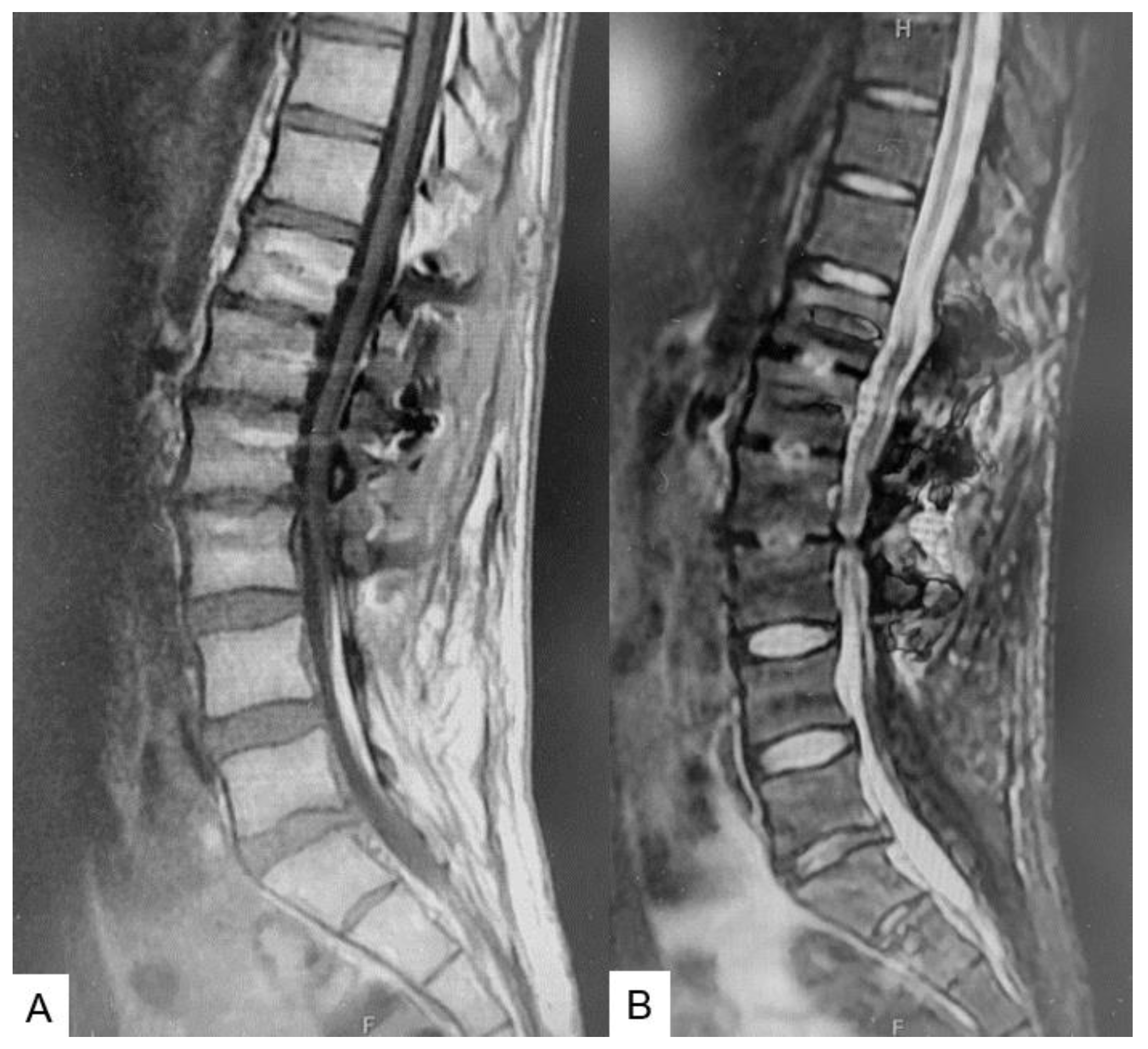
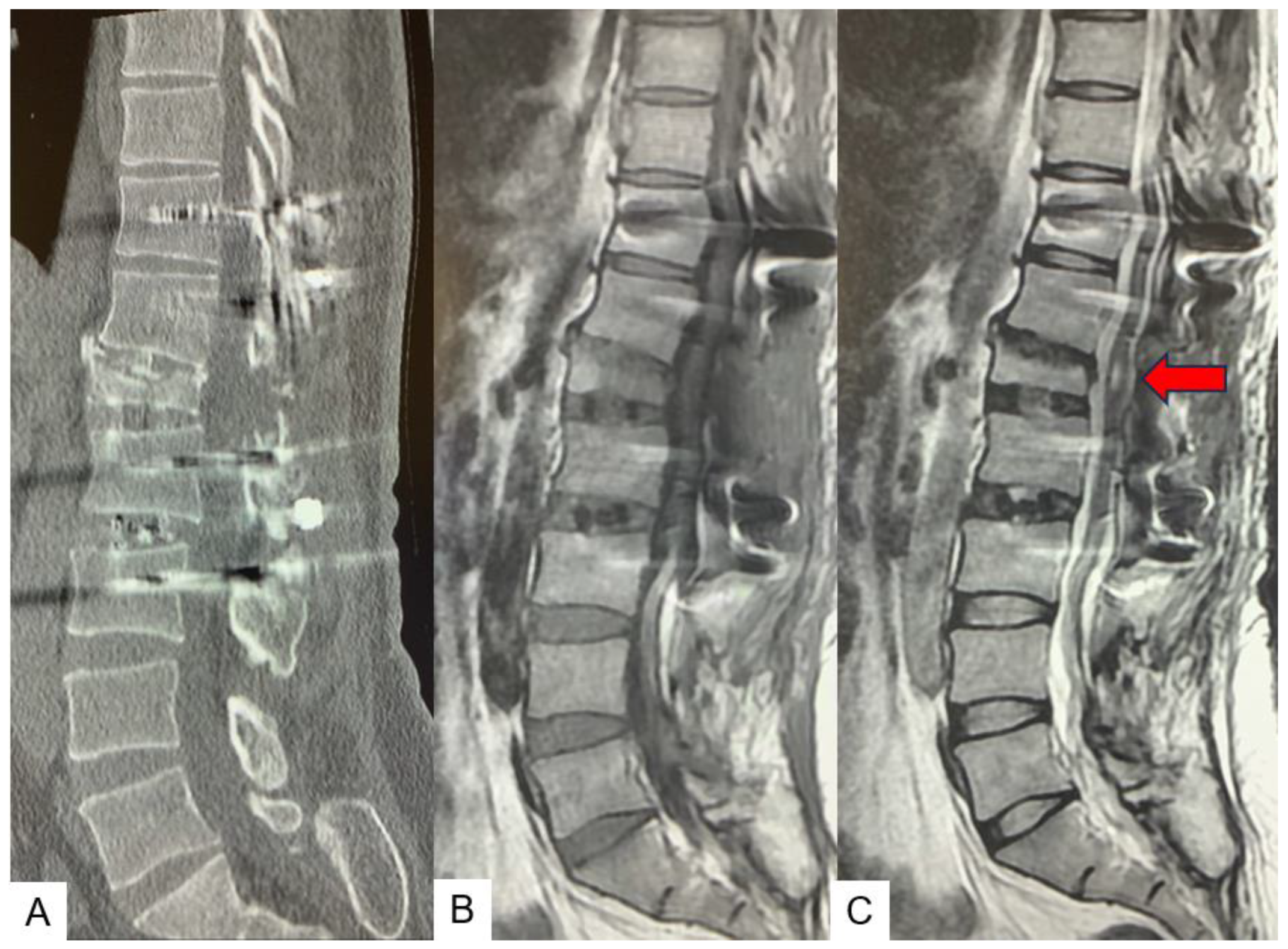
2.3. Preoperative imaging
2.4. Surgery
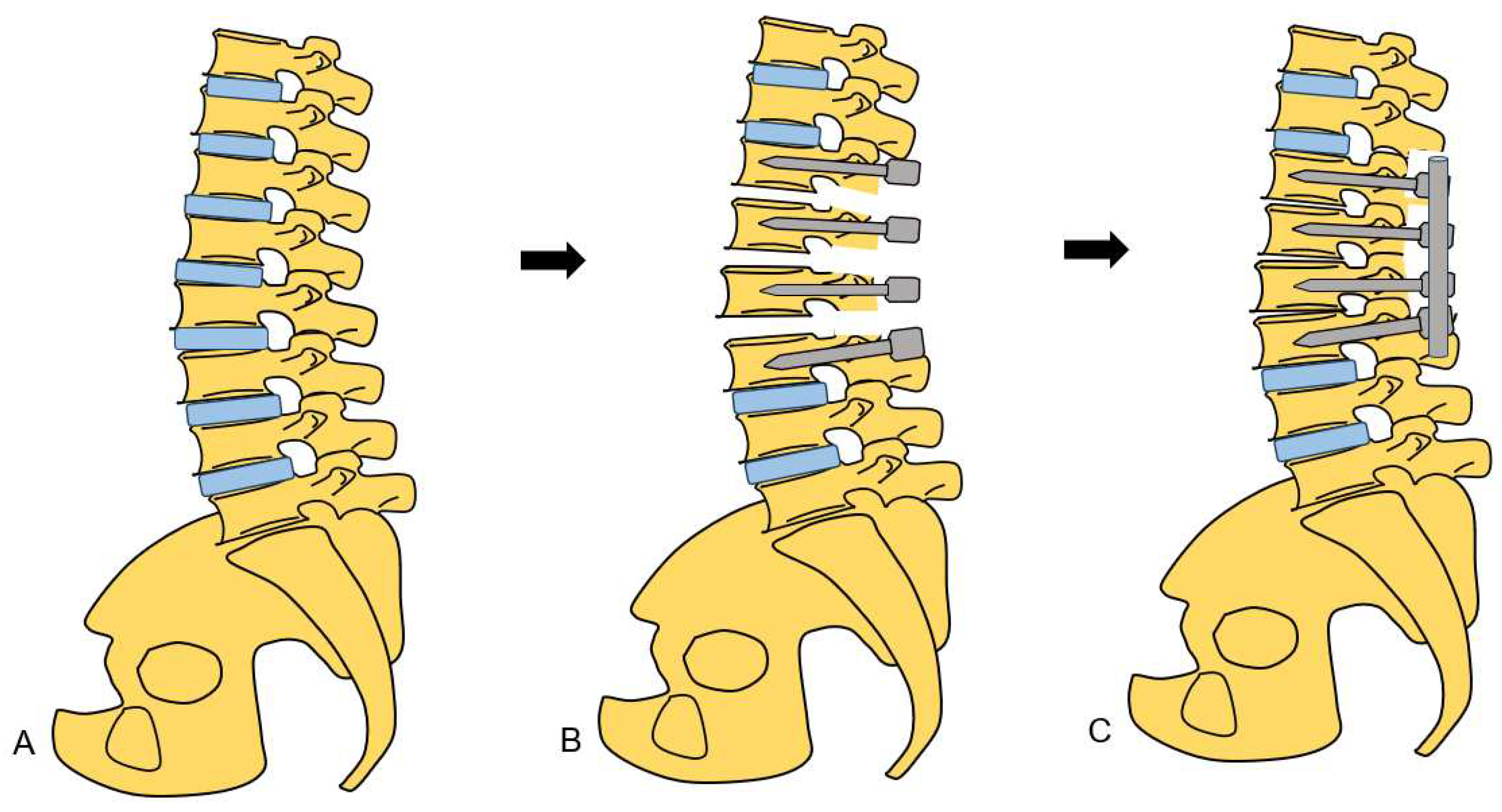
2.4.1. Anterior disectomy
2.4.2. Posterior osteotomy
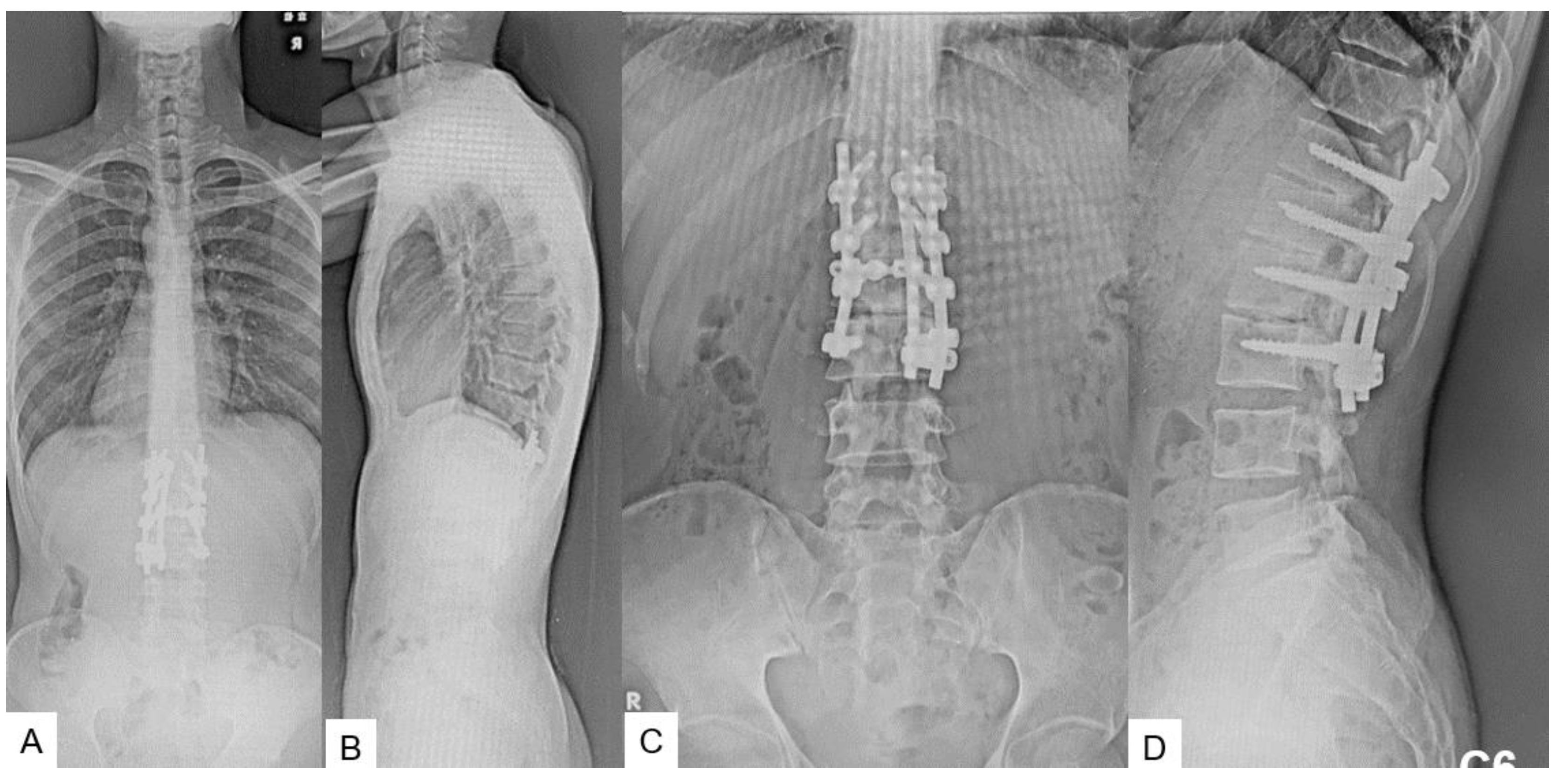
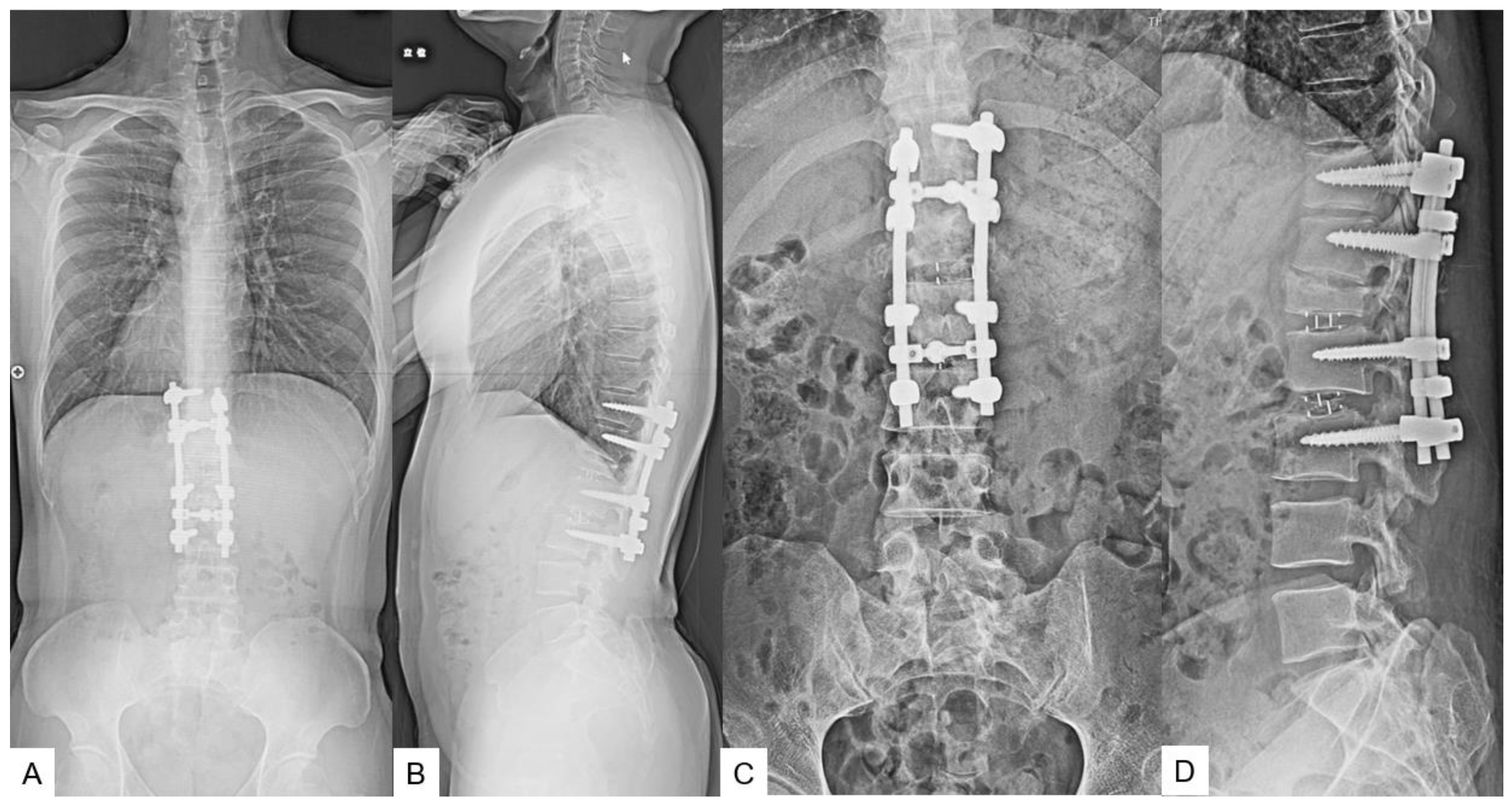
2.5. Postoperative imagings.
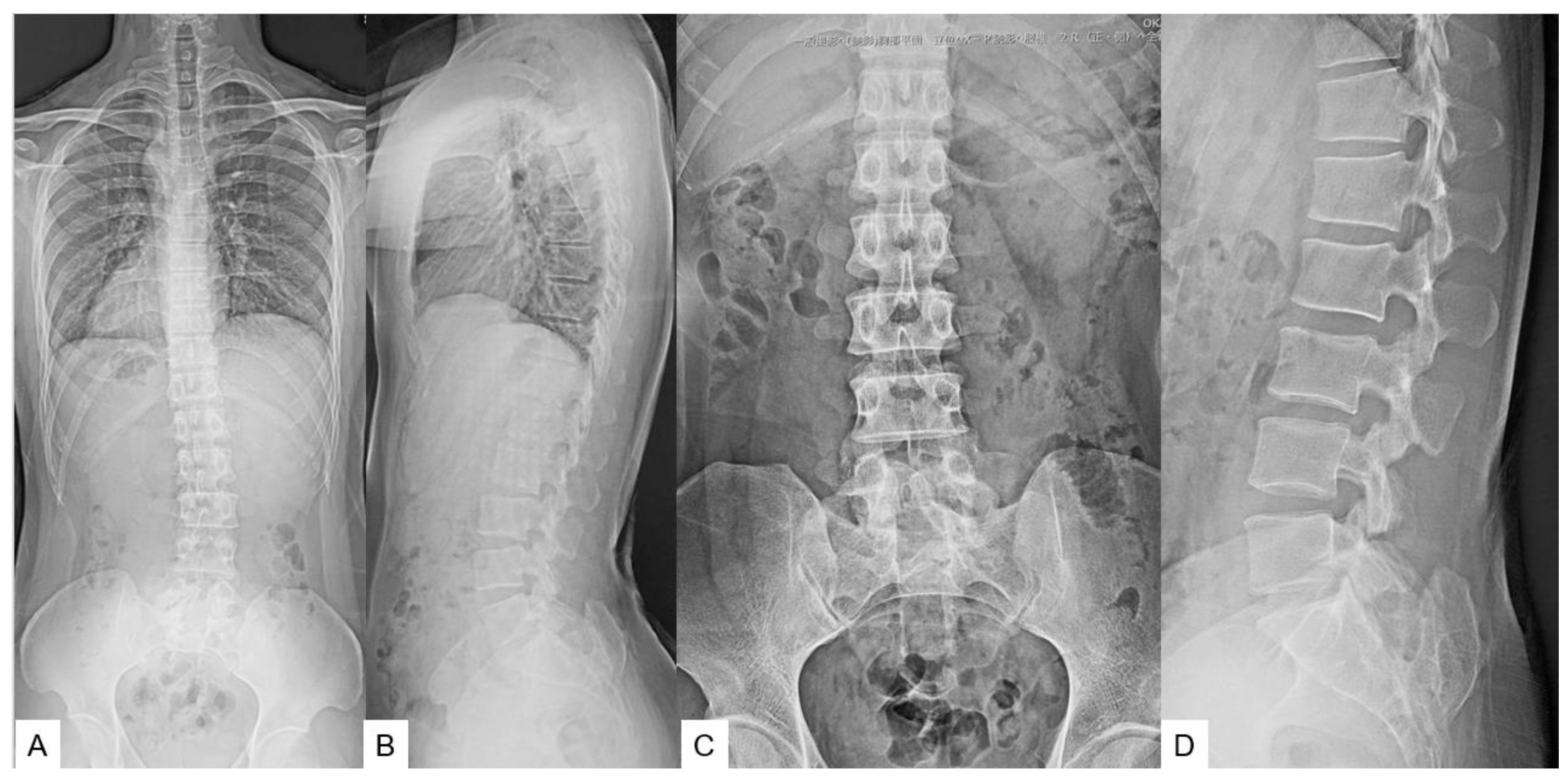
2.6. One year follow-up
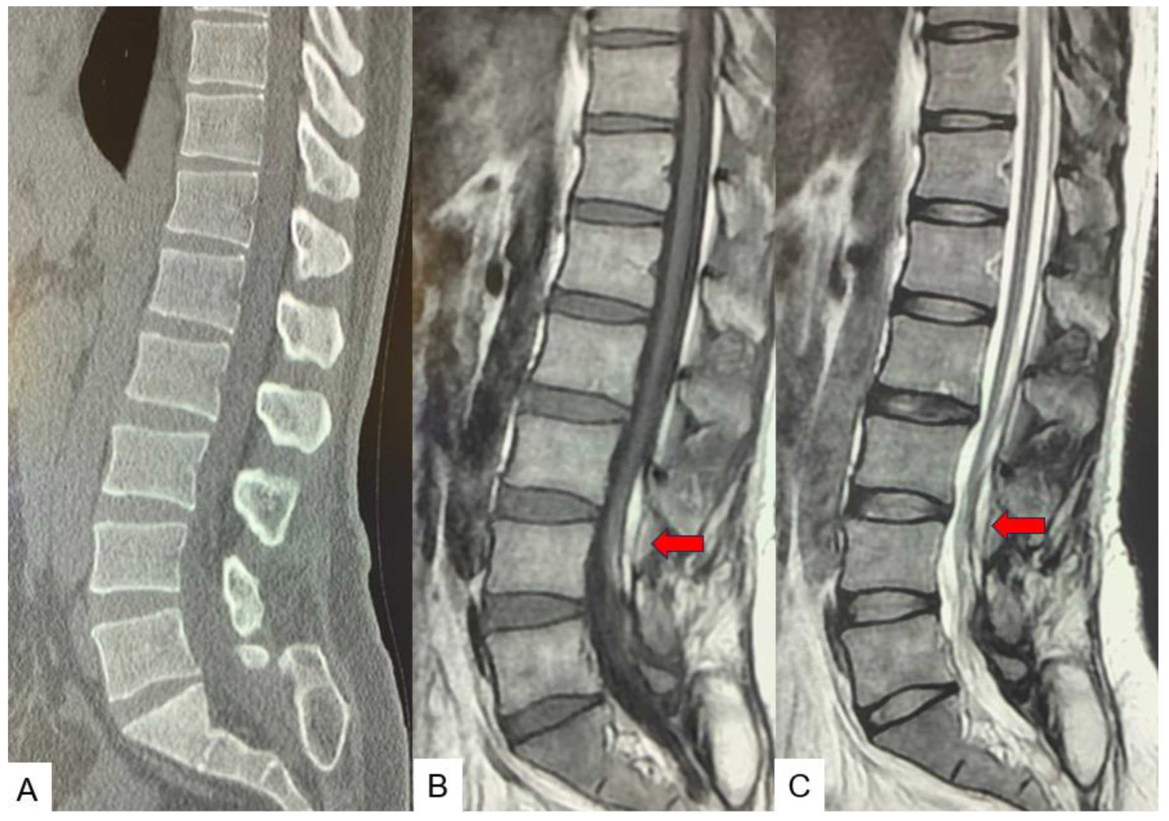
3. Case 2 33 years old male, tethered cord syndrome, conventional technique
4. Discussion
5. Conclusions
Author Contributions
Funding
Institutional Review Board Statement
Informed Consent Statement
Data Availability Statement
Acknowledgments
Conflicts of Interest
References
- Chapman PH: Congenital intraspinal lipomas: anatomic considerations and surgical treatment. Childs Brain 9:37–47, 1982. [CrossRef]
- Yamada S, Knerium DS, Mandybur GM, Schultz RL, Yamada BS: Pathophysiology of tethered cord syndrome and other complex factors. Neurol Res 26:722–726, 2004. [CrossRef]
- Pang D, Wilberger JE Jr: Tethered cord syndrome in adults. J Neurosurg 57:32–47, 1982. [CrossRef]
- Bui CJ, Tubbs RS, Oakes WJ: Tethered cord syndrome in children: a review. Neurosurg Focus 23(2):E2, 2007. [CrossRef]
- Hsieh PC, Stapleton CJ, Moldavskiy P, Koski TR, Ondra SL, Gokaslan ZL, Kuntz C. Posterior vertebral column subtraction osteotomy for the treatment of tethered cord syndrome: review of the literature and clinical outcomes of all cases reported to date. Neurosurg Focus. 2010 Jul;29(1):E6. [CrossRef]
- Archibeck MJ, Smith JT, Carroll KL, Davitt JS, Stevens PM: Surgical release of tethered spinal cord: survivorship analysis and orthopedic outcome. J Pediatr Orthop 17:773–776, 1997.
- Filler AG, Britton JA, Uttley D, Marsh HT: Adult postrepair myelomeningocoele and tethered cord syndrome: good surgical outcome after abrupt neurological decline. Br J Neurosurg 9:659–666, 1995. [CrossRef]
- Samuels R, McGirt MJ, Attenello FJ, Garcés Ambrossi GL, Singh N, Solakoglu C, et al: Incidence of symptomatic retethering after surgical management of pediatric tethered cord syndrome with or without duraplasty. Childs Nerv Syst 25:1085–1089, 2009. [CrossRef]
- Herman JM, McLone DG, Storrs BB, Dauser RC: Analysis of 153 patients with myelomeningocele or spinal lipoma reoperated upon for a tethered cord. Presentation, management and outcome. Pediatr Neurosurg 19:243–249, 1993. [CrossRef]
- Maher CO, Goumnerova L, Madsen JR, Proctor M, Scott RM: Outcome following multiple repeated spinal cord untethering operations. J Neurosurg 106 (6 Suppl):434–438, 2007. [CrossRef]
- Miyakoshi N, Abe E, Suzuki T, Kido T, Chiba M, Shimada Y. Spine-shortening vertebral osteotomy for tethered cord syndrome: report of three cases. Spine (Phila Pa 1976). 2009 Oct 15;34(22):E823-5. [CrossRef]
- Zhang C, Chang CC, Mummaneni PV, Yuan C, Dhall S, Jian F, Gupta N, Chou D. Spinal column shortening versus revision detethering for recurrent adult tethered cord syndrome: a preliminary comparison of perioperative and clinical outcomes. J Neurosurg Spine. 2020 Feb 7:1-7. [CrossRef]
- Auerbach JD, Lenke LG, Bridwell KH, Sehn JK, Milby AH, Bumpass D, Crawford CH 3rd, OʼShaughnessy BA, Buchowski JM, Chang MS, Zebala LP, Sides BA. Major complications and comparison between 3-column osteotomy techniques in 105 consecutive spinal deformity procedures. Spine (Phila Pa 1976). 2012 Jun 15;37(14):1198-210. [CrossRef]
- Garceau: George J. The filum terminale syndrome. The Journal of Bone & Joint Surgery 195335(3):p 711-716.
- Harold J Hoffman; E. Bruce Hendrick; Robin P Humphreys. The tethered spinal cord its protean manifestations, diagnosis and surgical correction. Child’s Brain 1976: 145-155. [CrossRef]
- Yamada S, Zinke DE, Sanders D. Pathophysiology of “tethered cord syndrome.” Vol. 54, J Neurosurg. 1981. [CrossRef]
- Yamada S, Knerium DS, Mandybur GM, Schultz RL, Yamada BS. Pathophysiology of tethered cord syndrome and other complex factors. Neurological Research. 2004, 722–726. [CrossRef]
- N. Muthukumar; B. Subramaniam; T. Gnanaseelan; R. Rathinam; A. Thiruthavadoss. Tethered cord syndrome in children with anorectal. J Neurosurg 2000, 92, 626–630. [CrossRef]
- J. Herman; D. McLone; B. Storrs; R. Dauser.Analysis of 153 patients with myelomeningocele or spinal lipoma reoperated upon for a tethered cord. Presentation, management and outcome. Pediatr Neurosurg 1993, 19, 243-249. [CrossRef]
- D E Warder; W J Oakes.Tethered cord syndrome and the conus in a normal position. Neurosurgery, 1993 Sep;33(3):374-378.
- O’Connor KP, Smitherman AD, Milton CK, Palejwala AH, Lu VM, Johnston SE, et al. Surgical Treatment of Tethered Cord Syndrome in Adults: A Systematic Review and Meta-Analysis. World Neurosurg. 2020, 1, 137, 221–241. [CrossRef]
- A G Filler ; J A Britton; D Uttley; H T Marsh. Adult postrepair myelomeningocoele and tethered cord syndrome good surgical outcome after abrupt neurological decline. Br J Neurosurg, 1995, 9(5), 659-666.
- Samuels R, McGirt MJ, Attenello FJ, Garcés Ambrossi GL, Singh N, Solakoglu C, et al. Incidence of symptomatic retethering after surgical management of pediatric tethered cord syndrome with or without duraplasty. Child’s Nervous System. 2009, 25(9), 1085–1089. [CrossRef]
- Morimoto K, Takemoto O, Wakayama A. Spinal lipomas in children - Surgical management and long-term follow-up. Pediatr Neurosurg. 2005, 41(2), 84–87. [CrossRef]
- Kokubun S, Ozawa H, Aizawa T, Ly NM, Tanaka Y. Spine-shortening osteotomy for patients with tethered cord syndrome caused by lipomyelomeningocele. J Neurosurg Spine. 2011, 15(1), 21–27. [CrossRef]
- Miyakoshi N, Abe E, Suzuki T, Kido T, Chiba M, Shimada Y. Spine-Shortening Vertebral Osteotomy for Tethered Cord Syndrome Report of Three Cases. SPINE , 34, 22, 823–825. [CrossRef]
- Auerbach JD, Lenke LG, Bridwell KH, Sehn JK, Milby AH, Bumpass D, et al. Major complications and comparison between 3-column osteotomy techniques in 105 consecutive spinal deformity procedures. Spine (Phila Pa 1976). 2012, 37(14),1198–210. [CrossRef]
- Masato Tanaka, Sameer Ruparel, Yoshiaki Oda, Yoshihiro Fujiwara, Sneha Shama, Koji Uotani, Shinya Arataki, Taro Yamauchi, Naveen Sake. C arm Free Simultaneous OLIF51 and Percutaneous Pedicle Screw Fixation in a Single Lateral Position. J Vis Exp, 2022, 16, 187-192. [CrossRef]
- Li B, Guo R, Jiang X, Wu J, Zhang D, Yang C, et al. Posterior wedge osteotomy assisted by O-arm navigation for treating ankylosing spondylitis with thoracolumbar fractures: An early clinical evaluation. Ann Palliat Med. 2021, 1, 10(6), 694–705. [CrossRef]
- D. Croci; S. Nguyen; S. Streitmatter; B. Sherrod; J. Hardy; K. Cole; A. Gamblin; E. Bisson; M Mazur; A. Dailey. O Arm Accuracy and Radiation Exposure in Adult Deformity Surgery. World Neurosurg. 2023, 171, 440-446. [CrossRef]


Disclaimer/Publisher’s Note: The statements, opinions and data contained in all publications are solely those of the individual author(s) and contributor(s) and not of MDPI and/or the editor(s). MDPI and/or the editor(s) disclaim responsibility for any injury to people or property resulting from any ideas, methods, instructions or products referred to in the content. |
© 2023 by the authors. Licensee MDPI, Basel, Switzerland. This article is an open access article distributed under the terms and conditions of the Creative Commons Attribution (CC BY) license (http://creativecommons.org/licenses/by/4.0/).


