1. Introduction
Urban underground pipelines serve as vital components of cities, facilitating the transportation of crucial resources such as water and natural gas. They play a pivotal role in supporting daily life and industrial production, functioning as the lifelines of cities and contributing significantly to smart city development.However, the presence of deformations in these pipelines can pose safety hazards, leading to collapses and economic losses. These pipelines typically concealed from view, which allow internal deformations to accumulate over time. Consequently, it is widely acknowledged that conducting regular inspections during both the construction and operational phases of underground pipelines is crucial for maintaining and repairing existing and potential deformations. These inspections are essential for ensuring the reliability of underground pipelines and mitigating risks by identifying and addressing issues in a timely manner. Underground pipelines are susceptible to damage from various factors, including working conditions and the surrounding environment. However, the intricate nature of pipeline infrastructure poses challenges in locating and detecting common deformations. Traditional pipeline inspections have heavily relied on manual labor, which is both labor-intensive and hazardous. Recent technological advancements have introduced robots as alternatives to human workers, allowing them to enter confined spaces and capture videos to avoid potential risks.
Existing pipeline inspection techniques can generally be categorized into visual inspection and sensor-based detection [
1]. Visual inspection involves manual maintenance conducted by personnel who directly inspect the pipeline using techniques like mirrors and diving. However, direct visual inspection comes with disadvantages such as high workload, low accuracy, and the potential for missed defects due to its reliance on human labor. Moreover, ensuring the safety of inspection personnel can be challenging and is dependent on the pipeline’s size and working environment. In contrast, sensor-based detection methods utilize specialized equipment designed for specific pipeline conditions and sizes, reducing the dependence on human resources and mitigating potential risks. Sensor-based pipeline inspection platforms primarily consist of robots equipped with specialized sensor devices that enter the pipeline to perform inspections and gather information about its operational conditions. Depending on the type of sensor equipment used, various detection technologies are available, including infrared thermography systems [
2], ground-penetrating radar systems [
3], ultrasound detection systems [
4] and magnetic leakage detection technology [
5]. However, these detection methods often focus on specific defect types and may lack universal applicability.
With the rapid advancement of imaging sensors and improvements in machine computing capabilities, Closed-Circuit Television (CCTV) inspection [
6] has become a mainstream technology for internal pipeline inspections. This technique involves deploying robots equipped with cameras into the pipeline to perform video-based inspections [
7]. The captured images are uploaded to a central unit, where they are examined and interpreted by trained engineers. Compared to sensor-based detection methods, CCTV inspection offers advantages like lower cost and simplified operation. However, as the total length of urban underground pipeline networks continues to increase, inspection methods that rely on manually traversing large amounts of video footage become time-consuming and inefficient. This inefficiency leads to inadequate inspection and increased risk of human error. As a result, current research on CCTV technology focuses on transitioning from human-dependent pipeline condition assessment to automated machine recognition [
8,
9]. For instance, Dang
et al. [
10] proposed a multi-framework ensemble detection model that extracts precise defect information from key frames of CCTV videos by leveraging different frameworks’ strengths. Cheng and Wang [
11] used the Faster R-CNN technique to identify defects in sewage pipelines and investigated the impact of network hyper-parameters on recognition accuracy. Jiao
et al. [
12] introduced a steerable autoencoder-based framework for anomaly detection in CCTV frames. Yin
et al. [
13] applied the YOLOv3 network with a simulated annealing algorithm to achieve real-time defect detection in sewage pipelines. Ma
et al. [
14] proposed a real-time processing and segmentation framework for automatic deblurring of pipeline defect images using a GAN network. Despite progress in these recognition techniques, the limitations of two-dimensional imaging technology hinder accurate assessments of crucial parameters such as changes in pipeline wall thickness and deformation severity, limiting comprehensive pipeline structure analysis.
To address these challenges, three-dimensional (3D) laser scanning emerges as a more feasible solution. This technology utilizes laser scanners to conduct internal pipeline scans, capturing point cloud data and offering significant advantages. Firstly, laser scanning delivers high-speed data acquisition, allowing for the rapid collection of large quantities of highly accurate 3D point cloud data. This capability facilitates the precise detection and reconstruction of internal pipeline conditions, reflecting aspects such as cracks, corrosion, and deformations, especially in confined spaces. Secondly, laser scanners exhibit robust directional capabilities, making them less sensitive to ambient lighting conditions. This enables reliable measurements even in larger objects or on-site scenarios, making laser scanning a suitable solution for internal pipeline inspection. Researchers have proposed various methods to enhance the application of laser point cloud imaging technology in pipeline inspection. To overcome the limitation of insufficient accuracy in pure radar scanning, Li
et al. [
15] proposed a method that combines radar information with camera video information, thereby improving the accuracy and completeness of model reconstruction. Cheng
et al. [
16] introduced a prior-based pipeline reconstruction method that reduces the complexity of general pipeline reconstruction problems by integrating part detection and model fitting, using convolutional networks to detect pipeline components and fit them into the original point cloud data. Haugsten Hansen [
17] improved upon Vetle Sillerud’s model and proposed a 3D reconstruction method that combines radar and IMU data, using machine learning to reconstruct scenes with precise dimensional information. Tan
et al. [
18] proposed a method for 3D wire-frame reconstruction from point clouds, addressing the challenges of sparsity, irregularity, and noise through learning-based prediction, pruning modules, and a particle swarm optimization algorithm. However, despite these advancements, the mentioned methods lack the capability for quantitative analysis of internal geometric deformations. To overcome this limitation, this paper proposes a method for quantitatively detecting internal spatial deformations in underground pipelines using laser point cloud data. This approach combines traditional pipeline robots for in-depth inspections with high-precision radar to capture more information about the inner walls of the pipeline, thereby enhancing the accuracy and precision of deformation assessment. Additionally, a grid-based algorithm is employed to extract the contour of the inner pipeline walls, facilitating the determination of the section’s loss area and enabling the detection and localization of pipeline damage.
The remainder of this paper is organized as follows.
Section 2 introduces the hardware structure design of the overall experimental system. In
Section 3, the framework of the proposed method for pipeline internal wall scan based on high-density point cloud data is described. In
Section 4, the detection rate and detection accuracy of the proposed method are analyzed for pipelines with different levels of blockage. Finally,
Section 5 concludes the paper and discusses future work.
2. Hardware Design
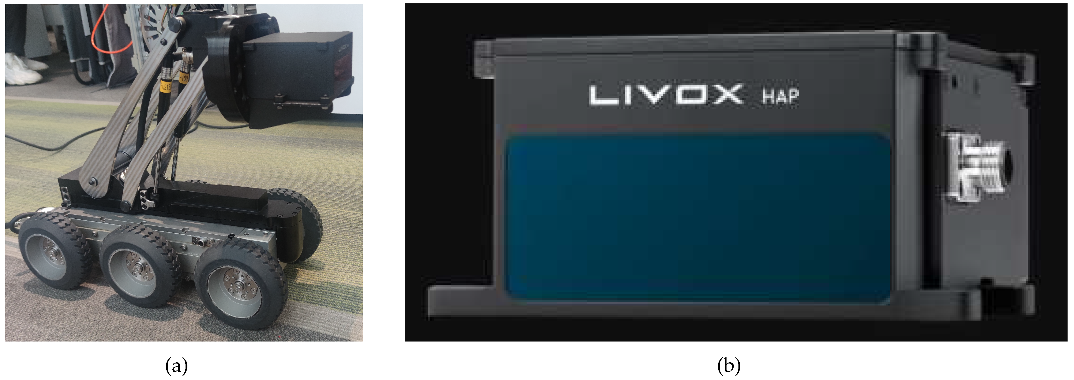
The detection system comprises two main components: the execution mechanism and the sensing and detection mechanism. The execution mechanism is represented by a four-wheel-drive smart car, as illustrated in
Figure 1a. The sensing and detection module, integrated into the mobile platform, comprises an Inertial Measurement Unit (IMU) module and a Light Detection and Ranging (LiDAR) module. The IMU module is incorporated into the system to precisely measure and track the pose of the LiDAR. As depicted in
Figure 1b, the LiDAR system employs the LIVOX HAP, leveraging high-speed non-repetitive scanning technology and multi-line packaged lasers.
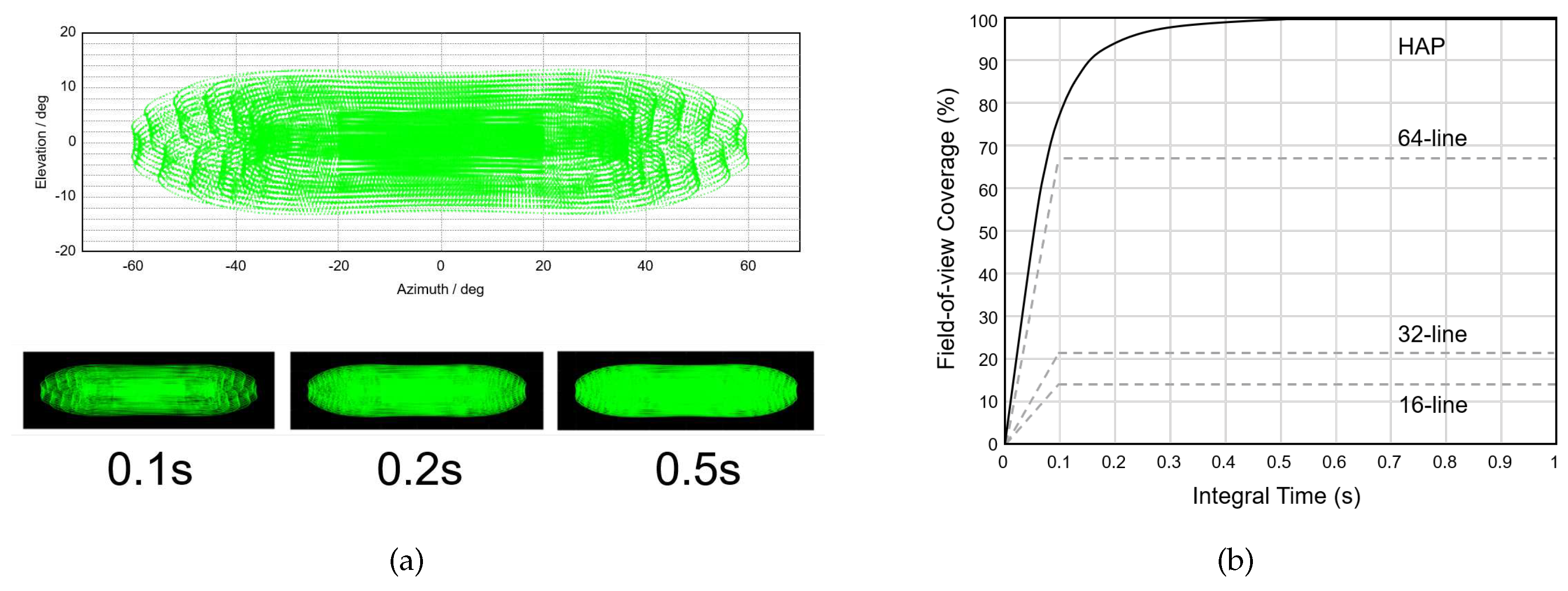
Figure 2a displays the typical point cloud distribution at 0.1s integration time and the field-of-view coverage of the HAP at different integration times. In this representation, the central area exhibits a higher point density, with an average scanning interval of approximately 0.2 degrees, while the point density decreases towards the ends, with an average scanning interval of approximately 0.3 degrees. Additionally, it is noteworthy that a longer integration time has a subtle effect on the field-of-view range but enhances the coverage rate. This enhancement allows for capturing finer details within the field of view. In
Figure 2b, the field-of-view coverage of the HAP is compared with 16-line, 32-line, and 64-line LiDARs at different integration times. Remarkably, the HAP achieves a field-of-view coverage of approximately 80% when the integration time is less than 0.1 seconds, surpassing that of a typical 64-line mechanically rotating LiDAR. As the integration time increases, more details are captured, and the point cloud coverage rate improves to over 99%. These results underscore the outstanding coverage and resolution capabilities of the HAP, making it highly suitable for 3D scanning and modeling in underground pipeline scenarios.
3. Related Work
The laser scanning system enables the acquisition of a large volume of high-precision 3D point cloud data from various perspectives, facilitating the efficient reconstruction of the 3D pipeline network model. The workflow for quantitative detection of internal deformations in pipelines based on laser scanning, as illustrated in
Figure 3, involves the following key steps.
Firstly, real-time or recorded point cloud information is obtained through point cloud reading. Multiple point clouds from various time frames are then registered and combined to form a comprehensive dataset representing the internal space of the pipeline. Based on the variations in the coordinate information of the point cloud, the direction of the pipeline is determined. Using this information, the point cloud is cropped and segmented along the pipeline direction at fixed intervals. Subsequently, the cropped 3D point cloud information is projected onto a 2D cross-section. Through the application of filtering and downsampling techniques, the contour information of the local cross-section’s point cloud is extracted. Once the contour point cloud information is obtained, it undergoes further processing to generate an ordered point cloud, and interpolation techniques are applied to enhance the spatial distribution density of the point cloud. Finally, the interpolated pipeline contour is used to calculate the area of the detected deformation. This process provides specific numerical information for deformation evaluation and offers robust data support for quantitative deformation detection.
3.1. Point Cloud Data Acquisition
Point cloud data is a dataset that contains rich information in the Cartesian coordinate system, including three-dimensional coordinates (X, Y, Z), color, classification values, intensity values, and timestamps. By scanning the internal structure of the pipeline, spatial point cloud data from different positions within the pipeline can be obtained, forming the foundation for subsequent analysis. To assess the effectiveness and accuracy of the proposed method, an experimental pipeline blockage model is created. This model involves placing obstructions of varying volumes inside the pipeline to simulate different blockage scenarios. This setup allows for the evaluation of the proposed method’s performance in detecting and quantifying internal deformation extent under varying blockage conditions. The intelligent vehicle, equipped with laser-based 3D scanning capabilities, is then deployed into the pipeline to capture the point cloud information. To enhance the accuracy of internal reconstruction, point cloud data from different time frames are overlapped and combined to achieve more precise internal reconstruction results.
3.2. Point Cloud Preprocessing
The point cloud generated from laser scanning typically contains a substantial volume of data and is often accompanied by noise, especially when scanning complex objects like pipelines. Additionally, the complexity of the pipeline environment can result in missing data points, posing challenges for the reconstruction of the pipeline network model. To achieve accurate reconstruction of the pipeline network model, preprocessing operations are applied to the point cloud data. These preprocessing steps include point cloud filtering, registration, segmentation, and projection. Filtering techniques are employed to remove noise and outliers from the point cloud data, thereby enhancing the quality and reliability of the reconstructed model. Point cloud registration involves aligning multiple point clouds acquired from different viewpoints or time frames to create a unified and complete representation of the pipeline’s internal structure. Point cloud segmentation and projection entail dividing the point cloud into meaningful regions based on geometric properties or clustering algorithms. This process enables further analysis and processing of specific pipeline components. Projection techniques are then applied to project the segmented point cloud onto a two-dimensional representation, facilitating subsequent analysis and visualization. These preprocessing steps optimize the point cloud data while preserving the geometric characteristics of the pipeline, leading to a more detailed and comprehensive representation of the pipeline network.
3.2.1. Point Cloud Denoising
During the process of laser scanning, the received point cloud signals can be influenced by various factors, such as the surface characteristics of the pipeline inner wall, scanning environment, and system limitations. Consequently, the acquired point cloud data often contains noise and outliers, necessitating denoising operations to enhance the effectiveness of subsequent point cloud processing. Point cloud denoising typically involves several methods, including outlier removal, normal-based filtering, and voxel-based filtering. These denoising techniques effectively eliminate or smooth out the noise and outliers present in the point cloud, thereby improving the accuracy and effectiveness of subsequent point cloud processing.
3.2.2. Point Cloud Registration
Point cloud registration is the process of aligning multiple point clouds to achieve a more accurate 3D model in a common coordinate system. Various methods can be employed for point cloud registration, including target-based registration, feature-based registration, measurement-based registration, and hybrid registration. Among these methods, the Iterative Closest Point (ICP) algorithm is a widely used automatic point cloud registration method. The ICP algorithm aims to find correspondences between points in the source and target point clouds and iteratively optimizes the rotation and translation parameters using the least squares method. In this work, the ICP algorithm is primarily used for point cloud registration, following these principles:
Assuming the presence of two sets of unregistered point cloud data, denoted as
and
. Here
X represents the source point cloud,
Y represents the target point cloud, and
denotes the point in the target point cloud
Y that is closest to
in the source point cloud. The objective is to find an optimal rigid transformation matrix, typically represented by an affine transformation matrix
, which can accurately align the source point cloud
X with the target point cloud
Y. This matrix satisfies the equation:
Here,
R represents the rotation matrix and
t represents the translation matrix. The algorithm utilizes the least squares method to quantify the closeness between the two point clouds and defines an error function as follows:
Based on Equation
2, the ICP problem is transformed into finding the optimal
R and
t that minimize
. To solve for the optimal rotation matrix
R and translation matrix
t, the centroid of each point cloud is calculated using Eq.
3, and then obtains the demeaned point clouds using Eq.
4, where
.
The demeaned point clouds sets as
and
. The optimal rotation matrix
R now can be found by minimizing the error function:
To compute
, the algorithm defines the matrix
, which is a
matrix. Performing the Singular Value Decomposition (SVD) of
W yields:
When
W is full rank, there exists a unique combination of
U and
V, which allows to derive the optimal rotation matrix
R and the translation vector
t:
Hence, the optimal solution for
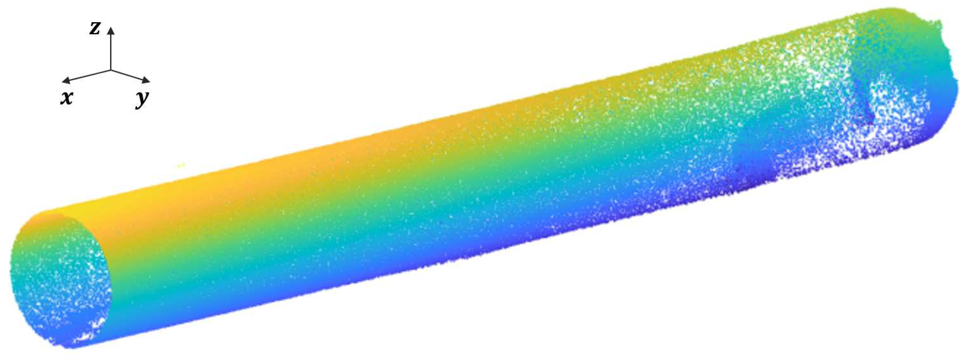
is obtained. Using this approach, all 34 remaining point cloud sets are registered. The resulting registered point cloud data is depicted in
Figure 4.
3.2.3. Point Cloud Segmentation and Projection
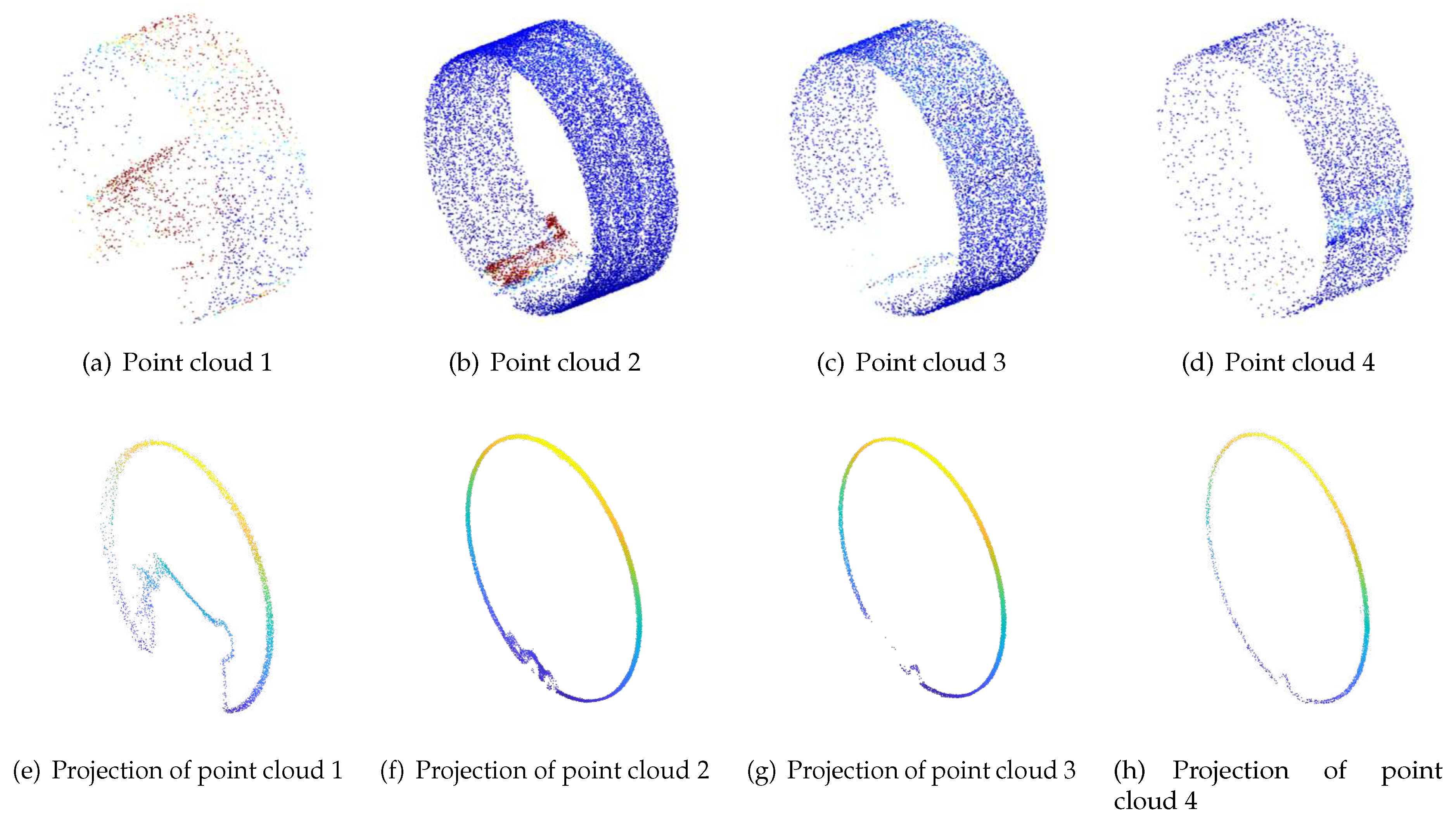
The recognition of the pipeline’s orientation is primarily achieved by comparing the coordinate values of the point cloud in the X, Y, and Z directions. Since the pipeline has a cylindrical structure, the variation range of the point cloud data in the Y and Z coordinates is relatively small. Based on the coordinate system of the laser scanner, the main orientation of pipelines can be determined by analyzing the coordinate values along the X-axis. Therefore, the clipping operation on the point cloud data is mainly performed along the X-axis. Taking into account the structural characteristics of the pipeline and the limitations of computational resources, the dataset is clipped at an interval of 0.1 m along the X-axis. The clipped point cloud is then projected onto the YZ-plane, forming a dense distribution of 2D point clouds, as shown in
Figure 5. To reduce the data size and improve computational efficiency and modeling speed without compromising important geometric features, downsampling is applied to the projected point cloud. Common point cloud downsampling algorithms include spatial segmentation-based methods and curvature-based methods. In this experiment, the point cloud is downsampled with an interval of 0.2m.
3.3. Internal profile Extraction and Quantitative Detection
Based on the point cloud preprocessing discussed in
Section 3.2, it is essential to evaluate the blockage ratio information of the pipeline cross-sectional contour point cloud. Various methods have been proposed for point cloud boundary extraction, including latitude-longitude scanning, grid partitioning, normal estimation, and alpha shapes algorithm. Considering the specific characteristics of each algorithm, the grid partitioning method is adopted in this experiment to detect the boundary of the pipeline point cloud. Specifically, the grid partitioning method includes the following three steps.
3.3.1. Grid partitioning and hollow cell filling
The widely used grid partitioning method is the uniform gridding approach. Firstly, the acquired 3D data point cloud set
is mapped to a 2D plane by applying coordinate transformation, forming a point cloud set
within the plane. Here,
and
. After obtaining the mathematical representation of the point set, all points are traversed to determine the maximum and minimum values of
x and
y, denoted as
,
,
and
, respectively. This establishes the minimum bounding box for the point set. Based on this, the grid size
L can be calculated as:
Correspondingly, the number of grids in the
x and
y directions, denoted as
and
, can be calculated as:
The data points are assigned to the corresponding grid cell , establishing a mapping relationship between them. Here, and . Subsequently, the grid cells can be classified into two categories based on the presence of data points: "occupied grids" that contain data points and "empty grids" that lack data points. However, due to the non-uniform distribution of point clouds in the plane, the use of small grid sizes can lead to the occurrence of isolated "empty grids", in which case the neighbouring grids may erroneously be classified as boundary grids. To address this issue, a filling operation is employed to populate these "empty grids", thereby mitigating the risk of misidentifying certain data points as boundary points. Bilinear interpolation is commonly used for this purpose.
3.3.2. Boundary Point Cloud Grid Identification
In the grid structure, the general principle for identifying boundary point cloud grids involves assessing the quantity of "empty grids" among the neighboring grids, which is determined by the boundary property. Specifically, for each "occupied grid" within the structure, the number of "empty grids" among its eight adjacent grids is evaluated. A grid is classified as a boundary grid if it has more than one empty neighbor, while grids without such neighbors are not considered as boundaries. The identification of boundary grids facilitates a coarse approximation of the overall shape of the point cloud contours, distinguishing them from "empty grids" that lack boundary characteristics. This principle serves as a basis for identifying boundary grids and extracting pertinent information regarding the boundaries of the point cloud.
3.3.3. Boundary Extraction
The extraction of boundary lines involves refining the identified boundary point cloud grids since they only provide an approximate shape of the point cloud contours, which does not meet the required accuracy in engineering applications. Subsequently, the task involves extracting the boundary points from each boundary grid and connecting them in a sequential manner to establish the initial boundary lines. The distribution characteristics of the neighboring points surrounding the boundary points are critical in this process. The neighboring points of boundary points tend to concentrate on one side of the boundary rather than being uniformly distributed around a particular point. This non-uniform distribution pattern is influenced by the contour shape represented by the boundary points. For instance, in point cloud data representing pipelines, the boundary points typically correspond to the edges of the pipes, while the neighboring points around these boundary points are situated within the interior of the pipes. Due to the inherent geometric shape of the pipes, the distribution of neighboring points around the boundary points exhibits a noticeable concentration in the edge region compared to the interior, thus displaying a non-uniform distribution pattern. Based on this non-uniform distribution of point clouds, an algorithm is employed to extract the boundary points through utilizing the standard deviation of angles to measure the uniformity of point cloud distribution. The algorithm follows these steps:
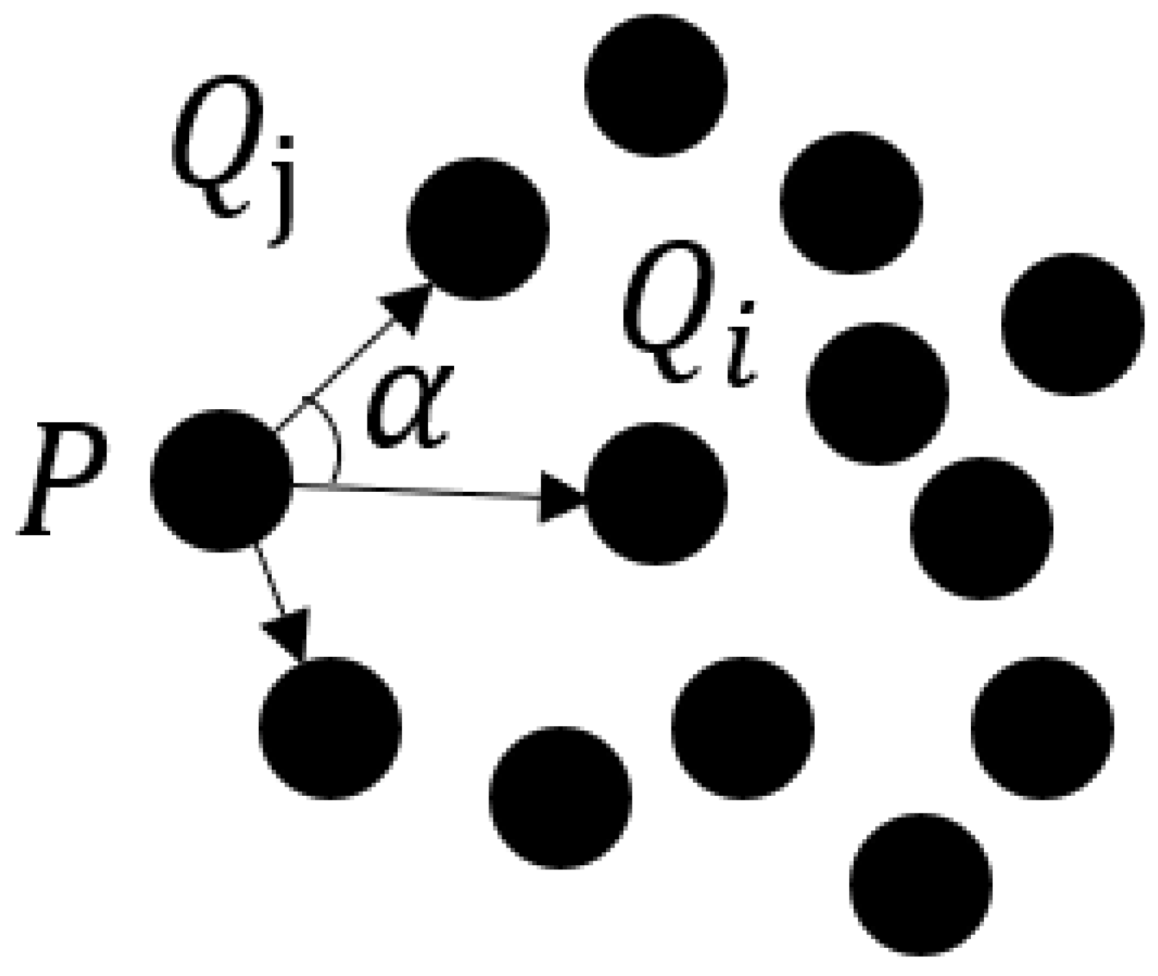
The k-nearest neighbors of a candidate point and the angles between the candidate point and each neighbors, denoted as
P and
, are searched and computed respectively. The angle
is defined as shown in
Figure 6. Let
represent the vector between the candidate point
P and the closest point
, and let
represent the vectors between
P and the remaining points, where
. The angles
between
and
are calculated to obtain a sequence of angles
.
The k-nearest neighbors are sorted in ascending order based on the sequence of angles to obtain a sorted sequence of angles .
-
The standard deviations
S of the sorted sequence of angles are calculated. Points that exceeds a certain threshold value for
S are identified as boundary feature points. To calculate the angle standard deviation, the angular difference
D of
is defined as:
Then, the corresponding standard deviation
S for the sequence of angular differences
is given by:
where
is denoted as:
If the standard deviation S exceeds the predefined threshold, the point is inferred to have an uneven distribution of its k-nearest neighbors and is thus classified as a boundary point. Conversely, if the standard deviation S is less than or equal to the specified threshold, the point is considered a non-boundary point. The threshold can be adjusted based on the complexity of the point cloud data boundaries. This process results in the generation of an unordered set of boundary feature points.
To sort the unordered set of boundary feature points, a k-d tree-based nearest neighbor search algorithm is employed. This method utilizes the k-d tree structure to search nearest neighbor within the point cloud, thereby identifying the boundary feature points and sorting them based on their proximity to each other. By connecting the sorted point sequence, the boundary lines of the point cloud can be obtained. To further enhance the smoothness and continuity of the boundary lines, a smoothing process is applied to the initial boundary lines, which sketches in the final boundary of the point cloud.
Based on the grid-based method described above, the identification and extraction of the outer contour on the projected plane of the pipeline can be achieved. This process lays the foundation for subsequent experimental analysis.
4. Experimental Result Analysis
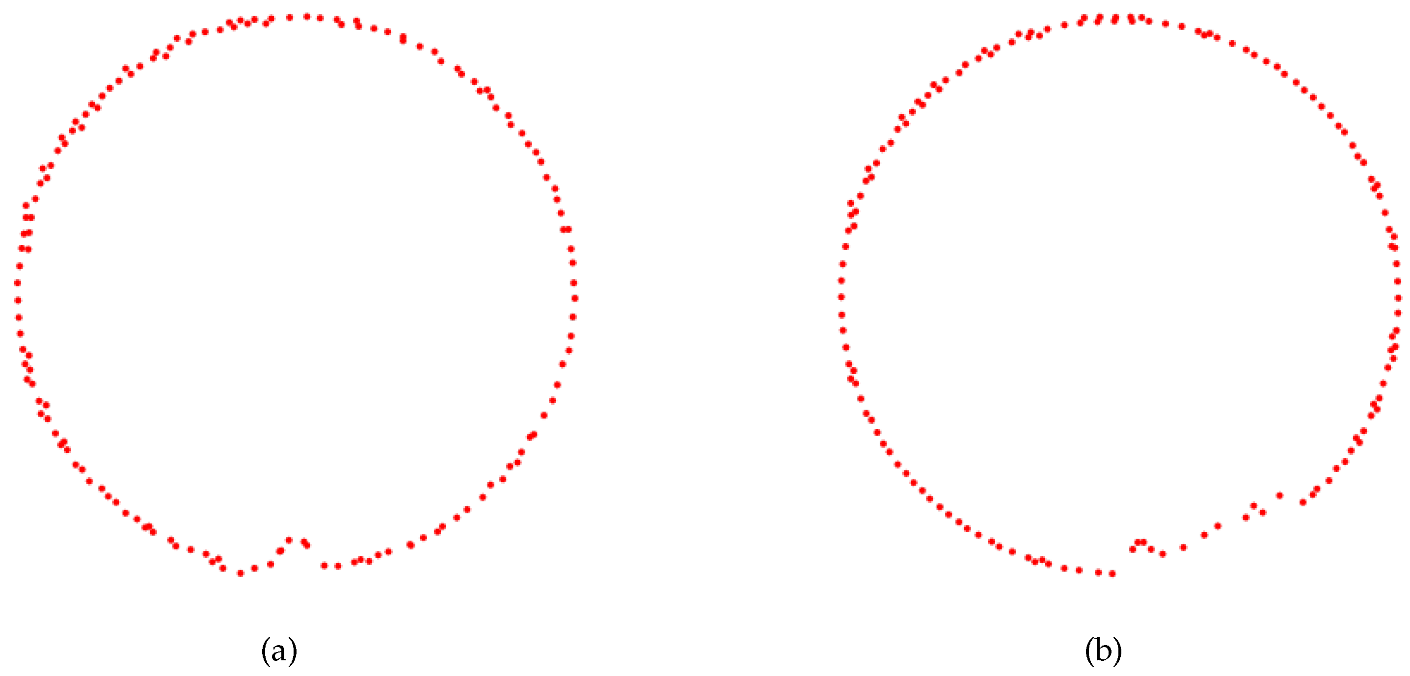
Figure 7 illustrates contour diagrams of two different point clouds subjected to projection downsampling. These processed point clouds exhibit clear pipeline contour lines, which indicates a regular cylindrical shape of the pipelines under the situation of no deformation or sedimentation. To accurately calculate the cross-sectional area enclosed by the point cloud boundary, interpolation processing is employed to improve the accuracy of the contour area calculation.
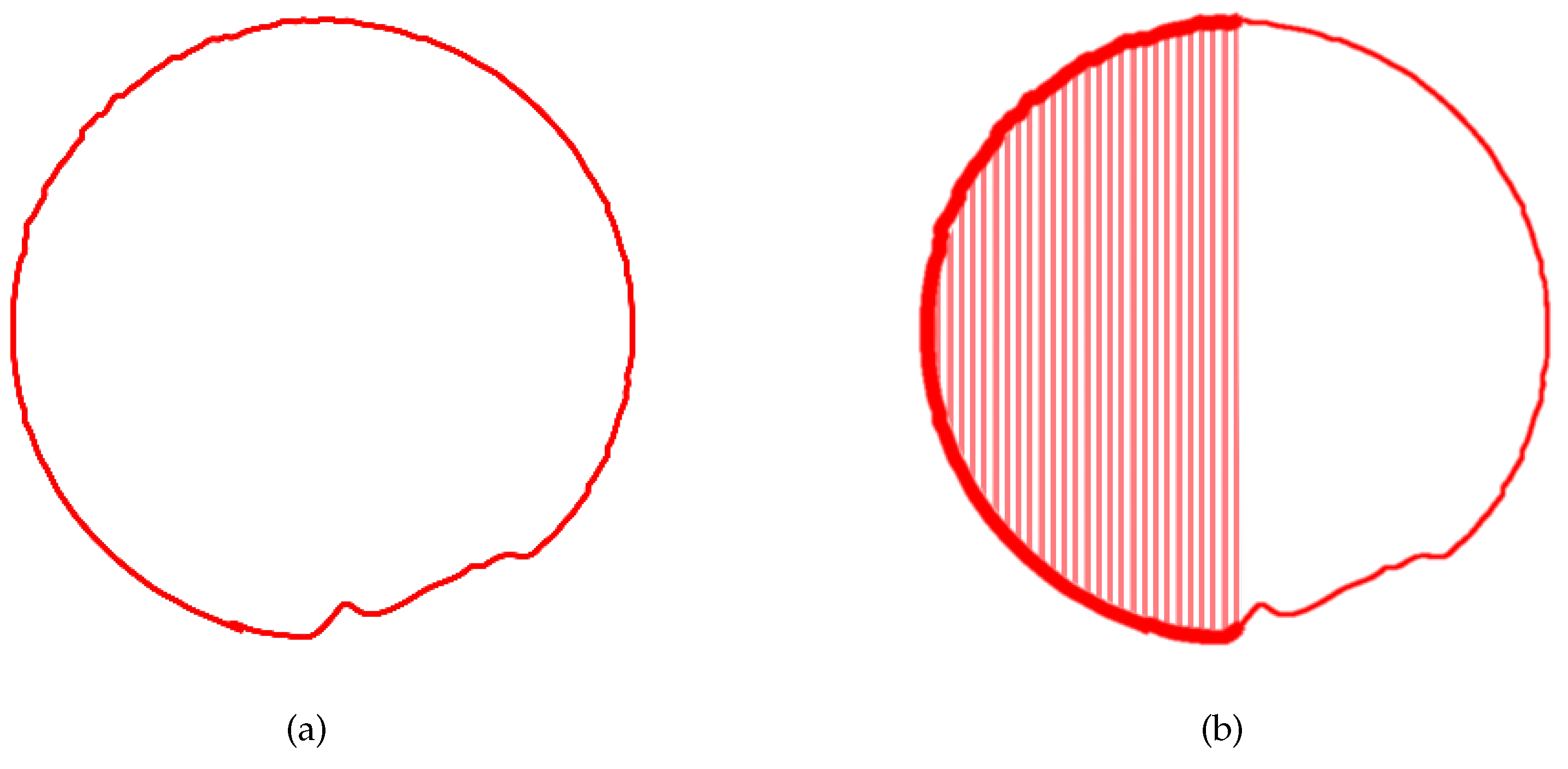
Figure 8a demonstrates the point cloud contour diagram after ordering and interpolation processing. Furthermore, by integrating the ellipticity or regular circular area of each circular section, as shown in
Figure 8b, the computed area can be compared with the known cross-sectional area of the pipeline. This facilitates the assessment of pipe deformation and sedimentation, thereby enabling the detection and analysis of the internal space of the pipeline.
Table 1 presents the comparison between the computed blockage ratio, obtained from the pipeline contour derived from the scanned point cloud, and the original pipe sectional area, which is denoted as 0.1963
. By comparing the computed blockage ratio with the original situation, the results provide valuable insights into the effectiveness of the proposed method. It is observed that the computed blockage ratio aligns closely with the actual blockage ratio, which indicates ability of the approach to accurately assess the degree of blockage within the pipeline. This indicates that the method has high reliability and effectiveness in detecting and analyzing the internal space of the pipeline. It enables quick and accurate assessment of pipeline blockage based on point cloud contour data, which provides important reference for pipeline maintenance and repair.
5. Conclusion and discussion
This study introduces a quantitative method for detecting internal deformations in underground pipelines using laser point cloud data. The proposed approach involves constructing a 3D scanning system for pipelines based on laser radar, enabling the objective and accurate detection of internal deformations within underground pipelines and the quantitative assessment of blockage ratios. The key steps of the method encompass determining the pipeline’s direction, clipping point cloud data, performing plane projection and downsampling, detecting point cloud contours, and transforming and interpolating point cloud data. In contrast to traditional Closed-Circuit Television (CCTV) inspection methods, this approach leverages the high-precision point cloud data generated by laser radar’s 3D scanning technology. By meticulously processing and analyzing this point cloud data, the method addresses issues related to subjectivity and limited accuracy in the detection process. It facilitates the precise identification of internal pipeline deformations and the calculation of blockage ratio data, offering a scientific foundation for pipeline assessment. The research findings underscore the high feasibility and accuracy of the quantitative detection method based on laser point cloud data for internal pipeline deformations. These results provide crucial technical support for relevant maintenance and repair efforts. Future research endeavors could concentrate on enhancing the practical application of this method by integrating machine learning and image processing techniques. The overarching aim is to automate the algorithm, enhance the accuracy and efficiency of discriminating the extent of internal pipeline deformations, and meet the demands of complex and diverse underground pipeline inspections.
Author Contributions
Conceptualization, Z.M., L.N., D.N., S.T. and Q.H.; methodology, Z.M.; software, Z.M. and F.Z.; validation, Z.M. and F.Z.; formal analysis, Z.M.; investigation, Z.M., F.Z., L.N. and Q.H.; resources, Z.M. and S.T.; data curation, Z.M. and F.Z.; writing—original draft preparation, F.Z.; writing—review and editing, Z.M.; supervision, Z.M., L.N., D.N., S.T. and Q.H.; project administration, L.N., D.N., S.T. and Q.H. All authors have read and agreed to the published version of the manuscript.
Funding
This research was supported by the National Key RD Program of China (2021YFE0204200) and Shenzhen Science and Technology Program (JSGG20210802154539015).
Institutional Review Board Statement
Not applicable.
Informed Consent Statement
Not applicable.
Data Availability Statement
The data presented in this study are available on request from the corresponding author.
Acknowledgments
The author would like to thank Mr. Zhao Zhang for his kindly suggestions in the scenario requirements definition and experiments method.
Conflicts of Interest
The authors declare no conflict of interest.
References
- Hawari, A.; Alkadour, F.; Elmasry, M.; Zayed, T. A state of the art review on condition assessment models developed for sewer pipelines. Engineering Applications of Artificial Intelligence 2020, 93, 103721. [Google Scholar] [CrossRef]
- Guan, H.; Xiao, T.; Luo, W.; Gu, J.; He, R.; Xu, P. Automatic fault diagnosis algorithm for hot water pipes based on infrared thermal images. Building and Environment 2022, 218, 109111. [Google Scholar] [CrossRef]
- Li, H.; Chou, C.; Fan, L.; Li, B.; Wang, D.; Song, D. Toward automatic subsurface pipeline mapping by fusing a ground-penetrating radar and a camera. IEEE Transactions on Automation Science and Engineering 2019, 17, 722–734. [Google Scholar] [CrossRef]
- Pan, F.; Tang, D.; Guo, X.; Pan, S. Defect identification of pipeline ultrasonic inspection based on multi-feature fusion and multi-criteria feature evaluation. International Journal of Pattern Recognition and Artificial Intelligence 2021, 35, 2150030. [Google Scholar] [CrossRef]
- Peng, X.; Anyaoha, U.; Liu, Z.; Tsukada, K. Analysis of magnetic-flux leakage (MFL) data for pipeline corrosion assessment. IEEE Transactions on Magnetics 2020, 56, 1–15. [Google Scholar] [CrossRef]
- Ma, Q.; Tian, G.; Zeng, Y.; Li, R.; Song, H.; Wang, Z.; Gao, B.; Zeng, K. Pipeline in-line inspection method, instrumentation and data management. Sensors 2021, 21, 3862. [Google Scholar] [CrossRef] [PubMed]
- Martins, L.L.; do Céu Almeida, M.; Ribeiro, Á.S. Optical metrology applied in CCTV inspection in drain and sewer systems. Acta IMEKO 2020, 9, 18–24. [Google Scholar] [CrossRef]
- Ren, Z.; Fang, F.; Yan, N.; Wu, Y. State of the art in defect detection based on machine vision. International Journal of Precision Engineering and Manufacturing-Green Technology 2022, 9, 661–691. [Google Scholar] [CrossRef]
- Li, Y.; Wang, H.; Dang, L.M.; Song, H.K.; Moon, H. Vision-based defect inspection and condition assessment for sewer pipes: a comprehensive survey. Sensors 2022, 22, 2722. [Google Scholar] [CrossRef] [PubMed]
- Dang, L.M.; Hassan, S.I.; Im, S.; Mehmood, I.; Moon, H. Utilizing text recognition for the defects extraction in sewers CCTV inspection videos. Computers in Industry 2018, 99, 96–109. [Google Scholar] [CrossRef]
- Cheng, J.C.; Wang, M. Automated detection of sewer pipe defects in closed-circuit television images using deep learning techniques. Automation in Construction 2018, 95, 155–171. [Google Scholar] [CrossRef]
- Jiao, Y.; Rayhana, R.; Bin, J.; Liu, Z.; Wu, A.; Kong, X. A steerable pyramid autoencoder based framework for anomaly frame detection of water pipeline CCTV inspection. Measurement 2021, 174, 109020. [Google Scholar] [CrossRef]
- Yin, X.; Ma, T.; Bouferguene, A.; Al-Hussein, M. Automation for sewer pipe assessment: CCTV video interpretation algorithm and sewer pipe video assessment (SPVA) system development. Automation in construction 2021, 125, 103622. [Google Scholar] [CrossRef]
- Ma, D.; Fang, H.; Wang, N.; Zheng, H.; Dong, J.; Hu, H. Automatic defogging, deblurring, and real-time segmentation system for sewer pipeline defects. Automation in Construction 2022, 144, 104595. [Google Scholar] [CrossRef]
- Li, Z.; Gogia, P.C.; Kaess, M. Dense surface reconstruction from monocular vision and LiDAR. In Proceedings of the 2019 International Conference on Robotics and Automation (ICRA). IEEE; 2019; pp. 6905–6911. [Google Scholar]
- Cheng, L.; Wei, Z.; Sun, M.; Xin, S.; Sharf, A.; Li, Y.; Chen, B.; Tu, C. DeepPipes: Learning 3D pipelines reconstruction from point clouds. Graphical Models 2020, 111, 101079. [Google Scholar] [CrossRef]
- Haugsten Hansen, H. Indoor 3D reconstruction by Lidar and IMU and point cloud segmentation and compression with machine learning. Master’s thesis, UNIVERSITY OF OSLO, 2020.
- Tan, X.; Zhang, D.; Tian, L.; Wu, Y.; Chen, Y. Coarse-to-fine pipeline for 3D wireframe reconstruction from point cloud. Computers & Graphics 2022, 106, 288–298. [Google Scholar]
|
Disclaimer/Publisher’s Note: The statements, opinions and data contained in all publications are solely those of the individual author(s) and contributor(s) and not of MDPI and/or the editor(s). MDPI and/or the editor(s) disclaim responsibility for any injury to people or property resulting from any ideas, methods, instructions or products referred to in the content. |
© 2023 by the authors. Licensee MDPI, Basel, Switzerland. This article is an open access article distributed under the terms and conditions of the Creative Commons Attribution (CC BY) license (http://creativecommons.org/licenses/by/4.0/).
