Submitted:
16 November 2023
Posted:
16 November 2023
You are already at the latest version
Abstract
Keywords:
1. Introduction
2. Design and Fabrication
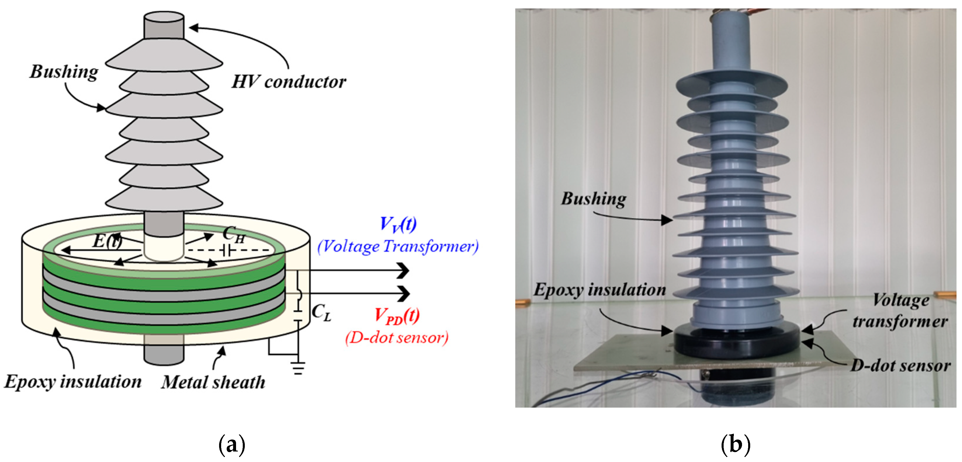
2.1. PRPD sensor embedded in a bushing
2.2. Signal Transducer
3. Experiment and Method
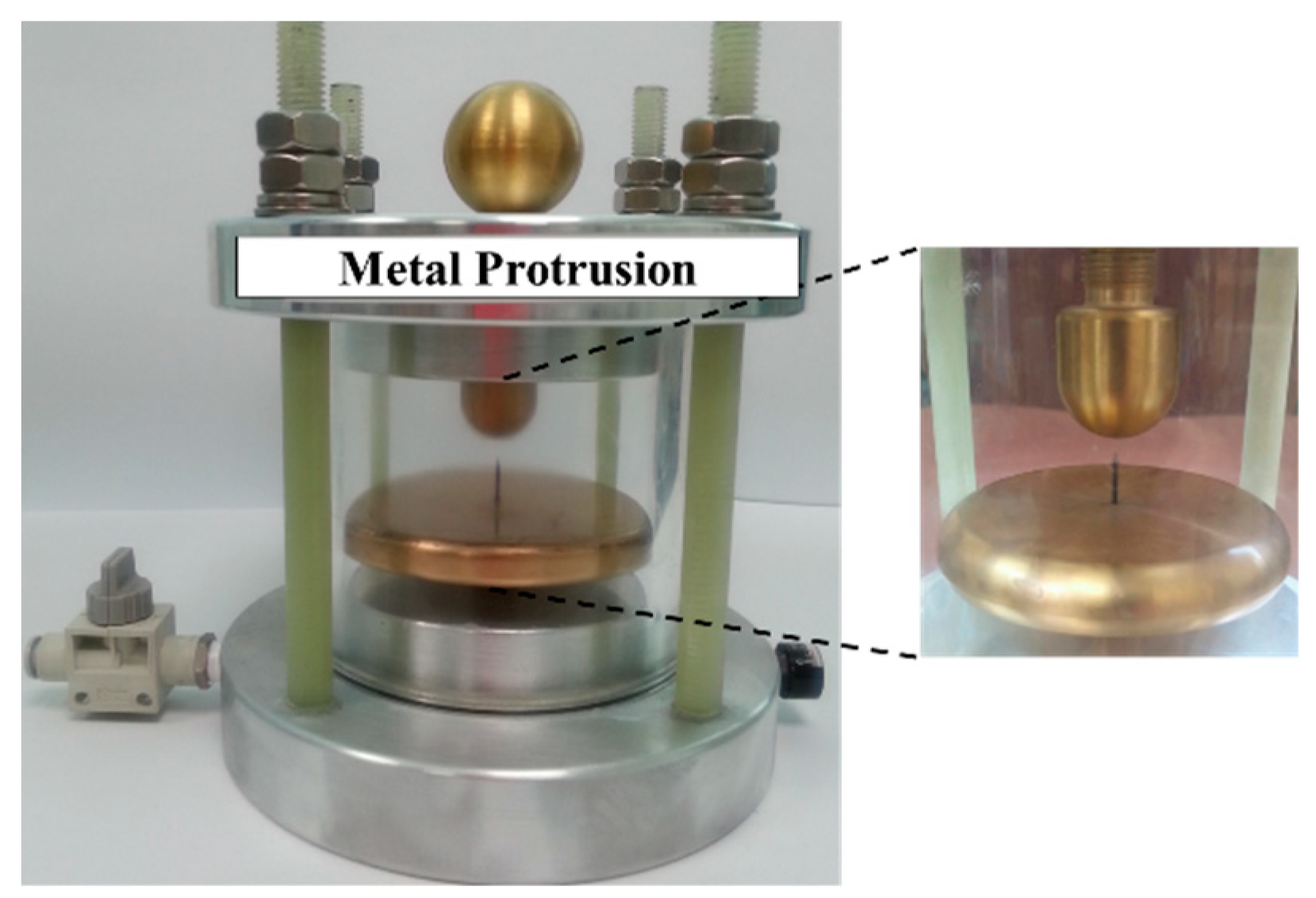
3.1. PD Simulator
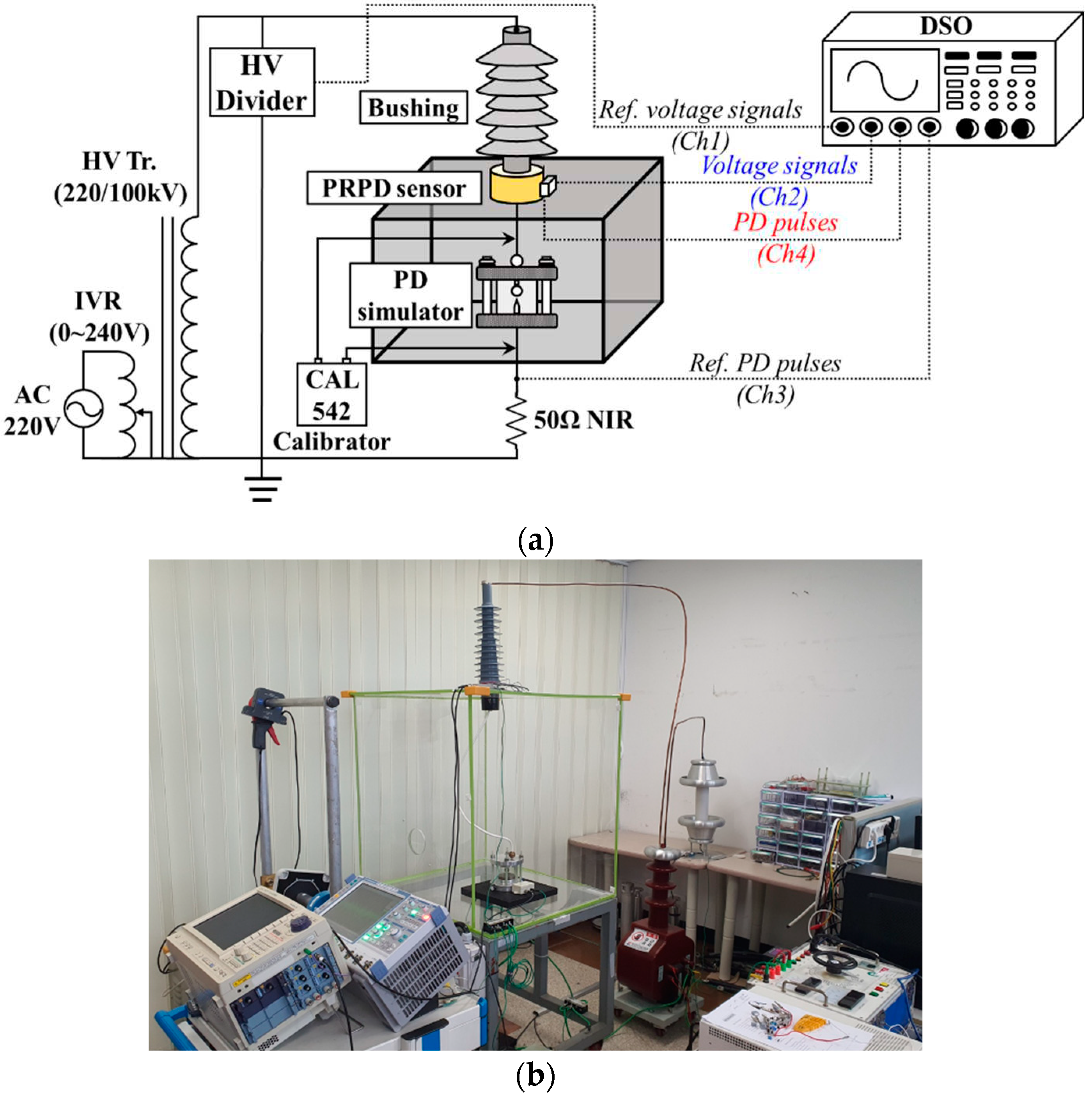
3.2. Experimental Setup
4. Performance Evaluation
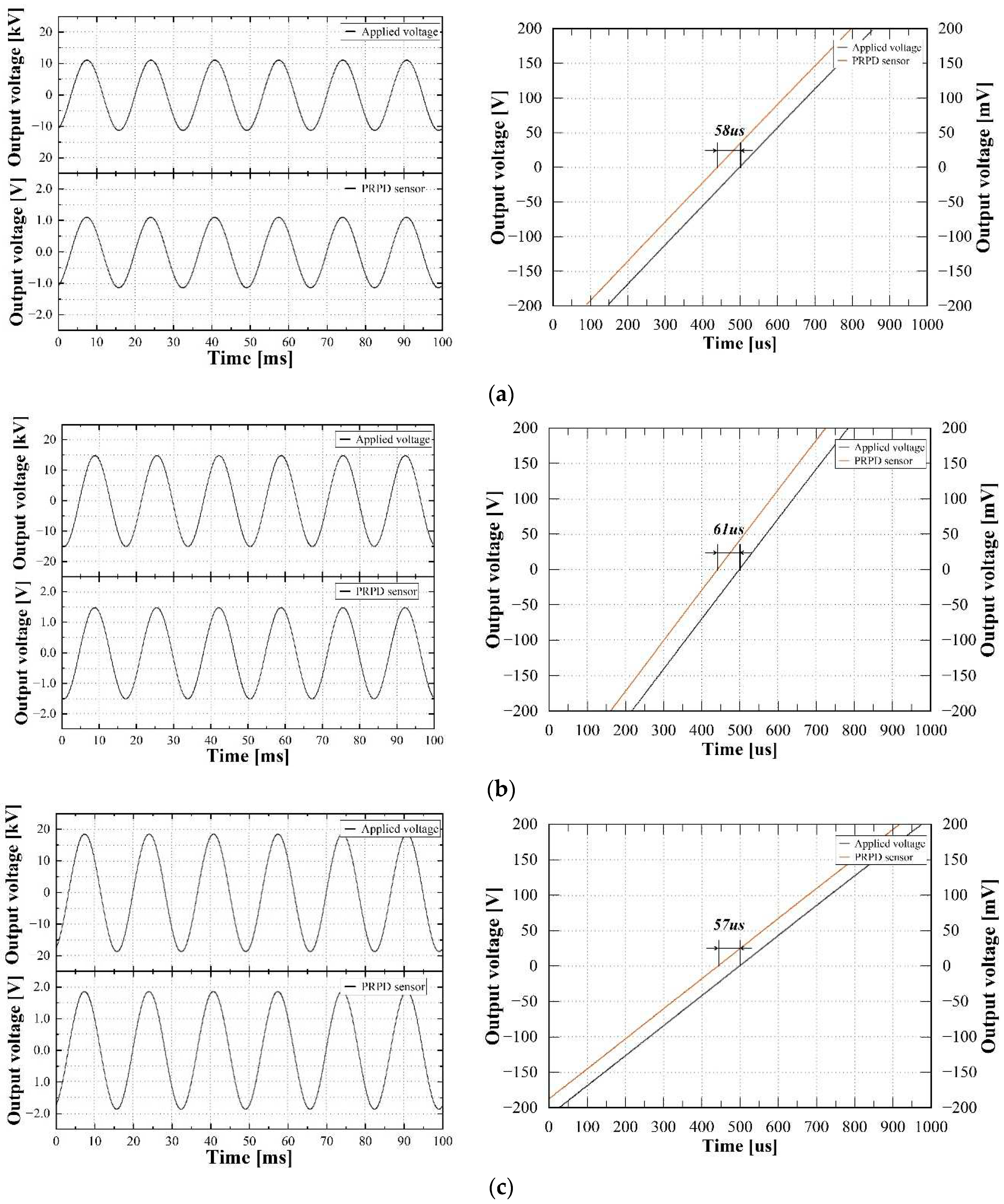
4.1. Voltage Measurement
5. Conclusions
- A.
- Voltage measurement
- B.
- PD detection
Author Contributions
Funding
Conflicts of Interest
References
- IEC 60270: High-Voltage Test Techniques – Partial Discharge Measurements; 2000.
- CIGRE WG D1.33; High-voltage On-site Testing with Partial Discharge Measurement. CIGRE Tech. Broch. 2012, 502.
- Chai. H.; Phung. B.T.; Mitchell. S.; Application of UHF Sensors in Power System Equipment for Partial Discharge Detection: A Review. Sensors 2019, 19, 1029. [CrossRef]
- F. H. Kreuger; Partial Discharge Detection in High Voltage Equipment. Butterworth 1989, 129.
- Liu. J.; Zhang. G.; Dong. J.; Wang. J. Study on Miniaturized UHF Antennas for Partial Discharge Detection in High-Voltage Electrical Equipment. Sensors 2015, 15, 29434-29451. [CrossRef]
- CIGRE WG D1.37; Guidelines for Partial Discharge Detection using Conventional (IEC60270) and Unconventional Methods. CIGRE Tech. Broch. 2016, 662.
- 7. M. Wu; H. Cao; J. Cao; H. L. Nguyen; J. B. Gomes; S. P. Krishnaswamy; An overview of state-of-the-art partial discharge analysis techniques for condition monitoring. IEEE Electr. Insul. Mag. 2015, 31, 22-35. [CrossRef]
- Wang. X.; Li. X.; Rong. M.; Xie. D.; Ding. D.; Wang. Z.; UHF Signal Processing and Pattern Recognition of Partial Discharge in Gas-Insulated Switchgear Using Chromatic Methodology. Sensors 2017, 17, 177. [CrossRef]
- Schichler. U.; Koltunowicz. W.; Gautschi. D.; Girodet. A.; Hama. H.; Juhre. K.; Lopez-Roldan. J.; Okabe. S.; Neuhold. S.; Neumann. C.; Pearson. J.; Pietsch. R.; Riechert. U.; Tenbohlen. S.; UHF Partial Discharge Detection System for GIS: Application Guide for Sensitivity Verification. IEEE Trans. Dielectr. Electr. Insul. 2016, 23, 1313-1321. [CrossRef]
- CIGRE WG B3.24; Benefits of PD diagnosis on GIS condition assessment. CIGRE Tech. Broch. 2017, 674.
- S.W. Kim; N.H. Kim; D.E. Kim; T.H. Kim; D.H. Jeong; Y.H. Chung; G.S. Kil; Experimental Validation for Moving Particle Detection Using Acoustic Emission Method. Energies 2021, 14, 8516. [CrossRef]
- L. Lundgaard; B. Skyberg; A. Schei; A. Diessner; Method and instrumentation for acoustic diagnoses of GIS. CIGRE session, 2000, 15.
- M. Mondal; G. B. Kumbhar; Partial Discharge Localization in a Power Transformer: Methods, Trends, and Future Research. IETE Technical Review, 2017, 34, 504-513. [CrossRef]
- de Castro, B.A.; dos Santos, V.V.; Lucas, G.B.; Ardila-Rey, J.A.; Riehl, R.R.; Andreoli, A.L. A Comparative Analysis Applied to the Partial Discharges Identification in Dry-Type Transformers by Hall and Acoustic Emission Sensors. Sensors 2022, 22, 1716. [CrossRef]
- Sikorski, W.; Wielewski, A. Low-Cost Online Partial Discharge Monitoring System for Power Transformers. Sensors 2023, 23, 3405. [CrossRef]
- G.C. Shin; S.W. Kim; G.S. Kil; Comparison between the PD Characteristics of g3 and Dry Air for Gas-Insulated Switchgears. Energies 2022, 15, 7043, . [CrossRef]
- R. Bozzo; L. Centurioni; F. Guastavino; Measuring the Endurance of Films in Partial Discharges. IEEE Trans Dielectr. Electr. Insul. 1993, 28, 1050-1056. [CrossRef]
- Z. Lu; Z. Li; S. Lu; M. Xu; W. Liu; Fault Mechanism Analysis of Voltage Transformer Caused By Iron Core Saturation. 2022 IEEE 6th Advanced Information Technology, Electronic and Automation Control Conference (IAEAC) 2022, Beijing, China, 856-859. [CrossRef]
- Y. Xiao; J. Fu; B. Hu; X. Li; C. Deng; Problems of voltage transducer in harmonic measurement. IEEE Trans. Pow. Deliv. 2004, 19, 1483-1487. [CrossRef]
- Mingotti. A; Costa. F; Pasini. G; Peretto. L; Tinarelli. R; Modeling Capacitive Low-Power Voltage Transformer Behavior over Temperature and Frequency. Sensors 2021, 21, 1719. [CrossRef]
- IEC 61869-11: Instrument transformers - Part 11: Additional requirements for low-power passive voltage transformers, 2017.
- IEC 60044-7: Instrument transformers - Part 7: Electronic voltage transformers, 1999.
- IEC 61869-13: Instrument transformers - Part 13: Stand-alone merging unit (SAMU), 2021.
- Wagoner, T. C. at el; Differential-output B-dot and D-dot monitors for current and voltage measurements on a 20-MA, 3-MV pulsed-power accelerator. Physical Review Special Topics - Accelerators and Beams 2008, 11, 100401. [CrossRef]
- J. Wang; S. Ban; Y. Yang; A Differential Self-Integration D-Dot Voltage Sensor and Experimental Research. IEEE Sensors J. 2015, 7, 3846-3852. [CrossRef]
- N.H. Kim; D.E. Kim; S.W. Kim; J.H. Kim; G.S. Kil; Development of Electronic Voltage Transformer for Electric Rolling Stocks. J. Korean Soc. Railw. 2023, 26, 445-453. [CrossRef]
- Wang. J.; Gao. C.; Yang. J.; Design, Experiments and Simulation of Voltage Transformers on the Basis of a Differential Input D-dot Sensor. Sensors 2014, 14, 12771-12783. [CrossRef]
- L. Yao; J. Huang; N. Kang; T. Shen; D. Liu; F. Zhang; H. Sun; Compensation of the offset in numerical integration of a D-dot sensor measurement. Proceedings of 2014 3rd Asia-Pacific Conference on Antennas and Propagation, Harbin, China, 2014, 898-901. [CrossRef]
- G. A. Hussain; M. Shafiq; M. Lehtonen; M. Hashmi; Online Condition Monitoring of MV Switchgear Using D-Dot Sensor to Predict Arc-Faults. IEEE Sensors J. 2015, 15, 7262-7272. [CrossRef]
- G. A. Hussain; G, Amjad; A, A, Zaher; D, Hummes; M, Safdar; M, Lehtonen; Hybrid Sensing of Internal and Surface Partial Discharges in Air-Insulated Medium Voltage Switchgear. Energies 2020, 13, 1738. [CrossRef]
- M. Rostaghi-Chalaki; K. Yousefpour; J. P. Donohoe; M. Kurum; C. Park; J. Klss; Design of Transmission Line and Electromagnetic Field Sensors for DC Partial Discharge Analysis. IEEE Trans Dielectr. Electr. Insul., 2020, 27, 2138-2146. [CrossRef]
- Jin. M.; Li. H.; Liu. S.; Identification and Compensation for D-Dot Measurement System in Transient Electromagnetic Pulse Measurement. Sensors 2022, 22, 8538. [CrossRef]
- S.W. Kim; J.R. Jung; Y.M. Kim; G.S.Kil; G. Wang; New Diagnosis Method of Unknown Phase-shifted PD Signals for Gas Insulated Switchgears. IEEE Trans Dielectr. Electr. Insul. 2018, 25, 102-109. [CrossRef]
- J.H. Lee; N. Hozumi; T. Okamoto; Discrimination of phase-shifted partial discharge patterns by neural network using standardization method. Proceedings of 1994 IEEE International Symposium on Electrical Insulation 1994, Pittsburgh, USA, 314-317. [CrossRef]

| Parameter | Value | |
|---|---|---|
| Diameter | Φ 160 mm | |
| Height | 12 mm | |
| Sensing electrodes (Voltage and PD) |
Width | 3 mm |
| Thickness | 1 oz | |
| Insulation layer | 0.2 mm | |
| Dielectric constant (εs) | 4.7 | |
| Voltage level | Applied voltage [kV] |
PRPD sensor [V] |
Corrected error ratio [%] |
Corrected phase error [min] |
||
|---|---|---|---|---|---|---|
| Measured value |
Accuracy class of 0.2 | Measured value |
Accuracy class of 0.2 | |||
| 10.561 | 1.056 | 0.001 | 0.2 | - 0.83 | 10 | |
| 13.204 | 1.322 | 0.126 | + 3.06 | |||
| 15.803 | 1.583 | 0.166 | - 2.13 | |||
Disclaimer/Publisher’s Note: The statements, opinions and data contained in all publications are solely those of the individual author(s) and contributor(s) and not of MDPI and/or the editor(s). MDPI and/or the editor(s) disclaim responsibility for any injury to people or property resulting from any ideas, methods, instructions or products referred to in the content. |
© 2023 by the authors. Licensee MDPI, Basel, Switzerland. This article is an open access article distributed under the terms and conditions of the Creative Commons Attribution (CC BY) license (http://creativecommons.org/licenses/by/4.0/).


