1. Introduction
Modern communication and sensing technologies such as remote sensing (RS) or 5G communications heavily rely on antenna arrays to maximize energy efficiency and performance. For instance, RS is a technology embedded with interdisciplinary sciences that aims to gather information and analyze objects without making any kind of physical contact. The idea of it had an origin for topographic mapping of Earth’s surfaces when the camera was first invented. The technology has flourished in many sectors in addition to its original purpose of surface mapping mainly related to geography. For instance, one widely known instrument based on this technology is the geographic information system (GIS) [
1,
2]. The application of remote sensing technologies has been increasingly seen in transportation systems and vehicles due to the growing developments in assisted and autonomous driving technologies [
3]. Remote sensing sensors for data collection [
4,
5] have witnessed tremendous developments in recent years.
RS sensors are instruments that measure the properties of EM radiation reflected from an object’s surface. In general, radiance is the property measured as a function of wavelength but could also include other parameters such as cross-polarization ratio. Technology for developing microwave sensors is quite different from that of optical-infrared (OIR) sensors [
6]. Sensors based on microwave spectrum have two advantages: data packages about certain geographic locations can be gathered despite weather conditions; the RS parameter related to polarization can be acquired.
The ability of remote sensing sensors to provide accurate and reliable data on weather and road surface conditions was investigated in [
7]. These conventional sensors based on infrared radiation or spectroscopic methods have shown a limited distance coverage (i.e., up to 15 meters) and the accuracy is heavily dependent on in situ conditions. Future intelligent transportation systems (ITSs) will need to collect various information about the surroundings of the vehicle regardless of weather conditions in order to improve mobility, transport safety, and comfort while also reducing the negative impacts on the environment. Phased arrays with multi-dimensional electronic scanning capability show advantages in ITS [
8,
9] and remote sensing systems [
10]. By utilizing high data rate wireless communication technologies in addition to sensing, transportation systems can be improved and redesigned with the use of the data uncovered using remote sensing in combination with wireless communications. Moreover, recently dual-function systems have been proposed to combine sensing and communications on the same platform for vehicular networks to further improve both energy efficiency and system performance [
17].
The main sensing technologies for ITS are summarized and compared in
Table 1, which demonstrates that sensing with electromagnetic waves such as in integrated communication and sensing systems and radars provides high accuracy and significant advantages over other methods in complex environments. Low-cost and compact antenna arrays and beamforming technologies are necessary in modern vehicular systems to provide high-accuracy sensing and high data rate communications.
The antenna or elements generally behave very differently when they are isolated or in an array. The impedance, radiation pattern, and efficiency of the antennas in an array are dominated by the mutual coupling with the neighboring elements. The spacing between the elements and the geometry of the array influence the mutual coupling [
19]. Mutual coupling may be utilized to increase the bandwidth of the antenna arrays [
20]. The characteristics of mutual coupling in an array are complex, in particularly, for non-planar arrays, for instance, cylindrical conformal arrays. Therefore, it is important to study and understand mutual coupling and its benefits and disadvantages in non-planar arrays, especially in the case of multibeam applications.
Unlike a planar antenna array, a cylindrical conformal array (CCA) can provide omnidirectional coverage around the antenna array [
19,
20,
21]. This feature is not typically required for tracking or detecting services. However, it is desired for scientific applications in remote sensing, e.g., Cylindrical Polarimetric Phased Array Radar (CPPAR) is capable of maintaining broadside polarimetric purity at all azimuthal directions [
22]. The angular measurement errors of differential reflectivity on the order of 0.1 dB were expected for polarimetric weather radar missions. This is a substantial challenge to achieve for planar arrays due to azimuth scan losses and the large polarization bias that occurs when the main lobe is steered away from the principal planes [
23]. The arrays on a cylinder can be analyzed by employing Bessel functions to obtain solutions for active element patterns and mutual coupling relationship between elements which is typically represented by an impedance matrix [
24].
In this study, an ultrawideband cylindrical array based on tightly coupled crossed disk elements is investigated. This array structure was chosen for scrutinizing the mutual coupling effect because coupling in this arrangement is essential for the array to obtain broad bandwidth. The cylindrical array is in a dual slant-polarized configuration and mutual coupling between the elements was significant to achieve a low profile. The effect of mutual coupling with respect to impedance matching and radiation characteristics of the elements in the array is examined. The potential of such arrays for multi-beam capability is explored based on studies on the subarrays.
As the technology for ITSs is developed, the demand for the coverage of both a wider range and a broader spectrum increases. In addition, polarimetric measurement with a high polarization purity is critical to improve classification accuracy in certain conditions. The dual slant-polarized cylindrical array based on the tightly coupled crossed disk antennas presented advantages in all aspects of concern.
In
Section 2, the dual slant-polarized cylindrical array for a study on the mutual coupling effect is described.
Section 3 analyzes the effect of mutual coupling with respect to impedance matching and radiation characteristics. The results and discussion are presented in
Section 4, and finally, a conclusion is drawn in
Section 5.
2. The Cylindrical Array Design
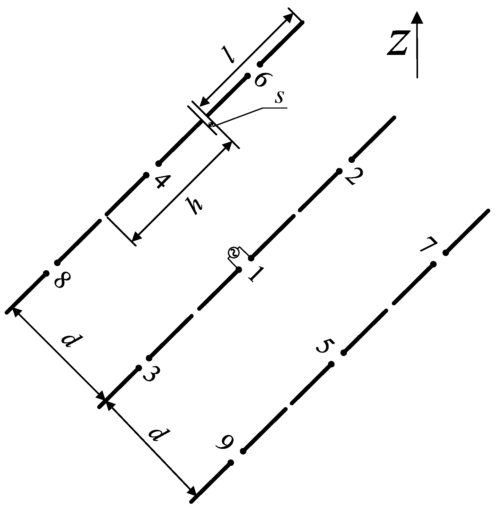
When two or more antennas are placed close to each other, an interchange of energy occurs. It happens whether the antennas are in transmitting or receiving mode. The energy exchange between the antenna elements in the array is caused by mutual coupling. The mutual coupling changes the terminal impedance, antenna gain, beamwidth, and efficiency of the array. In order to investigate this effect more thoroughly on a cylindrical surface with a more complex elements structure, a dipole array as shown in
Figure 1 is examined first. The mutual coupling between the element ”1” with a length
l and the surrounding elements with side-by-side configuration is expressed by [
25]
where
and
are the sine and cosine integral functions, and
d is the distance between the two dipoles of interest at the feed point.
For the collinear configuration, the mutual impedance is expressed by
For the parallel-in-echelon configuration, the mutual impedance is expressed by
The total antenna efficiency is used to take into account losses at the input terminals and within the structure of the antenna. The total efficiency of the elements in the array is related to the impedance matching status partially dependent on the mutual coupling effect. The total efficiency and the active input impedance of the element have the following relationship,
where
is the voltage reflection coefficient at the input terminals of the antenna,
is antenna input impedance,
is the characteristic impedance of the transmission line.
where
is reflection efficiency.
where
is total antenna efficiency,
is conduction efficiency,
is dielectric efficiency.
where
=
is the antenna radiation efficiency [
26]. It is usually implicit to compute and measure, however, it can be obtained from full-wave simulations with high accuracy and it is adopted in this investigation.
The calculated terminal impedance, mutual coupling coefficients, active input impedance, and the total radiation efficiency of the element ”1” in the presence of other 8 elements were given in
Table 2. It indicated that as the number of active elements increases, the real part fluctuates around the characteristic value, and the absolute value of the imaginative part of the input impedance tends to decrease, hence, the total radiation efficiency of the center element also tends to decrease. The total radiation efficiency reaches 99 % with all 9 elements becoming active. However, the operational bandwidth of such arrays is limited. Hence, mutually coupled disk arrays were designed and studied, furthermore, they were put on a curved surface for low profile and accommodating array carriers of uneven surfaces, the unique features of such arrays were investigated based on disk arrays with enhanced mutual coupling.
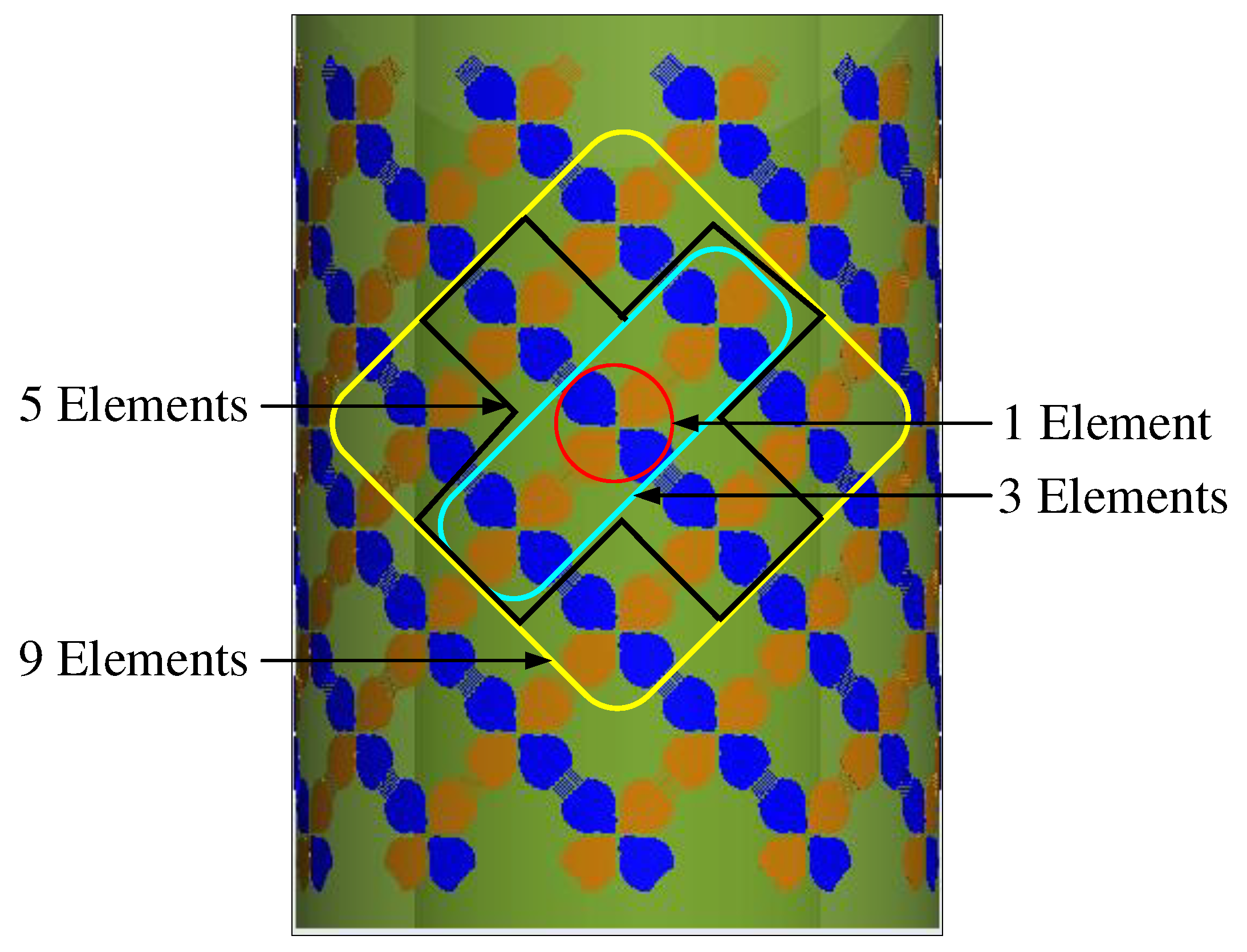
The array formed by coupling enhanced disk pairs demonstrated broad bandwidth characteristics. It is also bendable to make it deployable on curved surfaces. The wideband cylindrical array design is shown in
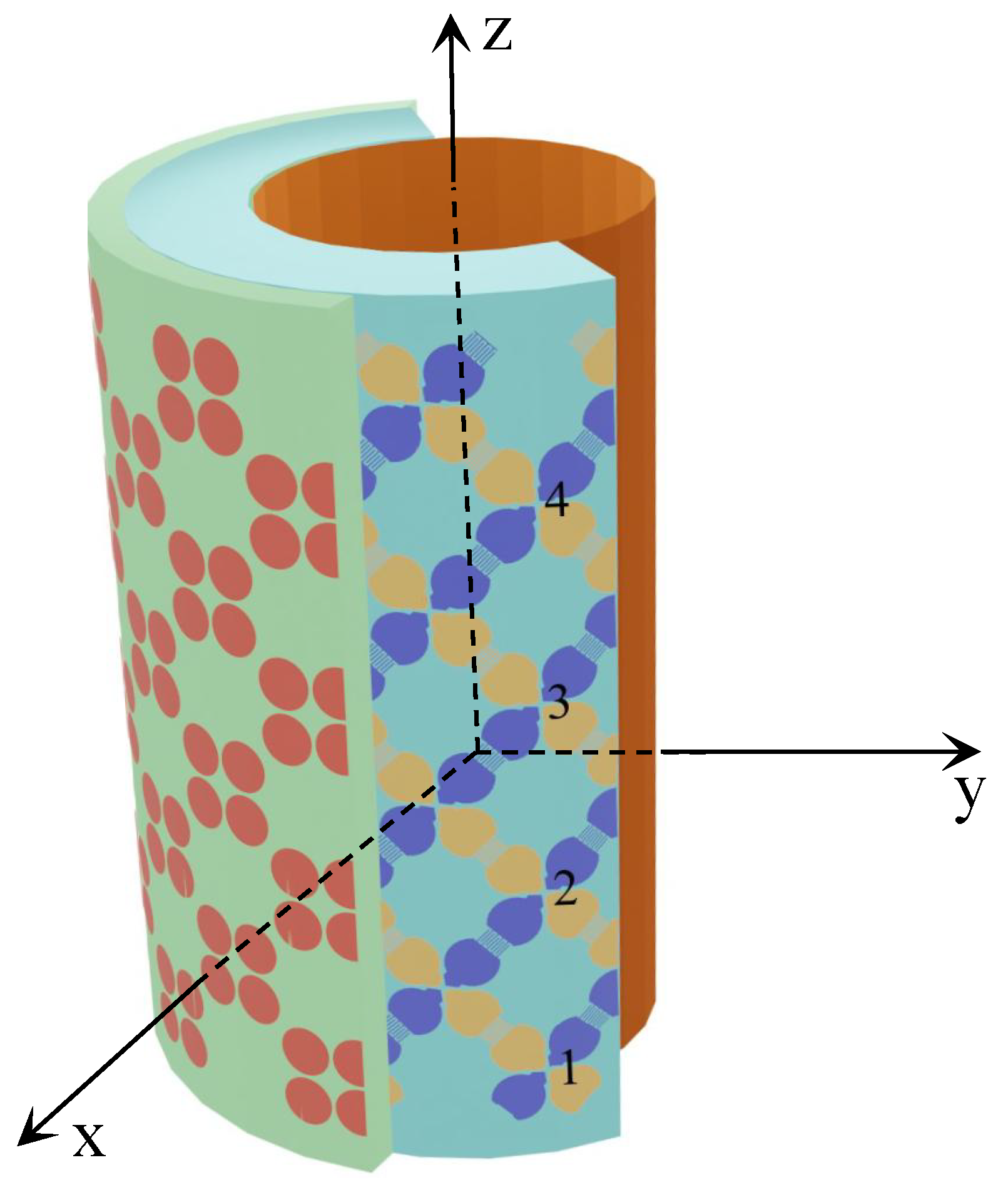
Figure 2. It consists of three layers, one active layer of tightly coupled crossed disks in the middle and one metasurface on the outside, backed up by a ground plane in the core of the cylinder with a smaller radius and hollow inside. These three layers are concentric. Four subarray configurations are also illustrated where 1, 3, 5, or 9 elements are included in the subarray respectively. The cross-section view of the cylindrical array is shown in
Figure 3.
3. Mutual Coupling in a Cylindrical Array
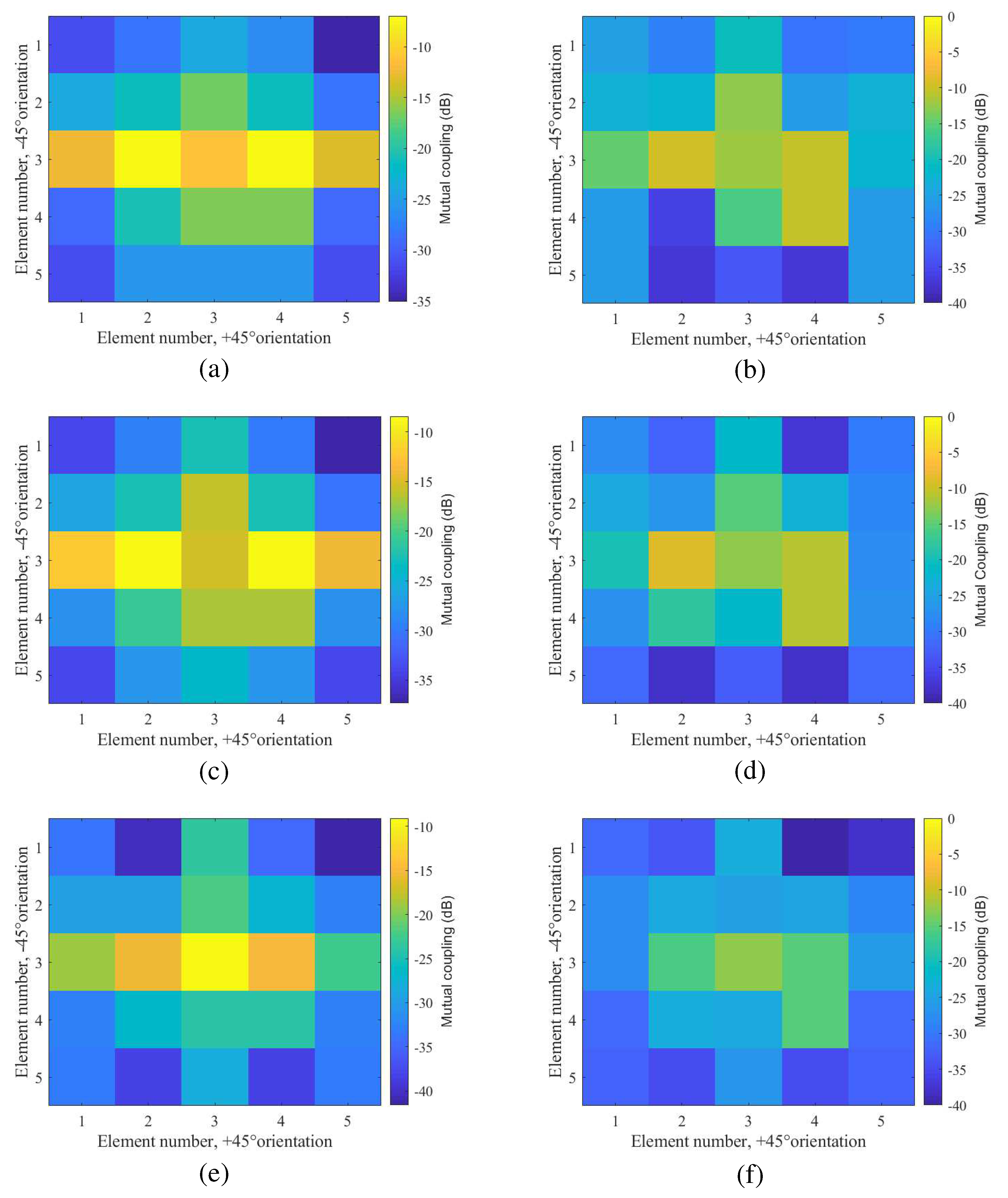
The mutual couplings between the center element and its surrounding elements in the cylindrical array and its corresponding reference planar array are illustrated in
Figure 4 for comparison, where (3,3) represents the physical location of the center element. The element in the center with 4 other adjacent elements (two at each side in +
, i.e., the orientation for co-polarization) formed the center row of the 5 × 5 subarray. Three frequencies of 3 GHz, 4 GHz, and 5.9 GHz were studied for the element in the two forms of the array.
It is clearly shown in
Figure 4 that mutual coupling between the elements in a planar array is spreading over a greater electrical distance than the same elements in a cylindrical form. In other words, the mutual coupling effect in a cylindrical array can be observed only between a few surrounding elements rather than being observed across the 5 × 5 subarray. This implied that a small subarray (with 3 × 3 elements in it) of the cylindrical array can demonstrate the potential benefits of the full array in particular the operation frequency bandwidth. This unique feature enables the cylindrical array to form agile multiple beams with a relatively low profile. It was also noticed that the center element has a stronger coupling with the elements in the same row—colinear position than the elements in the parallel rows. Hence, irregular subarrays can be formed with more elements in the center row to improve its radiation performance.
Three aspects of array characteristics have been investigated including impedance matching, far-field radiation patterns, and multibeam scan capability. They are all closely related to the mutual coupling effect with its different role in planar arrays being compared and analyzed.
In a cylindrical array, the mutual impedance
between the element
n and the element
m in the paraxial region can be calculated in closed form by analyzing the surface tangential field at the position of the
mth element excited by a hypothetical current source (with the current mode,
) representing the element
n, it is simply given by
where
is the field due to source
and
is the area occupied by source
. The current modes are assumed sinusoidal current sources (with an infinitesimal length, approximately 0.05
) along the polarized direction of the element. Relation between
and
can be represented by a dyadic Green’s function. As the tangential components of the dyadic Green’s function are periodic, hence, it can be approximated by a Fourier series (FS). The oscillatory nature of the coupling as the separation changes indicated that there are at least two types of field contributions adding in and out of phase. This characteristic was demonstrated in
Table 2 and
Figure 4, where for a fixed separation between two elements, mutual coupling changes with frequency in a periodic manner.
3.1. Effect on Impedance Matching
The active reflection coefficient for the element
m at a scan angle
for a finite array has the following relation with the scattering parameters,
where (
,
) is the position of the element
n,
k is the wavenumber,
is the scattering parameter demonstrating mutual coupling between two elements of
m and
n, and
N is the total number of elements in the array for observation.
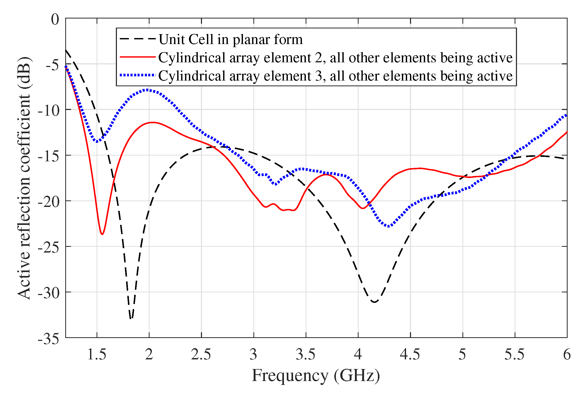
Figure 5 shows the active reflection coefficient of the center elements (the elements “2” and “3” shown in
Figure 3) in the cylindrical array, compared with the active reflection coefficient of the unit cell for the reference planar array at the broadside scan. It indicated that with fewer elements in the cylindrical array configuration, the array elements can work collaboratively over a broad frequency bandwidth, and more active elements are needed in the case of a planar array.
Table 3.
The input impedance of the center element and total efficiency of the subarrays.
Table 3.
The input impedance of the center element and total efficiency of the subarrays.
| Frequency |
Number of mutual
coupling elements |
S-Parameters
dB |
|
Total antenna efficiency
dB (%) |
| 1.7 G |
1 |
-3.9486 |
62.82-j130.66 |
-2.2391 ( 59.72) |
| |
3 |
-3.9204 |
27.76-j24.12 |
-2.2583 (59.45) |
| |
5 |
-8.0147 |
53.00-j16.81 |
-0.7466 (84.20) |
| |
9 |
-30.1146 |
116.16-j6.29 |
-0.0042 (99.90) |
| 2.5 G |
1 |
-8.3272 |
77.3413-j67.655 |
-0.6904 (85.30) |
| |
3 |
-7.8620 |
76.310+j72.498 |
-0.7759 (83.64) |
| |
5 |
-17.0512 |
140.95+j30.367 |
-0.0865 (98.03) |
| |
9 |
-17.0527 |
139.46-j31.102 |
-0.0865 (98.03) |
| 4 G |
1 |
-14.5749 |
95.351-j32.346 |
-0.1542 (96.51) |
| |
3 |
-5.8523 |
362.52-j47.795 |
-1.3070 (74.01) |
| |
5 |
-11.7313 |
194.92-j33.444 |
-0.3018 (93.29) |
| |
9 |
-14.1703 |
161.27-j37.123 |
-0.1695 (96.17) |
| 5.9 G |
1 |
-12.4752 |
81.31+j29.03 |
-0.2528 (94.34) |
| |
3 |
-13.8363 |
91.36-j32.73 |
-0.1834 (95.87) |
| |
5 |
-16.3371 |
99.60-j26.86 |
-0.1021 (97.68) |
| |
9 |
-16.9269 |
91.5265+j9.96 |
-0.0890 (97.97) |
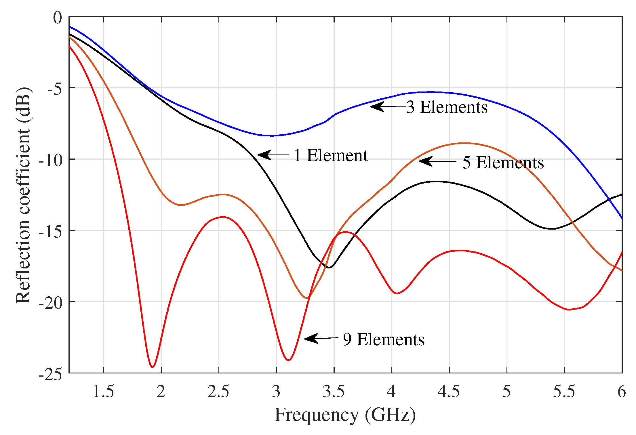
Figure 6 shows the active reflection coefficient of the center element in the subarrays consisting of 1, 3, 5, and 9 elements respectively. It clearly indicated that as the number of active element in subarrays increases, the input impedance becomes more matched; and the active reflection coefficient is lower and better. For the subarray of 9 active elements, the operational band of the center element covered frequency from 1.7 GHz to 6 GHz entirely.
3.2. Effect on the Radiation Pattern
The active element pattern of the array is considered when a single element is excited when all other array elements are terminated with matched loads. In this case, the radiation pattern of the array is significantly affected by the position of the element that is excited. Moreover, all mutual coupling effects also influence the radiation pattern.
The array beam pattern is calculated by
where the array factor (
) describes the spatial response of all array elements. For the element pattern (
), unlike the traditional element pattern in a planar array, the normal of each array element is oriented in a different direction in a conformal array. The element pattern can be defined by
where
and
is the spatial unit vector, and
is the normal vector for the
ith element position.
The radiation patterns of the subarrays consisting of different numbers of elements are investigated. The patterns were synthesized under two different scenarios: 1) the radiation patterns of the subarrays are generated while all the other elements in the cylindrical array are terminated with matched loads; 2) the radiation patterns of the subarrays are produced while all the rest elements are left open.
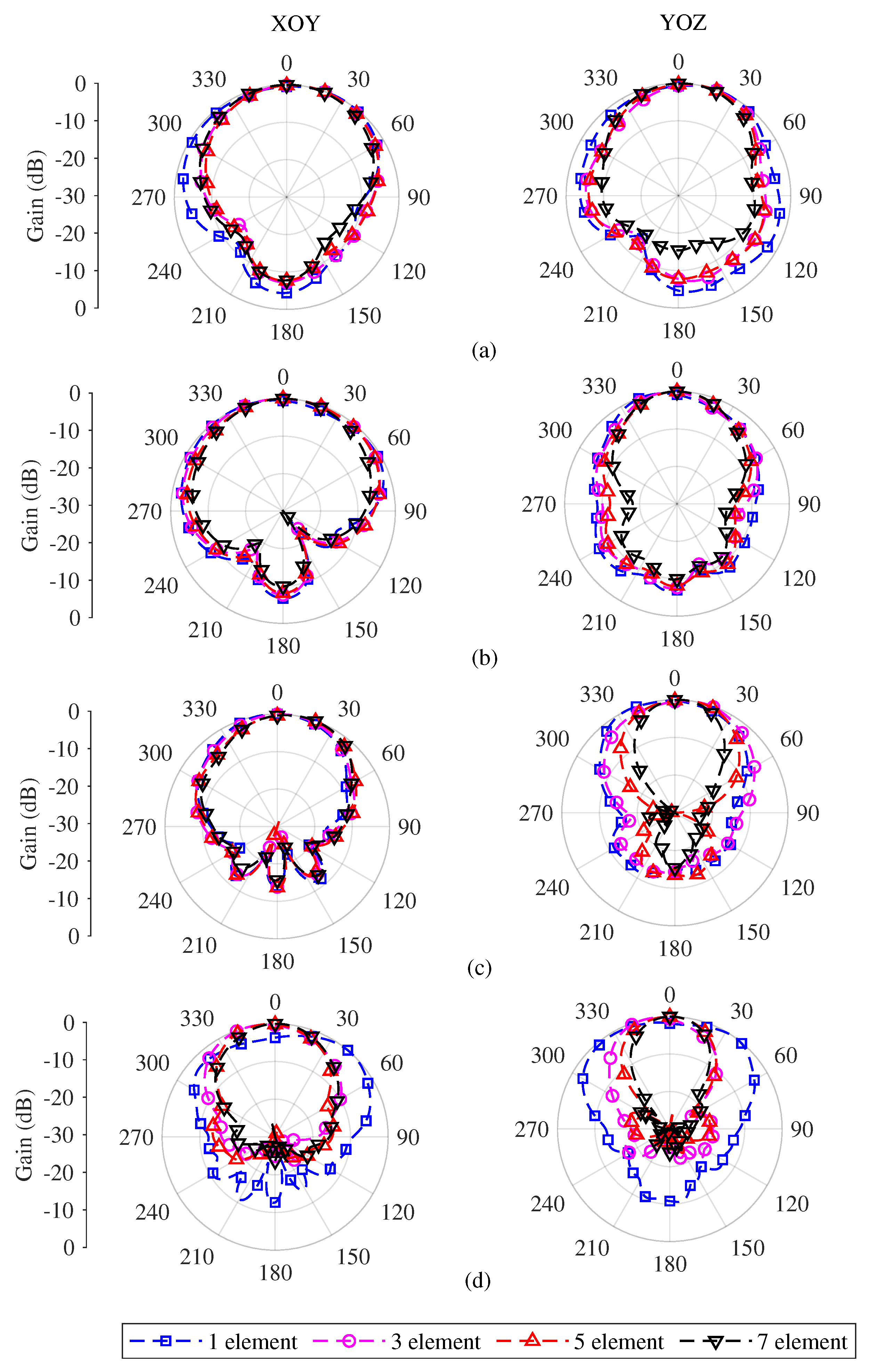
The radiation patterns for 4 subarray scenarios on the cylindrical surfaces were compared in
Figure 7. The number of elements in the subarrays is 1, 3, 5 and 9 respectively, and the radiation patterns of four frequencies have been given. As expected, as the number of elements in the subarray increases, the beamwidth becomes narrower. The pattern in
- plane is narrower than in the
-plane, which reflects the dipole-like nature of such antenna elements. The characteristics of the radiation patterns of subarrays are summarized in
Table 4, and the intermediate frequency of 4 GHz is selected. As expected the 3 dB beamwidth becomes gradually narrower in both planes as the number of active elements increases. The scenario with 3 elements in the subarray shows a slightly odd feature than other cases it may be due to poor impedance matching as shown in
Figure 6.
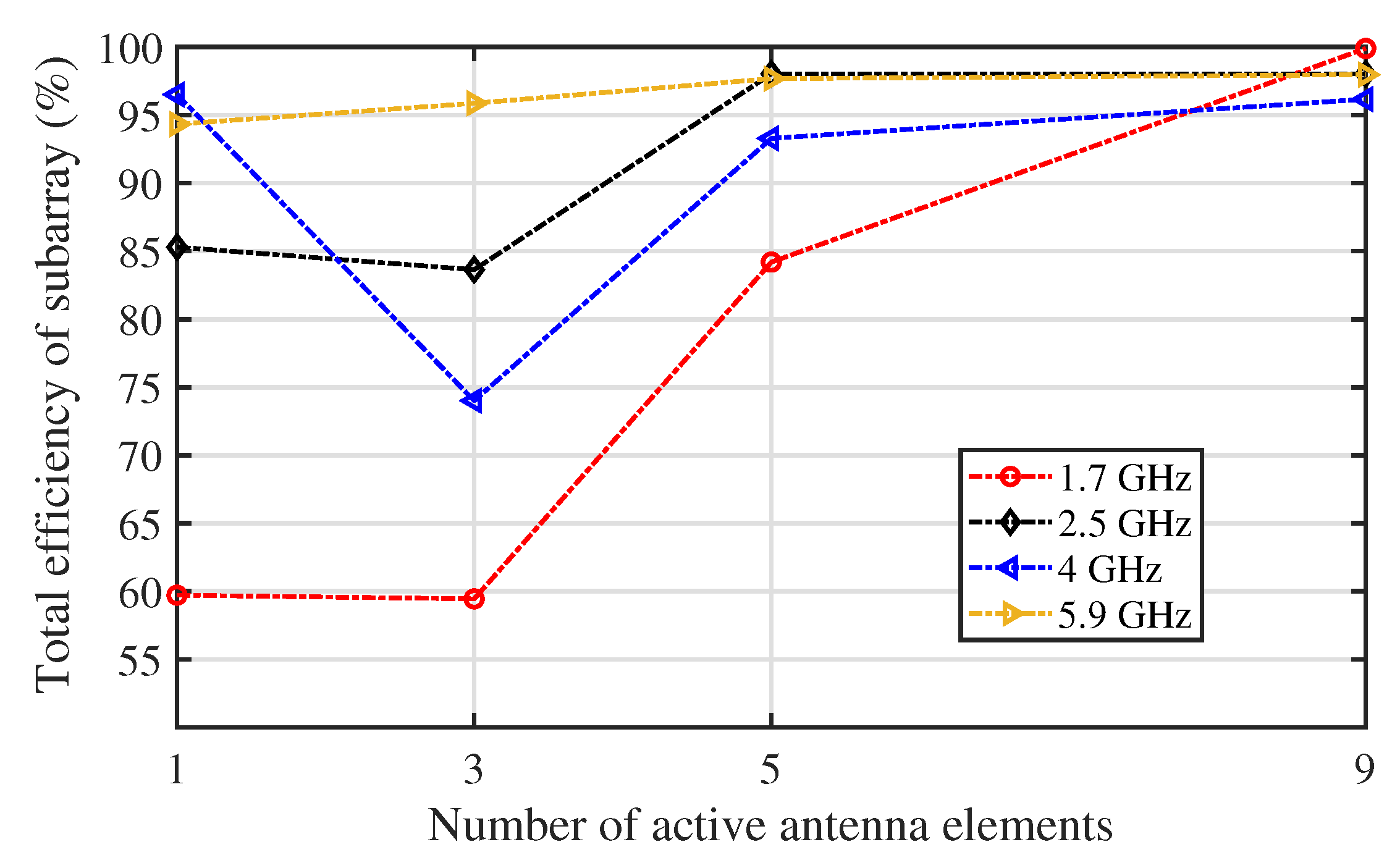
The change in the total efficiency of the subarrays formed by different numbers of elements is shown in
Figure 8. The trend is clear that the total efficiency of the subarrays increases with the total number of active elements in the subarrays. This is in particular more obvious at the low frequency where mutual coupling between the adjacent elements plays a more significant role in improving impedance matching and accordingly the efficiency. However, there is an exception in certain frequencies such as at 4 GHz, where a degraded performance for the subarray with 3 elements is observed compared to that of a single active element, this is due to the phenomenon that the negative mutual coupling effect occurs, making the impedance matching worse. The deteriorated impedance matching from a single element to a subarray with 3 elements was shown in
Figure 6.
3.3. Multibeam Capabilities
As shown in the earlier study on mutual coupling, a significant coupling concentrated among only a few close elements is a unique characteristic of the cylindrical array based on the tightly coupled disk antennas. This feature can be adapted to produce multibeams by forming many subarrays on the cylindrical surface. The number of beams the array can produce depends on the impedance matching of the elements in the subarray, the total number of elements, the dimension of the array, and the beam characteristic required.
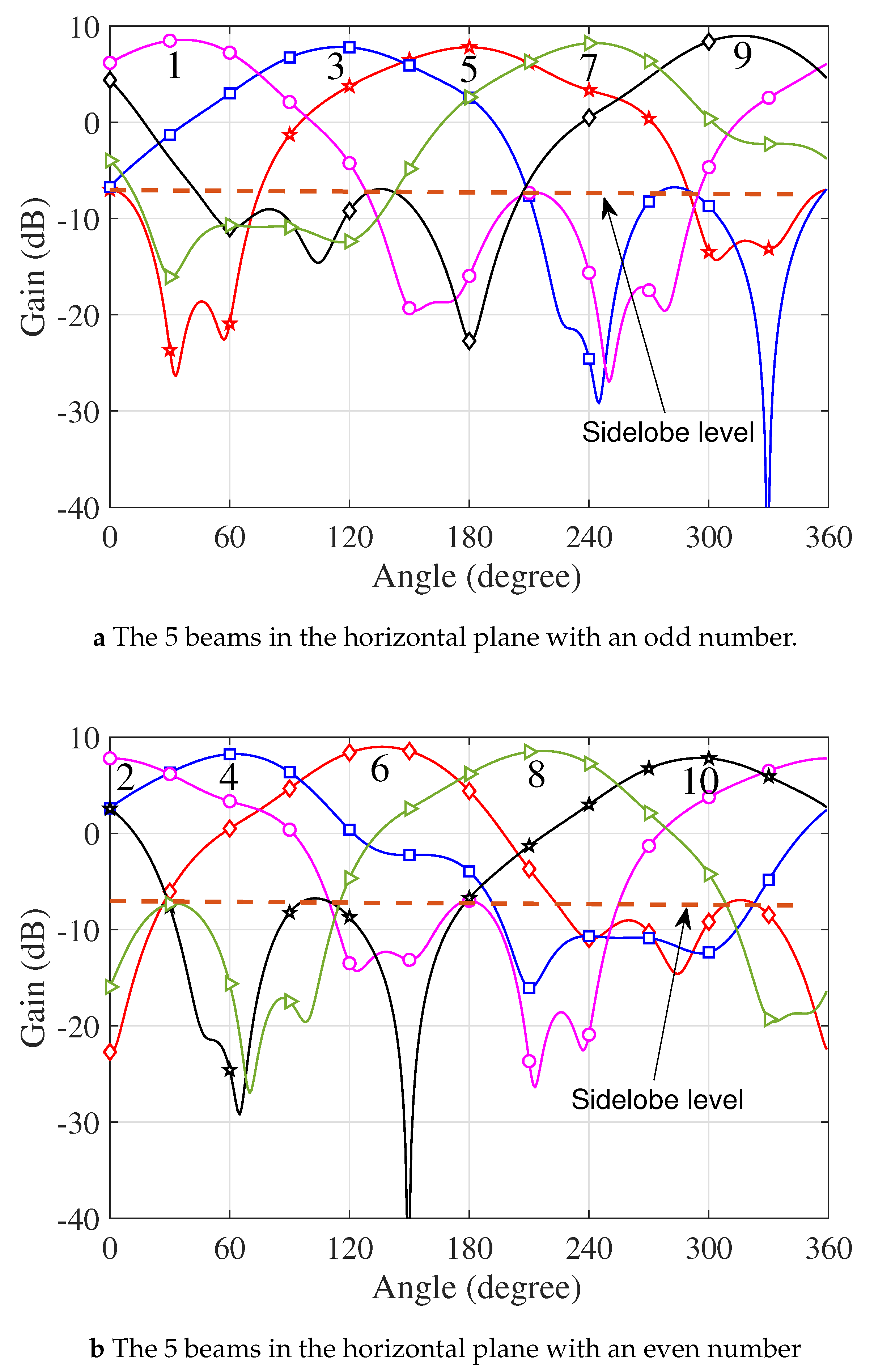
It was demonstrated that a subarray with 9 elements on the cylindrical surface yields a sound impedance matching for the center element of the subarray due to the mutual coupling effect. In the cylindrical array with 80 elements (dual polarized), as shown in
Figure 3, 10 beams were formed with 10 subarrays—they were distributed uniformly in the horizontal plane. The radiation patterns for the 10 subarrays (of 9 elements in each subarray) are shown in
Figure 9. The characteristics of the radiation beams of the subarrays of different sizes at 2.5 GHz are summarized in
Table 4. For the subarray with a size of 3×3, a gain of 10.54 dB can be obtained from each subarray and 10 subarrays on the cylindrical surface can cover the entire horizontal space. The 3-dB beamwidth in the elevation plane is over 40 degrees. The realized gains of all subarrays showed little discrepancy among them. Azimuth scan-invariant beam characteristics have been demonstrated.
4. Results and Discussion
To demonstrate the performance of the cylindrical array in the presence of significant mutual coupling and its advantages for multibeam capability, a compact cylindrical array with a diameter of 50 mm is examined following the design illustrated in
Figure 2. There are 80 dual-slant-polarized elements on the cylindrical surface. The height of the cylindrical array is 60 mm. The target operation frequency band ranges from 1.7 GHz to 6 GHz. The key aspects of the performance of the tightly coupled cylindrical array are compared with other existing array designs on convex surfaces in
Table 5. The dual slant-polarized cylindrical array based on tightly coupled crossed disks demonstrated a considerably wider bandwidth compared to other cylindrical arrays. The array investigated presented a higher mutual coupling between the adjacent elements reaching as high as -9 dB. Moreover, it has a compact structure, making it ideal for multibeam applications that also require a low-profile structure.
The impedance matching over a frequency bandwidth of 110% was yielded by the proposed cylindrical array. The broad impedance matching capability is related to the tight mutual coupling in the array. This is clearly indicated in
Figure 5 and
Figure 6. When more elements are in the subarray and become active, the operation frequency bandwidth becomes wider. The subarray consisting of 9 elements demonstrated the largest frequency bandwidth among the four subarray configurations—Active
of the center element is approximately below -15 dB.
Providing multiple beams is an important feature for antenna arrays to improve the scanning speed and increase the diversity gain. With a diameter of 50 mm, the proposed cylindrical array can produce 10 beams horizontally covering the entire horizontal plane by utilizing 10 subarrays with 80 elements of one polarization, some of the elements were shared between neighboring subarrays. At the center frequency of 4 GHz, the gain varied between 7.81 dB and 10.54 dB, 10 beams can be controlled to offer a fully agile coverage for the horizontal scan, and over 40 degrees coverage in the elevation domain is observed.
The efficiency of the array was investigated by monitoring the far-field radiation patterns under each subarray scenario in different frequencies. It is found that the improvement in efficiency due to the mutual coupling effect outweighs the concern about absorption-caused loss within the array. As illustrated in
Table 3 and
Figure 8, the total antenna efficiency of the center element significantly increased from approximately 60% to over 95 % in most of the frequencies across the band. It is also noticed when the number of active elements increases, the total antenna efficiency rises, e.g., at 1.7 GHz, the total antenna efficiency changed from 59.72% for one active element to 99.9% with 9 elements becoming active together. It is noticed that the efficiency at the low frequency increases more rapidly as the number of active elements rises.
Mutual coupling can affect the impedance of individual array elements and changes in impedance can lead to reflection and mismatch losses, it is conventionally one of the main concerns of mutual coupling to decrease the overall efficiency array. However, it is found from the cylindrical array that the enhanced mutual coupling plays a positive effect improving the efficiency instead of decreasing it, in particular at the low frequency.
It is worth mentioning that despite high mutual coupling between the array elements in the proposed cylindrical array, the negative effect on the radiation patterns were found to be minimal, and smooth radiation patterns were obtained for subarrays of different configuration as shown in
Figure 7. No anomalies in radiation patterns were observed from the low frequency 1.7 GHz to 6 GHz at the high frequency—even the mutual coupling was more pronounced at the low-frequency band.
Arrays with multibeam capability can be beneficial to ITS, particularly in the context of improving transportation efficiency and safety. Multibeam arrays could be used in sensor systems to improve the accuracy and coverage of data collection, as they can transmit and receive signals in multiple directions simultaneously, providing enhanced coverage and resolution compared to a single-beam system, e.g., 10 beams can be steered to produce a panorama view of the horizontal plane with a high resolution. The integration of multibeam arrays with ITS would depend on specific use cases and technological advancements. These concepts represent the ongoing efforts to make transportation systems more efficient, safe, and technologically advanced.
5. Conclusions
The effect of mutual coupling in the cylindrical conformal array based on tightly coupled disk antenna was investigated. It was revealed that enhanced mutual coupling was essential to obtain the ultrawide bandwidth desired from such arrays. The efficiency of the subarray increased due to the mutual coupling as it contributed to improve the impedance matching. Hence, more energy was transported by the subarrays. A significant mutual coupling exists only between the elements that are physically close to each other, and this feature can be used to form multibeams simultaneously spanning the entire azimuthal plane out of the cylindrical array. The array configuration shows a great prospect in intelligent transportation systems where data from omnidirectional monitoring and a broader spectrum is required.
Author Contributions
Conceptualization, X.L. and Y.Z.; methodology, X.L.; validation, X.L.; formal analysis, X.L.; investigation, X.L.; resources, Y.Z. and H.L.; writing—original draft preparation, X.L.; visualization, Y.F.; writing—review and editing, Q.S., Y.F., H.L., Y.Z., A.M. and M.T. All authors have read and agreed to the published version of the manuscript.
Funding
This work was supported in part by the National Natural Science Foundation of China under Grants 62174091 and 62201294, in part by Post-Doc International Exchange Programme Y20210098, in part by Nantong Science and Technology Plan Project (No. MS22022093) and Natural Science Foundation of The Jiangsu Higher Education Institutions of China (No. 23KJB580014).
Institutional Review Board Statement
Not applicable.
Informed Consent Statement
Not applicable.
Conflicts of Interest
The authors declare no conflict of interest.
Abbreviations
The following acronyms are used in this manuscript:
| AF |
Array Factor |
| CCA |
Cylindrical Conformal Array |
| CPPAR |
Cylindrical Polarimetric Phased Array Radar |
| EM |
Electromagnetics |
| EP |
Element Pattern |
| GIS |
Geographic Information System |
| ITS |
Intelligent Transportation System |
| OIR |
Optical-infrared |
| RS |
Remote Sensing |
References
- Zhu, J.; Wu, P.; Anumba, C. A Semantics-Based Approach for Simplifying IFC Building Models to Facilitate the Use of BIM Models in GIS. Remote Sens. 2021, 13, 4727. [Google Scholar] [CrossRef]
- Ye, S.; Zhu, D.; Yao, X.; Zhang, N.; Fang, S.; Li, L. Development of a Highly Flexible Mobile GIS-Based System for Collecting Arable Land Quality Data. IEEE J. Sel. Top. Appl. Earth Obs. Remote Sens. 2014, 7, 4432–4441. [Google Scholar] [CrossRef]
- Zhang, J.; Chen, L.; Wang, C.; Zhuo, L.; Tian, Q.; Liang, X. Road Recognition From Remote Sensing Imagery Using Incremental Learning. IEEE trans. Intell. Transp. Syst. 2017, 18, 2993–3005. [Google Scholar] [CrossRef]
- Khechba, K.; Laamrani, A.; Dhiba, D.; Misbah, K.; Chehbouni, A. Monitoring and Analyzing Yield Gap in Africa through Soil Attribute Best Management Using Remote Sensing Approaches: A Review. Remote Sens. 2021, 13, 4602. [Google Scholar] [CrossRef]
- Kim, C.; Kim, S.; Jung, K. Adaptive Flow Control Using Movement Information in Mobile-Assisted Sensor Data Collection. IEEE Sens. J. 2020, 20, 12435–12446. [Google Scholar] [CrossRef]
- Yue, W.; Jiang, L.; Yang, X.; Gao, S.; Xie, Y.; Xu, T. Optical Design of a Common-Aperture Camera for Infrared Guided Polarization Imaging. Remote Sens. 2022, 14, 1620. [Google Scholar] [CrossRef]
- Ewan, L.; Al-Kaisy, A.; Veneziano, D. Remote Sensing of Weather and Road Surface Conditions: Is Technology Mature for Reliable Intelligent Transportation Systems Applications? Transportation Research Record. 2013, 2329, 8–16. [Google Scholar] [CrossRef]
- Mondal, T.; Debnath, R.; Roy, J.S.; Bhadra Chaudhuri, S.R. Phased array antenna design for intelligent transport systems. In Proceedings of the 2009 IEEE International Workshop on Antenna Technology, Santa Monica, CA, USA, 2–4 March 2009; pp. 1–4. [Google Scholar]
- Guntupalli, A.B.; Wu, K. Full-space scanning phased array system for future integrated high data rate communication over E-band and beyond. In Proceedings of the 2013 European Microwave Conference, Nuremberg, Germany, 9–11 October 2013; pp. 1607–1610. [Google Scholar]
- Warnick, K.F.; Maaskant, R.; Ivashina, M.V.; Davidson, D.B.; Jeffs, B.D. Phased Arrays for Radio Astronomy, Remote Sensing, and Satellite Communications; Cambridge University Press: Cambridge, UK, 2018. [Google Scholar]
- Tian, Y.; Liu, H.; Furukawa, T. Reliable Infrastructural Urban Traffic Monitoring via Lidar and Camer Fusion. SAE Int. J. Passenger Cars-Electr. Electr. Syst. 2017, 10, 173–180. [CrossRef]
- Barbagli, B.; Bencini, L.; Magrini, I.; Manes, G.; Manes, A.; Srl, N. A traffic monitoring and queue detection system based on an acoustic sensor network. Int. J. Adv. Netw. Serv. 2011, 4, 27–37. [Google Scholar]
- Sanchez, G.H.; Saito, M.; Schultz, G.G.; Eggett, D.L. Use of High-Resolution Data to Evaluate the Accuracy of Mean and 85th Percentile Approach Speeds Collected By Microwave Sensors. In Proceedings of the Transportation Research Board 96th Annual Meeting (TRB), Washington, DC, USA, 2017; pp. 1–17. [Google Scholar]
- Mao, X.; Tang, S.; Wang, J.; Li, X.Y. iLight: Device-free passive tracking using wireless sensor networks. IEEE Sens. J. 2013, 13, 3785–3792. [Google Scholar]
- E. Odat, J. S. Shamma and C. Claudel. Vehicle Classification and Speed Estimation Using Combined Passive Infrared/Ultrasonic Sensors. IEEE Transactions on Intelligent Transportation Systems 2018, 19, 1593–1606.
- V. Agarwal, N. V. Murali and C. Chandramouli. A Cost-Effective Ultrasonic Sensor-Based Driver-Assistance System for Congested Traffic Conditions. IEEE Transactions on Intelligent Transportation Systems 2009, 10, 486–498.
- B. Paul, A. R. Chiriyath and D. W. Bliss. Survey of RF Communications and Sensing Convergence Research. IEEE Access 2017, 5, 252–270.
- B. Zhu, Y. Sun, J. Zhao, S. Zhang, P. Zhang and D. Song. Millimeter-Wave Radar in-the-Loop Testing for Intelligent Vehicles. IEEE Transactions on Intelligent Transportation Systems 2022, 23, 11126–11136.
- M. Temiz, E. Alsusa, L. Danoon and Y. Zhang. On the Impact of Antenna Array Geometry on Indoor Wideband Massive MIMO Networks. IEEE Transactions on Antennas and Propagation 2021, 69, 406–416.
- Y. Fu, Y. Zhang, Q. Shi, M. Temiz, A. El-Makadema and J. Shi. A Foldable Tightly Coupled Crossed Rings Antenna Array of Ultrawide Bandwidth and Dual Polarization. IEEE Access 2022, 10, 86684–86695.
- X. Lv, Y. Zhang, Q. Shi, M. Temiz and A. El-Makadema. A Dual Slant-Polarized Cylindrical Array of Tightly Coupled Dipole Antennas. IEEE Access 2022, 10, 30858–30869.
- Li, Z.; Zhang, G.; Golbon-Haghighi, M.-H.; Saeidi-Manesh, H.; Herndon, M.; Pan, H. Initial Observations With Electronic and Mechanical Scans Using a Cylindrical Polarimetric Phased Array Radar. IEEE Geosci. Remote. Sens. Lett. 2021, 18, 271–275. [Google Scholar] [CrossRef]
- Redmond, K.; Meier, J.; Karimkashi, S.; McCord, M.; Meier, I.; Zhang, G.; Palmer, R.; Zahrai, A.; Schmidt, D.; Doviak, R.J.; et al. Cylindrical Polarimetric Phased Array Radar: Hardware design and mobile demonstrator. In Proceedings of the 2014 International Radar Conference, Lille, France, 2014; pp. 13–17. [Google Scholar]
- Borgiotti, G.V. Conformal Arrays, Ch. 11 in The Handbook of Antenna Design, Vol. 2, A. W. Rudge, et al., (eds.), London, England: Peter Peregrinus, 1983.
- J. D. Kraus, R.J. Marhefka. Antennas for all applications, New York: McGraw-Hill, 2002.
- C. A. Balanis. Antenna Theory: Analysis and Design, Hoboken, NJ, USA:Wiley, 2016.
- P. Knott. Design of a triple patch antenna element for double curved conformal antenna arrays. 2006 First European Conference on Antennas and Propagation, 2006, pp. 1-4.
- B. D. Braaten, S. Roy, I. Irfanullah, S. Nariyal and D. E. Anagnostou. Phase-Compensated Conformal Antennas for Changing Spherical Surfaces. IEEE Transactions on Antennas and Propagation 2014, 62, 1880–1887.
- M.Geissler, F. Woetzel, M. Böttcher, S. Korthoff, A.Lauer, M. Eube, and M. Wleklinski. Design and test of an L-band phased array for maritime satcom. Proceedings of the 5th European Conference on Antennas and Propagation (EUCAP), 2011, 2871-2875.
- X. Quan, R. Li, Y. Fan and D. E. Anagnostou. Analysis and Design of a 45o Slant-Polarized Omnidirectional Antenna. IEEE Trans. Antennas Propag 2014, 62, 86–93.
Figure 1.
Scan impedance analysis of the arrays with different numbers of half-wavelength dipole.
Figure 1.
Scan impedance analysis of the arrays with different numbers of half-wavelength dipole.
Figure 2.
The elements in the subarrays of different sizes based on the cylindrical array become active simultaneously, the subarray consisting of 1, 3, 5, or 9 elements respectively, was excited simultaneously for azimuth scanning.
Figure 2.
The elements in the subarrays of different sizes based on the cylindrical array become active simultaneously, the subarray consisting of 1, 3, 5, or 9 elements respectively, was excited simultaneously for azimuth scanning.
Figure 3.
View of the section of the cylindrical array of tightly coupled crossed disks antenna, where “1,” “2,” “3,” and “4” refer to the four dual-polarized elements in a column from the bottom to the top of the cylinder.
Figure 3.
View of the section of the cylindrical array of tightly coupled crossed disks antenna, where “1,” “2,” “3,” and “4” refer to the four dual-polarized elements in a column from the bottom to the top of the cylinder.
Figure 4.
Comparison of mutual coupling between the center element and surrounding elements in the cylindrical array and the reference planar array at different frequencies. (a) planar array—3 GHz; (b) cylindrical array—3 GHz; (c) planar array—4 GHz ; (d) cylindrical array—4 GHz; (e) planar array—5.9 GHz; (f) cylindrical array—5.9 GHz. The mutual coupling between the elements in the cylindrical array is based on the tightly coupled crossed disk elements.
Figure 5.
The active reflection coefficients of the center element “2” and “3” in the cylindrical array, compared with the active reflection coefficient of the unit cell in an infinite reference planar array.
Figure 5.
The active reflection coefficients of the center element “2” and “3” in the cylindrical array, compared with the active reflection coefficient of the unit cell in an infinite reference planar array.
Figure 6.
The active reflection coefficient for the subarrays consisting of a different number of active elements, where 1, 3, 5, or 9 elements became active simultaneously. The center element of the subarrays was observed in all scenarios.
Figure 6.
The active reflection coefficient for the subarrays consisting of a different number of active elements, where 1, 3, 5, or 9 elements became active simultaneously. The center element of the subarrays was observed in all scenarios.
Figure 7.
Simulated radiation patterns of 4 subarray scenarios on the cylindrical surfaces, a subarray with 1, 3, 5 or 9 elements was excited respectively, (a) 1.7 GHz, (b) 2.5 GHz, (c) 4 GHz, (d) 5.9 GHz.
Figure 7.
Simulated radiation patterns of 4 subarray scenarios on the cylindrical surfaces, a subarray with 1, 3, 5 or 9 elements was excited respectively, (a) 1.7 GHz, (b) 2.5 GHz, (c) 4 GHz, (d) 5.9 GHz.
Figure 8.
Total efficiency of the center element in subarrays of different sizes, 1, 3, 5, and 9 elements in the subarrays respectively. Far-field radiation patterns at 4 frequencies at 1.7 GHz, 2.5 GHz, 4 GHz, and 5.9 GHz were used for 4 different subarrays.
Figure 8.
Total efficiency of the center element in subarrays of different sizes, 1, 3, 5, and 9 elements in the subarrays respectively. Far-field radiation patterns at 4 frequencies at 1.7 GHz, 2.5 GHz, 4 GHz, and 5.9 GHz were used for 4 different subarrays.
Figure 9.
The 10 independent beams formed in the horizontal plane of the cylindrical array, each beam was formed with a subarray of 9 elements which is distributed evenly around the cylinder, (a) 5 beams with an odd number, (b) 5 beams with an even number.
Figure 9.
The 10 independent beams formed in the horizontal plane of the cylindrical array, each beam was formed with a subarray of 9 elements which is distributed evenly around the cylinder, (a) 5 beams with an odd number, (b) 5 beams with an even number.
Table 1.
Main sensing technologies for ITS and remote sensing systems.
Table 1.
Main sensing technologies for ITS and remote sensing systems.
| Sensing Technology |
Principle of Operation |
Disadvantages |
Advantages |
| Cameras[11] |
Image analysis |
Affected by heavy rain, fog,
sun and other bad weather,
by the interference of light. |
High horizontal resolution, can recognize lane
lines, speed limit signs and other traffic information,
as well as pedestrians. |
| Acoustic sensors [12] |
Acoustic pressure
measurement |
Complex computations are
necessary to eliminate impact
of other sound sources |
Robust against light and
weather variations, monitoring of multiple traffic
lanes is possible |
| LIDARs[13] |
Detection of reflected
electromagnetic wave |
The recognition of objects
depends on the characteristics
of objects in the database,
difficult to identify lane lines.
the distance ranging and speed
measurement accuracy are low.
Optical devices are easily polluted. |
high resolution, sensitive response speed, not
easy to be affected by ambient light, can
recognize the contour of the object. |
| Light sensors[14] |
Light intensity measurement |
Sensitive to light and
weather variations.
cleaning is necessary |
Monitoring of multiple traffic
lanes is possible.
enable pedestrian and
bicycle detection.
detection range is wide |
Passive infrared
sensors[15] |
Infrared radiation
measurement |
Does not have the ability of
Angle detection, can not
complete stationary ranging,
ranging is short, and
vulnerable to bad weather. |
Can accurately identify organisms,
low cost, can work at night |
| Ultrasonic
sensors [16] |
Detection of reflected sound
wave |
The Angle can not be
identified, the detection range
is short, the Doppler effect is
obvious, and the reliability is
poor. |
The hardware structure is simple, the cost is
low, the short distance measurement of high
resolution. |
Integrated
communication
and sensing[17] |
Measurement of received
signal strength |
Disturbed by road objects
greatly and cannot recognize
lane lines and road sign. |
Strong anti-interference ability, high spatial
resolution, long detection range, high
reliability.Work 24/7, can work in bad
weather conditions. |
Millimeter-wave
Automotive
Radar[18] |
Measurement of frequency
and waveform |
Range and susceptibility to
adverse weather conditions,
complexity of signal Processing,
limited range |
Accurate distance measurement with
shorter wavelength, improved Object Detection,
High Resolution,
Reduced Interference. |
Table 2.
The active impedance of the center element in a dipole array.
Table 2.
The active impedance of the center element in a dipole array.
| Element No. |
|
/
|
/
|
//
/
|
|
Total efficiency
dB (%) |
| 1 |
73+j42.5 |
NA |
NA |
NA |
73+j42.5 |
-0.6444 (86.21) |
| 3 |
73+j42.5 |
26.5+j19.6 |
NA |
NA |
126+j81.7 |
-1.7437 (66.93) |
| 5 |
73+j42.5 |
26.5+j19.6 |
-12.53-j29.93 |
NA |
100.94+j21.84 |
-0.6154 (86.79) |
| 9 |
73+j42.5 |
26.5+j19.6 |
-12.53-j29.93 |
-11.89-j7.85 |
53.38-j9.56 |
-0.0416 (99.05) |
Table 4.
Characteristics of the radiation patterns for subarrays of various size.
Table 4.
Characteristics of the radiation patterns for subarrays of various size.
| Subarray size |
XOY-plane Beamwidth |
YOZ-plane Beamwdith |
Gain |
|
(Number of elements)
|
(Degree)
|
(Degree)
|
(dBi)
|
| 1 |
51.6 |
81.1 |
7.81 |
| 3 |
48.6 |
37.8 |
7.16 |
| 5 |
68.3 |
61.5 |
8.80 |
| 9 |
33.6 |
41.9 |
10.54 |
Table 5.
Performance comparison of typical finite arrays on convex surfaces
Table 5.
Performance comparison of typical finite arrays on convex surfaces
| Finite Array |
Configuration |
Frequency Bandwidth |
Maximum coupling
(dB) |
Efficiency
(%) |
Subarray size
(mm) |
| [27]
|
Spherical |
8.7-11.2 GHz (25%) |
-30 |
NA |
300 (diameter) |
| [28]
|
Hemispherical |
2.47 GHz |
-35 |
NA |
|
|
29]
|
Soccer-like spherical |
1-2 GHz (67 %) |
-15 |
NA |
|
| [30]
|
Cylindrical |
1.75-2.18 GHz (22 %) |
-11 |
NA |
|
| This work |
Cylindrical |
1.7-5.9 GHz (110 %) |
-9 |
95 |
|
|
Disclaimer/Publisher’s Note: The statements, opinions and data contained in all publications are solely those of the individual author(s) and contributor(s) and not of MDPI and/or the editor(s). MDPI and/or the editor(s) disclaim responsibility for any injury to people or property resulting from any ideas, methods, instructions or products referred to in the content. |
© 2023 by the authors. Licensee MDPI, Basel, Switzerland. This article is an open access article distributed under the terms and conditions of the Creative Commons Attribution (CC BY) license (http://creativecommons.org/licenses/by/4.0/).
