1. Introduction
The field of robotics has continued to grow tremendously in the last decade as a new research frontier and has demonstrated its relevance and impact in modern applications of industrial automation. These robots are especially useful in conducting repetitive chores, in hazardous work environment and in numerous industrial operations to mention just but a few [
1,
2,
3,
4].
Concurrently, there has been tremendous growth in the need to automate atypical tasks that are unknown or undeveloped, making them difficult to perform with conventional robotic technology. The emphasis therefore shifts from the ability to repeat simple tasks at high speed and with high precision to the ability to perform tasks reliably in unexpected situations [
5]. One of the operations necessary for such a task is the ability to recognize the robot workspace, the position, shape and posture of parts or tools. The recent advances in image acquisition capabilities and processing power provides for excellent tools in designing more complex image processing and pattern recognition tasks [
6]. It is the integration of image processing with robotics, referred to as Robot Vision, which has led to the evolution of perceptive robots.
Robotic manipulators belong to either open chain or closed chain configurations [
7]. Serial link industrial robots are the best examples of open chain configuration. They are characterized by smaller footprints, lower specific payload capacities, large workspace and better reach. The closed chain manipulators categorized as planar manipulators and parallel robots, offers better stiffness and higher pay load capacity and faster actuation over a confined workspace [
8]. Various approaches have been proposed in [
9] to analyze the two groups of robot manipulators and characterize their kinematics. Some of the methods used include the special construction geometry, inverse-kinematic-residual minimization, algebraic solutions, and polynomial methods [
10,
11,
12].
The acceptability of a manipulator is based on the comparative performance evaluation which makes estimation of the performance of manipulators a key factor in deciding its application and design. In recent years, there has also been an increasing demand for weight reduction of robot arms to realize high speed operation and energy saving [
13].
The major performance characteristics considered in this paper were the manipulators’ workspace, dexterity and positional accuracy. Dexterity index is a measure of the possibility of a manipulator to achieve different orientations for each point within the workspace[
8]. The ability of a serial manipulator to reach multiple orientations for a set of points results in serial manipulators being more dexterous than parallel manipulators. The workspace of parallel manipulators is smaller compared to that of serial link manipulators. This is due to the multiple independent kinematic chains connecting the end effector in parallel to the base. Conventionally, parallel manipulators are presumed to be more accurate than serial link robotic manipulators[
14]. This is owing to the parallel links sharing payloads, making the structure more rigid compared to serial link configurations.
In [
15], Pandilov et al. presents the performance parameters based on accuracy and repeatability. Accuracy defines a measure of how close the manipulator can come to a given point within its workspace and repeatability is a measure of how close a manipulator can return to a previously taught point. The parallel robots realize a higher repeatability performance than the serial robots [
16].
From the performance features discussed above, the parallel link manipulator is most suited for a wide range of assembly, pick and place, and material handling applications with limited workspace which made the palletizing task a great fit for this study [
17]. Conversely, the serial link manipulator dominates in most industrial applications [
15] especially in manufacturing tasks that require high dexterity and speed such as welding, painting and parts-cutting and for this study the focus area was the geometric shape drawing.
Palletizing tasks typically involve detecting objects, sorting and stacking them based on desired features. On the other hand, shape drawing involves detecting the boundaries of objects and extracting out the shape outline. These tasks present the need for Robot Vision which as described above is the ability to recognize the robot workspace. Detection of an object by using a computer’s camera is an important aspect of Image Processing [
18]. Information obtained from image processing techniques based on the captured images can then modify the motion of the robot accordingly. The application of image processing techniques to industrial automation and robotics is gaining popularity and becoming a necessity given its advantages. [
19] shows ways in which image processing can be used to solve actual problems in robotics and instrumentation.
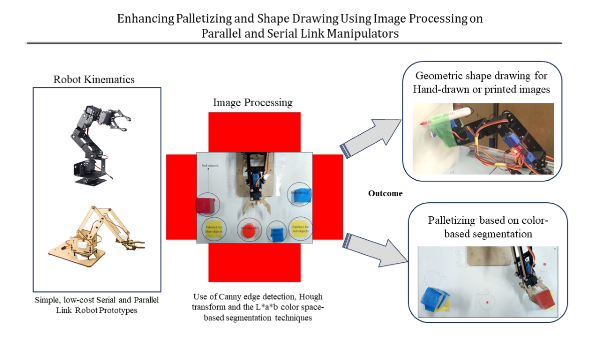
Owing to the nature of the research tasks and the above considerations, the image processing techniques used in this research were color-based segmentation for the palletizing task, and Canny edge detection coupled with Hough transform for the shape drawing task.
Another crucial part of the iterative design process used in realizing and exploring research ideas is prototyping. By practicing rapid prototyping, the advantages that can be realized are shorter development and research conceptualization time, increased quality, reduction in the initial development cost among others[
20]. Cost is a crucial factor in the widespread adoption of any new concept or product and in this case, robotic applications in both academic and industrial applications [
21]. This concept, which was making headlines as early as in the 1990s [
22,
23] is now a reality. While multiple platforms that offer the capability to perform simulations and even integrate virtual reality are available to evaluate on various research constraints, current research still holds that a physical product still supersedes both [
24] The complexity in the design of a comprehensive simulation environment is also a main challenge and current research problem in fully realizing the best experience and software development complexities [
25,
26].
In this paper we present the application of parallel and open-link robots in palletizing and shape drawing tasks respectively based on image processing. While neither the application of image processing in robotics nor robotics control is new, one of the main factors limiting the research in robotics is the two resources of cost and time. This is especially true for small to medium scale industries as well as in the developing countries where very few research institutes or academic institutions have highly equipped robotics centers. This research therefore presents a low-cost method of rapid robotic development. By using low-cost manipulators, less than 100dollars each and utilizing easily available Arduino microcontrollers the cost decreased significantly. The choice of open-source microcontrollers also made it possible to quickly prototype the desired applications. This research paper aims to serve as an easy-to-use guide in learning on the rapid design and development of robotic applications. By presenting both the serial link and parallel link manipulators, each with a different application field based on the structural advantages presented in past research, it can serve as an excellent reference point in the practical application of foundational knowledge in robotics and a testbed for more advanced applications such as the force control [
27] and more precise control operations. This would in turn lead to widespread adoption of robotics and further research knowledge in the field.
2. Manipulator Kinematics
Kinematics is the science of motion that treats the subject without regard to the forces that cause it [
28]. The study of the position, velocity, acceleration, and all higher order derivatives of the position variables (with respect to time or any other variable(s)) is within the science of kinematics. In this regard, manipulator kinematics could either be static, or time-based where the velocities and acceleration are involved. In this research, we considered the position and orientation of the manipulator linkages (forward and inverse kinematics) in static situations [
29].
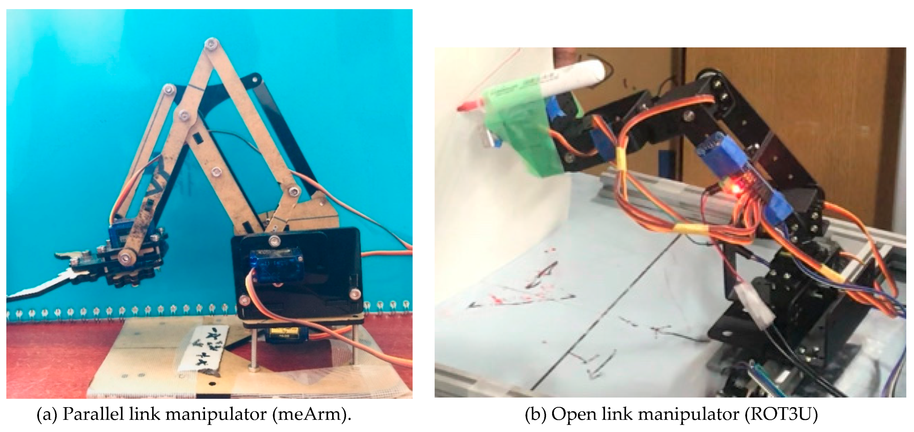
The low-cost robot manipulators used for this research are as shown in
Figure 1.
Figure 1a shows a 3-DoF open-source robot arm that uses four SG90 servomotors including the gripper while
Figure 1b is a 6-DoF aluminum robot arm DIY kit that uses six MG996R servomotors including the gripper. For the shape-drawing application, only 4-DoF were considered as the gripper was not part of the setup.
2.1. Forward Kinematics
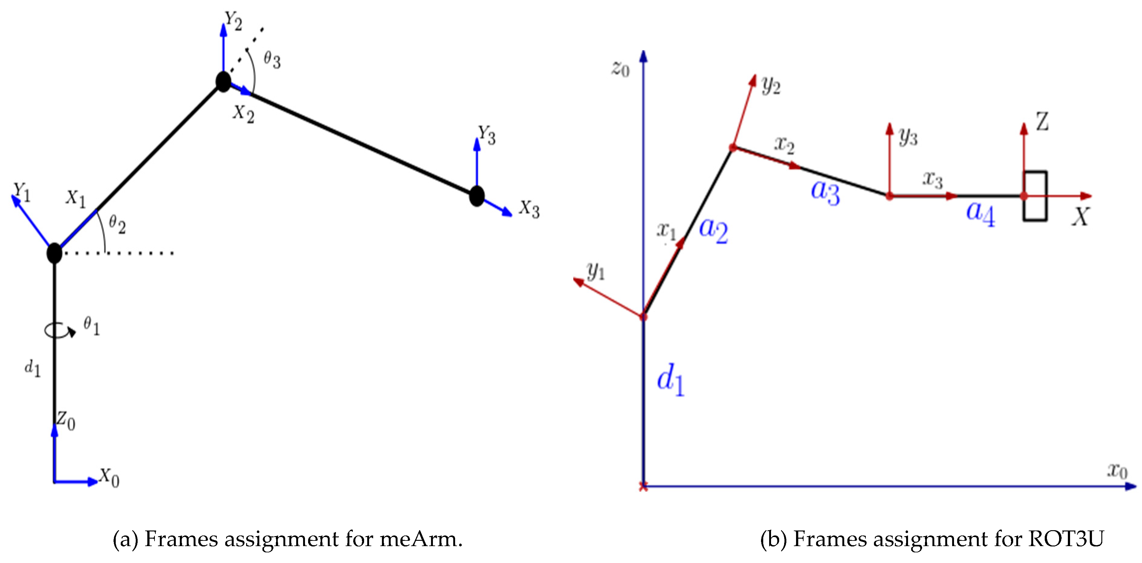
Forward kinematics addresses the problem of computing the position and orientation of the end effector relative to the user’s workstation given the joint angles of the manipulator. According to the DH convention, any robot can be described kinematically by giving the values of four quantities, typically known as the DH parameters, for each link. The link length (a) and the link twist (α) describe the link itself and the remaining two, link offset (d) and the joint angle (θ), describe the link’s connection to a neighboring link. By considering the DH parameter representation in addition to the Euler angle representation, the closed chain manipulator could be expressed as an open-chain equivalent and thus simplifying the derivation of the forward kinematics. Through the considerations above, the robots were decomposed into stationary and moving frames as in
Figure 2a,b.
The DH parameters for the parallel link manipulator (meArm) and the open link manipulator (ROT3U) were obtained as in
Table 1 and
Table 2, respectively.
Consequently, the total homogeneous transformation that specifies how to compute the position and orientation of the end effector frame with respect to the base frame for both manipulators was obtained as follows.
Where the homogeneous transformations of each link were obtained as:
Considering the three links of the meArm, the total homogeneous transformation was obtained as the product of the transformations of each individual link and was evaluated as:
Where the variable
The coordinates (XYZ) of the end effector position are the top right 3x1 matrix of the total homogeneous transformation matrix:
- b.
For the Open link manipulator
The total homogeneous transformation that specifies how to compute the position and orientation of the end effector frame with respect to the base frame was obtained as:
Where the homogeneous transformations of each link were obtained as:
In an equivalent manner to the parallel link manipulator above, the coordinates (XYZ) of the final end-effector position were the top right 3x1 matrix of the total homogeneous transformation
determined as:
Where considering
2.2. Inverse Kinematics
Inverse kinematics addresses the more difficult converse problem of computing the set of joint angles that will place the end effector at a desired position and orientation. It is the computation of the manipulator joint angles given the position and orientation of the end effector [
29]. It involved extracting the Cartesian coordinates of a given position based on the image processing, translating those positions into joint angles and rotating the manipulator servo motor angles to that desired position.
In solving the inverse kinematics problem, the Geometric approach was used to decompose the spatial geometry into several plane-geometry problems based on the sine and the cosine rules.
The determination of the joint angles for both the parallel and open link manipulators was given as:
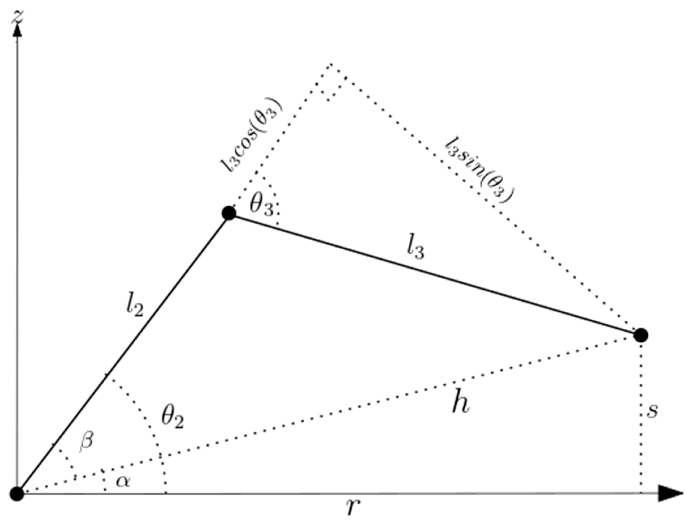
The calculation of the joint angles () for a known position and orientation of the meArm’s end effector was done by considering the trigonometric decomposition of various planes of the manipulator as graphically illustrated below.
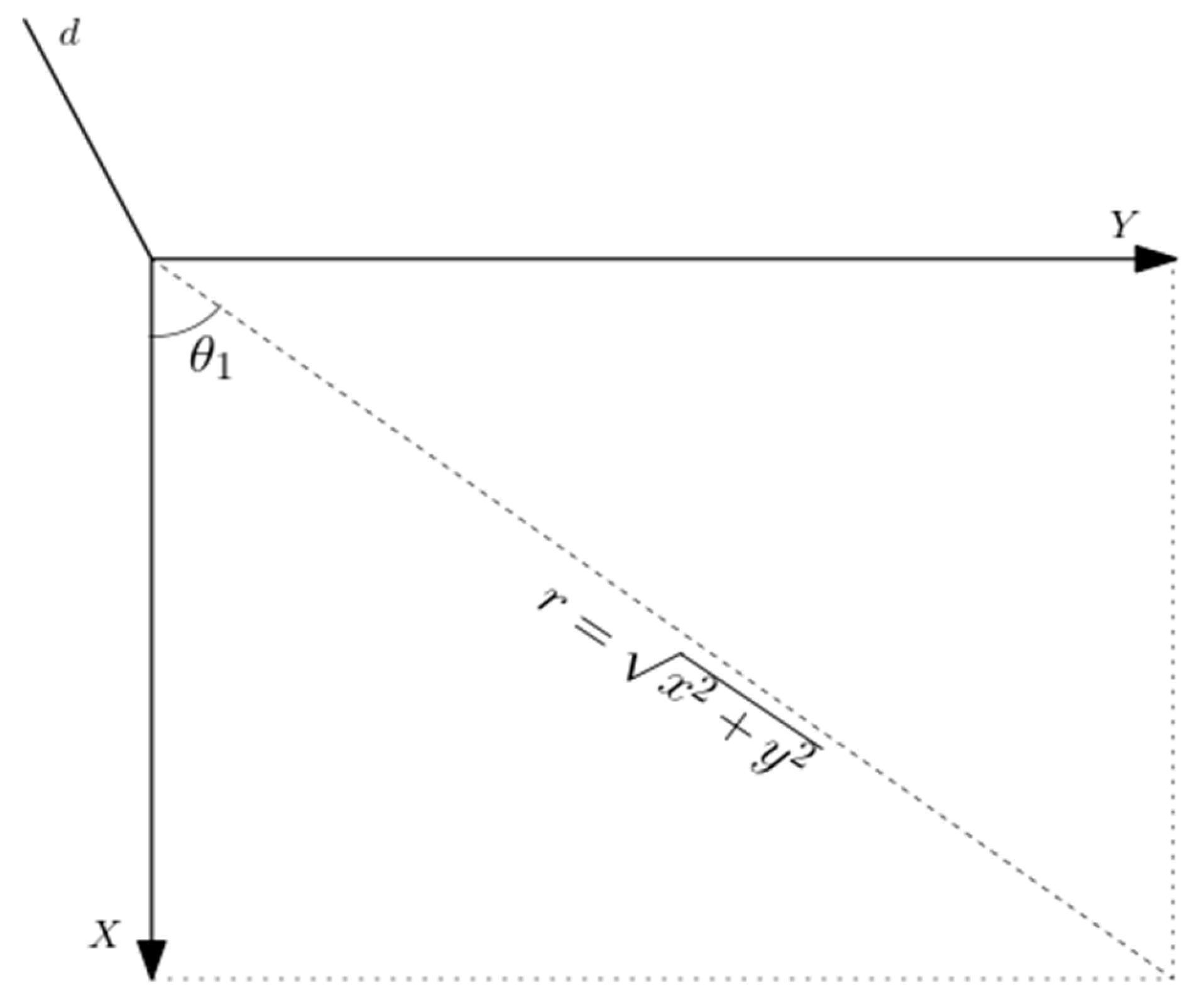
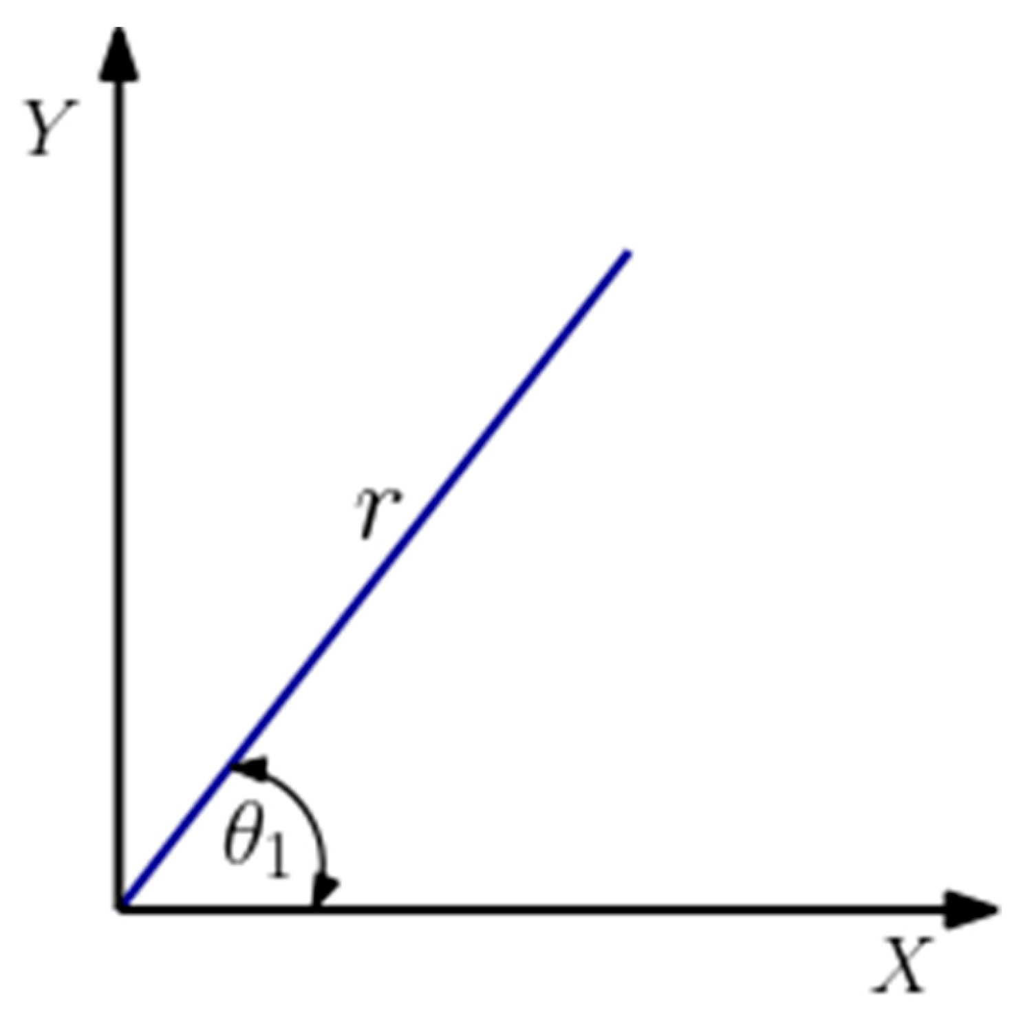
The angle θ
1 was determined by considering
Figure 3 and calculated as:
With the hypotenuse r, connecting x and y obtained using the Pythagoras theorem as:
The angles
were obtained by considering the plane formed by the second and third links as illustrated in
Figure 4.
Where s is the difference between the distance of the end effector from the base and the offset:
- b.
For the open link manipulator
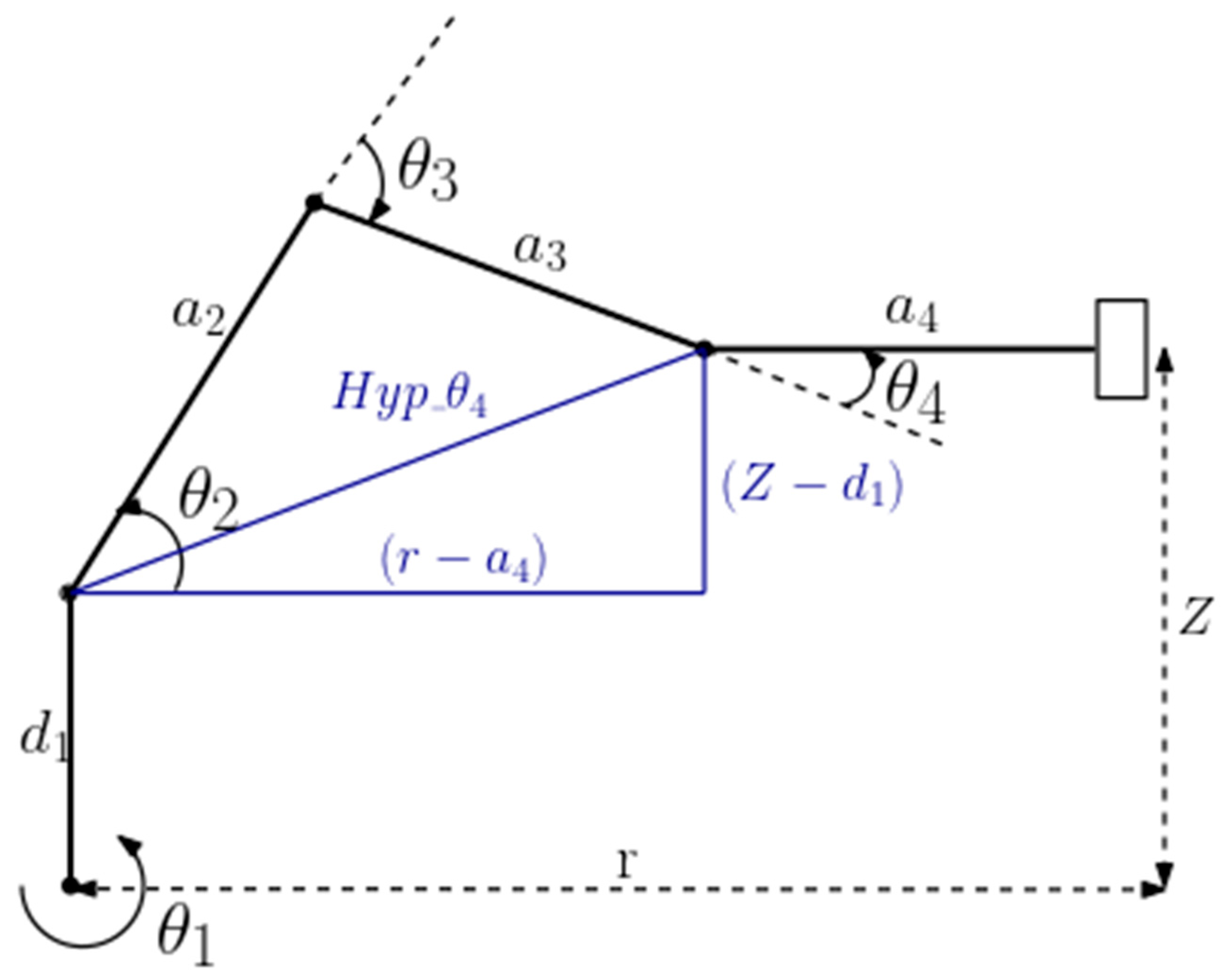
The calculation of the joint angles () for a known position and orientation of the ROT3U’s end effector was done by considering the trigonometric decomposition of various planes of the manipulator as graphically illustrated below.
The angle θ
1 was determined by considering
Figure 5 and calculated as:
The angles
were obtained by considering the plane formed by the second, third and fourth links as illustrated in
Figure 6.
By considering the sine and cosine rules:
Where
is the length directly connecting joint 2 to joint 4 forming the triangle joining link lengths a
2 and a
3 and was determined as follows:
3. Image Processing
Computer vision deals with numerous problems and object recognition is considered one of the highest priorities and has received widespread attention [
30,
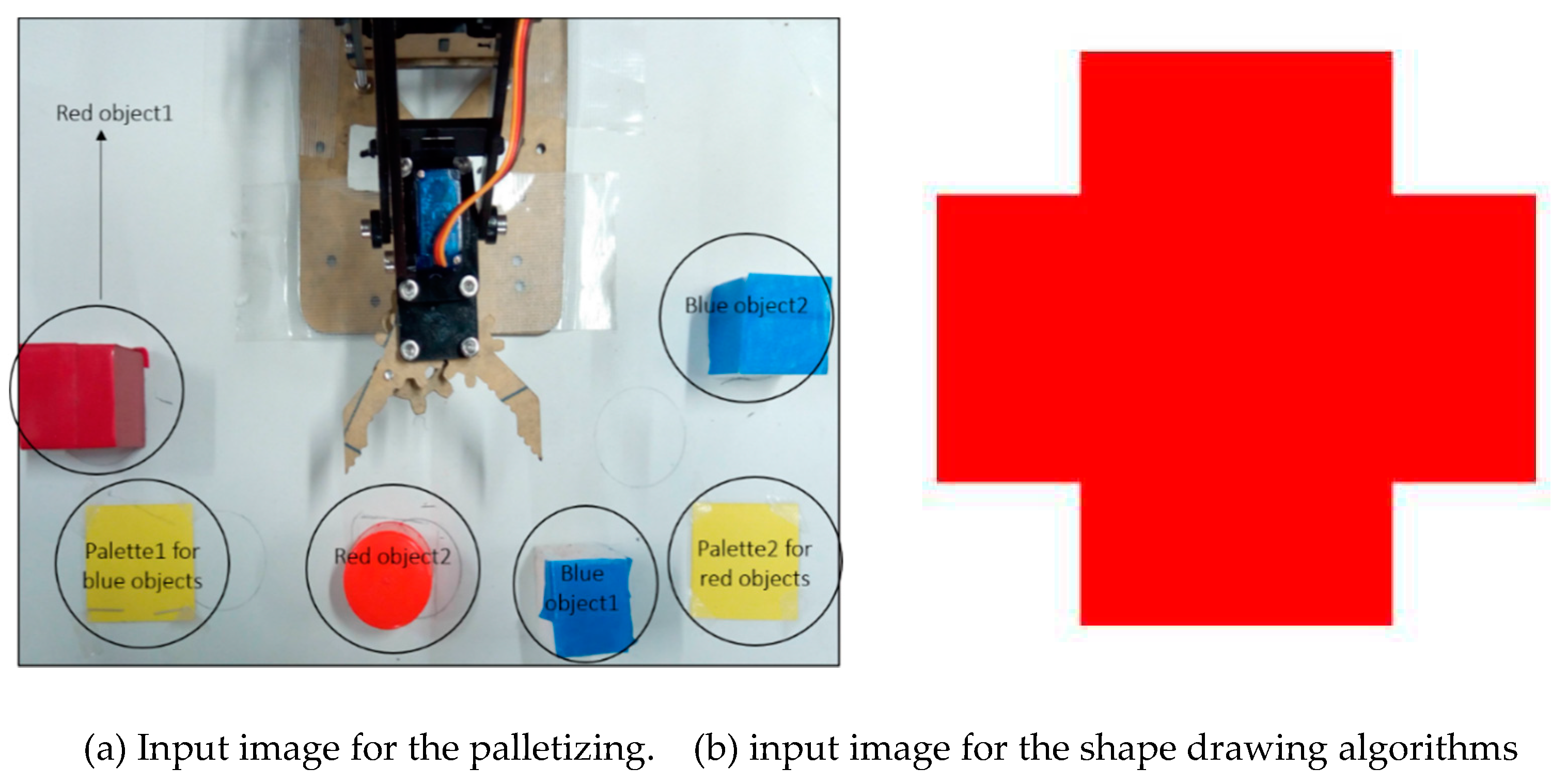
31]. In most applications the research conducted is on the sorting of objects based on color, size or shape. In this research, image processing was employed in both the palletizing and shape drawing tasks to address the problems of detecting an object and determining its location in the workspace. Sample input images to the palletizing and shape drawing algorithms were as shown in
Figure 7.
Image pre-processing techniques were used to improve the image data by suppressing unintended distortions and enhancing the features that were important in the subsequent applications of color-based segmentation in palletizing and edge detection in shape drawing. The following pre-processing techniques sufficed for image enrichment improvement for both robotic tasks:
RGB to Grayscale conversion - This step involved converting a colored image containing the distinct color shades (R, G, B) into a grayscale image which only carries intensity information ranging from black (0) at the weakest intensity to white (255) at the strongest.
Binarizing the image - This process involved converting a grayscale image into a binary image based on a luminance threshold such that all pixels with luminance greater than the threshold were classified as white while those below were black.
Filling the holes in the image - This process helped in accounting for and minimizing noise in the image.
Specific detection algorithms
The result of the pre-processing steps was a binary image in which the regions of interest, that is, the shape to be drawn or the objects to be detected, were clearly defined. As such, further processing techniques for the image segmentation and edge detection were applied to perform palletizing and shape drawing tasks.
The palletizing task involved sorting and stacking objects using color-based segmentation. Color-based segmentation is the process of dividing an image into regions of interest based on their color. A simple, memory efficient yet effective L*a*b* color-based segmentation was used to locate objects with similar color. L*a*b* color space is a color-opponent space with dimension L* for perceptual lightness and a* and b* for the four color-opponent dimensions of human vision: red, green, blue, and yellow [
32], [
33]. The L*a*b* as presented in [
34] can optimize the clustering for image segmentation both in aspects of precision and computation time.
The output of the pre-processing steps was used to identify the objects where logic 1 represented the presence of an object. This information on the location of the objects allowed for subsequent application of color-based segmentation to identify the objects by color on the original RGB image. The L*a*b* color space is designed to approximate human vision and enables one to quantify the visual differences in color [
35]. In this task, it was used to account for variation in color value of the RGB image across a detected object caused by problems such as camera noise. For each detected object, an average color in a*b* space was calculated, such that each detected object had a single value of ‘a*’ and ‘b*’ for all its pixels.
Since each detected object now had an 'a*' and 'b*' value, it could be classified by calculating the Euclidean distance between its pixels and a predefined color marker. The predefined color markers were a set of 'a*' and 'b*' values for standard Red, Blue, Green and Yellow colors. These were the reference colors against which an object’s color value was compared. As such the Euclidean distance d between each pixel and a corresponding marker was computed as:
The smallest distance indicated that a pixel most closely matched a corresponding color marker. Subsequently, by the nearest neighbor rule, if for instance the distance between a pixel and the red color marker is the smallest, then the pixel would be labelled as a red pixel and its corresponding object would be classified as red.
The last step of this algorithm involved determining the centroid locations of the segmented objects in pixels and then mapping them to the real-world manipulator’s workspace using a suitable mapping function.
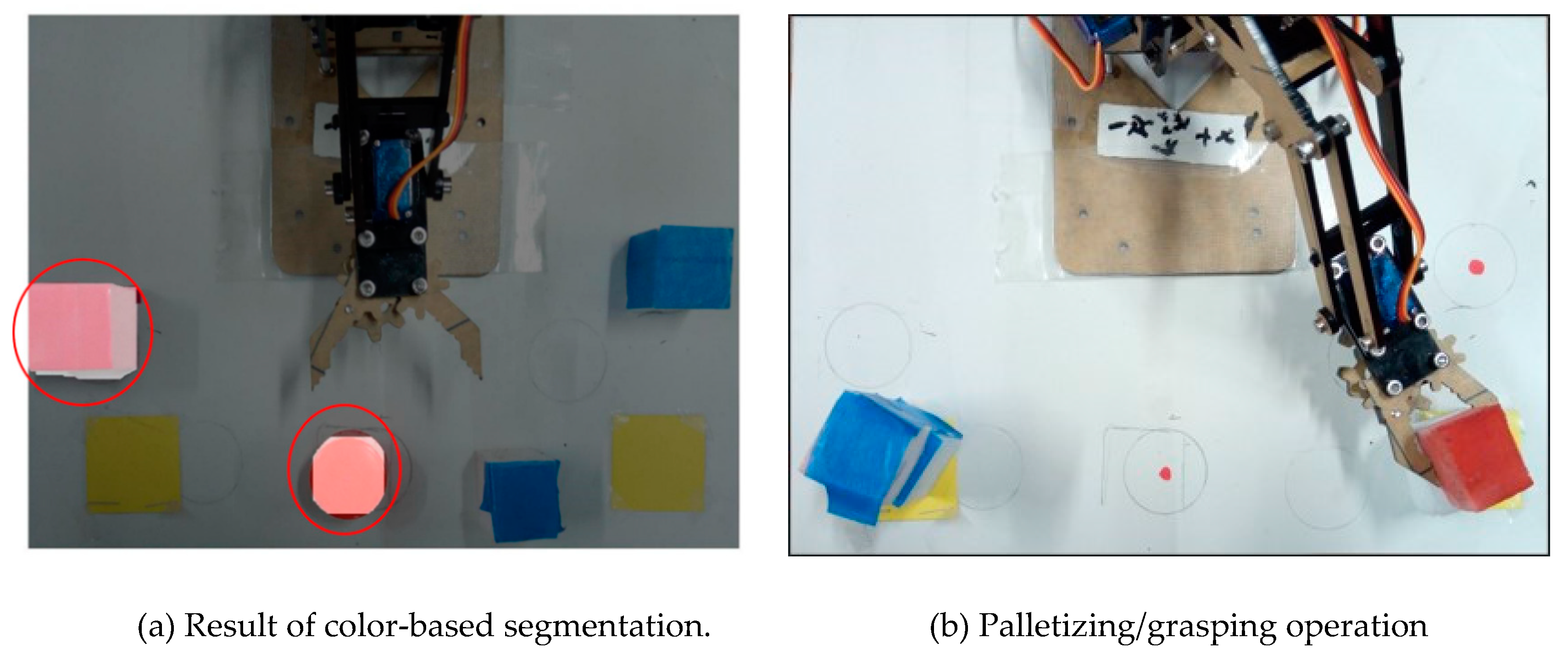
Figure 8a shows two objects detected as ‘red’ since their average a*b* values closely matched those of a predefined red color marker.
Figure 8b shows the result of detecting the red and blue objects, obtaining their real-world coordinates in the workspace and finally applying inverse kinematics to sort and stack them on their respective pallets.
- ii.
Canny edge and Hough transform for shape drawing.
In the implementation of the geometric shape drawing, the input image which was either taken using a camera for a hand-drawn image or digitally drawn by the user was supplied to the robot. The image was in the form of an array of pixels, while the drawing manipulator required a set of points in the Cartesian space, convertible into a joint space [
36]. In this study, the edge detection method was employed in the determination of the shape outline based on the input image. Following the shape outline, the pixel locations could be obtained on the image, mapped on to the corresponding workspace coordinates and the robotic manipulator could then draw the determined shape.
Edge detection is an image processing technique used to identify the boundaries of objects within images. This is by detecting discontinuities in color and brightness. Considering an image, an edge is a curve that follows a path of rapid change in image intensity and is often associated with the boundaries of objects in a scene. The Canny edge method which is a powerful edge detection method that is relatively simple and more likely to detect true weak edges was used in determining these boundaries[
37], [
38]. This detection of the boundaries of the input shape was achieved by selecting a suitable threshold based on the color intensity of the preprocessed input image.
On detecting the shape boundaries, the Standard Hough Transform, which is a feature extraction technique was used to identify the Hough peaks which are the potential lines in the image. The Hough lines function then finds the endpoints of the line segments corresponding to peaks in the Hough transform and fills in small gaps in the line segments [
39]. The identified endpoints give the start and end points of line and thus a full identification of the shape based on the detected boundaries [
40]. The identification of the shapes based on the detected boundaries was the same for both the hand-drawn and digital image. One of the main considerations in the detection based on the Hough peaks was the thickness of the line where adjusting the threshold varied the sensitivity to line thickness [
41].
Once the lines on the shape had been identified, the reconstruction of the geometric shape was done by sorting the obtained endpoints for a particular line and its connected neighboring line. As a last step to the image processing, the sorted endpoints pixel locations on the image were then mapped on to the manipulator workspace. Using these points, the shape could then be drawn out by the robotic manipulator.
For the input image shown in
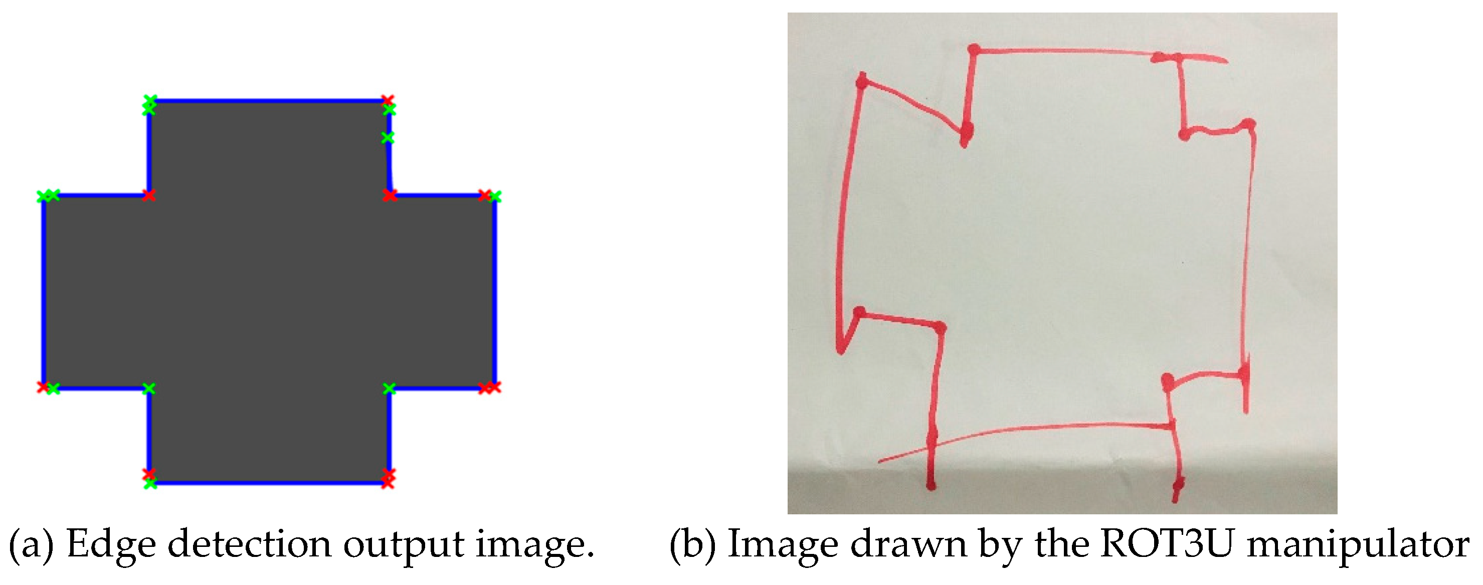
Figure 7b, the application of Canny edge detection technique using Hough transform in the determination of the endpoints in the detected lines resulted in the image shown in
Figure 9a. From this, all the lines constituting the shape were identified and an outline of the shape obtained. As the final step of the geometric shape algorithm, the image in
Figure 9b was outlined by the open link manipulator (ROT3U) after the mapping and inverse kinematics of the identified endpoints.
