Preprint
Article

Hydraulic Performance Optimization of a Submersible Drainage Pump

Altmetrics

Downloads

122

Views

34

Comments

0

A peer-reviewed article of this preprint also exists.

Submitted:

22 November 2023

Posted:

22 November 2023

You are already at the latest version

Alerts
Abstract
Small submersible drainage pumps discharge leaking water and rainwater in buildings. In an emergency (e.g., heavy rain or accident), monitoring the flow rate in advance is necessary to enable optimal operation, considering the point where the pump operates abnormally when the water level increases rapidly. In another, pump performance optimization is crucial for energy saving policy. Therefore, it is necessary to meet the challenges of submersible pump systems, including sustainability and pump efficiency. The final goal of this study is to develop an energy-saving, high-efficiency submersible drainage pump capable of responding to emergencies. In particular, this paper targeted the hydraulic performance improvement of a submersible drainage pump model. Before the development of driving mode-related technology capable of emergency response, we first tried to find a way to improve the performance characteristics of the existing submersible drainage pump. Rather than designing a new pump, we disassembled the current pump and reverse engineering. Then, numerical simulation was performed to analyze the flow characteristics and efficiency of the pump. Then, the pump test was carried out to obtain the performance and validated with numerical results. Results revealed that changing the cross-sectional shape of the impeller reduced the flow separation and enhanced velocity and pressure distributions. Also, it reduced the power and increased efficiency. Results also showed that the pump's efficiency increased to 5.56% at a discharge rate of 0.17 m3/min, and overall average efficiency increased to 6.53%. In addition, the submersible pump design method could be suitable for the optimized pump's impeller and casing numerically. This paper can provide insight and information on the design optimization of pumps.
Keywords: 
Subject: Engineering  -   Mechanical Engineering

1. Introduction

This study relates to the performance improvement of the submersible drainage pumps. Submersible drainage pumps are divided into large submersible pumps used for drainage (rainwater) pumping stations and small submersible pumps applied to the buildings. Small submersible drainage pumps are used for draining from buildings when leakage and rainwater flow into the basement [1,2,3]. The TRL (Technology Readiness Level) for submersible drainage pumps is 7-9, and it is a situation where no unique technology can come out. Existing technology patents also utilize technology content used in other fields. According to the patent acquisition, vibration sensors are installed on the pump shaft to solve the blocking phenomenon caused by foreign substances and vibration problems also caused by cavitation, etc., or the shape of the impeller changes without considering the performance to prevent clogging of foreign substances or improve the existing monitoring technologies. Pump efficiency is a significant energy-saving policy factor [4,5]. If pump efficiency increases, energy will be saved significantly.
Due to the complicated implicit relation between the hydraulic performance and the complex geometry shape of impeller passages, the study of optimization and the inverse problem of the submersible pump moves slowly [6,7]. Shi et al. [8] started to design a new submersible pump for deep wells with the CFD technique. They achieved a sufficient pump efficiency than the traditional pumps. Zhu et al. [9] investigated a mechanistic model for improving the system performance with the gas-liquid flow in a submersible pump. Manivannan A. [10] conducted a study on the computational fluid dynamics of a mixed flow pump to predict the flow pattern inside the impeller. he different parameters and optimization techniques were used to obtain optimal output for the pump impeller numerically [11]. The pump impeller head was optimized using various optimization algorithms and reduced frictional loss of the pump [12]. Using an inverse design, Zangeneth et al. [13] investigated a mixed-flow pump for suppressing secondary flows. Henceforth, they [14] performed an experimental study for the validity of the model pump. Kim et al. [15] studied improving suction performance and efficiency by optimizing a mixed flow pump by CFD. The authors [16] also studied the suction performance improvement of mixed-flow pumps. The result exhibited that the specific speed and shape of the pump's impeller greatly influence suction performance.
Yan et al. [17] investigated the CFD-based pump redesign of a centrifugal to improve efficiency and decrease unsteady radial forces. CFD method was applied to study the effect of the volute and the number of impeller blades and trailing-edge modification of pumps [18,19]. Qian et al. [20] adopted the Plackett-Buram test design method for performance optimization of multistage centrifugal pumps. Results significantly impacted the pump's axial force and hydraulic performance when considering blade exit angle, outlet diameter, blade wrap angle, etc. Liu et al. [21] also studied the RBF neural network and particle swarm optimization method to improve the performance of submersible well pumps. Results found that the pressure gradient in the impeller was increased, and the pressure amplitude of the impeller was significantly reduced. Ling Bai et al. [22] highlighted the performance improvement of the EPS impeller based on the Taguchi approach, and the result found that the front and rear shroud of the impeller meridian significantly affects the ESP performance. Chen et al. [23] studied performance improvement based on the entropy production method of a mixed-flow pump. Results found that the geometric and hydrodynamic parameters greatly influenced the pump's energy characteristics. Suh et al. [24] optimized the impeller and suction performance to increase the hydraulic efficiency of a mixed-flow pump. Jeon et al. [25] conducted a study on a regenerative pump impeller and enhanced the model’s efficiency by numerical simulation and design of experiments (DoE). Siddique et al. [26] investigated the impeller design optimization of a centrifugal pump by numerically enhancing the pump head and significantly reducing the input power. Shim et al. [27] presented a study on enhancement flow recirculation and cavitation of a centrifugal pump by controlling the meridional profile of the blade. Yang et al. [28] investigated multistage ESP to improve hydraulic performance using the Taguchi optimization method. The Taguchi method was a remarkable handy tool in optimizing the ESP. Arocena et al. [29] designed and analyzed the intake structure of a submersible pump numerically. Wei et al. [30] investigated the influence of impeller gap drainage width on the performance of a low-specific-speed centrifugal pump, and the results revealed that using a smaller gap width could significantly improve the performance. Han et al. [31] presented the influence of various impeller blade outlet angles on the performance of a high-speed ESP using experimental and computational methods. It was found that the impeller vane exit angle had a significant effect on the pump performance curve. Tong et al. [32] investigated axial flow pump performance analysis experimentally and numerically. Results showed that the higher head was encountered with increased pump rotating speed. Fakher et al. [33] studied the efficiency improvement of an electric submersible pump. They replaced a permanent magnetic motor instead of a conventional one for a prolonged ESP mean failure. The flow patterns inside an electrical submersible pump are presented using CFD and compared with visualization experiments [34]. However, the study did not show that optimizing the shape change of the pump casing and impeller improves the hydraulic performance in a single-stage submersible drainage pump.
This study adopted a centrifugal-type submersible drainage pump used in buildings as a development target. The main research content is not to develop a new submersible pump but to analyze the performance of existing submersible pumps through simulation and experiments, to design the shape to enhance the performance of significant parts, manufacture parts, and conduct the pump tests using 3D printing technology. In addition, primary research contents are patented based on the developed technology.

2. Materials and Methods

2.1. Pump Dimensions and 3D model

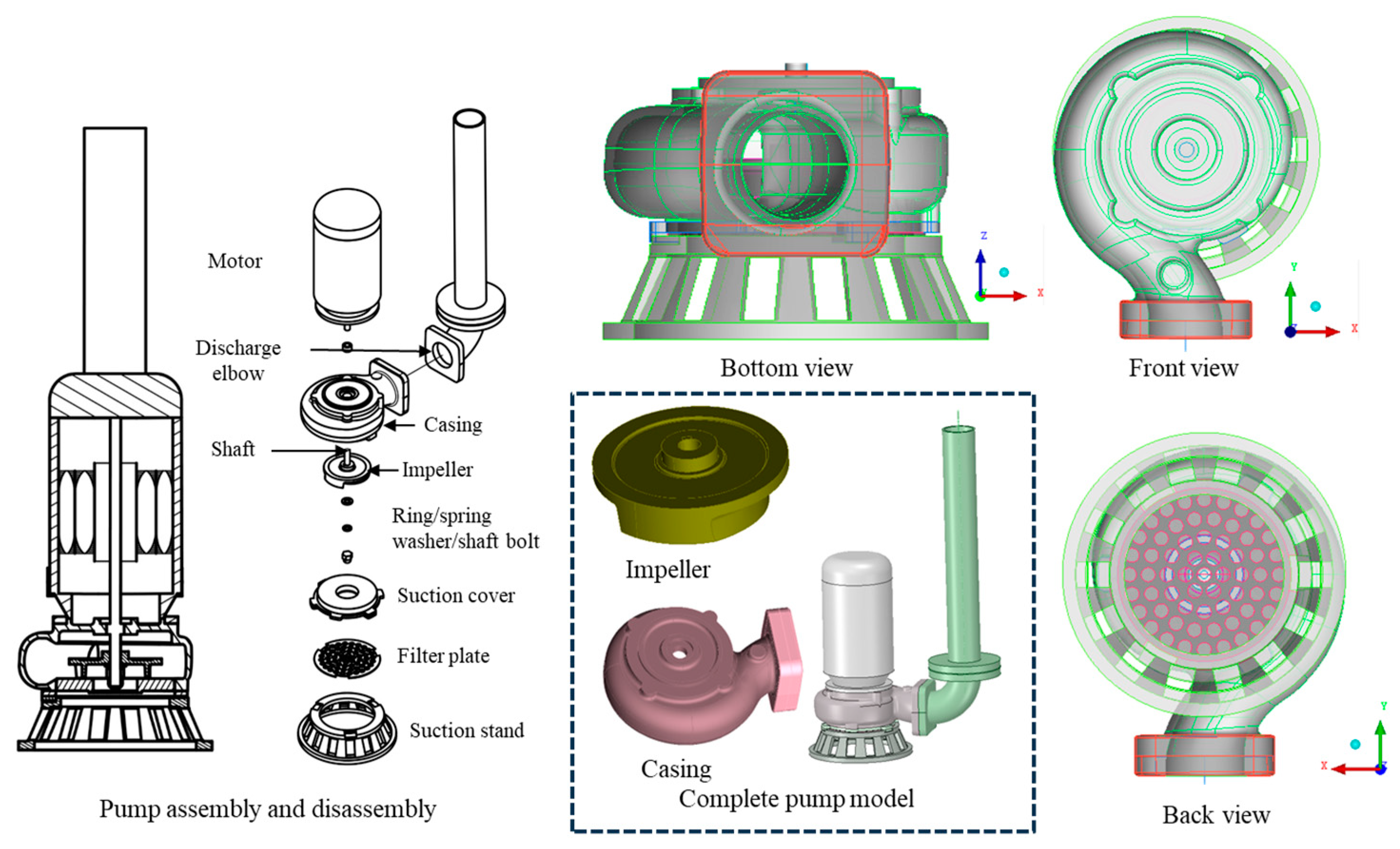
Three-dimensional scanning was performed to accurately obtain the dimensions of the pump casing and impeller to be analyzed. For this purpose, the DWE-08B submersible drainage pump was disassembled, as shown in Figure 1. The exact dimensions of the pump are required for analysis through computational methods. Of the pump components, only the significant parts of the pump impeller and casing were scanned using a noncontact portable 3D scanner (Creaform 50 with a tolerance of 1/100). They generated the three-dimensional geometrical shape and imported it to CAD software for cleaning.
This study used ANSYS-ICEM commercial software to clean scanned 3D geometry and create as .STP file. Figure 2 shows an assembly and disassembly drawing of the vertical semi-open type submersible pump (model- DWE-08B). Figure 3 illustrates the cross-sectional view of the critical components of the pump. Table 1 presents the major design dimensions of the pump impeller and the casing obtained from the pump company's catalog.
Table 1. Original submersible pump model (DWE-08B) design parameters.
Description Power Flow rate Head Impeller Casing
Blades D1 D2 Flow path height Inlet height Outlet dia.
Model H.P. m3/min m No. mm mm mm mm mm
DWE-08B 1 0.16 10 2 25 105 54 135 60

2.2. Specifications of the Submersible Pump

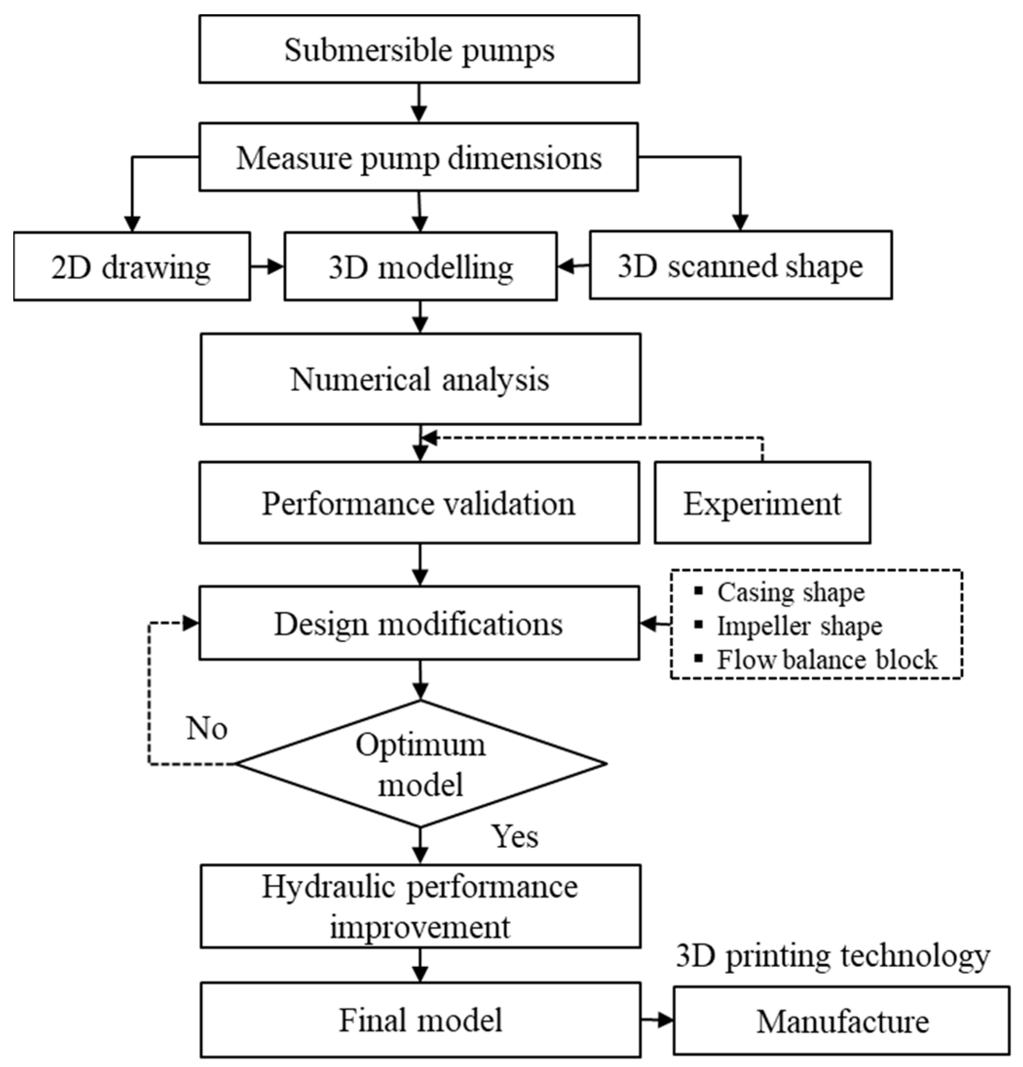
The pump company provided us with only the major pump specifications. Figure 4 illustrates the various pump's model performance curves. DWE-08B model performance data of the pump's model is represented in the black turn highlighted with a circle and red line. Table 2 shows the submersible pump's data presented in the pump company catalog [2]. From the record, we used these data to figure out the specific point of the pump to be analyzed in this study. Figure 5 illustrates the hydraulic performance optimization procedure.

2.3. Computational Domain and Boundary Conditions

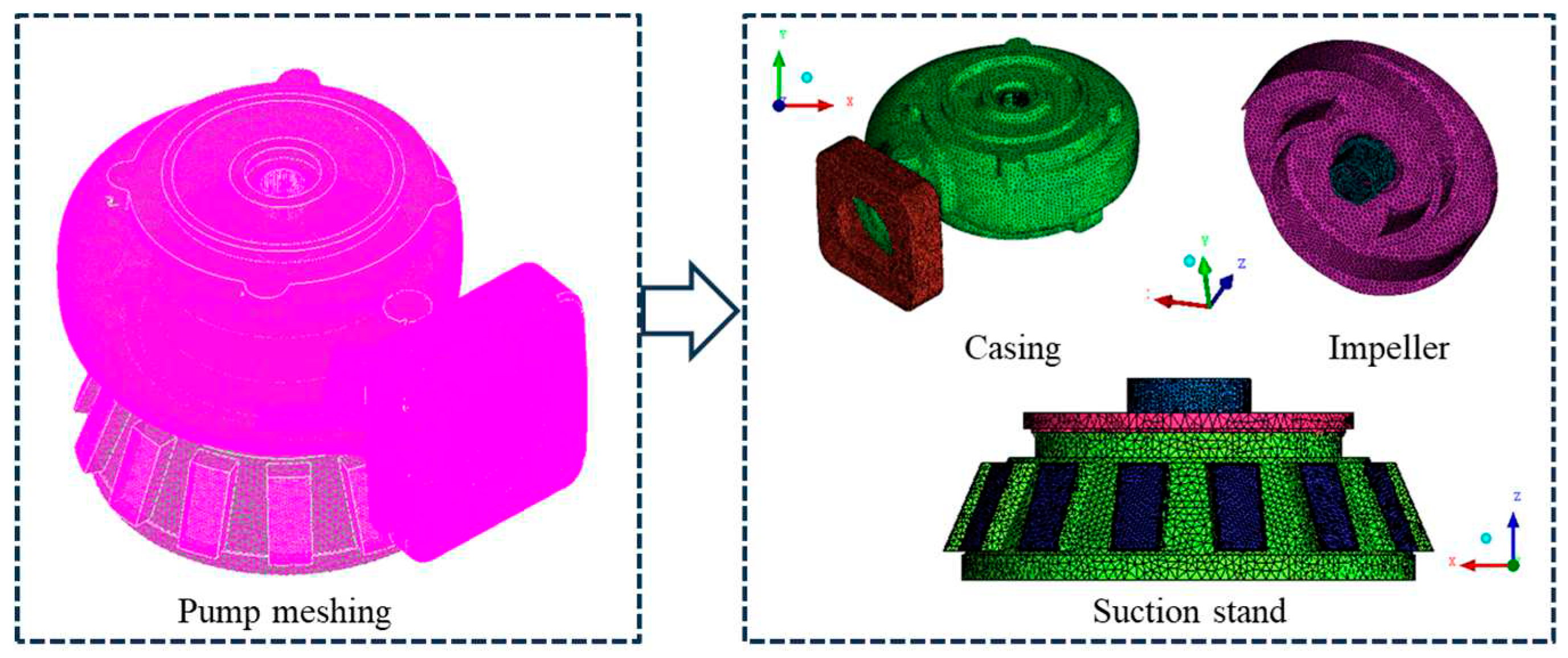
This study created unconstructed tetrahedral meshing grids. Figure 6 illustrates a submersible pump meshing grid. Changing the number of meshing grids confirms the grid dependency [35]. The total meshed grids were 272,563 nodes and 1,374,829 elements, respectively. The continuity and momentum equations apply to Reynolds Average Navier-Stokes (RANS) equations for calculating the numerical flow analysis of the pump [36,37]. The SST model considers calculating the turbulent shear stress [37,38]. The ANSYS ICEM-CFX software (21R2, ANSYS Inc., Canonsburg, PA, USA, 2021) is utilized for grid generation and analysis of the pump. In this work, the boundary conditions used for the simulation were mass flow rate as the inlet and 0 Pa as the pressure outlet.
All boundary walls were assumed to be smooth walls with no-slip conditions. The frozen rotor selects at a specific rotational speed for steady-state, incompressible flow analysis in the rotating and steady. Figure 7 gives the boundary conditions for numerical analysis of the DWE-08 pump domain. The velocity and pressure residual value was 1x 10⁻⁵, controlled by convergence criteria.
Table 1. Meshing grids of the DWE-08 submersible pump.
Description Elements Nodes
Model 1 272,563 1,374,829
Model 2 532,924 2,733,319
Model 3 1,085,683 5,648,730

3. Results and Discussion

Section 3.1 provides the pump performance validation of the computed data. Section 3.2 describes the performance analysis of the submersible pump at different operating conditions. Also, design modifications of the casing and impeller are illustrated in Section 3.3. Moreover, Section 3.4 presents the pump's hydraulic performance improvement and optimum model.

3.1. Verification of the Numerical Result

An experimental setup was constructed to compare with the computed data to verify the reliability of the test pump—the test facility employed to meet the KSB 6321 and ISO 5198 standards [39,40]. The measurement sensors used in the test pump to obtain the test data allowed a standard deviation of ±2%. The test environmental working fluid temperature and relative humidity were 13±1 °C and 32±5 %.
The hydraulic performance parameters such as head, volume flow rate, power and efficiency are sufficient for comparing the measurement and calculated data. The equations for pump head, energy, and efficiency are expressed as:
H = p 2 p 1 ρ g + V 2 2 V 1 2 2 g + z 2 z 1
P = ω T
η = ρ g Q H ω T
where H represents the pump head in m, p is the static pressure of the pump in N/m2, V is the velocity of the pump in m/s, z is the elevation of the pump in m, P is the shaft power in kW, Q is the volumetric flow rate in m3/min, ω is the rotational speed in rad/s, T is the toque in N·m, ρ is the working fluid density in kg/m3, and g is the gravitational acceleration in m/s2, respectively. Subscripts 1 and 2 denote the inlet and outlet of the pump.
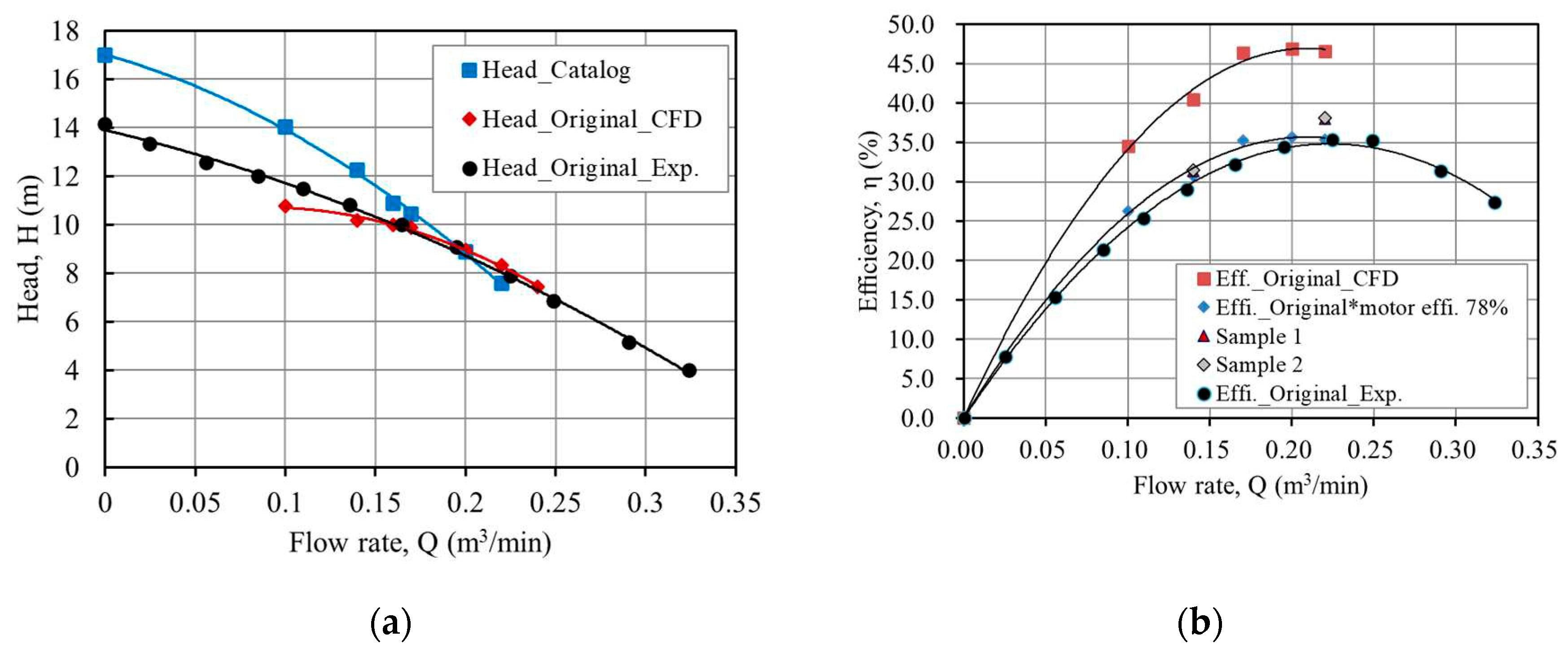
Figure 8 presents the experimental measurement data tested by the KTC (Korea Testing Certification Institute) at the pump test facility center. If we look into the test results in Figure 8, when the flow-specific point (volumetric flow rate) was 0.165 m3/min, the total head was 10 m, and the overall efficiency was only 32.14%, which was not the same as the pump efficiency. Because the test pump was in the water and could not measure the torque, it must regard the motor's power factor (0.78) to compare it with the experimental results. In addition, the catalog's performance data, test data, and analysis data were all presented for each outcome. When comparing all matters, the average head error value was only 0.0456%, the power average error was only 0.0808%, and the efficiency average error was only 0.0617%. The head and efficiency differences were only 0.07% and 10.18% at the design flow rate. The lower difference was observed at the higher flow rate of the pump. The standard deviation of the pump head was 0.046%, power was 0.0047%, and rotational speed was 1.54%. At 95% confidence limit, the normal distribution of the test pump was measured, and the uncertainty of the pump head was H ± 0.00989 m, discharge rate was Q ± 0.00178 m3/min, the power was P ± 0.0102 kW, and the rotational speed was N ± 3.298 rpm, respectively.
First, looking at Figure 8(a), there is a clear difference between the test and catalog results. As observed from the H-Q curve, the analysis results agreed relatively well with the experimental data except for the low flow rate. The two results did not match well in the low-flow region due to the influence of the grid and y+. Therefore, it is desirable to exclude or modify the catalog data. To compare this with the test value, it shows that the test result is well-matched when considering the motor power factor of 0.78, as mentioned in the shaft power. Samples 1 and 2 values in Figure 8(b) are the efficiencies mentioned in the high-efficiency energy equipment report. Moreover, in this study, the mechanical losses were not taken into consideration of the submersible pump in the numerical analysis.

3.2. Performance Analysis

Also, this study analyzed the pump inside flow pattern and velocity distributions at a design flow rate. Figure 9 shows the velocity vectors and velocity streamline distribution of the pump. As observed, the flow recirculates at the pump discharge region where the energy dissipates, resulting in significant pump losses. The flow separation in the casing caused relatively large vortices at the outlet of the pump casing. Also, the clearance gap between the pump volute and impeller was large (more than 2 mm). This clearance gap flow also creates vortices that separate from the impeller blade and reduce local pressure. Also, the impeller is located in the casing at the bottom of the pump, as shown in Figure 10. Henceforth, changing the impeller's center further reduces the pump's efficiency. Therefore, it needs a CFD-based design modification study and behavior of the flow in various geometries to enhance the pump performance.
Based on the experiment and simulation results, the study determined that there existed a possibility of increasing the efficiency by considering using an efficient pump motor and designing or shaping the part where the loss appears. The use of an efficient pump motor was outside the scope of this study; this study examines the cause of the decrease in efficiency and finds a way to supplement the design of the pump components. It noted that, from the loss analysis of the pump, the mechanical loss, the ratio of impeller loss and casing, and inlet loss are also high [41]. The efficiency of the DWE-08B pump is 30% to 40%, which is not an optimal performance condition. Of course, since the impeller is a semi-open type, it is less efficient than the closed type, but the efficiency is comparatively low compared to other pumps. Therefore, this study considered improving the efficiency to be the optimal design of the impeller and casing, suggesting improvements in the geometry of the two components.

3.3. Design Modifications of the Casing and Impeller

In this study, two shapes that can reduce the large gap at the upper of the pump impeller were proposed and analyzed to optimize the shape of the casing. Model 1 was created with the reduced flow path from the original model; Model 2 was created with the cochlear (tubular) flow passage in the casing intact. Figure 11 shows the casing shape changed model.
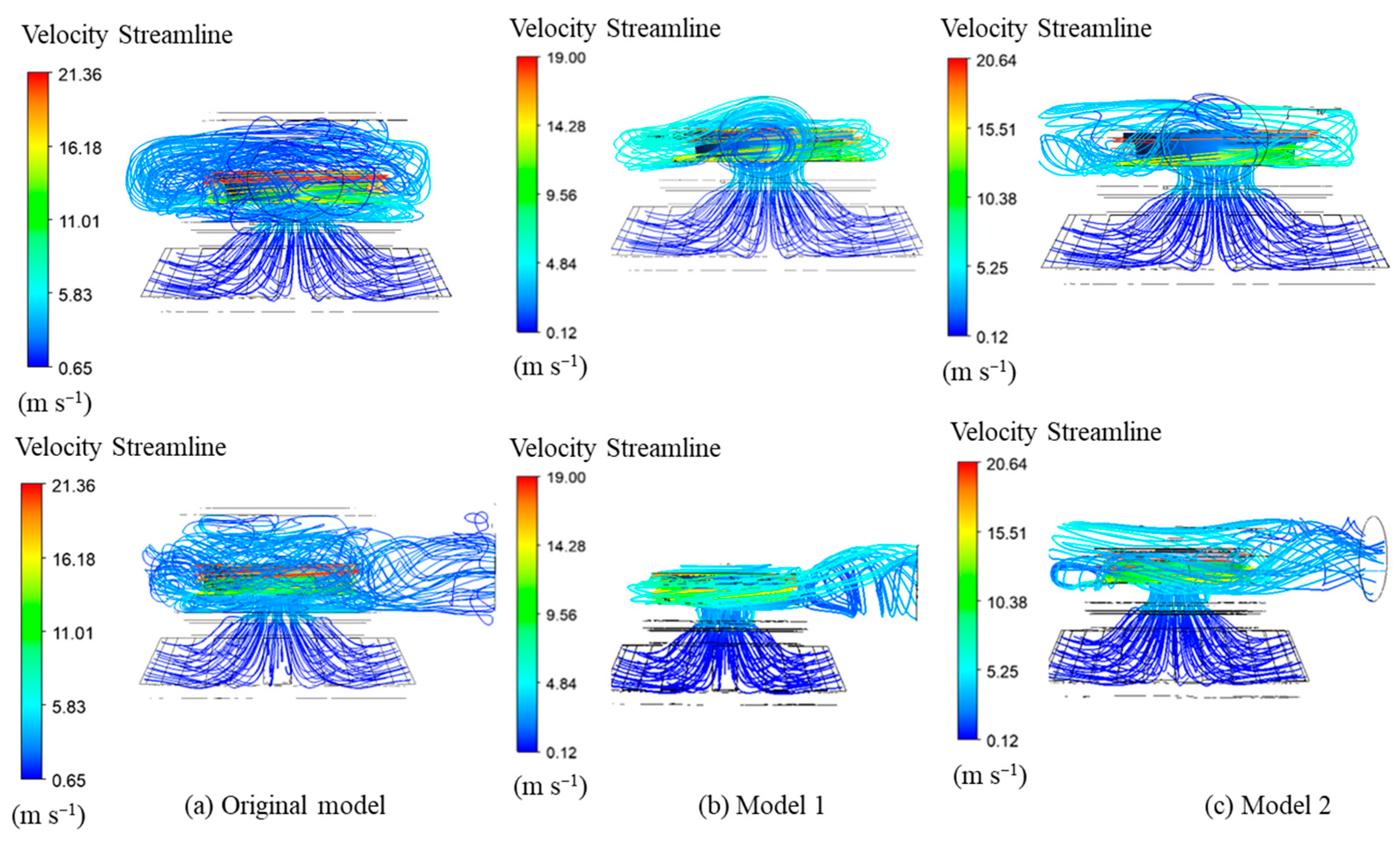
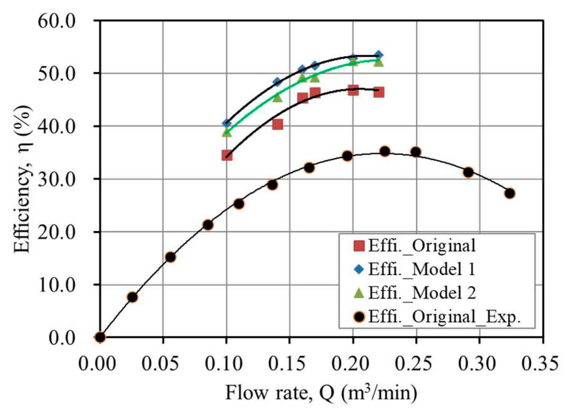
Figure 12 displays the comparison of velocity streamlines for the casing shape-changed model. As shown in Figure 12, the fluid flow is formed in a streamlined shape, eliminating the idle space at the top; the fluid flow at the outlet of the pump casing is discharged without swirling using a guide rib. Figure 13 shows the performance comparison for the casing shape change model. Table 4 presents the pump efficiency according to casing shape change models. By changing the casing shape, it is observed that the relative efficiency is improved up to 4% ~ 5%.
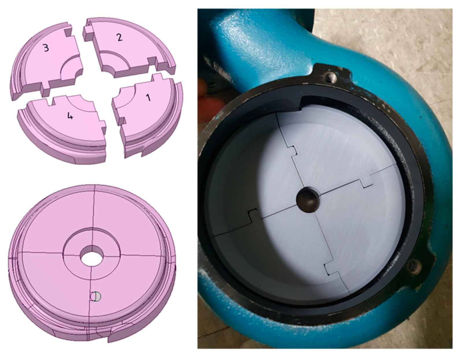
However, it is difficult to make a new one with die and casting; therefore, an in-depth investigation is a prerequisite for optimization. Then, it applied the optimization plan of the casing shape to prevent the need for wood-shaped and casting work. A method involves attaching a simple installable member to the pump casing to reduce the space. Optimizing the casing shape utilizes an approach of changing the casing shape using a flow balance block (FBB), which can easily be installed. It employed the FBB instead of the casing shape change model. Figure 14 shows the flow balance block model. The study utilizes the FBB to reduce secondary and friction losses where the flow in the casing is stagnant.
Also, this study modified the three different shapes of the impeller. Impeller 1 vanes were created diagonal (obliquely line) in the basic model. Impeller 2 was an extended tip from the Impeller model 1. Impeller model 3 vanes were made thicker vanes from the basic model. Figure 15 shows the impeller shape change model. The impeller shape change made the shape of the vane inclined to improve the flow in front of the rear shroud. After that, this pump simulation data compared the performance characteristics of the different impeller shapes to improve efficiency with the original model.
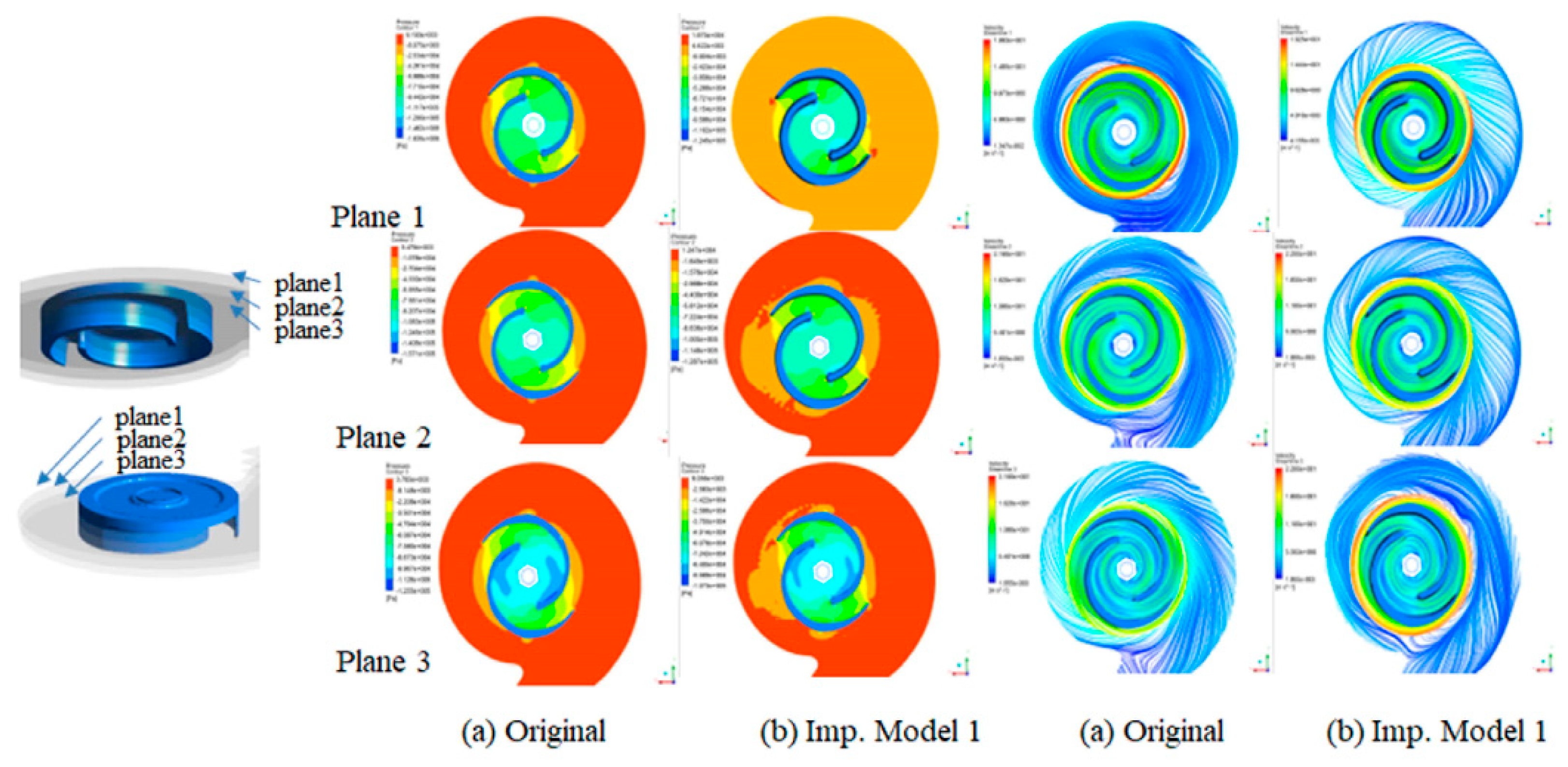
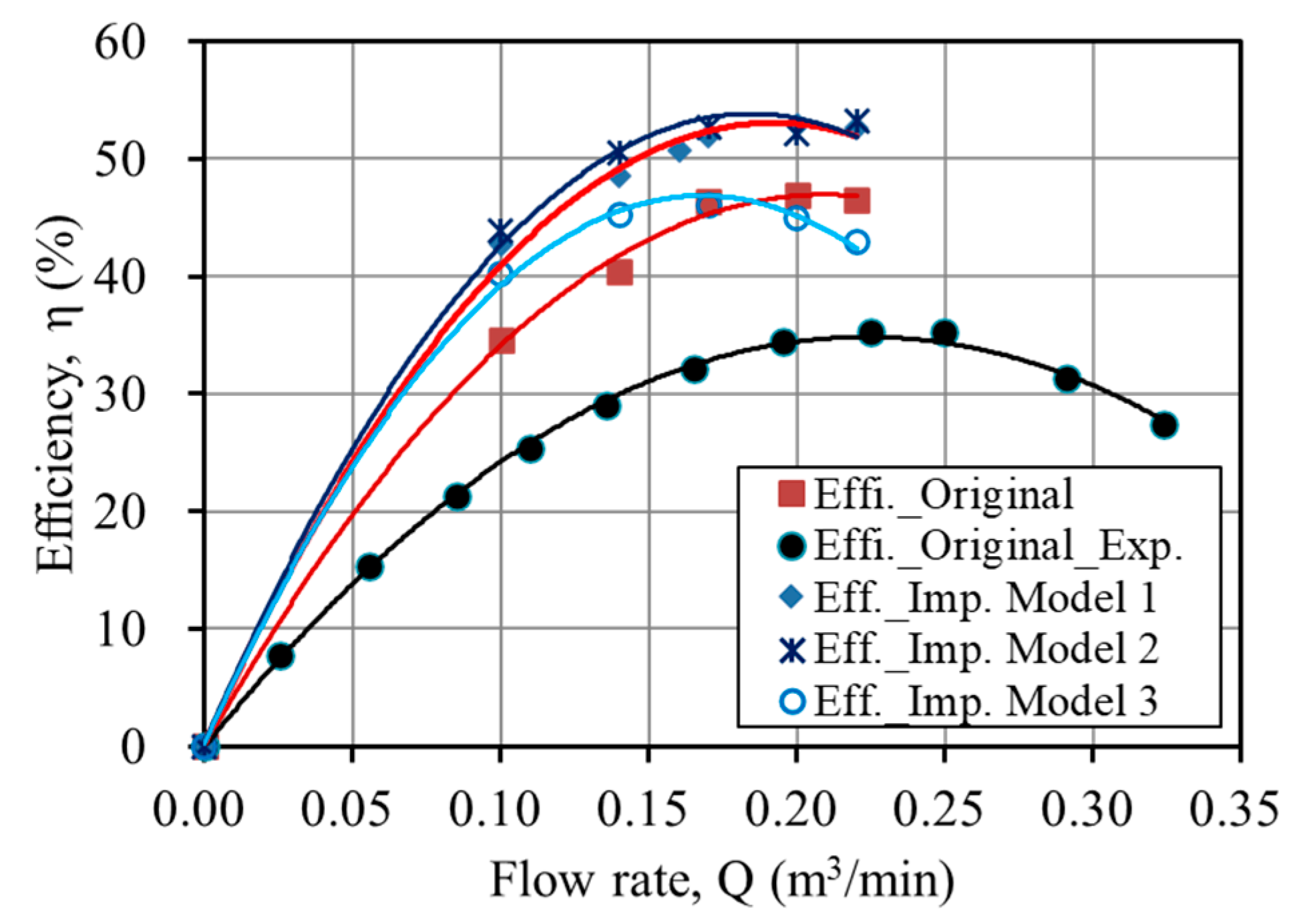
Furthermore, Figure 16 illustrates the pressure and velocity streamline distribution in other planes of the pump impeller. As observed, it could reduce the flow losses by improving the streamline in the lower area (planes 1, 2) according to the change of the impeller shape. Figure 17 shows the performance comparison according to various impeller shape change models. The result shows that changing the shape of the impeller increased the pump efficiency. Hence, according to the evolution of the impeller shape, reducing the shaft power and increasing the efficiency to 5.56% by preventing flow disturbance. Therefore, this study considered the impeller shape change model 1 optimal for manufacture.

3.4. Optimum model

The existing model's performance analysis and modification of the casing and impeller were reviewed. This study examined the flow around the impeller of the current model and devised a strategy to increase efficiency. The pump efficiency significantly increased to 49.30% by modifying the casing shape at a 0.17 m3/min flow rate, less than 2.64% of the modified impeller. Also, changing the impeller shape of the pump enhanced the internal pressure distribution and reduced the flow separation at the discharge side and in its efficiency. The design flow rate of the pump has been shifted from 0.16 m3/min to 0.17 m3/min.
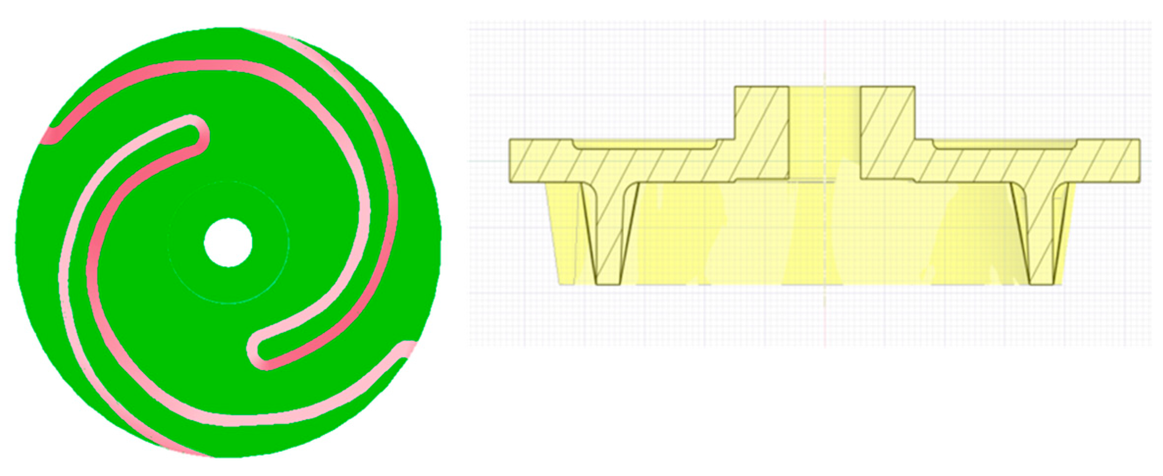
Moreover, the efficiency increased to 5.56% at 0.17 m3/min, and the average efficiency increased to 6.27%. It is understood that changing the shape of the impeller and casing is the best solution to improve the pump's performance [42]. Figure 18 shows the cross-sectional view of the original and newly designed impeller. Therefore, impeller shape change model 1 was considered optimal for manufacture.

5. Conclusions

The influence on the hydraulic performance optimization in a submersible pump was performed. The results of the study on performance improvement are summarized as follows:
(a)
The test data verified the computed results to secure the pump's performance.
(b)
The study modified the casing and impeller shape to improve hydraulic performance and used a flow balance block to reduce the inner space of the pump.
(c)
Changing the impeller shape reduces the power and increased efficiency, which can prevent flow disturbance. The attachment of the flow balance block increased the efficiency in the flow area more significantly than the operating point.
(d)
The flow separation inside the pump significantly improved and increased pump performance by up to 5.56% at the design flow rate.
(e)
This research obtained two Korean patents based on the performance improvement results above.
(f)
Further study should consider the performance test of the shape change model of the submersible pump.

6. Patents

Impeller for submersible pump (patent no.: 20-2021-0001433) and centrifugal submersible pump (patent no.: 10-2021-0058374). http://engpat.kipris.or.kr/engpat/searchLogina.do?next=MainSearch.

Author Contributions

M.R. conceived and designed the study, analyzed the results, wrote the paper, and edited the draft; S.-H.S. contributed to project administration, conceptualization and supervised the work; H.W.R. managed resources, experiment, and edited the draft; K.H.S. contributed to fund acquisitions and resources the work; K.C.S. contributed in experiment; and L.Z. advised on project work. All authors have read and agreed to the published version of the manuscript.

Funding

This research was funded by the Daeyoung Power Pump Co., Ltd., for the promotion of science.

Data Availability Statement

The study did not report any data.

Acknowledgments

This research was supported by Daeyoung Power Pump.

Conflicts of Interest

The authors declare no conflict of interest.

References

  1. Dabade, S.P.; Gajendragadkar, J. Design, Modelling and CFD Analysis of Submersible Vertical Turbine Pump (Polder Pump). In Proceedings of the National conference on recent trends in mechanical engineering; WCE, Sangli, India, 2016.
  2. Daeyoung Power Pump Catalog (DWE-Submersible Pump), Daeyoung Power Pump Co., Ltd., Korea, Available on the Web At Available online: http://www.dypump.co.kr/eng/sub02/view.php?id=95&ca_id=50&page=.
  3. Takacs, G. Electrical Submersible Pumps Manual: Design, Operations and Maintenance; Gulf Professional Publishing: Burlington- Massachusetts, USA, 2009; ISBN 9781856175579. [Google Scholar]
  4. Suh, S.-H.; Rakibuzzaman; Kim, K.-W.; Kim, H.-H.; Yoon, I.S.; Cho, M.-T. A Study on Energy Saving Rate for Variable Speed Condition of Multistage Centrifugal Pump. J. Therm. Sci. 2015, 24. [CrossRef]
  5. Kaya, D.; Yagmur, E.A.; Yigit, K.S.; Kilic, F.C.; Eren, A.S.; Celik, C. Energy Efficiency in Pumps. Energy Convers. Manag. 2008, 49, 1662–1673. [Google Scholar] [CrossRef]
  6. Goto, A.; Nohmi, M.; Sakurai, T.; Sogawa, Y. Hydrodynamic Design System for Pumps Based on 3-D CAD, CFD, and Inverse Design Method. J. Fluids Eng. Trans. ASME 2002, 124, 329–335. [Google Scholar] [CrossRef]
  7. Parrondo-Gayo, J.L.; González-Pérez, J.; Fernández-Francos, J. The Effect of the Operating Point on the Pressure Fluctuations at the Blade Passage Frequency in the Volute of a Centrifugal Pump. J. Fluids Eng. Trans. ASME 2002, 124, 784–790. [Google Scholar] [CrossRef]
  8. Wei-dong, S.H.I.; Wei-gang, L.U.; Hong-liang, W. Research on the Theory and Design Methods of the New Type. 2009, 1–7.
  9. Zhu, J.; Zhang, J.; Zhu, H.; Zhang, H.Q. A Mechanistic Model to Predict Flow Pattern Transitions in Electrical Submersible Pump under Gassy Flow Condition. Soc. Pet. Eng. - SPE Artif. Lift Conf. Exhib. - Am. 2018 2018. [CrossRef]
  10. Manivannan, A. Computational Fluid Dynamics Analysis of a Mixed Flow Pump Impeller. Int. J. Eng. Sci. Technol. 2011, 2, 200–206. [Google Scholar] [CrossRef]
  11. Ragoth Singh, R.; Nataraj, M. Parametric Study and Optimization of Pump Impeller by Varying the Design Parameter Using Computational Fluid Dynamics. Int. Rev. Mech. Eng. 2012, 6, 1581–1585. [Google Scholar]
  12. Ajay, A.J.; Stephen, S.E.A.; Smart, D.S.R. Shape Optimization of Submersible Pump Impeller Design. Proc. Int. Conf. Recent Adv. Aerosp. Eng. ICRAAE 2017 2017, 8, 56–69. [Google Scholar] [CrossRef]
  13. Zangeneh, M.; Goto, A.; Takemura, T. Suppression of Secondary Flows in a Mixed-Flow Pump Impeller by Application of Three-Dimensional Inverse Design Method: Part 1-Design and Numerical Validation. ASME J. Turbomach. 1996, 118, 536–543. [Google Scholar] [CrossRef]
  14. Goto, A.; Takemura, T.; Zangeneh, M. Suppression of Secondary Flows in a Mixed-Flow Pump Impeller by Application of 3d Inverse Design Method: Part 2-Experimental Validation. Proc. ASME Turbo Expo 1994, 1, 536–543. [Google Scholar] [CrossRef]
  15. Kim, S.; Lee, K.Y.; Kim, J.H.; Choi, Y.S. A Numerical Study on the Improvement of Suction Performance and Hydraulic Efficiency for a Mixed-Flow Pump Impeller. Math. Probl. Eng. 2014, 2014. [Google Scholar] [CrossRef]
  16. Kim, S.; Kim, Y.I.; Kim, J.H.; Choi, Y.S. Design Optimization for Mixed-Flow Pump Impeller by Improved Suction Performance and Efficiency with Variables of Specific Speeds. J. Mech. Sci. Technol. 2020, 34, 2377–2389. [Google Scholar] [CrossRef]
  17. Yan, P.; Chu, N.; Wu, D.; Cao, L.; Yang, S.; Wu, P. Computational Fluid Dynamics- Based Pump Redesign to Improve Efficiency and Decrease Unsteady Radial Forces. J. Fluids Eng. Trans. ASME 2017, 139. [Google Scholar] [CrossRef]
  18. Baun, D.O.; Flack, R.D. Effects of Volute Design and Number of Impeller Blades on Lateral Impeller Forces and Hydraulic Performance. Int. J. Rotating Mach. 2003, 9, 145–152. [Google Scholar] [CrossRef]
  19. Wu, D.; Yan, P.; Chen, X.; Wu, P.; Yang, S. Effect of Trailing-Edge Modification of a Mixed-Flow Pump. J. Fluids Eng. Trans. ASME 2015, 137. [Google Scholar] [CrossRef]
  20. Qian, C.; Luo, X.; Yang, C.; Wang, B. Multistage Pump Axial Force Control and Hydraulic Performance Optimization Based on Response Surface Methodology. J. Brazilian Soc. Mech. Sci. Eng. 2021, 43, 1–14. [Google Scholar] [CrossRef]
  21. Liu, Z.M.; Gao, X.G.; Pan, Y.; Jiang, B. Multi-Objective Parameter Optimization of Submersible Well Pumps Based on RBF Neural Network and Particle Swarm Optimization. Appl. Sci. 2023, 13. [Google Scholar] [CrossRef]
  22. Bai, L.; Yang, Y.; Zhou, L.; Li, Y.; Xiao, Y.; Shi, W. Optimal Design and Performance Improvement of an Electric Submersible Pump Impeller Based on Taguchi Approach. Energy 2022, 252, 124032. [Google Scholar] [CrossRef]
  23. Chen, J.; Wang, M.; Bao, Y.; Chen, X.; Xia, H. Mixed-Flow Pump Performance Improvement Based on Circulation Method. Front. Energy Res. 2023, 11, 1–12. [Google Scholar] [CrossRef]
  24. Suh, J.W.; Yang, H.M.; Kim, Y.I.; Lee, K.Y.; Kim, J.H.; Joo, W.G.; Choi, Y.S. Multi-Objective Optimization of a High Efficiency and Suction Performance for Mixed-Flow Pump Impeller. Eng. Appl. Comput. Fluid Mech. 2019, 13, 744–762. [Google Scholar] [CrossRef]
  25. Jeon, S.Y.; Kim, C.K.; Lee, S.M.; Yoon, J.Y.; Jang, C.M. Performance Enhancement of a Pump Impeller Using Optimal Design Method. J. Therm. Sci. 2017, 26, 119–124. [Google Scholar] [CrossRef]
  26. Siddique, H.; Mrinal, K.R.; Samad, A. Optimization of a Centrifugal Pump Impeller by Controlling Blade Profile Parameters. In Proceedings of the ASME Turbo Expo 2016: Turbomachinery Technical Conference and Exposition; American Society of Mechanical Engineers: Seoul, South Korea, 2016; pp. 1–8.
  27. Shim, H.S.; Kim, K.Y.; Choi, Y.S. Three-Objective Optimization of a Centrifugal Pump to Reduce Flow Recirculation and Cavitation. J. Fluids Eng. Trans. ASME 2018, 140. [Google Scholar] [CrossRef]
  28. Yang, Y.; Zhou, L.; Hang, J.; Du, D.; Shi, W.; He, Z. Energy Characteristics and Optimal Design of Diffuser Meridian in an Electrical Submersible Pump. Renew. Energy 2021, 167, 718–727. [Google Scholar] [CrossRef]
  29. Arocena, V.M.; Abuan, B.E.; Reyes, J.G.T.; Rodgers, P.L.; Danao, L.A.M. Numerical Investigation of the Performance of a Submersible Pump: Prediction of Recirculation, Vortex Formation, and Swirl Resulting from off-Design Operating Conditions. Energies 2021, 14. [Google Scholar] [CrossRef]
  30. Wei, Y.; Yang, Y.; Zhou, L.; Jiang, L.; Shi, W.; Huang, G. Influence of Impeller Gap Drainage Width on the Performance of Low Specific Speed Centrifugal Pump. J. Mar. Sci. Eng. 2021, 9, 1–17. [Google Scholar] [CrossRef]
  31. Han, C.; Liu, J.; Yang, Y.; Chen, X. Influence of Blade Exit Angle on the Performance and Internal Flow Pattern of a High-Speed Electric Submersible Pump. Water (Switzerland) 2023, 15. [Google Scholar] [CrossRef]
  32. Tong, Z.; Yuan, Y.; Zhang, C.; Zhang, Z.; Zhang, Y. Performance Analysis and Experimental Verification of Hydraulic Driven Axial Flow Pumps. J. Mech. Sci. Technol. 2023, 37, 2941–2947. [Google Scholar] [CrossRef]
  33. Fakher, S.; Khlaifat, A.; Nameer, H. Improving Electric Submersible Pumps Efficiency and Mean Time between Failure Using Permanent Magnet Motor. Upstream Oil Gas Technol. 2022, 9, 100074. [Google Scholar] [CrossRef]
  34. Zhu, J.; Zhu, H.; Zhang, J.; Zhang, H.Q. A Numerical Study on Flow Patterns inside an Electrical Submersible Pump (ESP) and Comparison with Visualization Experiments. J. Pet. Sci. Eng. 2019, 173, 339–350. [Google Scholar] [CrossRef]
  35. Rakibuzzaman, M.; Kim, K.; Kim, H.-H.; Suh, S.-H. Energy Saving Rates for a Multistage Centrifugal Pump with Variable Speed Drive. Open Access J. J. Power Technol. 2017, 97, 163–168. [Google Scholar]
  36. Ansys Inc. ANSYS-CFX (CFX Introduction, CFX Reference Guide, CFX Tutorials, CFX-Pre User’s Guide, CFX-Solver Manager User’s Guide, Theory Guide), Release 21.00R2, USA 2021.
  37. Georgiadis, N.J.; Yoder, D.A.; Engblom, W.A. Evaluation of Modified Two-Equation Turbulence Models for Jet Flow Predictions. AIAA J. 2006, 44, 3107–3114. [Google Scholar] [CrossRef]
  38. David C. Wilcox Turbulence Modeling for CFD; 1st ed.; DCW Industries, Inc.: La Cañada Flintridge, CA, USA, 1994.
  39. KS B 6301 Testing Methods for Centrifugal Pumps, Mixed Flow Pumps and Axial Flow Pumps, National Standard. Korean Standards Association, Korea; 2015.
  40. ISO 5198 Centrifugal, Mixed Flow and Axial Pumps-Code for Hydraulic Performance Tests-Precision Class. International Standard; 1987.
  41. Douglas, J.F.; Gasiorek, J.; Swaffield, J. Fluid Mechanics; 4th ed.; Prantise Hall: New Jersey, USA, 2001.
  42. Rakibuzzaman, M.; Suh, S.H.; Kim, H.H.; Ryu, Y.; Kim, K.Y. Development of a Hydropower Turbine Using Seawater from a Fish Farm. Processes 2021, 9, 1–24. [Google Scholar] [CrossRef]
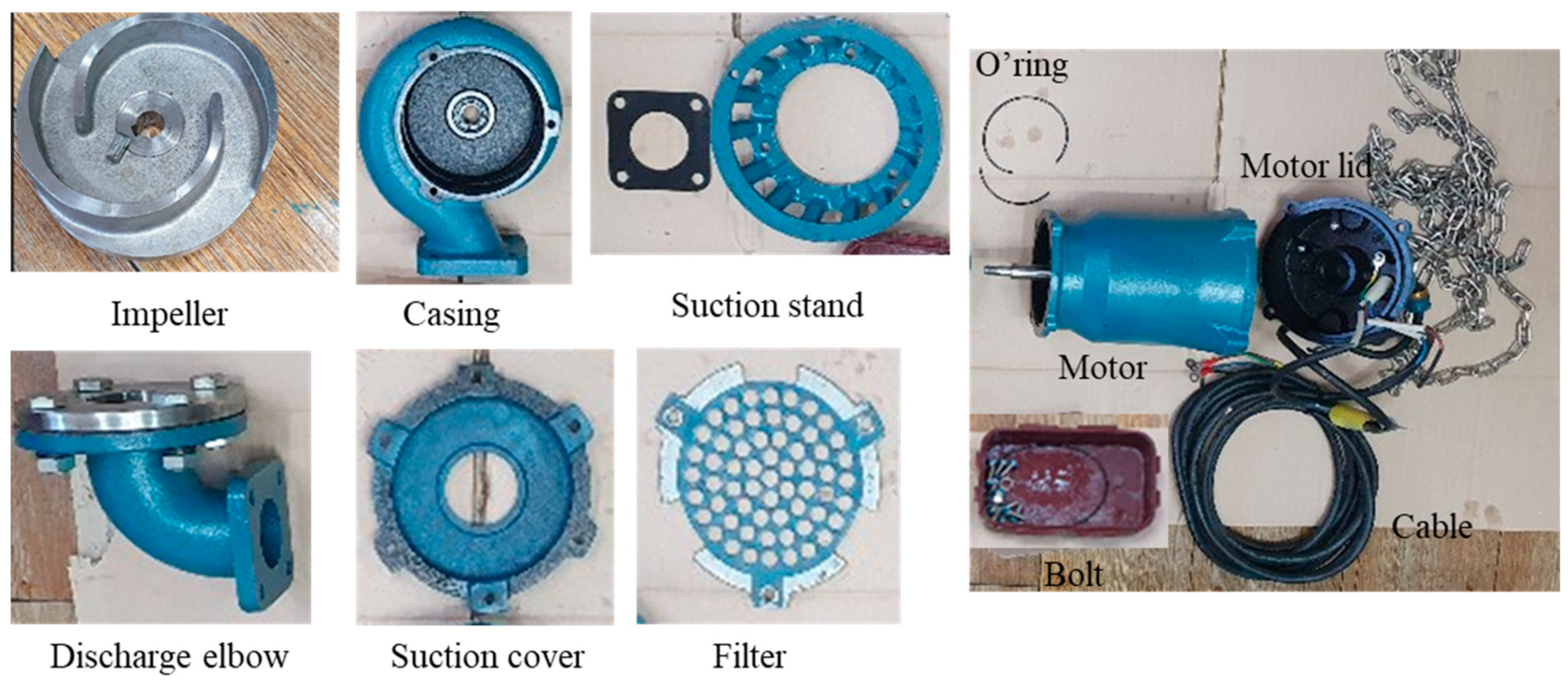
Figure 1. Disassemble of the submersible drainage pump (DWE-08).
Preprints 91152 g001
Figure 2. Assembly and disassembly drawing of the submersible drainage pump (DWE-08B) and its different views.
Preprints 91152 g002
Figure 3. Cross-sectional view of the pump’s key components.
Preprints 91152 g003
Figure 4. Hydraulic performance curve of various submersible pumps [2].
Preprints 91152 g004
Figure 5. Hydraulic performance optimization procedure of the submersible drainage pump.
Preprints 91152 g005
Figure 6. Submersible pump meshing grids for computation.
Preprints 91152 g006
Figure 7. Boundary conditions of the computational domain.
Preprints 91152 g007
Figure 8. Performance comparison between the experiment and computational of the submersible pump (a) Head vs. flow rate and (b) Efficiency vs. flow rate (Experimental uncertainty in N±3.298 rpm, Q±0.00178 m3/min, H±0.0989 m, and P±0.0102 kW).
Preprints 91152 g008
Figure 9. Velocity distributions analysis inside the casing (a) velocity vectors (b) velocity streamlines, (c) Blade-to-blade velocity streamlines.
Preprints 91152 g009
Figure 10. The position of the impeller inside the casing of the pump.
Preprints 91152 g010
Figure 11. Casing shape change model (a) original model (b) model 1 (c) model 2.
Preprints 91152 g011
Figure 12. Velocity streamlines comparison of shape change model (a) original model (b) model 1 (c) model 2.
Preprints 91152 g012
Figure 13. Performance comparison for casing shape change model (a) original model (b) model 1 (c) model 2.
Preprints 91152 g013
Figure 14. Flow balance block model.
Preprints 91152 g014
Figure 15. Impeller shape model 1.
Preprints 91152 g015
Figure 16. Pressure and velocity streamline distribution in different planes (a) original impeller, (b) impeller model 1.
Preprints 91152 g016
Figure 17. Performance comparison of impeller shape change model.
Preprints 91152 g017
Figure 18. Cross-sectional view of the optimum model (a) impeller model 1 (b) manufactured model.
Preprints 91152 g018
Table 2. Submersible pump performance data [2].
Model Outlet height (mm) Power (H.P.) Flow rate (m3/min) Head (m)
DWE-08B 50 1 0.16 10
Table 4. Comparison of pump efficiency according to casing shape changed model.
Flow rate
(m3/min)
Original (%) Model 1 (%) Model 2 (%) Efficiency improvement (%)
Model 1 Model 2
0.10 34.593 40.542 38.904 5.949 4.311
0.14 40.420 48.358 45.474 7.938 5.054
0.16 45.415 50.687 49.230 5.272 3.815
0.17 46.375 51.513 49.301 5.138 2.926
0.20 46.921 52.826 52.357 5.905 5.436
0.22 46.562 53.487 52.221 6.925 5.659
Disclaimer/Publisher’s Note: The statements, opinions and data contained in all publications are solely those of the individual author(s) and contributor(s) and not of MDPI and/or the editor(s). MDPI and/or the editor(s) disclaim responsibility for any injury to people or property resulting from any ideas, methods, instructions or products referred to in the content.
Copyright: This open access article is published under a Creative Commons CC BY 4.0 license, which permit the free download, distribution, and reuse, provided that the author and preprint are cited in any reuse.
Prerpints.org logo

Preprints.org is a free preprint server supported by MDPI in Basel, Switzerland.

Subscribe

© 2024 MDPI (Basel, Switzerland) unless otherwise stated