1. Introduction
In engineering practice, important tasks often arise for bodies whose transverse dimensions are significantly smaller than longitudinal ones (rods, plates, etc.). Wave motion in such objects drastically depends on the dynamic contact interaction of these bodies with the environment. Such tasks include, for example, the calculation of pile driving, the interaction of an underground pipeline with the ground, various friction devices – for example, clutch discs in cars. The determining role in such devices is played by the friction force that occurs on the contact surfaces both during wave motion and at its completion. The pattern of propagation and attenuation of elastic waves significantly depends on the magnitude of the friction force that attracts the close attention of researchers. For example, dynamics of elastic rods considering the dry friction law interaction with surrounding media is studied in [
1]. The monograph [
2] provides a detailed review of papers published before 1997 and devoted to interaction of an elastic rod and a rigid medium with a constant dry friction force acting on the contact surface in the presence of relative motion. The mentioned monograph presents exact analytical solutions to the problems of statics and dynamics of elastic and elastoplastic bodies with dry friction, as well as modeling of impact on a pipeline located in an elastic medium. A non-linear mathematical model of dynamic processes that appear under the stuck drill string release, using pulse installations with considering the internal and external friction, is developed in [
3]. Authors of [
3] found that the dry friction arising on the interaction surfaces of the drill string and the drill mud has a significant influence on the longitudinal wave propagation in the drill string. Elastic wave propagation in a cylindrical body in the presence of Coulomb friction on the contact surface with other nondeformable body and induced by the propagating wave parameters is considered in [
4]. It is shown that the accumulation of elastic energy in sliding plates on both sides of the fault can cause fluctuations in the sliding velocity even with constant friction [
5]. The authors of [
6] study the problem of longitudinal waves propagation in an elastic rod attached to a locally damaged foundation through a thin elastic layer. In [
7] an exact solution to the problem of the wave motion of a semi-infinite rod interacting with surrounding elastic medium according to the dry friction law under the action of an exponentially dropping dynamic load on butt of the rod and under a finite mass impact by a rigid body is obtained. It should be noted that there are no articles where dynamic problems for plates on a rough base are considered in the literature known to us.
In this paper, an exact analytical solution is given in quadratures to the boundary value problem of the propagation of elastic shear waves in a thin plate pressed against a rough base by uniform pressure (to obtain a constant value of the limiting friction force), with instantaneously applied and then constant tangential forces at the boundary of a round orifice. The radius and the moment of time of complete exhaustion of the elastic wave front are determined. For various values of the parameters of the problem, the trailing fronts of the elastic wave are found, after the passage of these fronts, a state of statical equilibrium occurs between the elastic and dry friction forces in the annular region of the plate adjacent to the orifice. Along the way, formulas for the originals of some Laplace transformants are obtained, which are not found in the known literature.
2. Setting of the Boundary Value Problem
Consider an infinite elastic homogeneous plate of constant thickness
h, with a circular cutout of radius
r0, lying on a hard, rough base and interacting with it according to Coulomb's dry friction law (
Figure 1). In the case when there is a slip between the plate and the base, a longitudinal friction force will act on an arbitrary part of the contact surface of area
S, the magnitude of which is equal in modulus
fNS, where
N – pressure on the plate,
f – the coefficient of friction between the materials of the plate and the base. In the absence of slippage, the friction force takes on some values, generally speaking, not the same at different points of the plate, but not exceeding the absolute value of the limit.
In the problem under consideration, as well as in [
1,
2,
3,
4,
5,
6], we will consider the longitudinal friction force to be constant. In the case when
h is small compared to the characteristic propagation length of the elastic pulse, the stress change over the thickness of the plate can be neglected and the friction force can be considered as volumetric one with density
.
Let's choose the beginning of the polar coordinate system in the center of the cutout (
Figure 1). Prior to the application of the load, we consider the plate to be at rest, unstressed and undeformed. Let at time
t = 0 tangential forces are applied instantly to the boundary of the orifice
r=
r0, the magnitude of which does not depend on the polar angle and is maintained constant in time. Then, due to the symmetry of the problem, the tangential stresses
τ(r,t) and the transversal velocity
v(r,t) satisfy the following system of partial differential equations:
Dimensionless variables and quantities are used here: the stress is related to the shear modulus μ of the plate material, the velocity is related to the velocity of transverse elastic waves (ρ – plate material density), the radial coordinate r is related to the radius of the hole r0, time t – by the time the shear wave travels a distance equal to the radius of the hole r0, and the parameter is introduced. The value of κ in the case of motion coincides with the sign of velocity, and in the case of rest takes some values from the interval (-1;1) depending on the radial coordinate of the section under consideration and is determined further from the solution of the problem.
We assume that in the presence of motion
v(r,t) > 0. Then in equations (1) it should be stated
, since in the problem under consideration, before of the elastic wave front
t=r-1, the friction force is zero (here
H(x) is the Heaviside function). In the accepted notations, the initial and boundary conditions acquire, respectively, the form:
where
τ0 – positive dimensionless constant.
3. Solution of the Boundary Value Problem
3.1. Laplace Transformation
The solution of the boundary value problem (1)-(3) is sought using the Laplace time transformation method. Applying the transformation to the equations of system (1) and boundary condition (3), and also taking into account (2), we obtain a system of two ordinary differential equations with respect to images of stress T(r,p) and velocity V(r,p):
where
and p is the transformation parameter.
The boundary condition (3) in the images takes the form:
3.2. Getting a Solution in Images
From (4) it is easy to obtain second-order ordinary differential equations for transformants
T(
r,p) and
V(
r,p)
:
Let's introduce a new variable y instead of r by the formula: y=pr. In this case, equations (7) and (8) will be rewritten as:
The homogeneous equations corresponding to (9), (10) are Bessel differential equations and their general solutions vanishing at infinities,
, are represented [
8] as:
where K
n(y) – MacDonald function of order n.
Partial solutions of equations (9) and (10) have the following form:
Returning to the variable r, taking into account (11) and (12), we write the general solution of equations (9) and (10), respectively, in the form:
To find the constants A and B in the relations (13), (14), we use the boundary condition (6) and the second of the equations (4). As a result, we obtain the following expressions for stress and velocity transformants:
For the transition from
and
to
and
in formulas (15) and (16), it is necessary to calculate the originals of the functions of a complex variable p:
which, apparently, are not found in the known literature. The originals of the additional terms in formulas (15), (16) have the form:
3.3. Inversion of Laplace's Images
To determine the originals of the images (17), we will perform contour integration. The MacDonald function K
n(z) (
) of the complex variable z is analytic on the entire complex plane with a cut along the negative part of the real axis [
8]. Consider the closed contour ACDEFA (
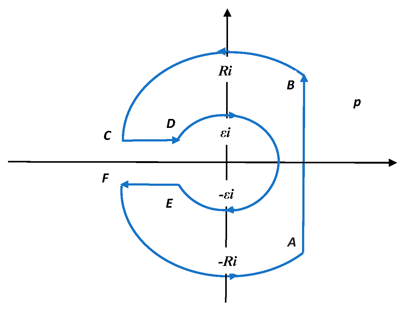
Figure 2), consisting of arcs BC and FA of a large circle of radius R centered at point p=0 of the complex plane p, as well as an arc DE of a small circle of radius ε centered at the same point, a segment AB of a vertical line p=γ+i∞ (here γ>0) and the shores of the CD and EF cuts. McDonald's function K
2(p) inside the specified contour, bypassed so that the area it bounds remains on the left, has only two complex-conjugate zeros [
8]:
The values of x
0 and y
0 with an accuracy of nine significant digits after the decimal point are equal [
9]:
We apply the residue theorem [
10] to functions
and
that are unambiguous and analytic inside a closed contour ABCDEF, with the exception of points
and
, in which both functions have simple poles. At the same time we have:
First, we transform the integral in (22), dividing it into integrals along smooth contour pieces. Since on the arcs BC and FA we have, respectively,
and
then, tending the radius R to infinity and taking into account the asymptotics K
n(z) under
[
8]:
by Jordan's lemma [
11] we will have under t>r-1:
In exactly the same way we get,
under t>r-1.
On the contour DE of a small circle we have p=εe
iφ, where φ decreases from π to -π. Tending the radius ε to zero and considering that
we have
Let us now consider integrals along the shores of the cut CD and EF. Noticing that,
and considering the relation
known in the theory of Bessel functions [
8], where
, and
is the Bessel function of an imaginary argument of order ν, we obtain a series of equalities:
Taking into account (28) and (29), we make the necessary calculations:
Now let's calculate the sum of residues in (21), (22). To do this, we need the following formulas linking the modified Bessel functions and their derivatives:
It is known that if z=z
0 is a simple zero of the function ψ(z) and φ(z
0)≠0, then we have [
10]:
. Therefore, given (32) when ν=2 and
,
, we have:
Substituting calculated integrals (23), (24), (26), (27), (30), (31), and also the relations (33), (34) in formulas (21), (22) and taking into account that
we will get new operational relations:
, t>r-1.
4. Analysis of the Pattern of Shear Wave Propagation and Discussion
4.1. Determination of True Velocities and Stresses
Since the originals of functions (17) are determined by the relations (35) and (36), then the transition to the true voltages and velocities in (15) and (16) is not difficult. To shorten and make numerical calculations easier, we introduce new ratios by formulas:
Taking into account (37), (38), the formulas for the voltage σ and the velocity w in the region of motion t > r-1, where the velocity is positive, will be written as follows:
In this case, the system (1) written with respect to σ(r,t) and w(r,t) will take the following form:
The solutions presented by formulas (39) and (40) are valid only in that part of the phase plane (r,t), where w(r,t)>0.
4.2. Determination of the stopping front of circular sections of the plate
Suppose that a curve on which the velocity of a part of circular sections w(r,t) vanishes is found and its equation is
at the same time
Differentiating (43) by the variable r and denoting the acceleration at the leading wave front as
, we find that
Here, the superscript "+" means that partial derivatives are taken from the side of the domain
. From equations (41) and (42) it is easy to obtain the following relations:
Let 's introduce the notation
differentiating which by the variable r we have:
Substituting the relations (44)-(46) into (47) and expressing acceleration
from the resulting formula, we have
Now let's assume that a particle located at time
t on the line
has a positive velocity at the next moment of time. Then it should be
at
κ = +1. If this is not possible, then the second possible variant of motion with a negative velocity is analyzed, for which the inequality
must be fulfilled at
κ = -1. If this also leads to a contradiction with the formula (48), then consequently
, and a static equilibrium is established between the forces of elasticity and friction in the region
, described by the equation arising from (48):
Here
is the residual distribution of tangential stresses after passing the stop front
(see the designation (46)). The frictional forces at the moment of stopping abruptly acquire values less than the maximum dry friction force, depending on the coordinate
r and representing the
– part of its limiting value, so that the function
is determined from equation (49):
Equating the expression (40) for velocity to zero, we obtain an implicit equation for determining the parametric family of zero velocity curves (by parameter
α), i. e. the stopping (trailing) front of an elastic wave:
The zero velocity curves are thus the level lines of the function on the right side of equation (51).
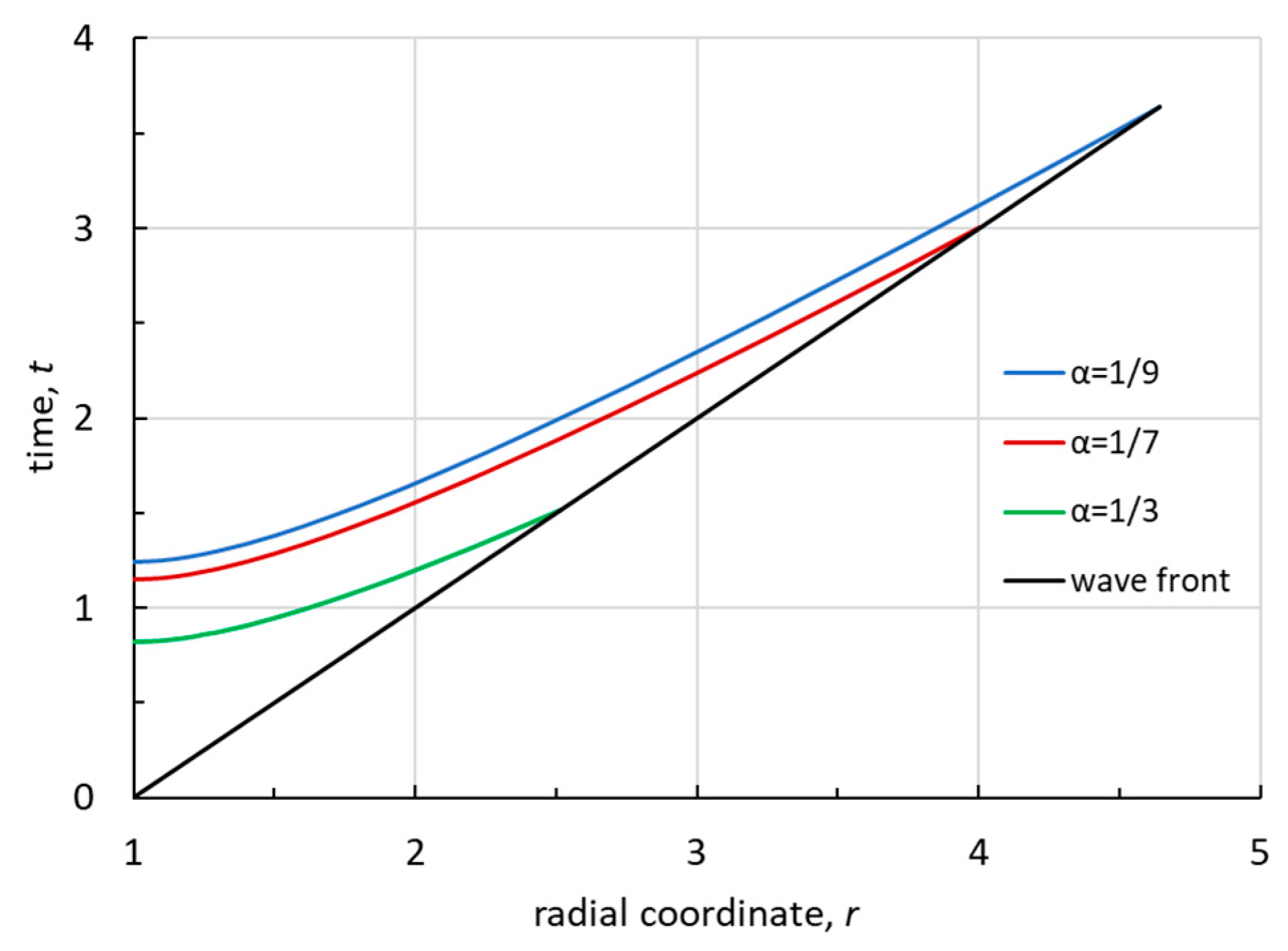
Figure 3 shows curves
for the values of the parameter α equal
, determined numerically based on equation (51) using the Mathematica® application software package. As expected, the stopping fronts
of the plate sections at lower
α (lower friction force) are located on the phase plane (
r,
t) above.
4.3. Determination of Residual Stresses after Passing the Stop Front
Differentiating expressions (39) and (40) by time
t gives:
Further, since
, and
(see Eq. (52)), then
for any values of
α. Consequently, the initial velocity of propagation of the stopping front
is infinite. The analysis of the possibilities of motion in the region, carried out on the basis of the relation (48), shows that
is the trailing front of an elastic wave, so that after its passage a static equilibrium between elastic forces and friction forces is established on the plate section
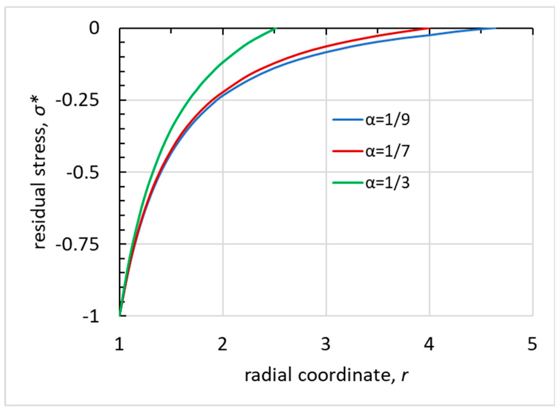
, described by equation (49). The distribution of residual stresses
after passing the stopping front is shown in
Figure 4 for three values of
α.
It can be seen from
Figure 4 that the larger the parameter α, the faster and on a shorter section the residual tangential stresses
decrease modulo from 1 to zero. In the cross section
, at the moment of time
, a strong discontinuity degenerates at the leading front of the elastic wave
t=
r-1, so that
and, therefore,
is the maximum distance to which transverse elastic waves propagate in the plate. The value of
, as a function of the parameter
α, is easy to determine by integrating the relations between the complete differentials of partial derivatives of the transversal displacement
u(
r,
t) (
) of the circular sections of the plate along the leading front
t=
r-1. It can be shown, using system (1), that
u(
r,
t) satisfies the following hyperbolic differential equation:
The characteristics of equation (55) are straight lines
and along them the characteristic conditions have the form:
where indicated
. Since on the leading front t=r-1 the following relations are valid
then, substituting them in (56), we obtain an ordinary differential equation for determining the velocity
v on this front:
. The solution of the last equation is
. Using the relations (57) and Hooke's law
, as well as the boundary condition (3), we find the velocity and stresses at the leading front:
Formulas (58) with respect to the variables
w and
σ will be rewritten in the following form:
From conditions (54) we find a point on the phase plane where the shear wave is completely exhausted:
4.4. Determination of Residual Stresses in the Case of Quasi-static Loading
In the case of limiting equilibrium, when
κ=+1, with quasi-static loading of the plate with the same load as in case of dynamic loading, the stress
σstatic satisfies the equilibrium equation:
and the condition at the boundary of the hole
r=1:
The solution of the Cauchy problem (61), (62) is easily constructed and the expression for
σstatic has the form:
From (63) we find the boundary of the slip region in the case of realization of the limiting equilibrium:
In the general case, when 0<
κ<1, the length of the slip area is obviously greater than in the limiting case (64):
Comparing (60) and (64), we conclude that under dynamic loading, the length of the slip region (the region of motion) is significantly longer than under quasi-static (in the case of limiting equilibrium). In other words, there is a quadratic relationship between them: .
It should be noted that the essential difference between the problem considered here and a similar problem for a semi-infinite rod (pipeline) immersed in an elastic Winkler medium with a friction force on its lateral surface depending on local deformation [
7] is that during quasi-static loading of the rod, slippage between its lateral surface and the environment occurs throughout the length of the rod. Here, for all possible states of static equilibrium, the area of slippage in the presence of friction is always finite (see (65)).
4.5. Distribution of Friction Forces after Passing the Stopping Front
The nonlinear distribution of friction forces in the region
after passing the stopping front
becomes immediately known as soon as the function
is determined by formula (50). Calculations show that
does not always monotonically decrease from its maximum value at the boundary of the hole
r = 1 to the minimum in cross sections
. From the formula (50) and the equations of motion (41), one can obtain the expression:
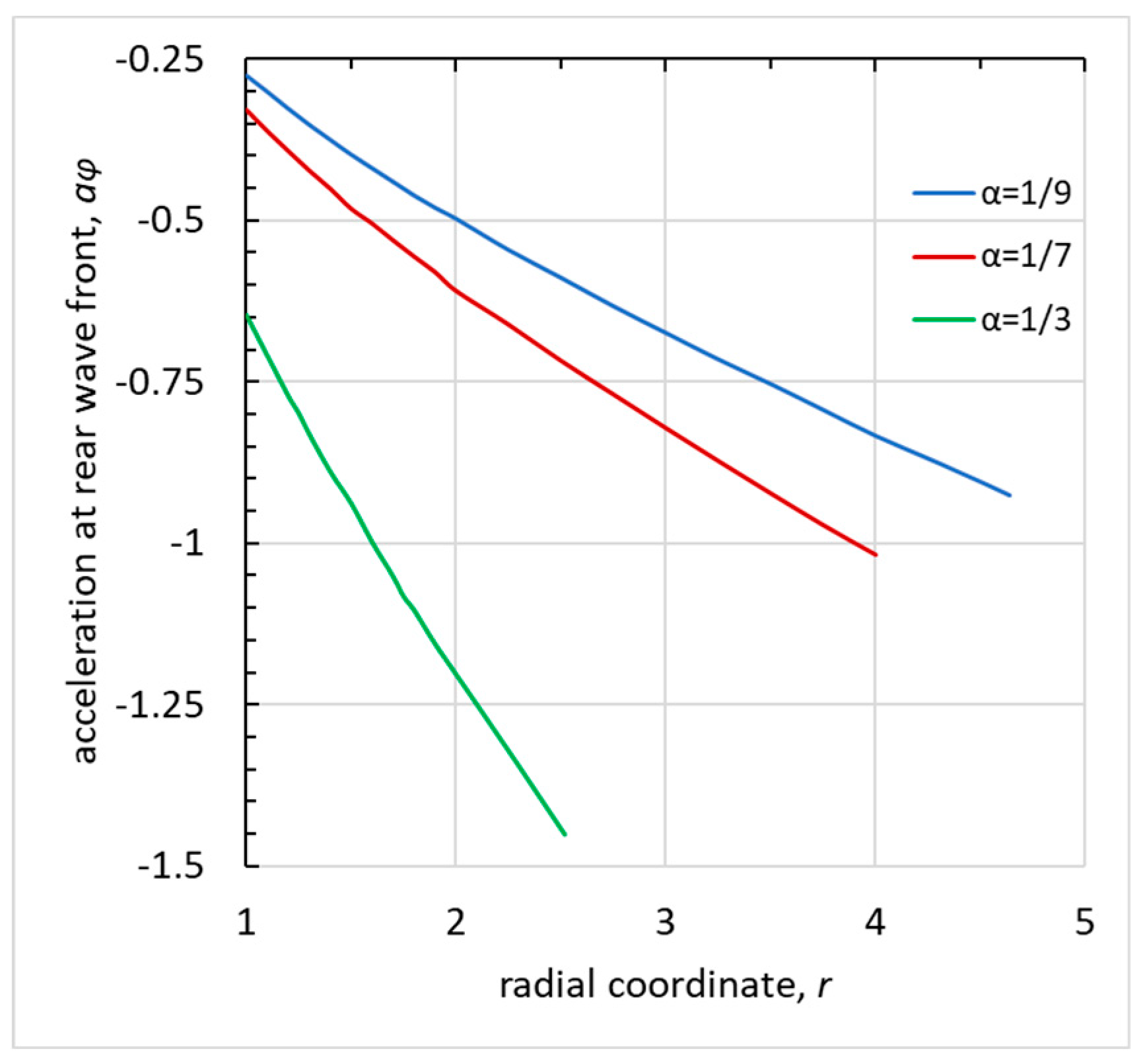
Acceleration graphs
at the stopping front
of the sections, determined numerically using the Mathematica® application software package, are shown in
Figure 5 for the values of the parameter
α equal to
. From formula (66), considering that
, it is possible to obtain maximum and minimum values of
depending on the parameter α:
Table 1 shows the values
– the moment when the hole boundary stops;
for various
α.
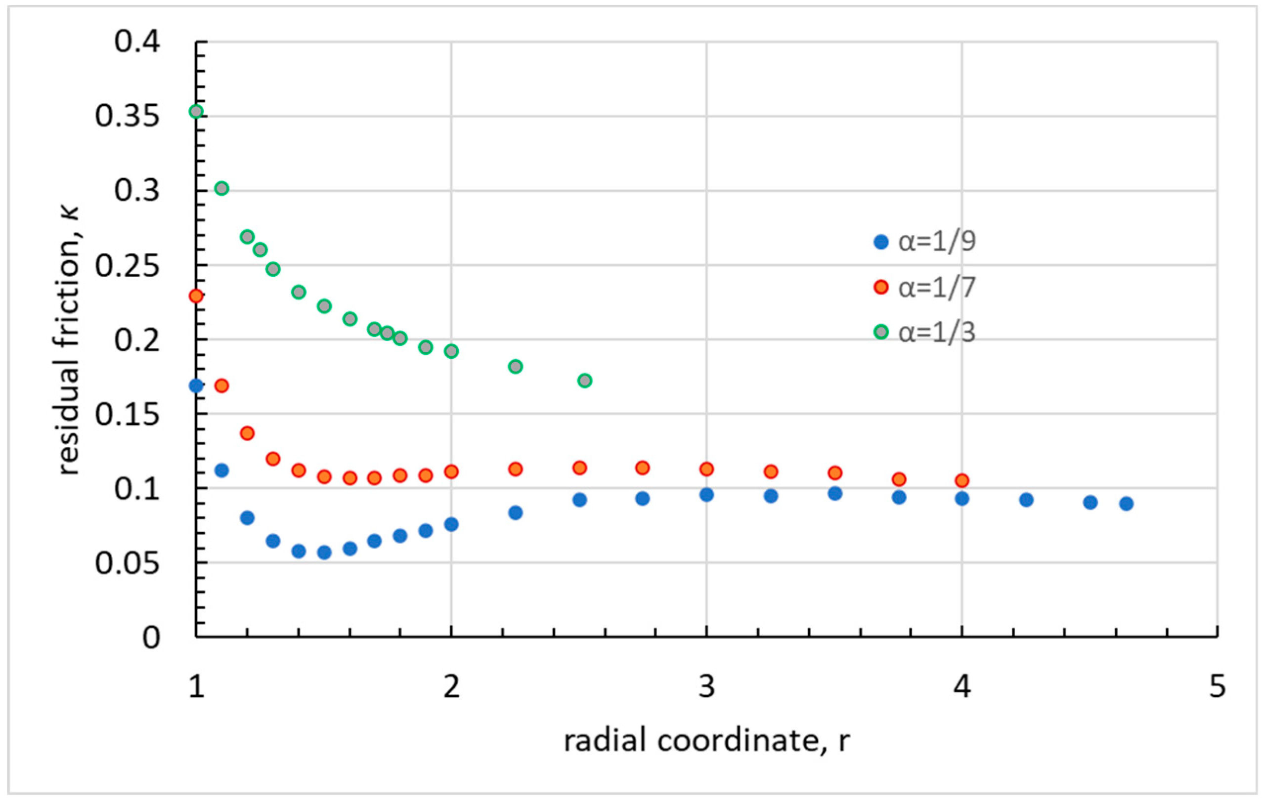
Figure 6 shows the dependences of the residual friction force
κ(
r) in various sections after passing the stopping front, depending on the magnitude of the limiting friction force
α. It can be seen that the residual friction force does not always decrease monotonically from its value at the boundary of the hole to the value on the elastic wave depletion section. The greatest drop in
κ(
r) is observed near the boundary of the hole. At small relative values of the friction force (
α = 1/9), noticeable fluctuations of the residual friction force are observed in the region of the plate through which the elastic shear wave passed.
5. Discussion
The results obtained in this study additionally allow us to establish new mathematical relations, as well as the solution of an important boundary problem about a tangential impact on the surface of a cylindrical cavity in an elastic space.
Assuming
t=
r-1 in formulas (39) and (40) and comparing the obtained relations with the expressions for
σ and
w (59) on the leading front of the elastic shear wave, we have new identities valid for
:
which are not found, apparently, in the well-known literature. Substitute
r=1 into the formula (68), then considering the identity
known in the theory of Bessel functions [
8], it will be written in the following form (see (19)):
Checking the resulting integral with the help of the NIntegrate utility of the Mathematica® computing shell naturally gives the same result.
If we put
α=0 in expressions (39) and (40), then as a result we will have a solution to the axisymmetric problem of the propagation of shear waves in an infinite isotropic space with a cylindrical cavity
r =1, when the tangent forces
σ(1,
t)=-
H(
t) are set on its boundary (plane problem):
From formula (70) it is easy to obtain the law of change of the transversal velocity in time at the boundary of the cylindrical cavity:
so at the moment of time t=0, the boundary abruptly acquires velocity
. When
both terms in the last formula tend to zero, that is, the shear wave exponentially decays in time.
In conclusion, we note that formulas (6) indicate a method for determining the magnitude of the limiting friction force. Indeed, by measuring the velocity jump w1 in any circular section r=r1 of the plate at the time of the passage of the leading front t=r-1, we easily find the value of α by the formulas (59), , and consequently the depletion coordinate (see (60)) of the leading front of the shear wave.
6. Conclusion
An exact analytical solution of the problem of the propagation of elastic shear waves in a plate interacting with a rigid rough base according to Coulomb's dry friction law in the case of a tangential impact on the surface of a circular hole is obtained. Depending on the ratio of the specific friction force to the load amplitude, the finite areas of motion in the plate and the radius of complete exhaustion of the wave front are determined. In the future, it is proposed to consider similar boundary value problems with a different type of load at the boundary of the hole in the plate.
Funding
This research received no external funding.
Institutional Review Board Statement
Not applicable.
Data Availability Statement
Data sharing not applicable.
Conflicts of Interest
The author declares no conflict of interest.
References
- Mogilevsky, R.I. , Ormonbekov, T.O., Nikitin, L.V. Dynamics of Rods with Interfacial Dry Friction. Journal of the Mechanical Behavior of Materials, 1993, 5, 85–93. [Google Scholar] [CrossRef]
- Nikitin, L.V. Statics and Dynamics of Solids with External Dry Friction. Moskovskyi Litsei: Moscow, Russia, 1998 (in Russian).
- Kharchenko, Y. , Hutyi, A., Haiduk, V. The Influence of Friction Forces on Longitudinal Wave Propagation in a Stuck Drill String in a Borehole. Tribologia 2018, 6, 79–87. [Google Scholar] [CrossRef]
- Sultanov, K.S. , Khusanov, B.E., Rikhsieva, B.B. Elastic wave propagation in a cylinder with external active friction. J. Phys.: Conf. Ser. 2021, 1901, 012125. [Google Scholar]
- Karachevtseva, I. , Dyskin, A.V., Pasternak, E. Generation and propagation of stick-slip waves over a fault with rate-independent friction. Nonlin. Processes Geophys. 2017, 24, 343–349. [Google Scholar] [CrossRef]
- Shatskyi, I. , Perepichka, V., Vaskovskyi, M. Longitudinal waves in an Elastic Rod Caused by Sudden Damage to the Foundation. Theor. Appl. Mech. 2021, 48, 29–37. [Google Scholar] [CrossRef]
- Filippov, A.N. Dynamic Impact on a Pipeline Considering Dry Friction on its Surface. Mechanics of Solids 2019, 54, 1144–1150. [Google Scholar] [CrossRef]
- Watson, G.N. A Treatise on the Theory of Bessel Functions, 2nd ed.; The Macmillan Company: New York, USA, 1944. [Google Scholar]
- Kerimov, M.K. , Skorokhodov, S.L. Calculation of the Complex Zeros of the Modified Bessel Function of the Second Kind and its Derivatives. U.S.S.R. Comput. Math. Math. Phys. 1984, 24, 115–123. [Google Scholar] [CrossRef]
- Markushevich, A.M. The Theory of Analytic Functions: A Short Course, MIR Publishers: Moscow, Russia, 1983.
- Ditkin, V.A., Prudnikov, A.P. Handbook of Operational Calculus, Vysshaya shkola: Moscow, Russia, 1965 (in Russian).
|
Disclaimer/Publisher’s Note: The statements, opinions and data contained in all publications are solely those of the individual author(s) and contributor(s) and not of MDPI and/or the editor(s). MDPI and/or the editor(s) disclaim responsibility for any injury to people or property resulting from any ideas, methods, instructions or products referred to in the content. |
© 2023 by the authors. Licensee MDPI, Basel, Switzerland. This article is an open access article distributed under the terms and conditions of the Creative Commons Attribution (CC BY) license (http://creativecommons.org/licenses/by/4.0/).

