Preprint
Article

Scattering of Ultrashort X-ray Pulses from Oriented NV Centers in the Diamond Structure

Altmetrics

Downloads

126

Views

54

Comments

0

A peer-reviewed article of this preprint also exists.

Submitted:

23 November 2023

Posted:

24 November 2023

You are already at the latest version

Alerts
Abstract
It is well known that the basis of diffraction analysis of matter is scattering, including scattering of ultrashort laser pulses. In the theory of scattering of ultrashort pulses the pulse duration parameter is usually not taken into account, which leads to some error. This error may be more significant than the considered effects in the scattering of the pulse on the studied structure. In this paper it is shown that the pulse duration parameter should be taken into account when scattering X-ray pulses on oriented diamonds with NV-centers. It is shown that the scattering spectra can be used to judge the orientation of NV centers in the diamond structure. The obtained results may be very different from the widely used theory of diffraction analysis, which confirms the necessity of taking into account the pulse duration parameter in the diagnosis of complex structures.
Keywords: 
Subject: Physical Sciences  -   Radiation and Radiography

1. Introduction

X-ray diffraction analysis of matter (XRD) using ultrashort laser pulses (USP)is currently gaining great relevance [1,2,3]. First of all, this development of the physics of ultrashort pulses was facilitated by the emergence of new installations generating such pulses [4,5,6,7,8]. Such sources primarily include free electron lasers (XFELs)[9], which can generate very high peak and average powers of laser radiation in the X-ray frequency range. The generation of attosecond X-ray pulses by XFELs is currently being reported [10,11]. The possibility of creating zeptosecond pulses is reported [12]. Achieving a subfemtosecond barrier with high peak power makes it possible to study excitation in a molecular system, the movement of valence electrons with high temporal and spatial resolution, for example [13]. Indeed, with the help of such USPs it is possible to study the structure of a substance with high temporal and spatial resolution, since it is technically possible to carry out such studies. Despite this, there is a need for new theoretical approaches that take into account the specific interaction of such USPs with complex structures, including promising materials that can be used in quantum technologies.
One of the most interesting materials in quantum technologies is diamond with N V centers. An N V center (nitrogen vacancy center) in diamond is one of many point defects in diamond that appear when a carbon atom is removed from a lattice site and the resulting vacancy binds to a nitrogen atom. The uniqueness of the N V defect is due to the fact that the spins of individual central electrons can be easily manipulated by magnetic, light, electric and microwave fields, which makes it possible to write quantum information (qubits) onto the spin of the central nucleus. What is especially important is that such manipulations are possible even at room temperature [14,15]. Of particular importance for quantum technologies are the so-called N V centers (usually denoted as N V ), which have an additional electron located at the vacancy site and form a spin S = 1 pair with one of the vacancy electrons. This leads to improvements in technologies for creating and diagnosing materials based on synthetic diamond plates with N V centers (color centers), for example, [16]. Of great interest are defects in diamonds created from layers of N V centers. This is due to the fact that layers localized in a crystal make it possible to produce a quantum sensor for magnetometry of objects with high spatial resolution. The layers can also be used in diamond quantum electronics elements [17]. These layers can be created in several ways. First, nitrogen is implanted into a crystal grown by the high-pressure–high-temperature method (HPHT) during growth, then the crystal is irradiated with heavy charged particles (for example, protons) at a certain energy. Due to the Bragg peak and subsequent annealing, a thin layer of N V centers is formed [18]. Secondly, they use the chemical vapor deposition method (CVD) technology [19]. In this case, layers of nitrogen are formed during the growth of the wafer, and then the wafer is irradiated with electrons and annealed to create vacancies. To use such N V centers in quantum technologies, it is necessary to be able to determine not only their presence and quantity in the crystal structure, but also the orientation of these centers. Determining their orientation is quite difficult, although it is possible using the optically detected magnetic resonance (ODMR) method, since the N V center is sensitive to the external magnetic field [20]. Due to the symmetry of the crystal, there are 4 possible orientations of the N V axis in the diamond lattice: 111,111,111,111. Determining these directions is a non-trivial and quite complex task.
Currently, ultrashort laser pulses are increasingly being used in the diffraction analysis of matter. Such ultrashort pulses make it possible not only to determine the structure of matter, but also the dynamic processes that occur in them. Diffraction analysis of such structures with ultra-high spatial and temporal resolution is a promising direction in modern physics. Femto- and especially attosecond scattering processes on such structures with time resolution have been little studied and are currently being actively developed [5,7,8,21,22,23,24,25,26,27,28,29,30]. Typically, the scattering of X-rays by various periodic and complex structures is described as the scattering of plane monochromatic waves of infinite duration in time[3,31]. This means that the duration of such USP when scattering on such structures is not taken into account, which leads to inaccurate use of known approaches in XRD [3,5]. Such inaccuracies can have a large error, which will lead to incorrect “decoding” of the structure under study. Indeed, it was recently shown that the scattering of attosecond USPs on DNA structures can differ significantly from the previously known XRD theory [32,33]. Also, if you do not take into account the duration of USP, then you can incorrectly determine various mutations and defects in DNA [34]. Thus, the study of USP scattering on diamond with a given orientation of N V centers, taking into account the USP duration, is an urgent task. Indeed, the elemental composition of a diamond crystal with different orientations of N V centers is the same, which means that the scattering spectra from such N V centers differ by a small amount, and if the error of the calculation method is quite large, then the effect from the orientation of N V centers will not be noticeable. Thus, theory and calculations are needed, where the pulse duration will be an important parameter of the theory under consideration.
In this work, the scattering of USP on diamond with different orientations of N V centers is studied. It is shown that using USP it is possible to determine the orientation of N V centers in the crystal structure. It is also shown that pulse duration is an important parameter, especially when using attosecond pulses, and the use of previously known XRD theory can lead to large errors that are more significant than the differences in the scattering spectra of USPs at different orientations of N V centers.
Further we will use the atomic system of units: = 1; | e | = 1; m e = 1, where is the Dirac constant, e is the electron charge, m e is the electron mass.

2. USP Scattering on Oriented N V Centers

Let us consider the scattering of USPs incident in the direction n 0 onto oriented N V centers in the diamond structure. As an example, let us consider scattering on N V centers located in a plane for all 4 directions of their orientation. Let’s define orientation 1, presented in Figure 1; orientation 2 shown in Figure 2; orientation 3 presented in Figure 3; orientation 4 presented in Figure 4 .
In the works [24,26,27,32,33,35] it was shown that when using the sudden disturbance approximation, it is possible to obtain expressions for calculating scattering spectra taking into account the duration of the incident USP. The special role of the pulse duration during its scattering is determined by attosecond pulses, i.e., such pulses can give a large difference in the scattering spectra when using the previously known theory and the theory developed in these works. These are the pulses that will be used in this work. Further we will consider the pulse to be spatially inhomogeneous, i.e., Let us choose the electromagnetic field strength USP in the general form E ( r , t ) = E 0 h ( t n 0 r / c ) , where E 0 is the field amplitude, and h ( t n 0 r / c ) is an arbitrary function that determines the shape of the USP, c is the speed of light (in a.e. c 137 ). We will not consider USP fields to be so strong that nonlinear effects appear. These effects begin to appear when the USP magnetic field also needs to be taken into account. As was shown in the works [24,26,35], the USP magnetic field can be ignored at intensities I 10 25 W / cm 2 . In this case, as was shown in [32,33], scattering spectra (scattered USP energy per unit solid angle) can be represented as can be represented as
d ε d Ω k = E 0 n 2 ( 2 π ) 2 c 3 τ | f ˜ ( x ) | 2 d x [ i = 1 s N e , i N A , i ( 1 | F i ( p 0 ) | 2 ) + i , j = 1 s γ i , j ( p 0 , p τ ) N e , i N e , j F i ( p 0 ) F j * ( p 0 ) ] , γ i , j ( p 0 , p τ ) = A i , A j e i p 0 ( R A i R A j ) | f ˜ ( x ) | 2 e i x p τ ( R A i R A j ) d x | f ˜ ( x ) | 2 d x .
where p 0 = ω 0 c ( n n 0 ) has the meaning of a recoil impulse at the carrier frequency ω 0 during USP scattering, and p τ = 1 c τ ( n n 0 ) ; h = e i ( ω 0 t k 0 r ) f ( ( t n 0 r / c ) / τ ) , where the f function defines the USP profile, then we get f ˜ ( ( ω ω 0 ) τ ) = e i ( ω ω 0 ) τ η f ( η ) d η is the Fourier transform of the function f ( η ) ; N e , i is the number of electrons in the atom i variety; N A , i is the number of atoms i variety; F i ( p 0 ) = 1 N e , i ρ e , i ( r ) e i p 0 r d 3 r is the form factor of the i atom of the variety with electron density ρ e , i ( r ) . The parameter s is the number of different kinds of atoms in the system. In our case, s can be considered equal to 2, since we are considering two independent atoms: carbon (C) and nitrogen (N). It should be taken into account that the place where there is a vacancy is empty, i.e., there are no atoms there.
Next we will use the model of independent atoms. In this model, the entire crystal or molecule consists of individual neutral, non-interacting atoms. Indeed, such a model can be applied due to the fact that the bulk of the electrons on which USP is scattered are not valence electrons and there are significantly more of them than electrons involved in interatomic bonds. Thus, we will further use the well-known model of electron density distribution in atoms [36]. The electron density of such atoms ρ e , i ( r ) = N e , i 4 π r k = 1 3 A k , i α k , i 2 e α k , i r , where A k , i , α k , i are constant coefficients (for all varieties of atoms with number i ) defined in [36]. The result is a simple expression for F i ( p 0 ) = k = 1 3 A k , i α k , i 2 p 0 2 + α k , i 2 .
Let us choose the form of the falling USP in the form of a Gaussian form h ( t ) = e i ( ω 0 t k 0 r ) e α 2 ( t n 0 r / c ) 2 , where α = 1 / τ ( τ is the pulse duration), k 0 = n 0 ω 0 / c . Let us add that the shape of the pulse can be chosen arbitrarily depending on the task at hand. In the case of X-ray pulses, multi-cycle pulses are usually used, i.e., where the number of fluctuations included in the USP is large. Mathematically, the multi-cycle pulse condition can be represented as ω 0 τ 1 . We choose a Gaussian pulse since this type of pulse is the most common. For example, in [37] an exact description of the subcyclic pulse beam (SCPB) was found, where in the case considered in this article ( ω 0 τ 1 ) the solution has the form of a Gaussian pulse. In the multi-cycle pulse case we obtain f ˜ ( ( ω ω 0 ) τ ) = π e ( ω ω 0 ) 2 / 4 α 2 , then using Eq. (1) it will turn out
d ε d Ω k = E 0 n 2 2 c 3 α 2 π i = 1 s N e , i N A , i ( 1 | F i ( p 0 ) | 2 ) + i , j = 1 s γ i , j ( p 0 , p τ ) N e , i N e , j F i ( p 0 ) F j * ( p 0 ) , γ i , j ( p 0 , p τ ) = A i , A j e i p 0 ( R A i R A j ) ) e 1 2 ( p τ ( R A i R A j ) ) 2 .
Indeed, this expression contains characteristics responsible for the duration of the ultrashort pulse τ , which means that Eq.(2)) is more general in the theory of X-ray scattering than the well-known and widely used expression in scattering theory. If this duration parameter is made large, i.e., τ , and take into account only the coherent term in scattering, then we obtain from Eq.(2)) the well-known expression for the scattering of long (monochromatic) X-rays [33]. The main difference between Eq. (2) and the previously known theory is determined by the factor γ i , j ( p 0 , p τ ) , the analysis of which determines the difference between our theory and the previously famous. As was shown in early works [27,32,33] the difference between the theory presented here and the previously known one is mainly observed when using attosecond and shorter pulses on certain types of structures. Analysis of the parameter γ i , j ( p 0 , p τ ) provides a qualitative explanation of the influence of the pulse duration on the scattering spectra. If the spatial dimensions of the pulse c τ are such that only part of the N V centers will fall into this size, then from this region of space there can be scattering by this group of N V centers. All carbon atoms and N V centers that do not fall into the region of c τ space are scattered independently of each other without diffraction. In the case of long-duration pulses, the space region is c τ , which means diffraction will be from all atoms and N V centers, i.e., from a very large area of space.
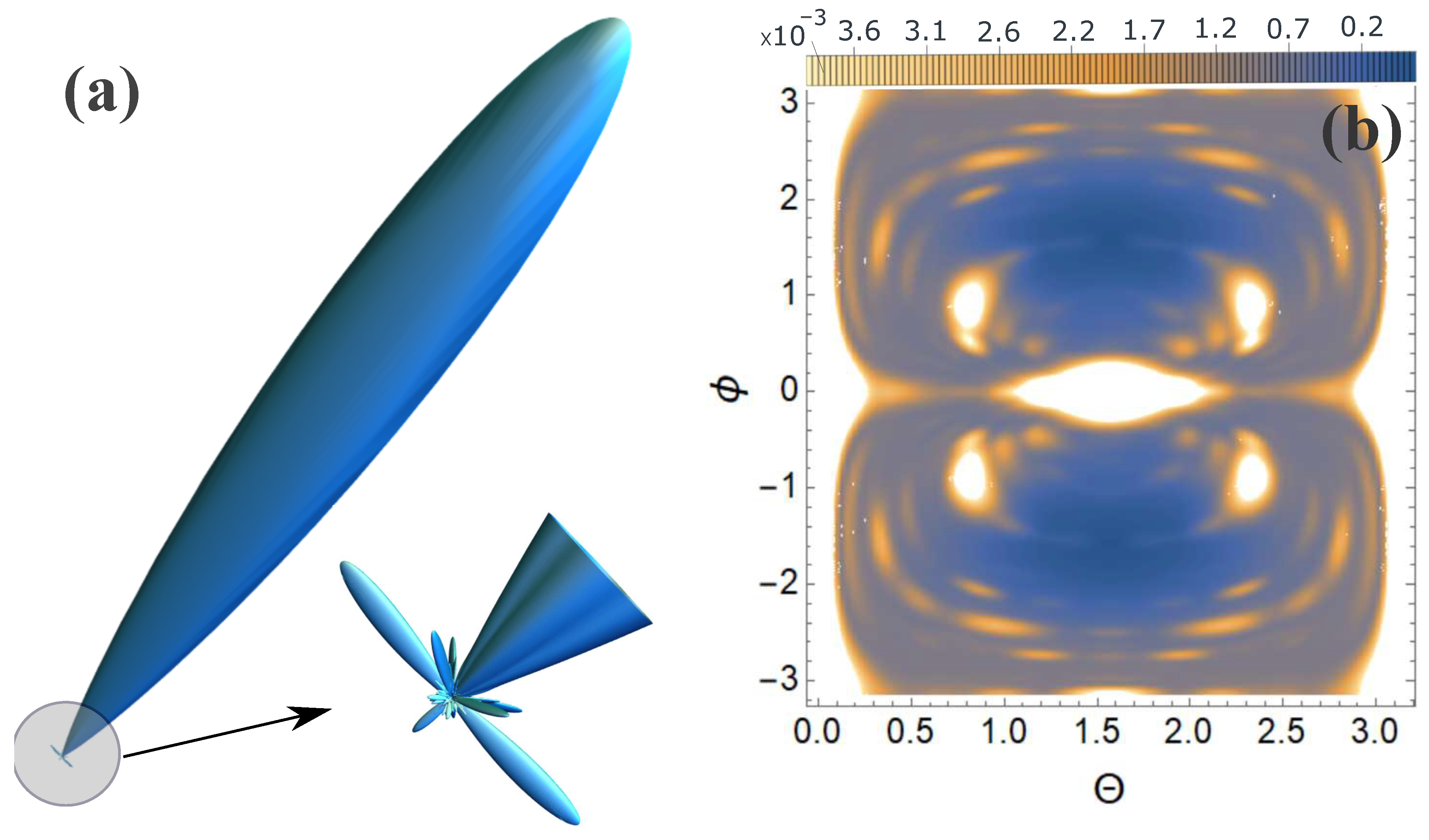
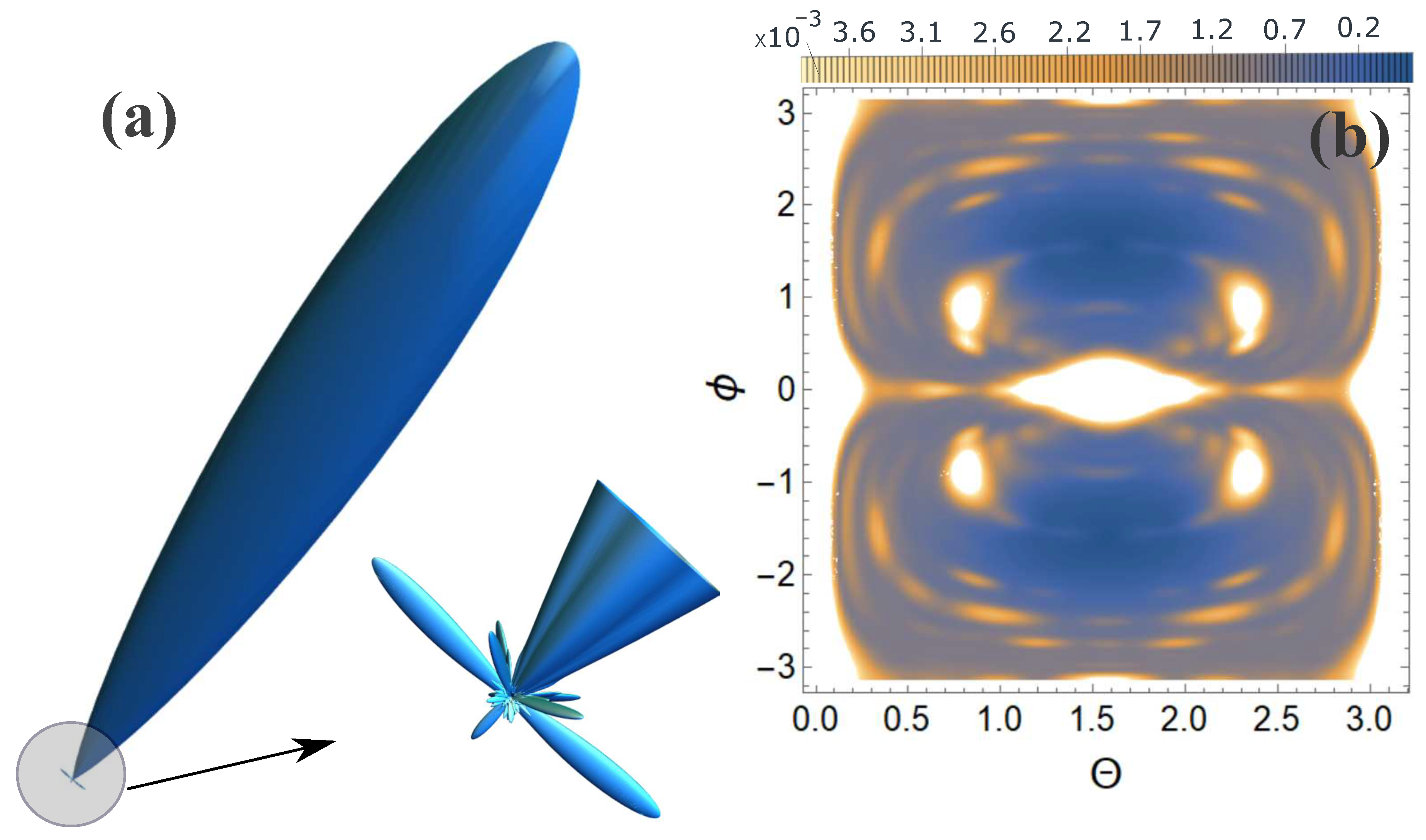
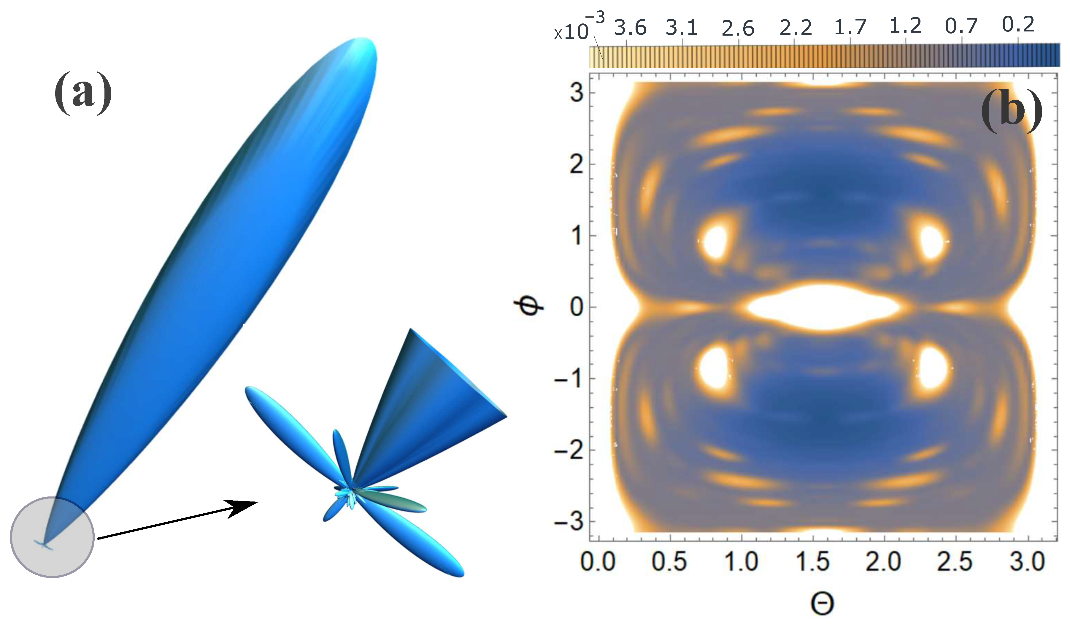
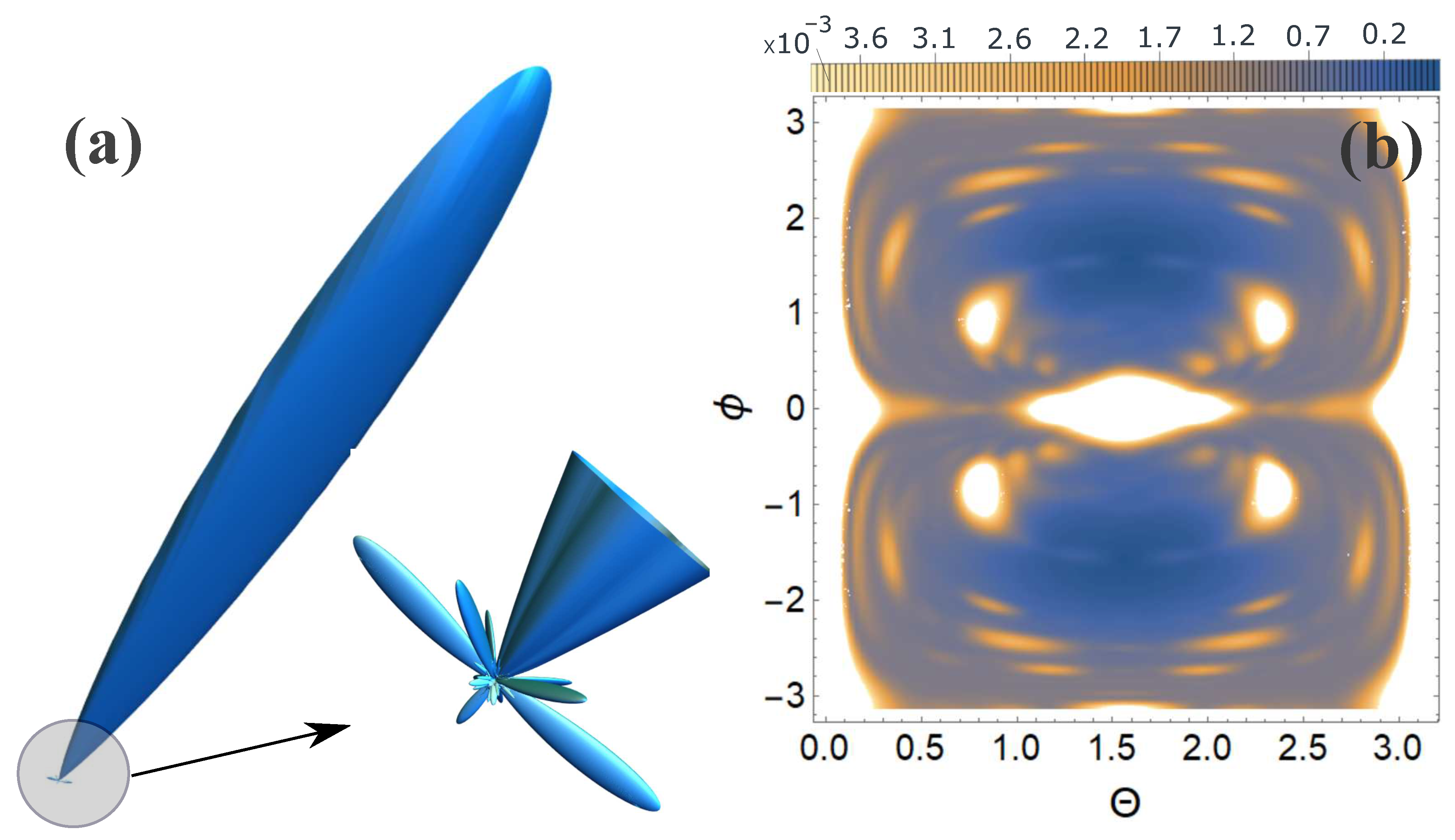
Next, we present calculations of USP scattering on the systems presented in Figure 1, Figure 2, Figure 3 and Figure 4. Calculation of scattering spectra using the formula (2) is shown in Figure 5, Figure 6, Figure 7 and Figure 8. The pulse falls as shown in Figure 1, Figure 2, Figure 3 and Figure 4 with photon energy ω 0 = 7.46 k e V , pulse duration τ = 10 as.
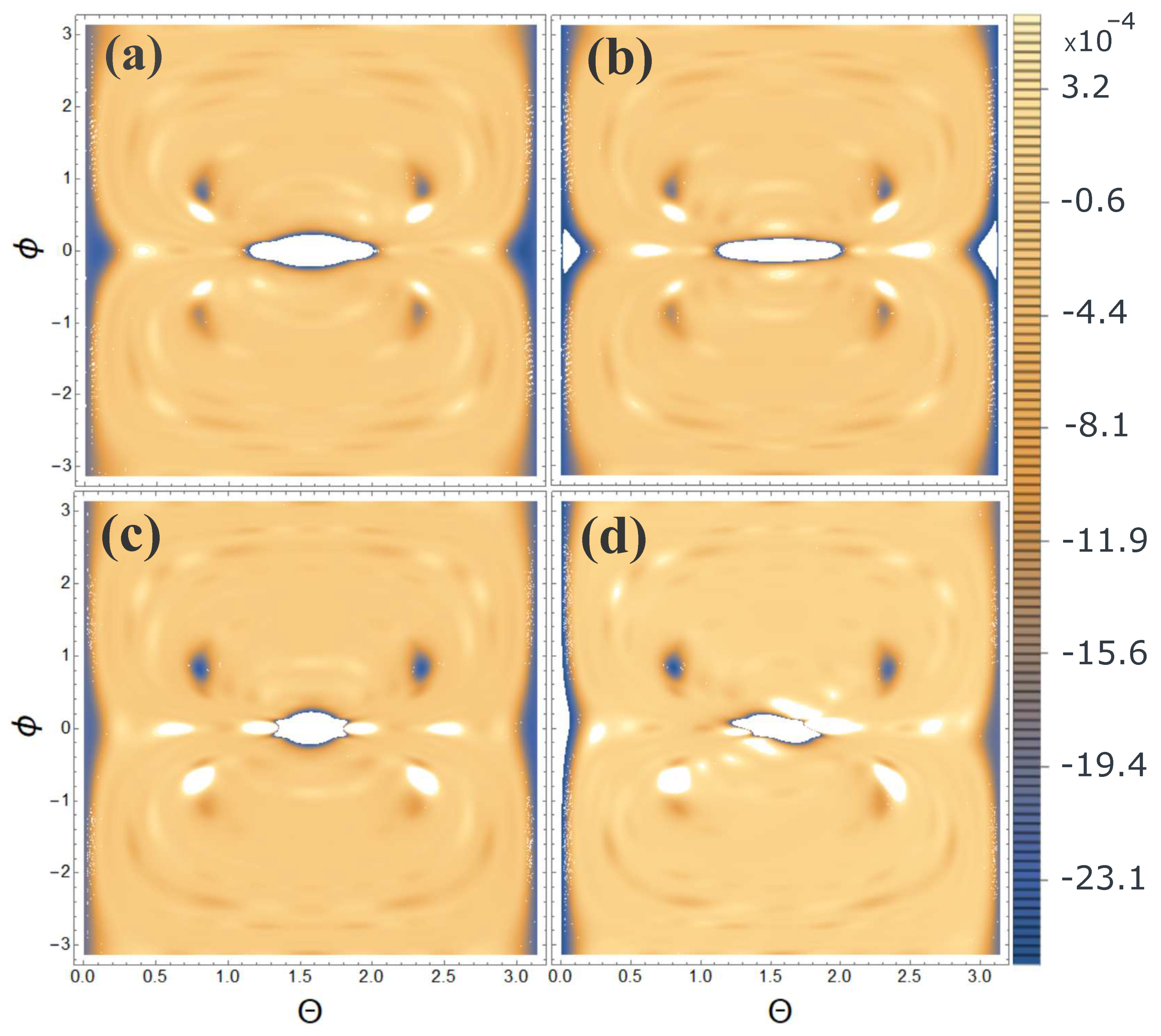
From Figure 5, Figure 6, Figure 7 and Figure 8 it can be seen that the effect of the orientation of N V centers is indeed present, despite the fact that the atomic composition and overall structure are preserved. Although this effect is not significant in relation to the main diffraction peaks (white spots on the 2D map). In order for this effect to be more noticeable and the effect of the orientation of N V centers to be clearly visible, it is necessary to consider not the scattering spectrum itself, but the relative contribution of the scattering spectrum of the diamond lattice (without N V centers) and oriented N V centers, normalized to the maximum value of the spectrum, i.e., δ = d ε d Ω k ) N V d ε d Ω k / d ε d Ω k m a x . The calculation results are presented in Figure 9.
From Figure 9 it is clearly seen that there are differences in the scattering spectra with different orientations. These differences are clearly visible and may indicate the orientation of N V centers in the diamond structure.
In these calculations, we considered the pulse to be ultrashort and took into account the pulse duration parameter τ . If we consider the momentum to be infinitely large τ and take into account only the coherent term in Eq. (2) then it will coincide with the previously well-known expression in the theory of diffraction analysis. Similar calculations were carried out, but at τ it turned out that the error in using the previously known expression and the above calculations using Eq. (2) large. This error is significantly larger than the studied effect of the orientation of N V centers. Thus, when using attosecond pulses, when studying the effect of orientation of N V centers in the diamond structure from XRD theory, it is necessary to use the expression Eq. (2).

3. Discussion and Conclusions

Thus, two important results were obtained in this work. The first result confirms the use of this theory (where the pulse duration is taken into account) and the large error of the previously developed and widely used theory (where the pulse duration is not taken into account) when using attosecond pulses. The second conclusion is the ability to determine the orientation of N V centers in the structure of the diamond lattice from scattering spectra.
In principle, when using ultrashort pulses, it is possible not only to determine the orientation of N V centers, but also to determine the distances between planes with N V centers. Indeed, if we analyze the parameter γ i , j ( p 0 , p τ ) , then we can conclude that diffraction occurs when USP is scattered by atoms that are located inside space with length c τ . Thus, by manipulating the pulse duration, you can see that when the first and second planes begin to diffract, the spacing between the planes will be c τ . Likewise with a large number of planes. This technique for studying the structure of diamond with N V centers is promising and will require additional study in the future.

Author Contributions

Conceptualization, D.M. and M.E.; methodology, D.M. and V.M.; software, D.M., E.G., M.B. and K.A.; validation, D.M.; formal analysis, D.M. and M.E.; writing—original draft preparation, D.M. and M.E.; writing—review and editing, D.M.; project administration, D.M. and M.E. All authors have read and agreed to the published version of the manuscript.

Funding

The research was supported by grants from the Russian Science Foundation, No. 23-12-20014; state assignment of the Russian Federation, No. FSRU-2021-0008.

Institutional Review Board Statement

Not applicable.

Informed Consent Statement

Not applicable.

Data Availability Statement

Request to corresponding author of this article.

Conflicts of Interest

The authors declare no conflict of interest.

References

  1. Jones, N. Crystallography: Atomic secrets. Nature 2018, 505, 602–603. [Google Scholar] [CrossRef] [PubMed]
  2. Benediktovich, A.; Feranchuk, I.; Ulyanenkov, A. Theoretical Concepts of X-Ray Nanoscale Analysis; Springer: Berlin/Heidelberg, Germany, 2014. [Google Scholar]
  3. Eseev, M.K.; Matveev, V.I.; Makarov, D.N. Diagnostics of Nanosystems with the Use of Ultrashort X-Ray Pulses: Theory and Experiment (Brief Review). JETP Lett. 2021, 114, 387–405. [Google Scholar] [CrossRef]
  4. Krausz, F.; Ivanov, M. Attosecond physics. Rev. Mod. Phys. 2009, 81, 163. [Google Scholar] [CrossRef]
  5. Dixit, G.; Vendrell, O.; Santra, R. Imaging electronic quantum motion with light. PNAS 2012, 109, 11636–11640. [Google Scholar] [CrossRef] [PubMed]
  6. Calegari, F.; Sansone, G.; Stagira, S.; Vozzi, C.; Nisoli, M. Advances in attosecond science. J. Phys. B: At. Mol. Opt. Phys. 2016, 49, 062001. [Google Scholar] [CrossRef]
  7. Kraus, P.M.; Zürch, M.; Cushing, S.K.; Neumark, D.M.; Leone, S.R. The ultrafast X-ray spectroscopic revolution in chemical dynamics. Nature Reviews Chemistry 2018, 2, 82–94. [Google Scholar] [CrossRef]
  8. Peng, P.; Marceau, C.; Villeneuve, D.M. Attosecond imaging of molecules using high harmonic spectroscopy. Nature Reviews Physics 2019, 1, 144–155. [Google Scholar] [CrossRef]
  9. Schoenlein, R.; Elsaesser, T.; Holldack, K.; Huang, Z.; Kapteyn, H.; Murnane, M.; Woerner, M. Recent advances in ultrafast X-ray sources. Philos. Trans. R. Soc. A 2019, 377, 20180384. [Google Scholar] [CrossRef]
  10. Duris, J.; Li, S.; Driver, T.; Champenois, E.G.; et al. Tunable isolated attosecond X-ray pulses with gigawatt peak power from a free-electron laser. Nature Photonics 2020, 14, 30–36. [Google Scholar] [CrossRef]
  11. Maroju, P.K.; Cesare Grazioli, M. Di, F.; et al. Attosecond pulse shaping using a seeded free-electron laser. Nature 2020, 578, 386–391. [Google Scholar] [CrossRef]
  12. D.Dunning.; Mcneil, B.; Thompson, N. Few-Cycle Pulse Generation in an X-Ray Free-Electron Laser. Phys. Rev. Lett. 2013, 110, 104801. [CrossRef] [PubMed]
  13. Mukamel, S.; Healion, D.; Zhang, Y.; Biggs, J.D. Multidimensional attosecond resonant X-ray spectroscopy of molecules: lessons from the optical regime. Annu. Rev. Phys. Chem. 2013, 64, 101–127. [Google Scholar] [CrossRef] [PubMed]
  14. Balasubramanian, G.; I.Y.Chan.; Kolesov, R.; Al-Hmoud, M.; Tisler, J.; et al. Nanoscale imaging magnetometry with diamond spins under ambient conditions. Nature 2008, 455, 648–651. [CrossRef] [PubMed]
  15. Doherty, M.W.; Manson, N.B.; Delaney, P.; Jelezko, F.; Wrachtrup, J.; Hollenberg, L.C. The nitrogen-vacancy colour centre in diamond. Physics Reports 2013, 528, 1–45. [Google Scholar] [CrossRef]
  16. Eseev, M.; Kuziv, I.; Kostin, A.; Meshkov, I.; Sidorin, A.; Orlov, O. Investigation of Nitrogen and Vacancy Defects in Synthetic Diamond Plates by Positron Annihilation Spectroscopy. Materials 2023, 16, 203. [Google Scholar] [CrossRef]
  17. Barry, J.; Schloss, J.; Bauch, E.; Turner, M.; Hart, C.; Pham, L.; Walsworth, R. Sensitivity optimization for NV-diamond magnetometry. Rev. Mod. Phys. 2020, 92, 015004. [Google Scholar] [CrossRef]
  18. Mrozek, M.; Schabikowski, M.; Mitura-Nowak, M.; Lekki, J.; Marszałek, M.; Wojciechowski, A.; Gawlik, W. Nitrogen-289 Vacancy Color Centers Created by Proton Implantation in a Diamond. Materials 2021, 14, 833. [Google Scholar] [CrossRef] [PubMed]
  19. Popov, V.; Podlesny, S.; Kartashov, I.; Kupriyanov, I.; Palyanov, Y. Long dephasing time of NV center spins in diamond layers formed by hot ion implantation and high pressure high temperature annealing. Diamond and Related Materials 2021, 120, 108675. [Google Scholar] [CrossRef]
  20. Pham, L.; N.Bar-Gill.; et al, D.S. Enhanced metrology using preferential orientation of nitrogen-vacancy centers in diamond. Phys. Rev. B 2012, 86, 121202(R). [CrossRef]
  21. Henriksen, N.E.; Moller, K.B. On the Theory of Time-Resolved X-ray Diffraction. J. Phys. Chem. B 2008, 112, 558–567. [Google Scholar] [CrossRef]
  22. Astapenko, V.A.; Sakhno, E.V. Excitation of a quantum oscillator by short laser pulses. Applied Physics B 2020, 126, 23. [Google Scholar] [CrossRef]
  23. Rosmej, F.B.; Astapenko, V.A.; Lisitsa, V.S.; Li, X.D.; Khramov, E.S. Scattering of ultrashort laser pulses on “ion-sphere” in dense plasmas. Contrib. Plasma Phys. 2019, 59, 189–196. [Google Scholar] [CrossRef]
  24. Makarov, D.N. Quantum theory of scattering of ultrashort electromagnetic field pulses by polyatomic structures. Optics Express 2019, 27, 31989–32008. [Google Scholar] [CrossRef] [PubMed]
  25. Eseev, M.K.; Goshev, A.A.; Makarov, D.N. Scattering of Ultrashort X-ray Pulses by Various Nanosystems. Nanomaterials 2020, 10, 1355. [Google Scholar] [CrossRef] [PubMed]
  26. Eseev, M.K.; Goshev, A.A.; Makarova, K.A.; Makarov, D.N. X-ray diffraction analysis of matter taking into account the second harmonic in the scattering of powerful ultrashort pulses of an electromagnetic field. Scientific Reports 2021, 11, 3571. [Google Scholar] [CrossRef] [PubMed]
  27. Eseev, M.; Makarova, K.; Makarov, D. Scattering of Ultrashort X-ray Pulses on Diamonds with NV Centers. Crystals 2022, 12, 1417. [Google Scholar] [CrossRef]
  28. Moller, K.B.; Henriksen, N.E. Time-resolved x-ray diffraction: The dynamics of the chemical bond. Struc. Bond. 2012, 142, 185. [Google Scholar]
  29. Tanaka, S.; Chernyak, V.; Mukamel, S. Time-resolved x-ray spectroscopies: Nonlinear response functions and liouville-space pathways. Phys. Rev. A 2001, 63, 63405–63419. [Google Scholar] [CrossRef]
  30. Dixit, G.; Slowik, J.; Santra, R. Proposed Imaging of the Ultrafast Electronic Motion in Samples using X-Ray Phase Contrast. Phys. Rev. Lett. 2013, 110, 137403. [Google Scholar] [CrossRef]
  31. James, R.W. The Optical Principles of the Diffraction of X-rays (Ox Bow); Ox Bow Press: Woodbridge, CO, USA, 1982. [Google Scholar]
  32. Makarov, D.; Kharlamova, A. Scattering of X-ray Ultrashort Pulses by Complex Polyatomic Structures. Int. J. Mol. Sci. 2022, 23, 163. [Google Scholar] [CrossRef]
  33. Makarov, D.N.; Makarova, K.A.; Kharlamova, A.A. Specificity of scattering of ultrashort laser pulses by molecules with polyatomic structure. Scientific Reports 2022, 12, 1–9. [Google Scholar] [CrossRef] [PubMed]
  34. Makarov, D.; Kharlamova, A. Scattering of Attosecond Laser Pulses on a DNA Molecule during Its Nicking and Bending. Int. J. Mol. Sci. 2023, 24, 15574. [Google Scholar] [CrossRef] [PubMed]
  35. Makarov, D.N.; Eseev, M.K.; Makarova, K.A. Analytical wave function of an atomic electron under the action of a powerful ultrashort electromagnetic field pulse. Optics Letters 2019, 44, 3042–3045. [Google Scholar] [CrossRef] [PubMed]
  36. Salvat, F.; Martnez, J.D.; Mayol, R.; Parellada, J. Analytical Dirac-Hartree-Fock-Slater screening function for atoms (Z = 1-92). Phys. Rev. A 1987, 36, 467–474. [Google Scholar] [CrossRef]
  37. Lin, Q.; Zheng, J.; Becker, W. Subcycle pulsed focused vector beams. Phys. Rev. Lett. 2006, 97, 253902. [Google Scholar] [CrossRef]
Figure 1. USP incident on a diamond structure with oriented N V centers (orientation 1) is presented. The diamond structure is defined by 16 unit cells of diamond ( 4 × 4 ). Blue circles are carbon atoms, purple circles are nitrogen atoms, and yellow circles are vacancies. On the right is a unit cell with N V center with orientation 1.
Preprints 91300 g001
Figure 2. The same as in Figure 1, but with orientation 2.
Preprints 91300 g002
Figure 3. The same as in Figure 1, but with orientation 3.
Preprints 91300 g003
Figure 4. The same as in Figure 1, but with orientation 4.
Preprints 91300 g004
Figure 5. Scattering spectra are presented for orientation 1, see Figure 1: (a) 3D scattering spectra, where the main peak is directed in the direction of the incident pulse; (b) contour plot in a spherical coordinate system, where θ and ϕ are spherical angles, where ϕ is the azimuthal angle, and the z axis is directed perpendicularly upward to the lattice plane Figure 1.
Preprints 91300 g005
Figure 6. Same as in Figure 5, but for orientation 2, see Figure 2.
Preprints 91300 g006
Figure 7. Same as in Figure 5, but for orientation 3, see Figure 3.
Preprints 91300 g007
Figure 8. Same as in Figure 5, but for orientation 4, see Figure 4.
Preprints 91300 g008
Figure 9. The calculation of the value δ = d ε d Ω k ) N V d ε d Ω k / d ε d Ω k m a x : (a) in the case of orientation 1, see. Figure 1, (b) in case of orientation 2, see Figure 2, (c) in case of orientation 3, see Figure 3, (d) in case of orientation 4, see Figure 4.
Preprints 91300 g009
Disclaimer/Publisher’s Note: The statements, opinions and data contained in all publications are solely those of the individual author(s) and contributor(s) and not of MDPI and/or the editor(s). MDPI and/or the editor(s) disclaim responsibility for any injury to people or property resulting from any ideas, methods, instructions or products referred to in the content.
Copyright: This open access article is published under a Creative Commons CC BY 4.0 license, which permit the free download, distribution, and reuse, provided that the author and preprint are cited in any reuse.
Prerpints.org logo

Preprints.org is a free preprint server supported by MDPI in Basel, Switzerland.

Subscribe

© 2024 MDPI (Basel, Switzerland) unless otherwise stated