1. Introduction
For long-term and secure utilization of dental implants, it is essential to recognize that factors contributing to damage in implant technology emerge from both biological and mechanical aspects [
5]. In addition to damages caused by biological factors, mechanical factors, such as excessive forces, improper occlusion, or suboptimal implant design, can result in mechanical damage, which may involve component fractures, implant loosening, or implant breakage [5-7]. Apart from biological factors, mechanical damage in the long-term use of dental implants can be minimized through an optimized design that reduces stress distribution. It is known that the fracture of implant components is directly associated with the concentration of stress around the implant system when subjected to repeated masticatory forces. Stress concentration arises at implant cross-sectional changes or geometric irregularities, reducing implant system resistance to fatigue fractures and leading to biomechanical implant failure. Stress distribution around an implant depends on various biomechanical factors, including design, load type, material properties, surface roughness, bone quality, and implant-bone interaction. Excessive loading can lead to direct stress transmission from the implant to bone, causing destructive damage in the bone tissues.[7-9] Therefore, the longevity of dental implants is significantly influenced by the implant material and its geometry, as well as the optimization of biomechanical factors to ensure smooth stress transmission from the implant to the bone, which is crucial for long-term success.
Titanium alloys are widely prevalent and crucial in the construction of dental implants.[
11] Among titanium alloys, Ti6Al4V alloy is preferentially chosen for dental implant construction due to its excellent biocompatibility, corrosion resistance, mechanical strength, and ability to osseointegrate with bone tissue, making it an ideal material for long-lasting and successful dental implant applications. Additionally, In light of the growing demand for customized dental implants, the meticulous design and subsequent finite element analysis of patient-specific implants prior to fabrication have gained paramount importance.
In this study, two types of Ti6Al4V implants were developed and their design parameters were optimized to enhance fracture resistance and prolong the service life of Ti6Al4V implants under static loading conditions. Subsequently, 100 N force was applied to these implant designs and then failure analysis was performed [
12,
15]. Consequently, the Ti6Al4V implant model exhibiting the most favorable biomechanical performance across all static loading conditions was identified.
While dynamic loading tests are more representative of real-world conditions, static loading remains a crucial component of materials testing. It offers a controlled and simplified environment for understanding fundamental material properties, and this understanding is vital when interpreting the more complex results obtained under dynamic loading conditions. In this study, the behavior of dental implant models under various static loading conditions was investigated.
The implant, abutment, and screw together form a mechanical structure of dental implants. In some studies, only a part of the dental implant system, especially the implant part, has been examined [
9,
14]. In this study, the stress and strain values of the implant, screw and abutment complete system under certain loads were examined. This is because deformation of any of these parts negatively affects the operation of the dental implant system in real life. In addition, the condition in one part may cause problems in other parts.
2. Materials and Methods
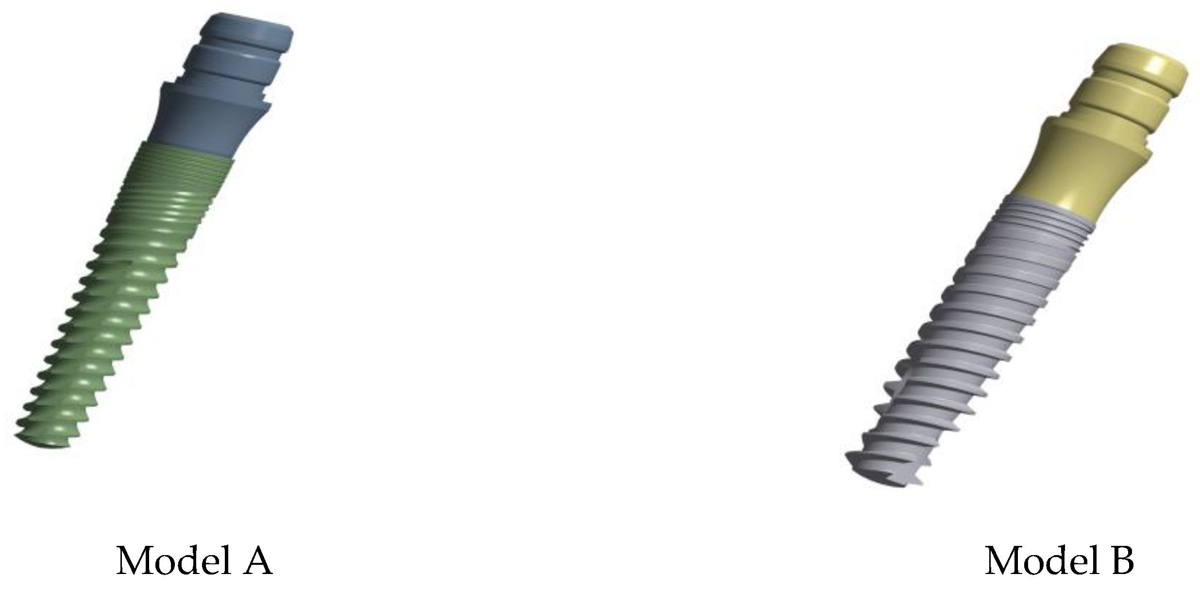
In this study, CAD software (Ansys Spaceclaim 2022 R2) was utilized to create 3D models of internally connected multi-part implant systems consisting of implants and abutments in various dimensions as shown in
Figure 1. The models were assumed to have linearly elastic, homogeneous, and isotropic materials, with their corresponding mechanical properties detailed in
Table 1.
As illustrated in the
Figure 2, two distinct implant models were created by altering both the implant diameter and the abutment diameter.
The implant diameters of 3.25 mm and the abutment diameters of 3.8 mm were used in this study. The designs were created by combining distinct dimensions provided in
Figure 3 in a physically suitable manner, resulting in the acquisition of two combinations of implant designs.
To comply with the stipulations of the adopted standard (ISO 14801), depicted in
Figure 4, the implant systems must be secured in a stable clamping holder, commonly chosen as a steel block. Alternatively, before fixation, they may be embedded in an implant holder characterized by a modulus of elasticity exceeding 3 GPa, in line with the materials recommended in the literature [
15]. Lastly, once the fixation procedure is established, the abutment, which is screwed onto the implant, is subjected to a 30° oblique force, as recommended by the relevant standard. In this investigation, the implants, abutments, and rectangular prism-shaped implant holders were assembled using CAD software. Subsequently, the assembly was exported to ANSYS Workbench 2022 R2 (ANSYS, Inc., USA). FEA technique provides dentists with various biomechanical properties, including stress transfer from implant to surrounding bone, micromotions, deformations of the implant system and bone tissue under different biting forces, effects of load types and magnitudes on the implant system, and influences of implant design parameters on stress transmission. Additionally, FEA allows for the determination of these biomechanical properties for any uniquely designed dental implant tailored to an individual.
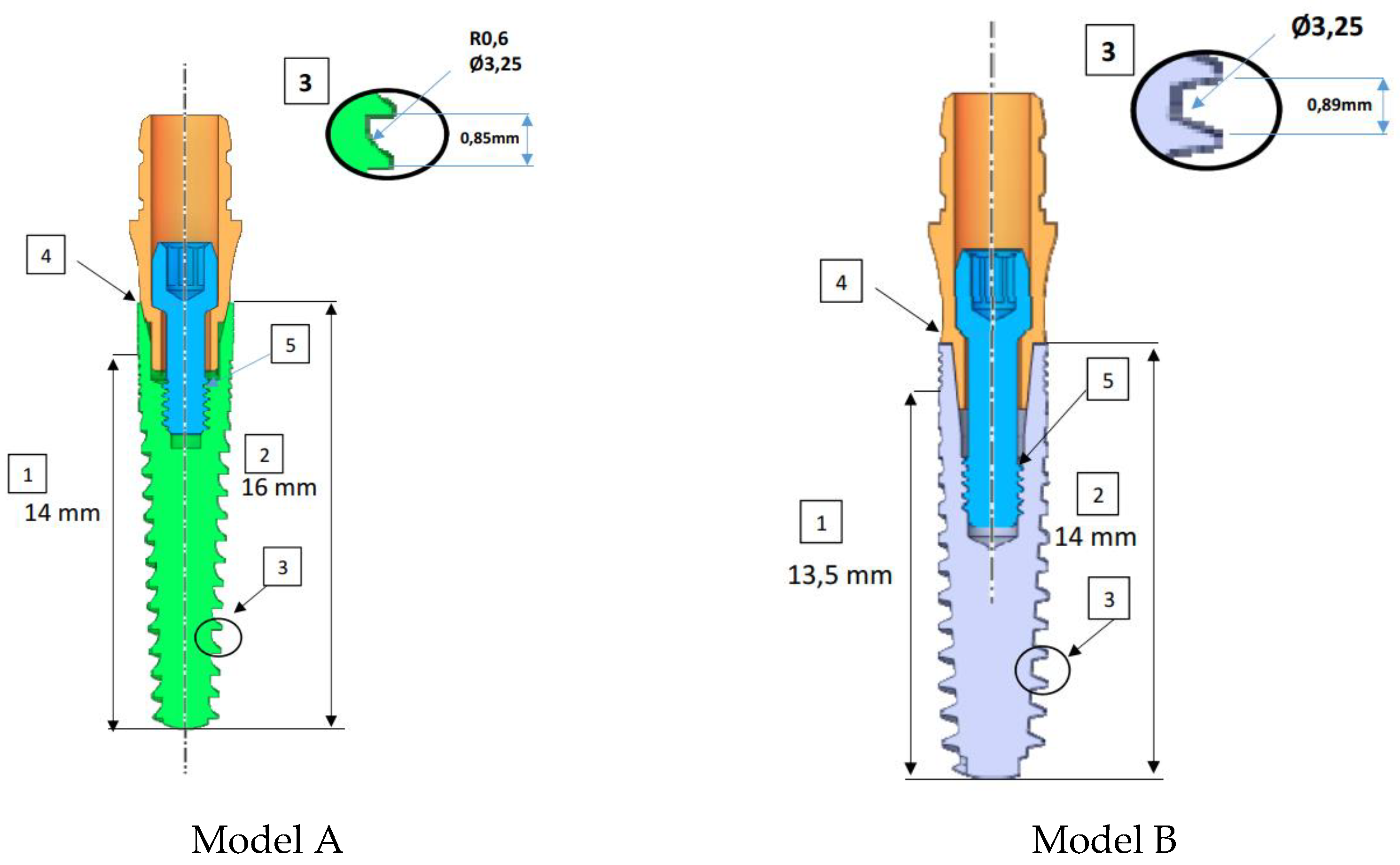
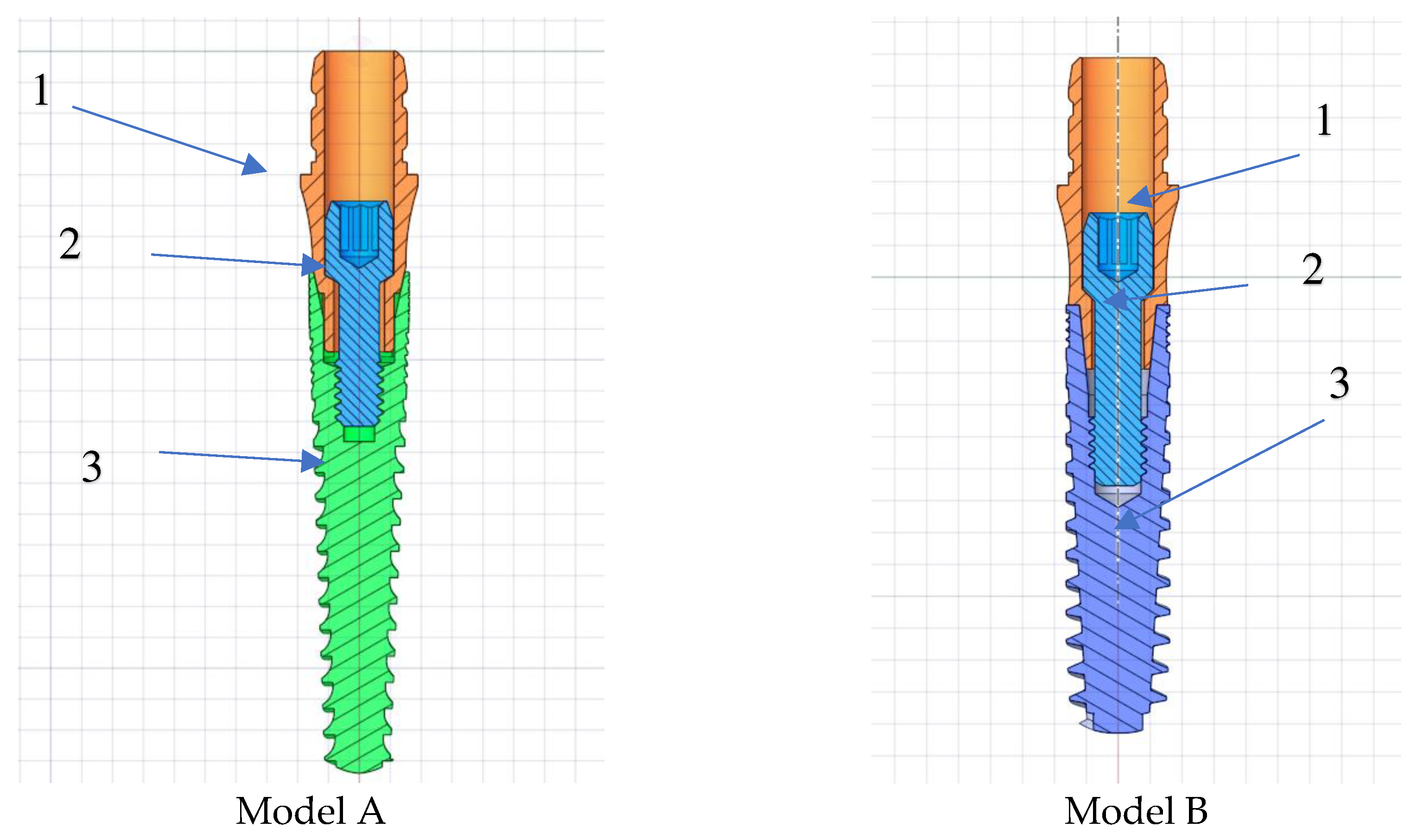
The design differences between Model A and Model B are shown in
Figure 3. The implants have a length of 16.0 mm (model A), 14.0 mm (model B), featuring a non-threaded cylindrical neck with a height of 2.0 mm (model A) to 1.5mm (model B) and a threaded part with a height of 14.0 mm (model A) to 12.00 mm (model B). In the implant tooth geometries indicated with number 3, the screw pitch is increased in model B in comparison to model A. In region 4, the abutment conical connection has been strengthened and the wall thickness has been increased. The wall thickness of the implant in the area near the abutment increases from the minimum value of 0.15 mm to 0.40 mm by changing the taper angle and shape of the abutment and implant. This change can be seen in the area indicated by number 4 in
Figure 3. In region 5, the screw length extends and the thread diameter increases from 1.3 mm to 1.45 mm.
Figure 3.
The differences in the design of models A and B subjected to FEM analysis. The numbers in squares represent regions of interest.
Figure 3.
The differences in the design of models A and B subjected to FEM analysis. The numbers in squares represent regions of interest.
For this purpose, based on various studies considering a 100 N load within the range of normal bite forces, this study applied a 100 N load to the top surface of each design in both axial and 30° oblique directions using the finite element method, in accordance with ISO 14801. To create meshes with tetrahedral solid elements, geometries were imported into the finite element software Ansys Workbench 2022 R2. The total number of nodes and elements of each model is shown in
Table 2.
Isotropic and linear elastic properties were used as the element structure. Moreover, the strain results, serving as a suitable convergence analysis criterion in the FEA model, were brought to convergence tolerance 1x10
-8 to align with potential real-world applications. As a result, the required mesh resolutions were achieved through multiple refinement processes for all models as shown in
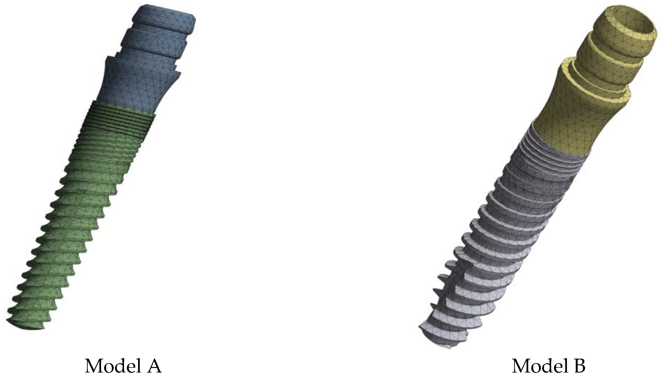
Figure 4.
The stress results in each analysis is presented in von-Mises equivalent stresses, representing the comprehensive stress state at a given point. This enables accurate determination of critical stress concentration regions in the models subjected to the respective loads.
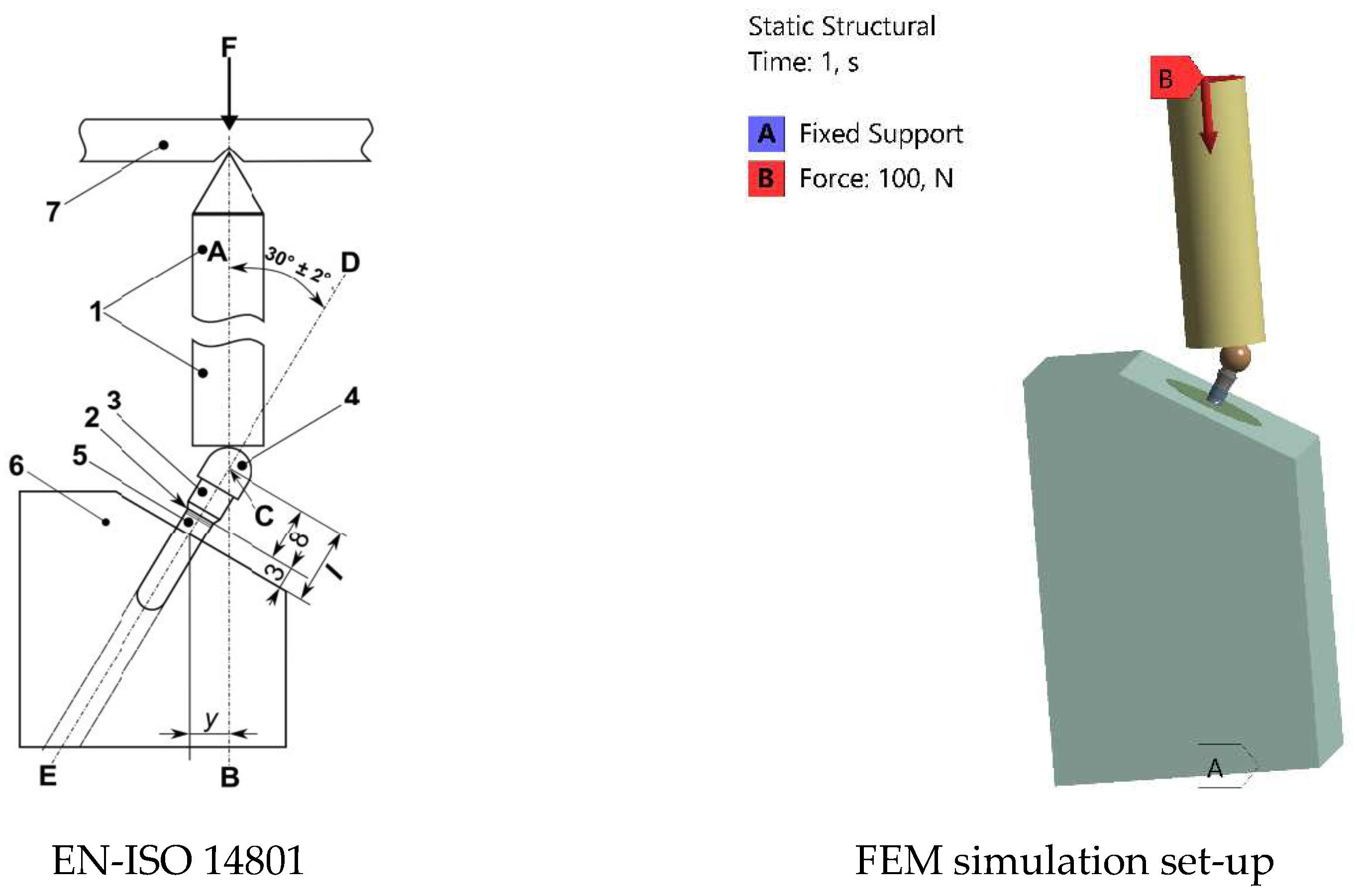
Figure 6 provides a concise representation of the FEA conditions, illustrating loading conditions in accordance with the relevant standard. Components 2, 3, and 5 depicted in
Figure 3 represent the implant, made of titanium, while parts 1, 4, and 6 are identified as steel materials. Furthermore, the position of the intersection (C) between the loading axis (Line AB) and the axis of the endosseous dental implant (Line DE) is precisely defined, allowing the measurement or calculation of the moment arm (y) [
1].
Figure 4.
Mesh Model of Dental Implants.
Figure 4.
Mesh Model of Dental Implants.
The types of element used in the ANSYS software are given in
Figure 5. While the finite element model was formed, Shell181 (linear shape function) with middle nodes closed, Solid186 element, Solid187 element and B Shell181 is a degree (linear) type of the element must be at the point of translation and rotation in X, Y and Z axis with 4 nodes and 6 degrees of freedom in each node point (Fig. 5-a). Solid186 is a type of an element, in which each node at the point of the X, Y, Z axes as displacement and rotation has 6 degrees of freedom, showing 20 node-point, and is of second order type (quadratic) (Fig. 5-b). Solid187 is a second order type element, too, with three degrees of freedom in each axis. The element has 4 surfaces and 10 nodes (Fig. 5-c).
Figure 5.
Element Types of Mesh Model.
Figure 5.
Element Types of Mesh Model.
Figure 6.
Loading geometry according to EN-ISO 14801 standard, illustrated as follows: 1. Loading device, 2. Nominal bone level, 3. Abutment, 4. Hemispherical loading member, 5. Dental implant body, 6. Specimen holder, F. Loading force, C. Loading center, AB. Loading axis, DE. Dental implant axis.
Figure 6.
Loading geometry according to EN-ISO 14801 standard, illustrated as follows: 1. Loading device, 2. Nominal bone level, 3. Abutment, 4. Hemispherical loading member, 5. Dental implant body, 6. Specimen holder, F. Loading force, C. Loading center, AB. Loading axis, DE. Dental implant axis.
3. Results and Discussion
3.1. Stress Analysis
Similar to previous studies [
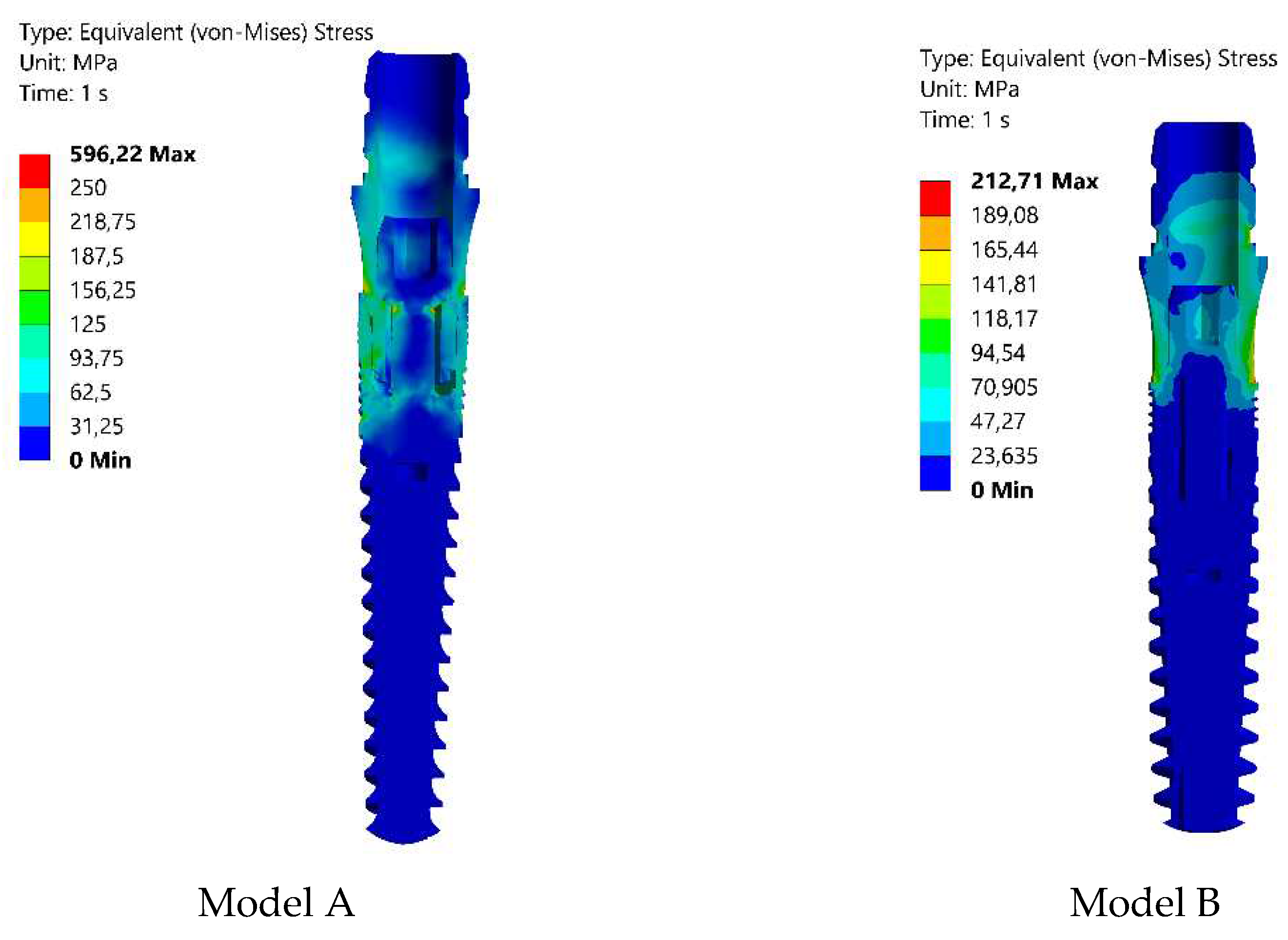
2], the highest von-Mises stress values in this work were identified at the first and second threads near the implant heads (see Fig. 7). Consequently, the performance of implant systems (implant and abutment) was assessed based on stress concentrations in these threads. The von-Mises stress results of implants were categorized by their diameters, assuming that the implant diameter is a crucial factor in the design process for ensuring smooth stress transmission. Smooth stress transition is crucial for implants to meet patients' treatment expectations and align with bone tissue for load resistance. Achieving this requires meticulous design, fostering improved physical surface interaction between the bone and the implant for optimal stress distribution within physiological limits. Based on the findings, there is a tendency for von-Mises stresses to decrease with an increase in taper angles. Furthermore, an increase in taper angle led to higher values of wall thickness. The distribution of stress on various surfaces is illustrated by the von-Mises stress (Fig. 7), indicating which areas were more prone to stress. The highest von-Mises stresses are observed on the second thread of the implants in Model A. As a result of the finite element analyses, the maximum equivalent stresses are found to be 596.22 MPa and 212.71 MPa, respectively. It is evident that Model B demonstrates reduced von-Mises values in contrast to Model A, with stress distribution across a broader area. The internal screw seems to be less impacted by mechanical stresses. This result in Model B aligns with material properties, because the obtained stress value is significantly below the yield strength of Ti-6Al-4V (Grade V Annealed), which is approximately 880 MPa. Consequently, modifications were implemented to the implant, abutment, and screw depicted in
Figure 2 for Model B. This led to a notable reduction in the maximum equivalent stress value in Model B to 212.71 MPa, signifying a substantial enhancement in the implant's durability. In a finite element analysis of the mechanical failure of implants, it was reported that implant diameter and wall thickness are influential parameters in stress reduction [
3]. The decrease in the conical angle in the abutment conical area increased the wall thickness, which causes a decrease in the stress values, and the stress values decreases with the increase in the implant diameter. In addition, increasing the spacing and decreasing the taper angle of the implant screw threads reduces the stress. Accordingly, the minimum diameter of the connection screw was increased from 1.3 mm to 1.45 mm and this change significantly reduced stress. This implies that the reduction in stress improves the implant's capacity to withstand bending and torsional loads, thereby preventing premature failure. Similar to the findings of Satyanarayana et al. [
10], the choice of abutment type was identified to significantly influence stress distribution. This is attributed to variations in load transfer mechanisms and differences in the contact area size between the abutment and the implant. According to the studies of M. Jeng et al., the increase in wall thickness provides a significant stress reduction in the implant, abutment and screw [16-17]. We can evaluate that increasing the wall thickness from 0.15 mm to 0.40 mm is an important factor in reducing the stress.
Figure 7.
von-Mises stress distributions on the implants designed as Model A and B (load 100 N).
Figure 7.
von-Mises stress distributions on the implants designed as Model A and B (load 100 N).
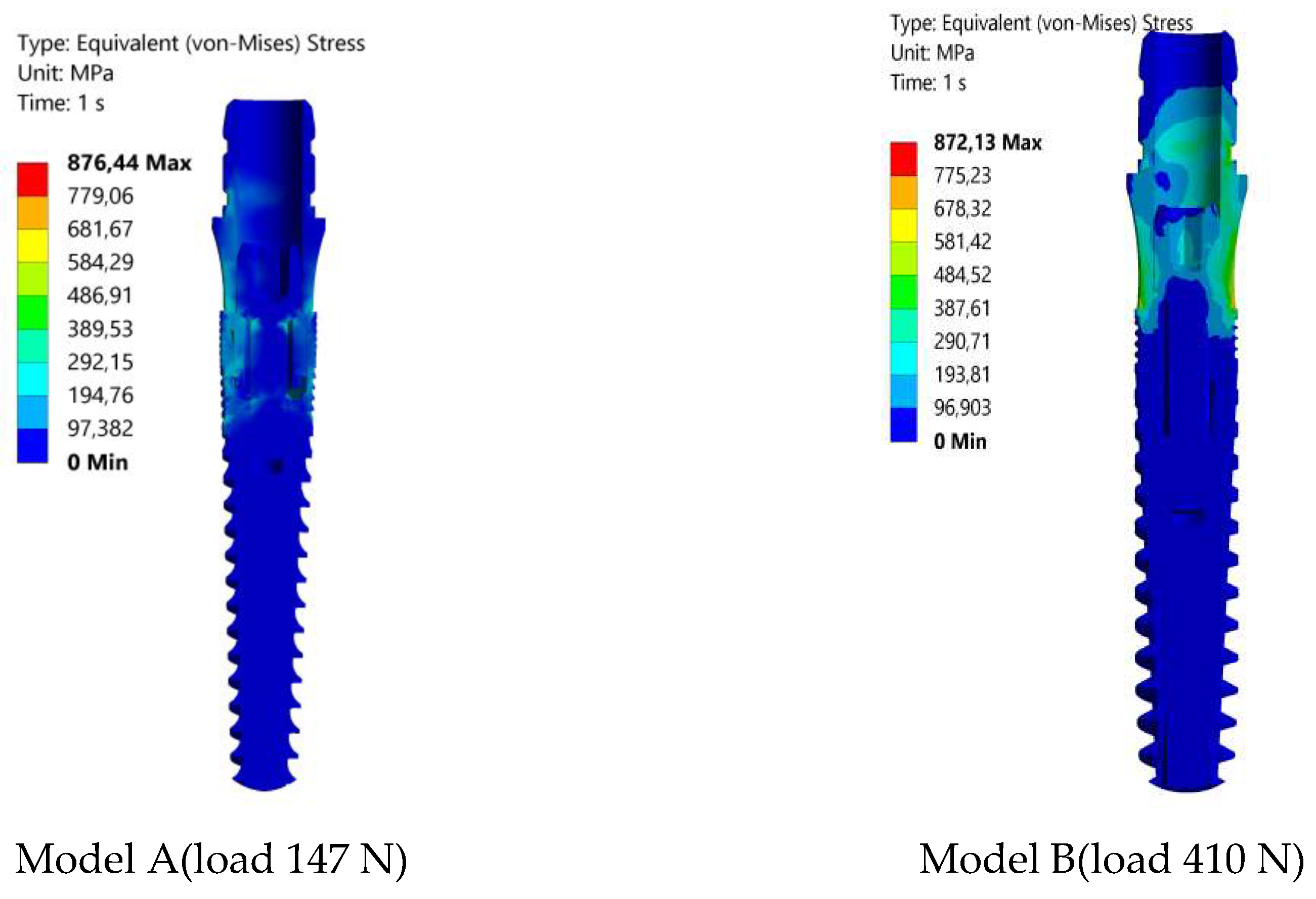
Further finite element analyses were conducted on Model A and Model B as the oblique loads gradually increased until reaching the maximum critical load, initiating implant yielding. As indicated in
Figure 8, the yield stress was reached at load values of 147 N for Model A and 410 N for Model B. Based on the obtained von Mises equivalent stress under static loading conditions, it was found that the implants undergo no plastic deformations up to these critical loads in the tested models.
3.2. Strain Analysis
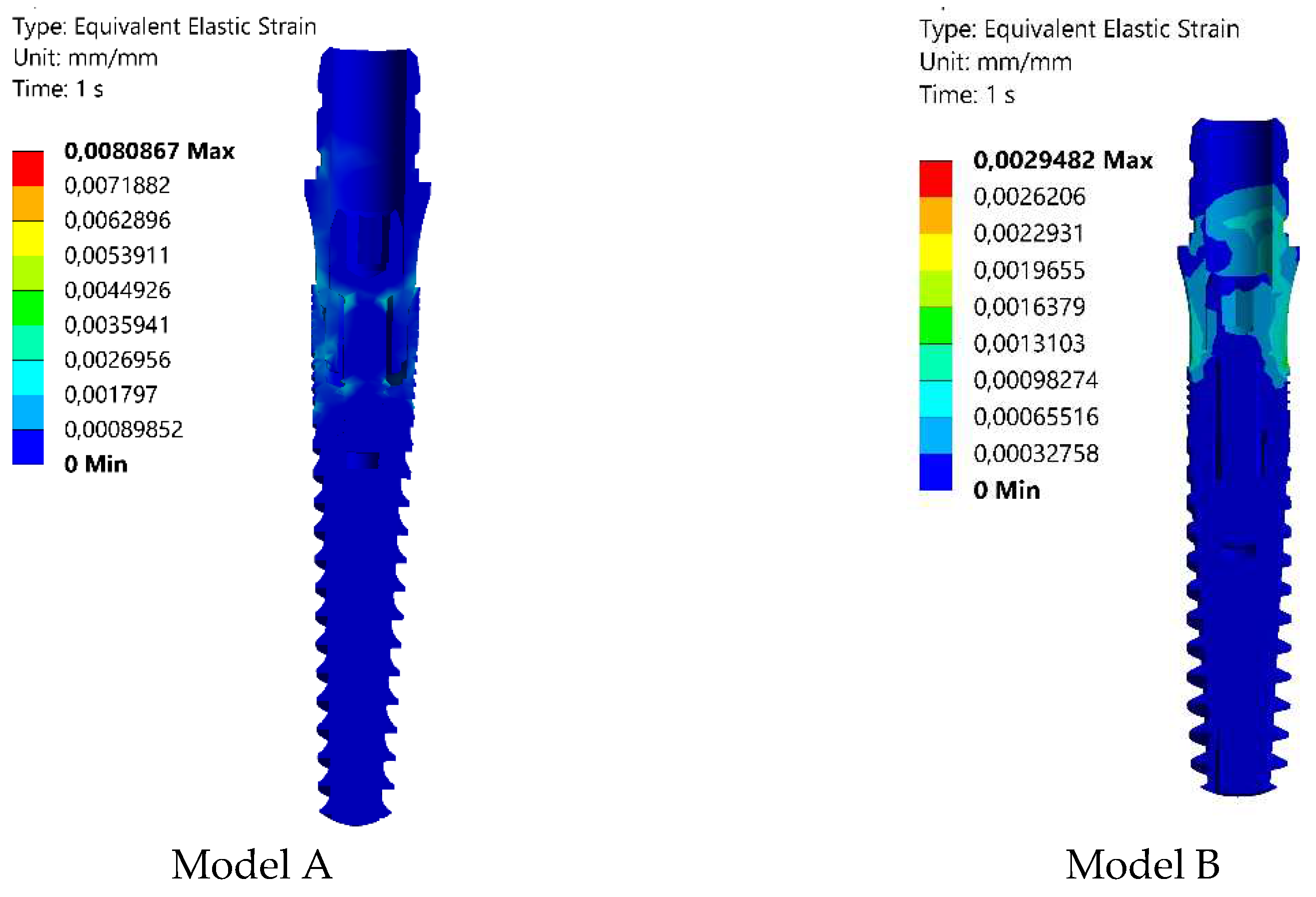
The Finite Element Analysis (FEA) obtained strains intervals within the elasticity of the modeled materials. The Elastic Equivalent strains are shown in
Figure 8. The convergence criterion was set to less than 1% in the changes in the total deformation energy of all the elements [
14]. The decrease in Elastic Equivalent strain indicates that the model B implant undergoes less deformation than the model A implant. In alignment with the research conducted by D. Darvish et al. [
13], this present study similarly observed a reduction in strain corresponding to a decrease in stress. According to the literature, the minimum and maximum equivalent elastic strain amounts should fall within the range of 0.0015 to 0.0030 to create an optimal environment for bone growth without the risk of fracture [
9]. The calculated strain value of 0.0029482 in model B satisfies this condition, as indicated in
Table 3.
Figure 8.
Strain (Equivalent Elastic Strain) distributions obtained in Model A and B under 100 N applied load.
Figure 8.
Strain (Equivalent Elastic Strain) distributions obtained in Model A and B under 100 N applied load.
4. Conclusion
The objective of this study was to identify essential design parameters for achieving an implant model with high fracture resistance and long-term stability. To fulfill this objective, diverse Ti-6Al-4V implant models of varying dimensions were created, and their stress-strain analyses were executed under common bite force (100 N) in accordance with ISO 14801. The findings and implications of this research can be summarized as follows:
The Ti-6Al-4V implant model B, featuring a diameter of 3.25 mm, abutment diameter of 3.80 mm, and taper angle of 11.4°, demonstrates the minimum stress concentration, measured at 212.71 MPa von-Mises stress, when subjected to a daily biting force of 100 N.
Decreasing the taper angle and increasing the screw diameter causes the maximum amount of the stress on the dental implant to decrease.
Optimizing the implant design is highly effective in mitigating stress distribution.
In the design of Model B, the deformation (elastic equivalent strain) decreased by approximately 63%, making it more practical and consistent with actual applications, as confirmed by convergence analysis in the FEA model.
Under static loading, the critical loads, where no yielding or fracture occurred for the designed Model A and B, were found to be 147 N and 410 N, respectively.
It is planned to perform dynamic analyzes in model B in the continuation of this study. A comparison will be made with existing implants. The dental implant developed in Model B will be produced. Physical in vitro tests will be carried out. The finite element simulation results will be validated with these results. In order to apply the results in the newly developed model B, the necessary tests will be carried out according to two standards, i.e. Torsion Test ISO/TS 13498 and Cyclic Torsional Loading of Dental Implants ISO/TR 18130. The results will be compared with other models.
Author Contributions
Conceptualization,E.P.; methodology, E.P.; software, E.P; validation, E.P and I.O.; formal analysis, E.P., and I.O.; investigation, E.P. and I.O.; resources, E.P.; data curation, E.P. and I.O.; writing—original draft preparation, E.P., and I.O.; writing, review and editing, E.P., I.O., and T.G.,; visualization, E.P.; supervision, T.L.; All authors have read and agreed to the published version of the manuscript
Funding
Alexander von Humboldt Foundation 10. Round PSI.
Acknowledgments
The authors would like to thank the MarlaDT Engineering (Turkey), for providing implants model used for the biomechanical comparison.
Conflicts of Interest
The authors declare no conflict of interest.
References
- E. Menacho-Mendoza, R. Cedamanos-Cuenca, A. Díaz-Suyo; T Stress analysis and factor of safety in three dental implant systems by finite element analysis 2022. [CrossRef]
- F. Bayata, C.Yildiz; The effects of design parameters on mechanical failure of Ti-6Al-4V implants using finite element analysis, 2020. [CrossRef]
- D. Šarac, I. Atanasovska, S. Vulović, N. Mitrović, I. Tanasić; Numerical Study of the Effect of Dental Implant Inclination, 2017. [CrossRef]
- Tiossi R et al. Digital image correlation analysis on the influence of crown material in implant-supported prostheses on bone strain distribution., 2012. [CrossRef]
-
https://asm.matweb.com/search/SpecificMaterial.asp?bassnum=mtp641.
- X. Li, F. Dong. Three-dimensional finite element stress analysis of uneven-threaded ti dental implant , 2016, Corpus ID: 4888142.
- J. P. Geng, BDS, DrPH, MScD; W. Xu, BEng, PhD; K. B. C. Tan, BDS, MSD; G. R. Liu, PhD; Finite Element Analysis of an Osseointegrated Stepped Screw Dental Implant, 2004. [CrossRef]
- M. Geramizadeha, H. Katooziana, R. Amidb, M. Kadkhodazadehb; Finite Element Analysis of Dental Implants with and without Microthreads under Static and Dynamic Loading, 2017. [CrossRef]
- T. SV. Satyanarayana, R. Rai, E. Subramanyam, T. Illango, V. Mutyala, R. Akula; Finite element analysis of stress concentration between surface coated implants and non surface coated implants - An in vitro study, 2019. [CrossRef]
- D. Farronato, M. Manfredini, A. Stevanello, V. Campana,L. Azzi, M. Farronato; A Comparative 3D Finite Element Computational Study of Three Connections, 2019. [CrossRef]
- F. N. Büyük, E. Savran, F. Karpat; Review on finite element analysis of dental implants, 2022. [CrossRef]
- D. Darvish , S. Khorramymehr , M. Nikkhoo; Finite Element Analysis of the Effect of Dental Implants on Jaw Bone under Mechanical and Thermal Loading Conditions, 2021. [CrossRef]
- L. Paracchini at al..; Finite Element Analysis of a New Dental Implant Design Optimized for the Desirable Stress Distribution in the Surrounding Bone Region, 2020. [CrossRef]
- Y. Xiong at all.; Fatigue behavior and osseointegration of porous Ti-6Al-4V scaffolds with dense core for dental application, 2020. [CrossRef]
- ISO 14801:2016 Dentistry — Implants — Dynamic loading test for endosseous dental implant.
- B. S.H. Tonin at al.; The effect of abutment material stiffness on the mechanical behavior of dental implant assemblies: A 3D finite element study, 2023,. [CrossRef]
- M. Jeng,Y. Lin, C. Lin; Biomechanical Evaluation of the Effects of Implant Neck Wall Thickness and Abutment Screw Size, 2020,. [CrossRef]
|
Disclaimer/Publisher’s Note: The statements, opinions and data contained in all publications are solely those of the individual author(s) and contributor(s) and not of MDPI and/or the editor(s). MDPI and/or the editor(s) disclaim responsibility for any injury to people or property resulting from any ideas, methods, instructions or products referred to in the content. |
© 2023 by the authors. Licensee MDPI, Basel, Switzerland. This article is an open access article distributed under the terms and conditions of the Creative Commons Attribution (CC BY) license (http://creativecommons.org/licenses/by/4.0/).
