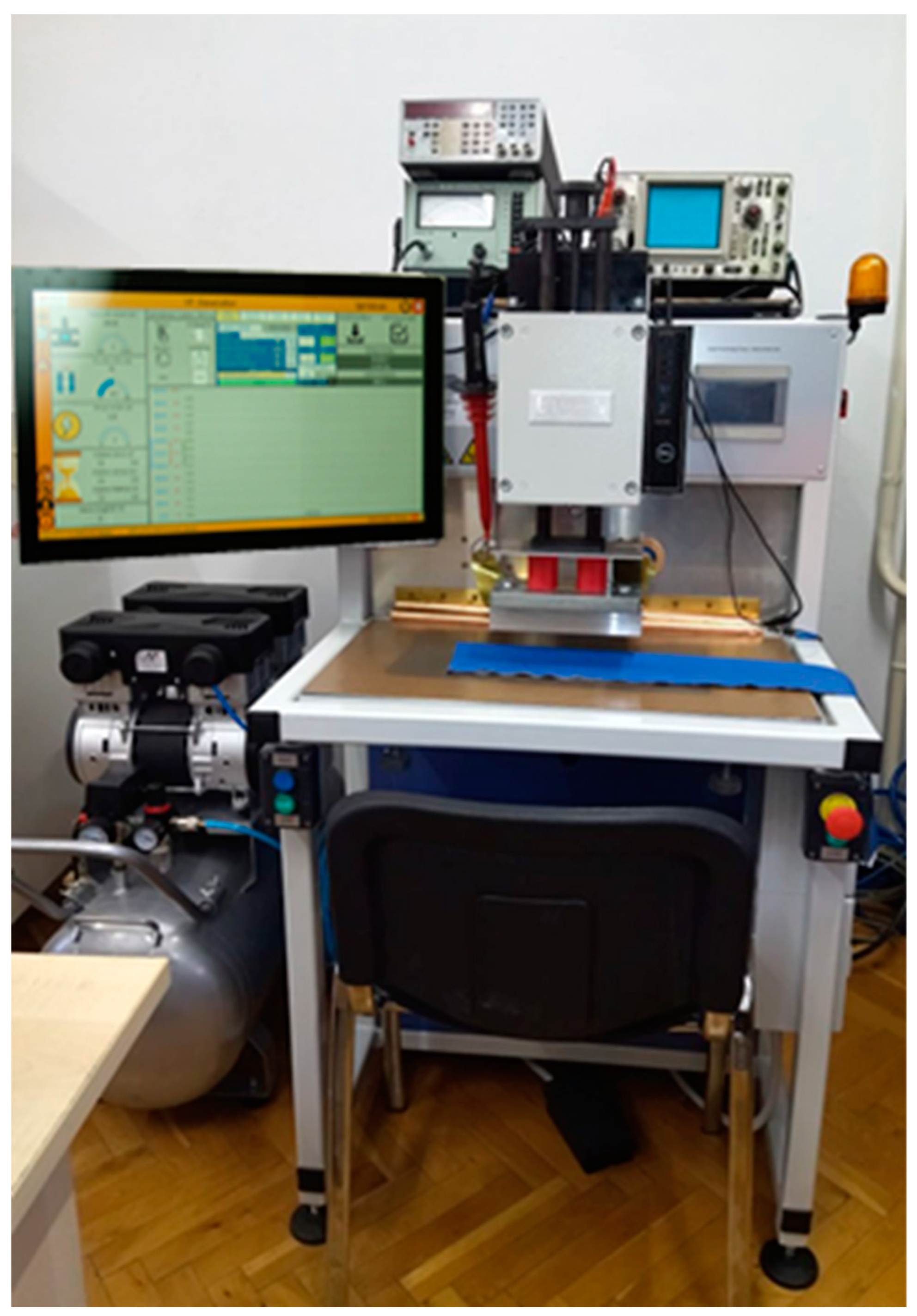
The use of high frequency (HF) electromagnetic field for welding parts of clothing is related to high technological techniques of welding, such as ultrasonic welding, welding using heat in the form of conduction and convection, and welding with infrared lasers. The aforementioned techniques are displacing the traditional techniques for joining clothing parts, namely sewing and gluing, due to their favourable characteristics such as lower energy consumption, high productivity and environmental awareness. They are characterised by exceptional strength of the produced welded joints, air and water impermeability and are used in almost all joining techniques in apparel technology.
The oldest available research paper on high frequency heating dates from 1944 and is titled “High frequency Heating.” In this paper, not only the physical aspects of the heat phenomenon in treated materials, the technique for generating a HF electric field that causes rapid and uniform heating through the depth of the material, as well as the drying of wooden laminates for the aircraft industry, the drying of agricultural raw materials and food, diathermy (heat treatment of the human body at low wavelengths) are described, but also the possibility of joining flat textile products [
1]. Later, in 1946, a new paper entitled “Radio Frequency Heating” was published, covering the same subject as the previous one. In this paper, it is described how HF vibration, induction and electrical heating can be achieved [
2]. This paper mentions for the first time the phase change between current and voltage in a dielectric and uses the equation for the power dissipation in the material, which depends on the frequency, the tangent of the phase change angle, the square of the input voltage and the dielectric properties of the treated material, but it does not specify which these properties are. In 1974, the standard DIN 16960 entitled “Welding of Thermoplastics Principles” defined practically all joining techniques of thermoplastic materials and specified the methods and basic parameters of HF welding [
3]. It states that the welding techniques are suitable for thermoplastic materials with dissipation factor (tg δ) that should be equal to or higher than 0.01, measured at a frequency of 1 MHz and a temperature of 20°C. The welded joint is heated between electrode plates that form a capacitor while the material is under a certain compressive force. The heat develops inside the material, the electrodes remain cold, and the maximum temperature develops in the middle of the welded joint of the materials, when the layers of the materials to be joined have the same thickness. The mentioned technique is mainly used for welding foils and flat textile materials. The welding frequency of 27.120 MHz ± 0,6% is stated in the standard, the elements of welding techniques and welded joints are shown, but other process parameters are not given. Apart from the two parameters mentioned, the standard gives a list of basic welding parameters: temperature, velocity, and pressure force, but the values of the parameters are not given.
Later books and guides appeared mentioning the subject of HF techniques of welding. Dixon and Grewell mention some of the most important parameters for HF welding, namely welding time (2-5 s), material thickness (0.03-1.27 mm) and chemical composition of thermoplastic materials [
4]. They mention five main activities of welding (positioning of the sample, loading pressure of the electrode, influence of the high frequency field, cooling phase, disposal procedure) and for each activity a time interval is given, of which the time of HF field influence (1-5 s) is the most important. They also give the mathematical derivation for the power which is dissipated in the dielectric and the power needed to weld a centimetre square of the welded joint. It also gives the main properties of the materials that can be welded using the HF technique, such as high dielectric constant, dielectric losses, and resistance to electrical arcing, a list of materials with their weldability grades, and the most common defects that can occur in HF welding. Wu [
5] described the technique of microwave welding, which is rarely available due to its high frequencies. Park and Grewell prepared a detailed guide for the selection of HF welding techniques [
6]. Pokharel and Karki, in their book Electric engineering materials [
7], describe in great detail the dielectric properties of materials that are particularly important for HF welding. In the book Handbook of Plastics Joining, author Troughton [
8] describes a group of the most important welding parameters (output power of the machine, time of heating and cooling, thickness of the material, pressure and temperature of the upper electrode) and some basic properties but does not mention the values of the parameters. In his book Joining textiles – Principles and applications, author Jones [
9] lists good and bad properties of HF welding and gives a table of suitable materials for HF welding divided into five categories. He describes and gives numerical values for welding time, specific pressure of the electrode during welding, voltage of the electrode, frequency of the generator and temperature of the electrode. Thus, he gives the area of the welded joint that can be achieved with a power of 1 kW. In the same book, the author Pourmohammadi [
10] has dealt with problems of welding of non-woven flat products with special reference to the HF welding technology, but he mentions only the frequency (27.12 MHz) and the thickness of the materials (< 1.5 mm).
In a publication, Shah [
11] investigated the possibilities of using the HF technique for welding samples used in medicine at welding frequency of 27.12 MHz and gives a table of materials indicating the values of dielectric losses and the degrees of suitability of the welding materials, divided into four classes. Bajsić et al. [
12] have presented the changes of the loss angles depending on the temperature change, which is very significant for the technique of HF welding when the temperatures increase from room temperature to a dozen °C. Pierlot [
13] gives the basic characteristics of the HF welding and of the processing parameters mentions only that with 1 kW HF power 10 to 30 square centimetres of material area can be joined. Later, Wu et al. [
14] extended the research on the behaviour of the dependence of the materials on the electrical permittivity and the loss angle with respect to the frequency. Ingle and Deshmukh [
15] published table of thermoplastic materials, giving the abbreviations of the names, the welding temperatures, and the specific density of the materials. Hollande et al. [
16] performed tests on the behaviour of dielectric properties when welding thermoplastic polyurethane at a frequency of 27.12 MHz. They mention formulas for calculating the complex permittivity and the cooling time, as well as their setup for determining the breaking forces of welded joints using the so-called “T” test of tearing. As of other process parameters they state that the voltage developed on electrode was 8 kV and work pressure of 5 bar. In the guide 3M [
17], there is a mention of HF welding of reflective tapes on clothes at frequency of 27.12 MHz, thickness of material 0.3 mm and area of welding from 10 to 20 square centimetres at power of 1 kW, welding time from 1 to 6 s and method of visual evaluation of welded joints and ways of testing the strength with depiction of the facts that can affect delamination of the welded joints, damage on the welded joints when too much heat energy is injected into the welded joint or if electrical arcing happens. Yousefpour et al. [
18] describe the basic methods of so-called dielectric welding and mention the importance of dielectric loss factor and the HF generator power, material thickness, welding area, material properties, welding time and pressure during welding. Grewell et al. [
19] only give values for material thickness from 0.03 to 1.27 mm, a frequency of 27.12 MHz, and the required relative dielectric constant of the material, which must be higher than 2. Other process parameters they specify are voltage, welding time, material properties, pressure force, and vertical displacement of the electrode. Mitelea et al. [
20] have worked on optimizing parameters of welding in a way where they changed in three groups anode current from 2.5 to 5 mA, welding time from 1 to 3 s, welding pressure and cooling from 5 bar and cooling time from 2 s. Authors evaluated the achieved optimal process parameters through rise in strength of the welded joints. Podržaj et al. [
21] studied changes in anode current and electrode displacement during welding as a function of welding time. They also gave a wide range of process parameters and variables needed to calculate the required power, as well as mathematical derivations to calculate the required welding power and voltage. Patil et al. [
22] performed an interesting work on the effect of frequency changes on the dielectric constant in the range of 1 to 500 MHz used in radio frequency and microwave heating of nanotubes in thermoplastic polymer materials. Amanat et al. [
23] studied the air and water permeability of the welded joints fabricated using the HF electrical field in area of making medical equipment hermetically enclosed and they stated properties of a large number of high-technology welding techniques. The paper focuses on the type of materials to be welded and the required strength of the welded joints for hermetic enclosure. Sano et al. [
24] mention the use of the HF welding technology in the aircraft and automotive industries and their uniqueness is using frequencies of 40 MHz to create welds, instead of using usual frequencies. They did test of materials dielectric constant in range of 300 MHz which are generally constants but the dielectric loss angle decreases with the applied frequency. Yang et al. [
25] used the HF welding at a frequency of 27.12 MHz and studied the welding temperature, welding time, welding pressure, and anode current and voltage, and tested the welding strength using the “T” method. This is the only paper in which the authors point out the problematic of the effects of the electromagnetic field on conventional and electronic measurement equipment during the welding process. Čebular et al. [
26] determine the quality of the welded joint when welding PVC films. They use the material thickness, five groups of the used HF power and the anode current, and then use the “T” test method to test the strength of the welded joints. They concluded that the possible classification of the quality of the HF welding technology is by measuring the thickness of the welded joint. Kaappa et al. [
27] showed a new application of the HF welding technique in the integration of electronic components into textile flat products. They use the type of material, the specific pressure of the welding electrodes, the welding time and cooling, and the percentage of the HF generator power. In the results of the paper, the effect of the HF field on the quality of integrated electronic components in textiles is tested. On the project HRZZ IP-2018-01-6363 characteristics of all HF welding techniques are studied and process parameters used are anode current and voltage, pressure, HF generator power, area of electrode, type and thickness of material [
28].
1.1. Process parameters of the HF welding and their interdependence
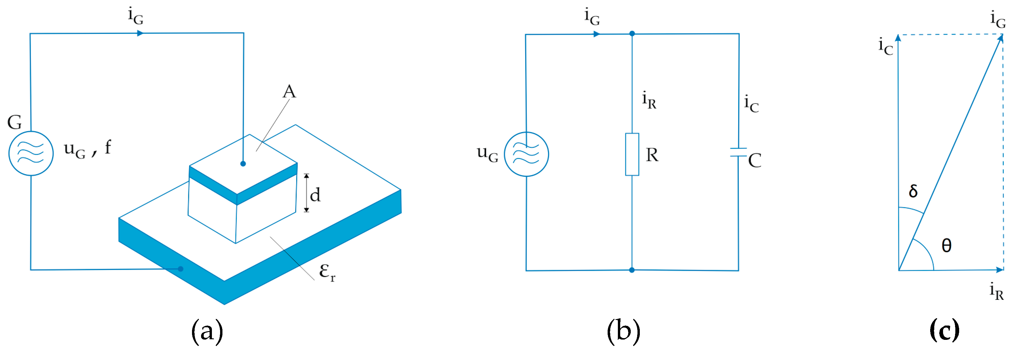
High frequency welding of polymer materials is performed using a high frequency alternating electromagnetic field in which the material to be welded is located and in which heat is generated under the effect of the field. The material to be welded is positioned between the upper movable electrode and the lower plate, which represents the immovable electrode. The electrodes are made of metal (aluminium or brass) and generally represent a capacitor having an upper plate (upper movable electrode), a lower plate (immovable electrode, work table) and a dielectric between the surfaces (material to be welded).
Figure 1 (a) shows the circuit of the capacitor with the upper plate of area A (upper movable electrode), the material to be welded with relative dielectric constant ε
r, and the lower plate (lower electrode or work table WT). On the plates of such formed capacitor a high frequency generator of alternating current G is connected,
Figure 1 (a), with a frequency f of usually 27.12 MHz. The voltage u
g of the generator is relatively high, usually about 800 to 2,000 V, at which a current i
g flows through the capacitor, reaching values between 0.2 and 0.6 A in practise. The power of the HF generator, which is used in clothing technology, reaches values up to 800 W when used for shorter welded joints on thinner materials (e.g., raincoats), and can be increased to values of 4 kW for longer and durable welded joints on thicker materials (tarpaulins, sunshades).
Any real capacitor can be represented as an equivalent or substitute scheme circuit consisting of a parallel connection of the resistor R through which the current i
R flows and an ideal capacitor through which the current ic flows,
Figure 1 (b).
From the technological point of view, it is interesting and significant that the electric power converted into heat is manifested as power dissipation at a resistor R,
Figure 1 (b), during the time of influence of the high frequency alternating field, and its value is the same:
where:
P – electric power [W]
uG – generator voltage [V]
iR – current which flows through the resistor [A]
Using the phase diagram, the current flowing through the resistor doing the work can be calculated using the equation:
where:
iR – current which flows through the resistor [Ω]
iG – current which flows through the generator [A]
θ – displacement phase angle [rad]
so, the power of alternating current is calculated from the equation:
From the
Figure 1 (c) it can also be seen that:
Inserting the expression (4) into expression (3) is gives:
From the
Figure 1 (c) it can also be seen that:
Inserting expression (6) into expression (5) gives:
By knowing that:
expression (7) can be written as:
Spurious resistance of the capacitor X
c is equal to:
where:
XC - spurious resistance of the capacitor [Ω]
ω – angular frequency [Hz]
C- capacity [F]
f – frequency [Hz]
Determining the current flowing through the capacitor, can be written as:
Inserting the expression (10) into expression (8) gives:
During the high frequency welding the upper electrode of area A which welds the polymer material of thickness d and relative dielectric constant ε
r together with the lower electrode form the capacitor with capacitance:
so, by inserting expression (12) into the expression (11), it is obtained the expression for the calculation of the generator power P from its voltage, i.e., the voltage of the upper electrode:
In practise, it is better to use an expression based on generator current rather than generator voltage, since this can be measured and adjusted. Thus, if the generator voltage is expressed as:
inserting the expression (14) into expression (13) gives:
Furthermore, inserting expression (12) into expression (15), gives the expression for calculating the generator power P via the anode current of the generator, i.e., the current of the upper electrode:
To achieve heating of the weld from room temperature T
1 to the melting temperature of the polymer material T
2, it is necessary to supply specific heat:
where:
QH - specific heat to warm up the material from room temperature to the melting temperature [J],
c - specific warm up heat of the polymer [J/kg°C]
m - mass of the material to be welded under the upper electrode [kg]
T2 – melting temperature of the polymer material [°C]
T1 – room temperature [°C]
The mass of the material to be welded can be expressed as follows:
where:
m – mass of the material to be welded [kg]
ρ – specific density of the material [kg/m3]
V – volume of the material [m3]
As the volume of the welded joint is equal to:
where:
V – volume of the welded joint [m3]
A – area of the material [m2]
d – thickness of the material [m]
by inserting the expression (19) into expression (18) the mass can be determined with expression:
Furthermore, inserting expression (20) into expression (17) gives:
In the same way, the expression for latent heat or heat of melting must be defined for the polymer material to be welded:
where:
QL – melting heat of the material [J]
m – mass of the material to be welded [kg]
L – specific latent heat to melt the material [J/kg]
Inserting expression (20) into expression (22) gives:
The total heat Q
T required to weld the polymer material is expressed as:
Inserting expression (21) and expression (23) into expression (24) gives:
that is:
As Q
T = P∙t, where t is time of the HF energy influence on the welded joint and P is the power of that field, it follows:
Inserting expression (26) and (13) into the expression (27), we get an expression for the necessary time of the HF energy influence on the welded joint, expressed as the work of the HF generator.
Total heat Q
T, required for welding polymeric materials, can be calculated with expression (25), and the power of the influence of the high frequency energy on the welded joint with expression (14). Thus, inserting the expression (13) and (26) into (27), it is obtained the expression for the required time of the high- frequency energy influence on the welded joint, expressed by the voltage of the high- frequency generator:
In the same manner inserting expression (26) and (16) into (27), it is obtained the expression for the required time of the influence of the high frequency power on the polymer joint expressed by the anode current:
Expression (29) can be used to calculate the required time of exposure of the high frequency generator, if the welding current is specified, which is measured with an amperemeter in the cathode circuit, since it is considered technically easier to achieve and relatively harmful (in contrast to the anode voltages, which can reach voltages up to several kV). In the same way, the most important technological parameter, the time t, is determined, which is required for the influence of the high frequency energy on the welded joint, when all known relevant parameters for welding polymer materials are known:
ρ - specific density of the polymer material to be welded [kg/m3],
d – thickness of the polymer material to be welded, [m],
QH - specific heat to warm the material from room temperature to the melting temperature [J],
c - heat of the polymer material to be welded [J/kgm],
T2 – softening temperature of the polymer material to be welded [°C],
T1 – initial temperature of the polymer material to be welded [°C],
QL – heat to melt the polymer material [J],
L – specific latent heat of the polymer material to be welded [J/kg],
QT - total necessary heat to weld the polymer materials [J],
f – frequency of the HF generator [Hz],
uG – generator voltage [V],
iG – generator anode current [A],
P – generator power [W],
εr – relative dielectric constant of the polymer material to be welded,
A – area of the upper electrode [m2],
tgδ – dielectric loss angle of the polymer material to be welded and
t – welding time of the HF joint [s]
All the above parameters are known or can be measured before the technological process of welding the polymer materials, and the required welding time can be specified in advance using expression (29). After that, by fine-tuning only two parameters, the welding time t, and the anode current ig, the welded joint with the desired properties can be set (visual appearance and strength of the weld).
Considering the previously listed key parameters of high frequency welding used in the mathematical derivation, it can be concluded that these are also most of the parameters on which the HF technique of welding depends. In addition to the above parameters, we can also mention the area and shape of the electrode, the pressure force of the upper electrode, the maximum power of the HF generator and the time required for cooling the sample after welding.
