1. Introduction
Ultralight power generation equipment and systems have many similarities and differences compared with aviation power generation systems, Marine integrated power systems, and electric vehicle power systems. One or more prime movers provide several power generation scenarios. According to the topology of the power generation system, the generator output power can be subdivided into series type, parallel type, and hybrid type, and according to the source of energy, it can be divided into all-electric and hybrid. The single power and weight of ultra-light mobile power generation equipment is minimal (usually not more than 1 kW, 10 kg), and the speed is relatively high (rated speed is not less than 6500 rpm), which is different from the two-stroke aero-engine and megawatt high-power diesel engine in the power system of electric transmission vehicles. This kind of ultra-light power generation equipment system is suitable for micro-displacement four-stroke gasoline engines, which have specific compact requirements, and higher speed can reduce the size and weight burden of generator design. In light mobile power generation equipment, the generator in the power unit usually uses a permanent magnet generator. Due to the size and efficiency limitations, it is difficult to use the generator with electric excitation or compound excitation, which also increases the difficulty of the internal speed regulation and control of the power unit. In addition, ultra-light mobile power generation equipment has different system characteristics and requirements, such as no energy storage unit, lightweight, high speed, low power and small inertia, scalability, and other application characteristics. It should be noted that to ensure the reliability of use, the ultra-light power generation equipment system does not contain lithium batteries, supercapacitors, or other energy storage modules.
The speed regulation of the power generation unit (composed of an engine and a generator) relies on the engine to control the speed, and the generator regulates the electromagnetic torque (engine load torque) through the rear rectifier unit and then controls the output power of the unit [
1,
2,
3,
4,
5,
6]. This method can make the unit respond quickly to the load power demand and is widely used in general power plants, hybrid vehicle systems, and Marine integrated power systems [
7]. The generator sets in these power environments do not require frequent speed regulation, and the prime mover can be selected with sufficiently large specifications [
8]. The researchers found that for the generator sets that make up the vehicle's integrated power system: On the one hand, due to the efficiency of the installed capacity in the car, the power of the engine and the generator is roughly similar when the vehicle needs high-speed bending or rapid acceleration, the sudden increase in the load power of the vehicle may make the electromagnetic torque of the generator as a resistance moment exceed the engine output torque in a short time, and the connecting shaft of the power generation unit is mainly affected by the generator, resulting in the instability of the unit; On the other hand, due to the coupling relationship between the output capacity of the unit and the fuel economy and the speed, the unit needs to switch to different target speed points frequently according to the driving demand [
9,
10,
11,
12]. In response to the above problems, scholars have proposed control strategies such as constant speed QFT robust control, fuzzy control, and sliding mode control [
13,
14,
15,
16]. However, due to the characteristics of the ultra-light power station system, such as small inertia, small capacity, high rated speed of the power generation unit, and unbuffered energy storage unit, the above strategies are not applicable. Therefore, it is necessary to design a speed stability control strategy for its power generation unit to maintain lasting and stable operation under different working conditions and switching conditions.
The series hybrid power system has the advantages of a simple structure and relatively simple optimization control. No mechanical connection can be set between the engine and the transmission, and the engine speed and torque can be adjusted to make it work in the maximum efficiency zone. In recent years, the problem of coordination control of engine-generator sets used in many independent power systems' primary power sources at home and abroad has become increasingly prominent [
13]. During the running of hybrid electric vehicles, the engine needs to switch the speed operating point according to the optimal fuel economy consumption following the control strategy. However, an excessive loading rate will limit the speed adjustment ability of the engine generator set. Currently, the actual speed can no longer track the target speed, and the required power of the rear power chain exceeds the output capacity of the engine generator set. Because of this problem, literature [
17] studies the influence of different loading rates on the engine speed-switching process. It gives the maximum allowable loading rates at different speeds through simulation to avoid engine overload. Wen Boxuan et al. [
7] improved the speed adjustment ability by setting the transmission device between the engine and the generator. However, the limiting loading rate is too low. In that case, it will slow down the power response ability of the unit, and if the limiting loading rate is too large, it is difficult to avoid the oscillation of the unit speed. Obtaining the optimal limiting amplitude of the loading rate takes work. Because of the cancellation of the mechanical connection between the unit and the motor, the generator is generally dragged directly by the engine, and increasing the transmission device is more suitable for parallel and hybrid systems. In short, there is little research on this problem and no unified solution. In the dynamic regulation of the unit, the internal problem of the engine-generator set system is mainly speed adjustment [
18], and the external problem is mainly the electric power response output to the bus [
19,
20,
21]. Based on these two problems, this paper adopts the speed regulation method of the engine throttle opening to adjust the output power and the generator controller to adjust the speed to control the changes of electromagnetic torque reasonably and avoid the situation of engine overload or even car failure during the dynamic regulation process. At the same time, the adjustment time and the minimum energy loss of the whole process are optimized, and the high-quality power supply to the DC bus is realized by rationally configuring the electromagnetic torque variation interval of the generator. Through the hardware-in-the-loop simulation of a series-connected vehicle-mounted integrated power system, the reliability of the proposed control strategy is verified.
Because of its simple structure and flexible layout, a series power generation system has become one of the typical schemes of power generation equipment. The engine-generator set is used for external power supply. However, because the stability of a single chain structure could be more substantial, a reasonable design is needed to achieve coordinated and efficient work of the system [
2,
3,
4,
5]. When the load power is suddenly increased, or the long-term high-power operation and other extreme conditions, the following characteristics of the power supply system are required. Especially in the rapid acceleration process, the dynamic change of load power is excellent, so it is urgent to research power balance control strategy. Gasoline engine has the characteristics of nonlinear and multi-operating conditions, and their dynamic characteristics change with the change in speed and load. At present, some scholars have studied the control of gasoline engines. In literature [
2,
3], sliding mode control and synthesis methods were used to study the speed control of automobile gasoline engines. In contrast, in literature [
4,
5], QFT robust control and dynamic output feedback control was used to study the constant speed control of small unmanned helicopter engines. In the above control methods, most of the engine system is regarded as a single class of uncertain or parameter perturbation system, without considering the different dynamic performance of the engine under different working conditions, and the dynamic performance of the system is not improved from the Angle of load disturbance feedforward compensation.
This paper analyzes the working mechanism of a small gasoline generator. It is concluded that the main factor that destroys the steady state of the system is the sudden change in the system load. Therefore, a feedforward multimodal feedback control algorithm is proposed, combining feedforward control, traditional PID, and fuzzy control. This method uses fuzzy control when the operating condition changes, linear PID control when the system is steady, and feedforward compensation to suppress the load disturbance. The simulation and test results show that this method effectively improves the steady-state and dynamic performance of small gasoline generators.
5. Simulation and Experimental Results
5.1. Engine control strategy simulation and experimental analysis
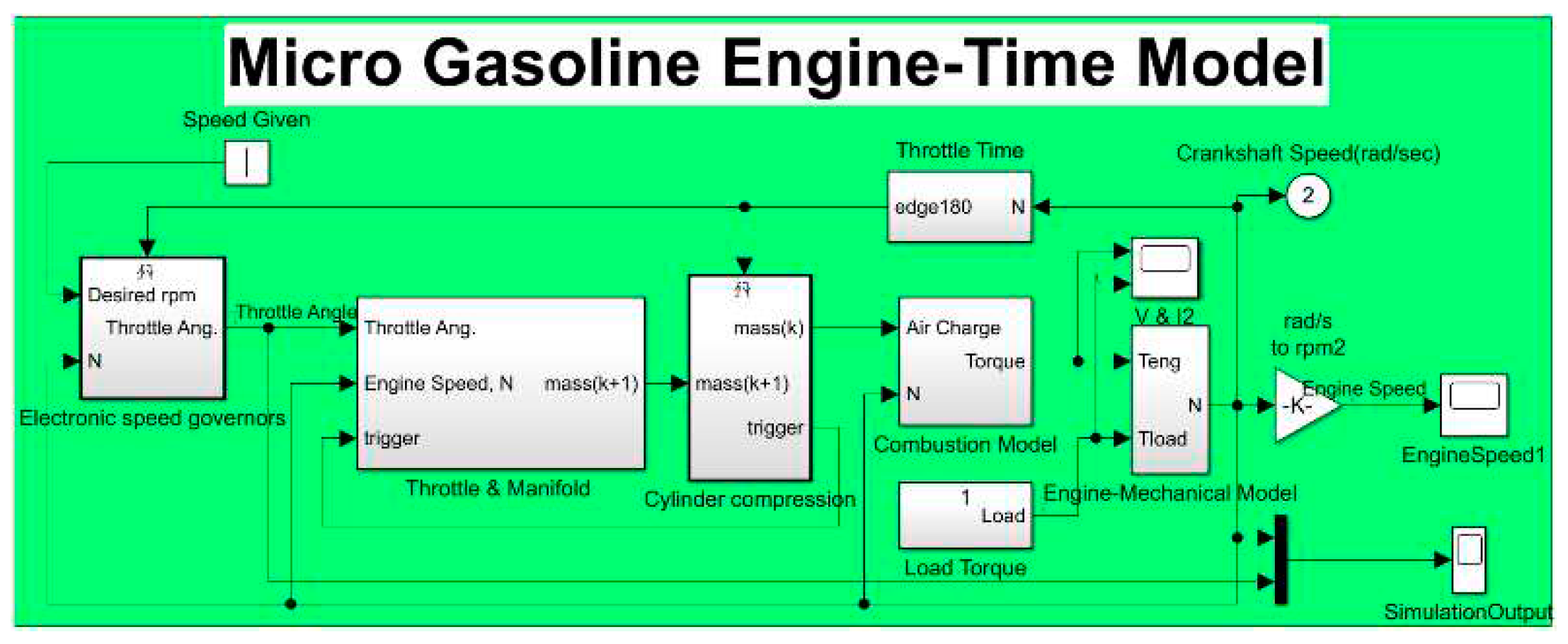
MATLAB/Simulink tool was used to establish the models of feedforward feedback closed-loop control system of a four-stroke gasoline engine, as shown in
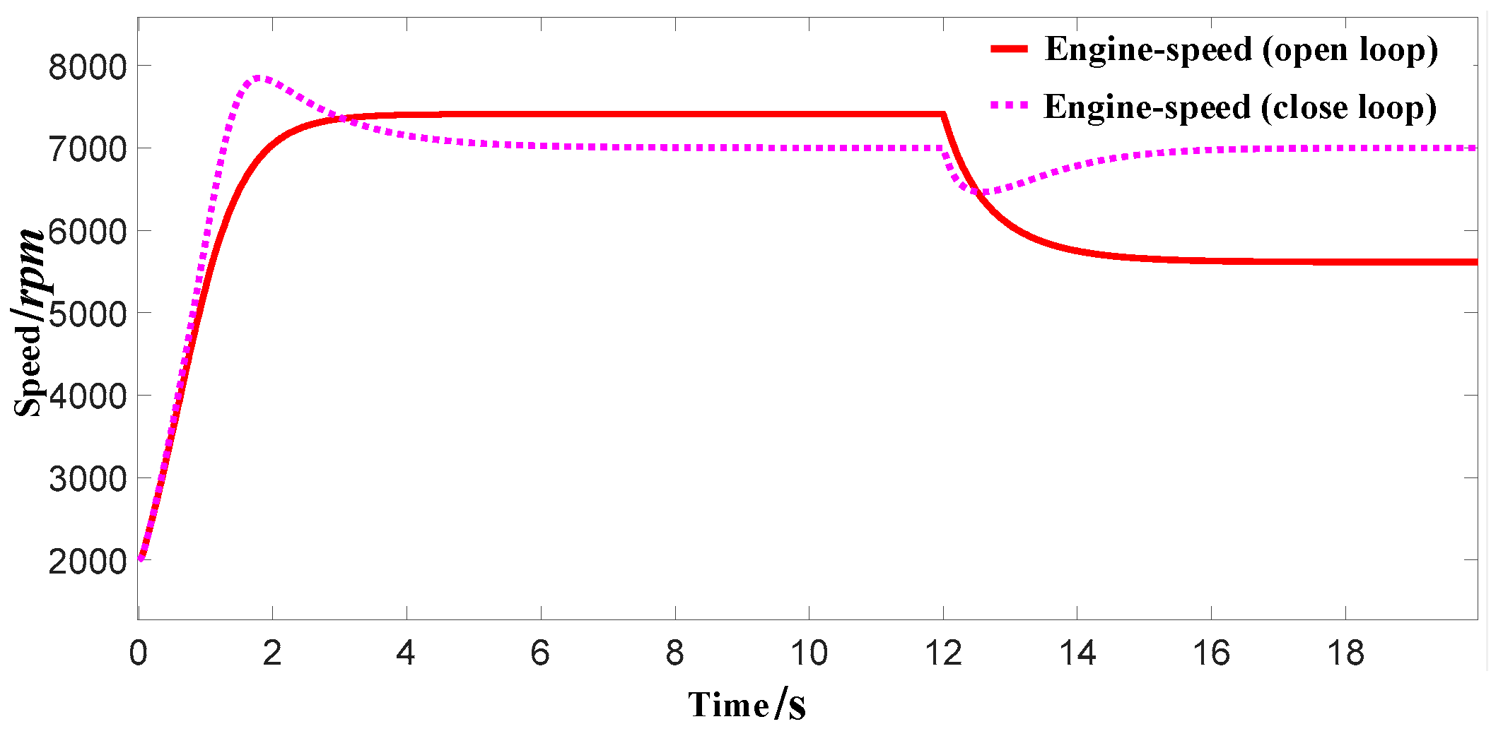
Figure 14. To start the simulation process, it is necessary to assign the initial speed N0 of the power unit and the target speed Ng (2000 rpm, 7000 rpm), the initial carburetor opening θ(15°) and set the load mutation rule (12s mutation), and the load carried by the generator is equivalent to the electromagnetic torque (0.75 Nm).
The simulation results show that when the load current feedforward compound speed feedback control loop is adopted, the speed overthrow is less than 12% during the load switching process, and the rated speed can still be maintained at 7000rpm without shock under 100% heavy load mutation condition, and the operation is stable. Compared with the conventional feedback control, the performance in all aspects has been greatly improved.
Figure 15.
Open-loop and closed-loop engine speed response.
Figure 15.
Open-loop and closed-loop engine speed response.
Figure 16.
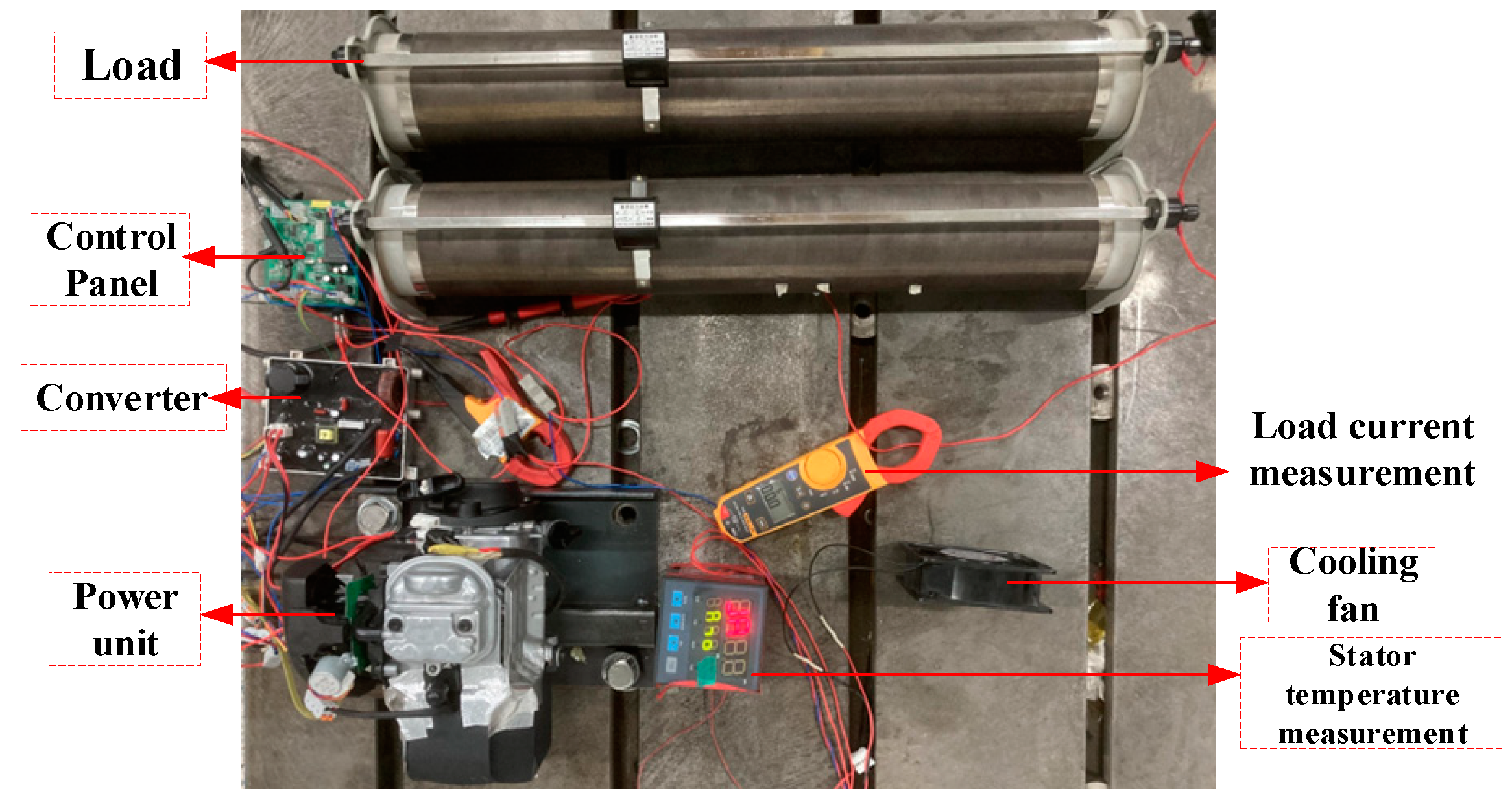
Generator set experiment platform.
Figure 16.
Generator set experiment platform.
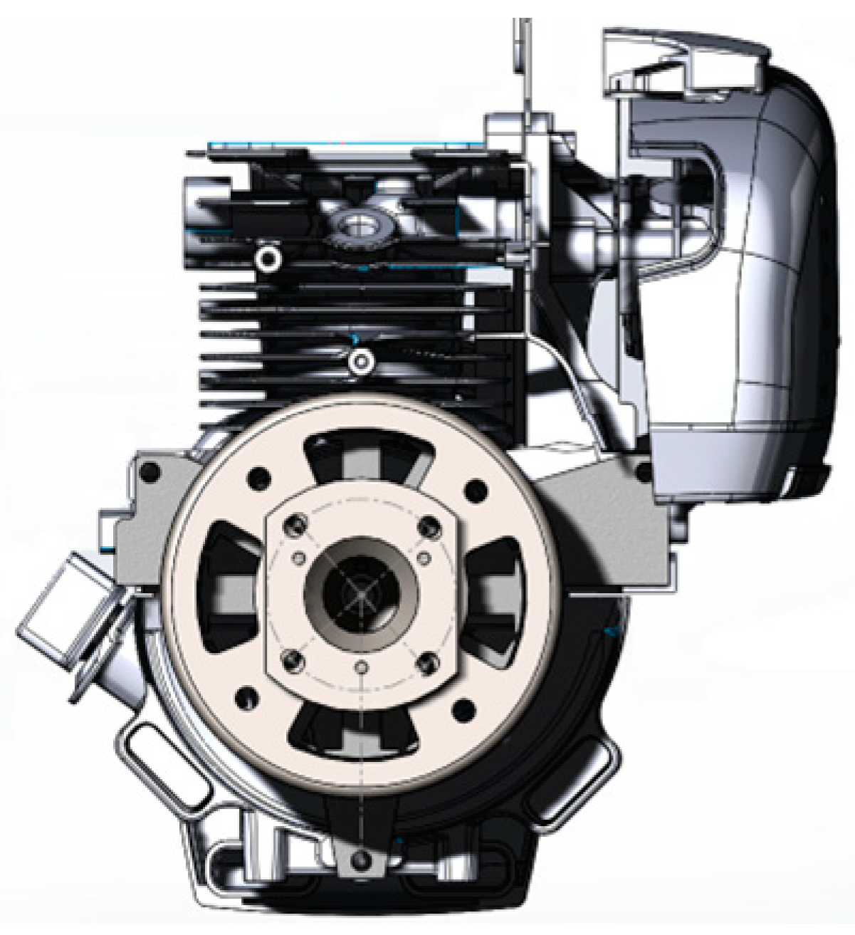
In order to verify the practicability of the algorithm, a machine matching experiment is carried out in the laboratory. The prototype used in the test was redesigned from a single-cylinder, air-cooled, four-stroke small gasoline engine produced by a machinery company. Removing the engine flywheel clutch parts and magneto modules, the cylinder diameter × stroke is 40 mm×30 mm, the compression ratio is 8.5:1, the rated output power is 0.85 kW(7000 rpm), and a lot of tests have been carried out.
Figure 17.
Overall diagram of generating unit (engine-generator).
Figure 17.
Overall diagram of generating unit (engine-generator).
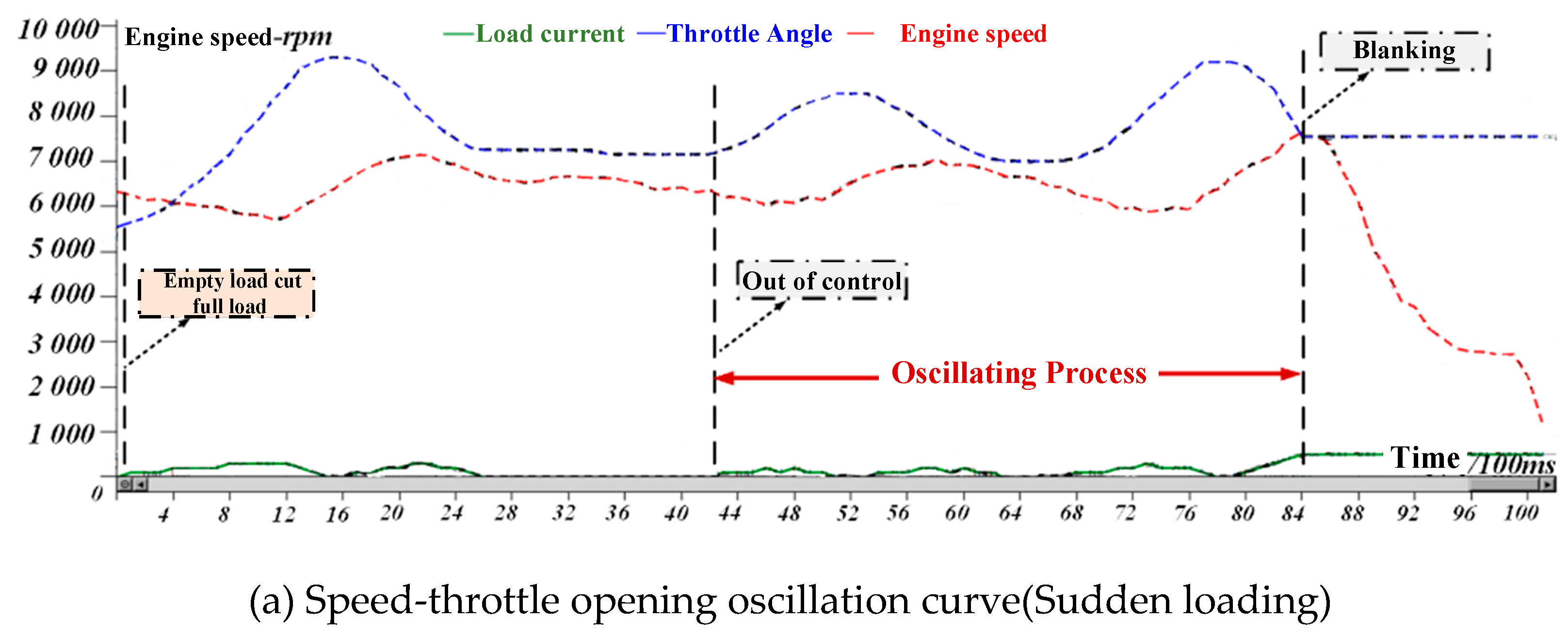
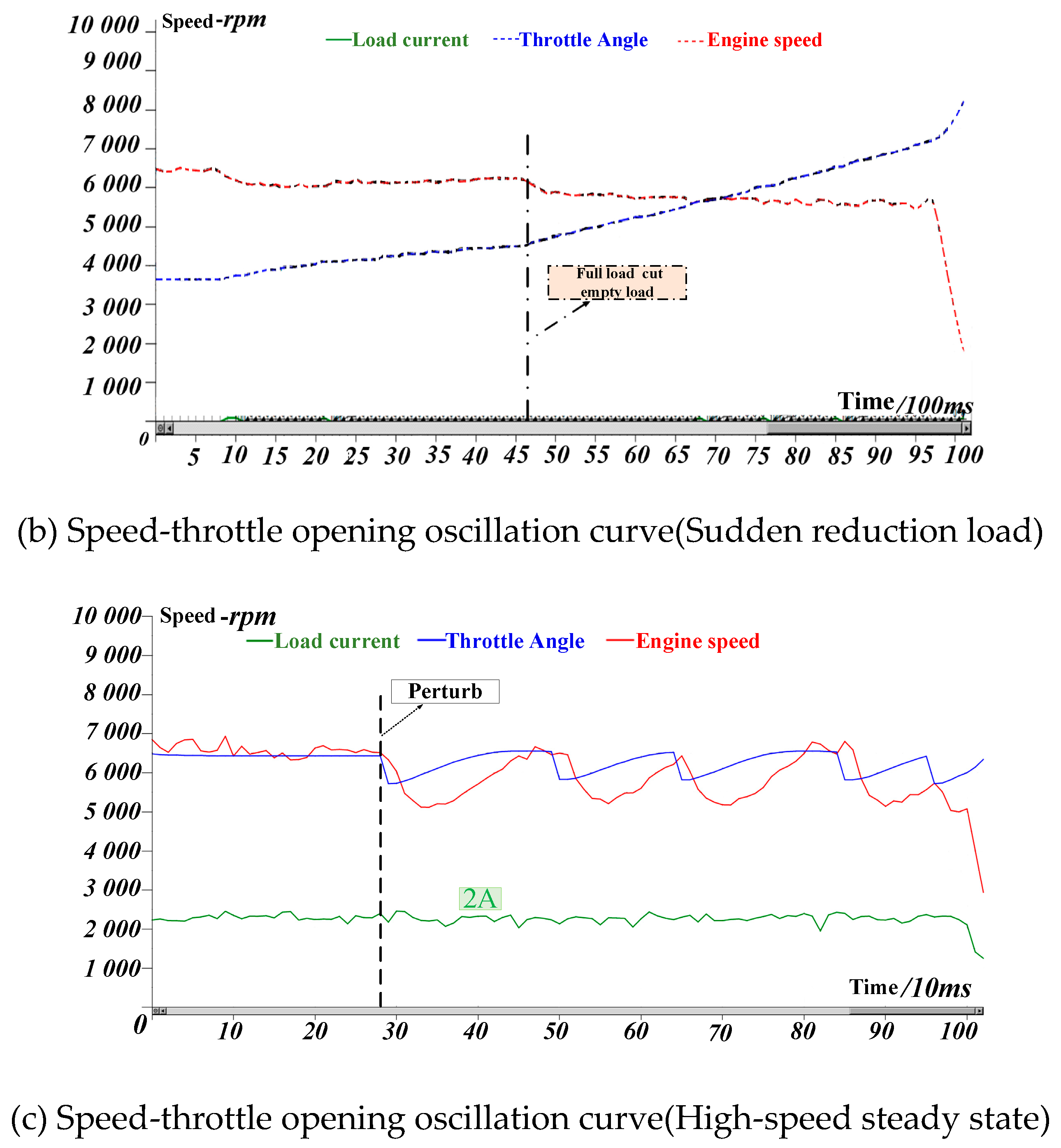
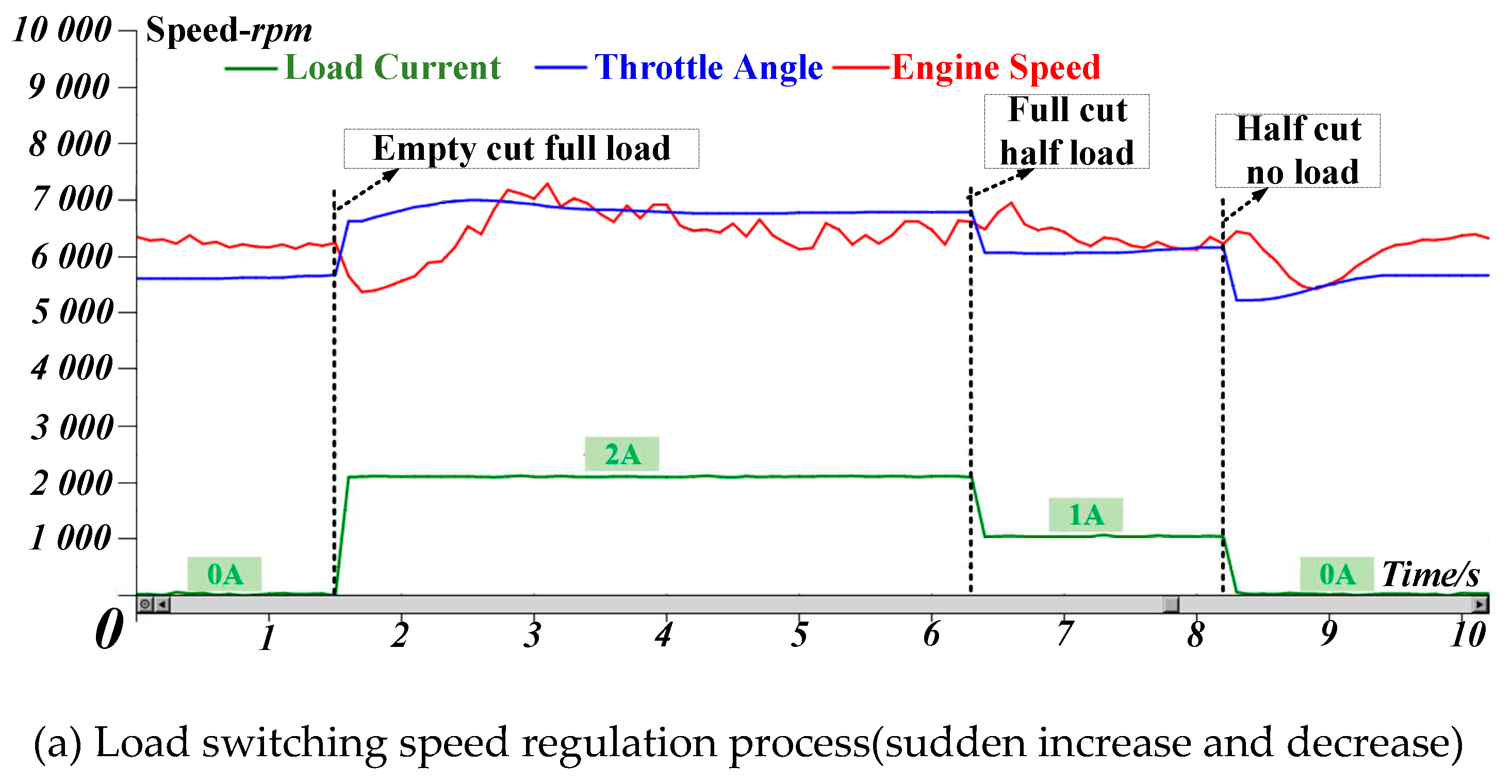
Figure 18a is the speed fluctuation curve when the load is abruptly applied, and
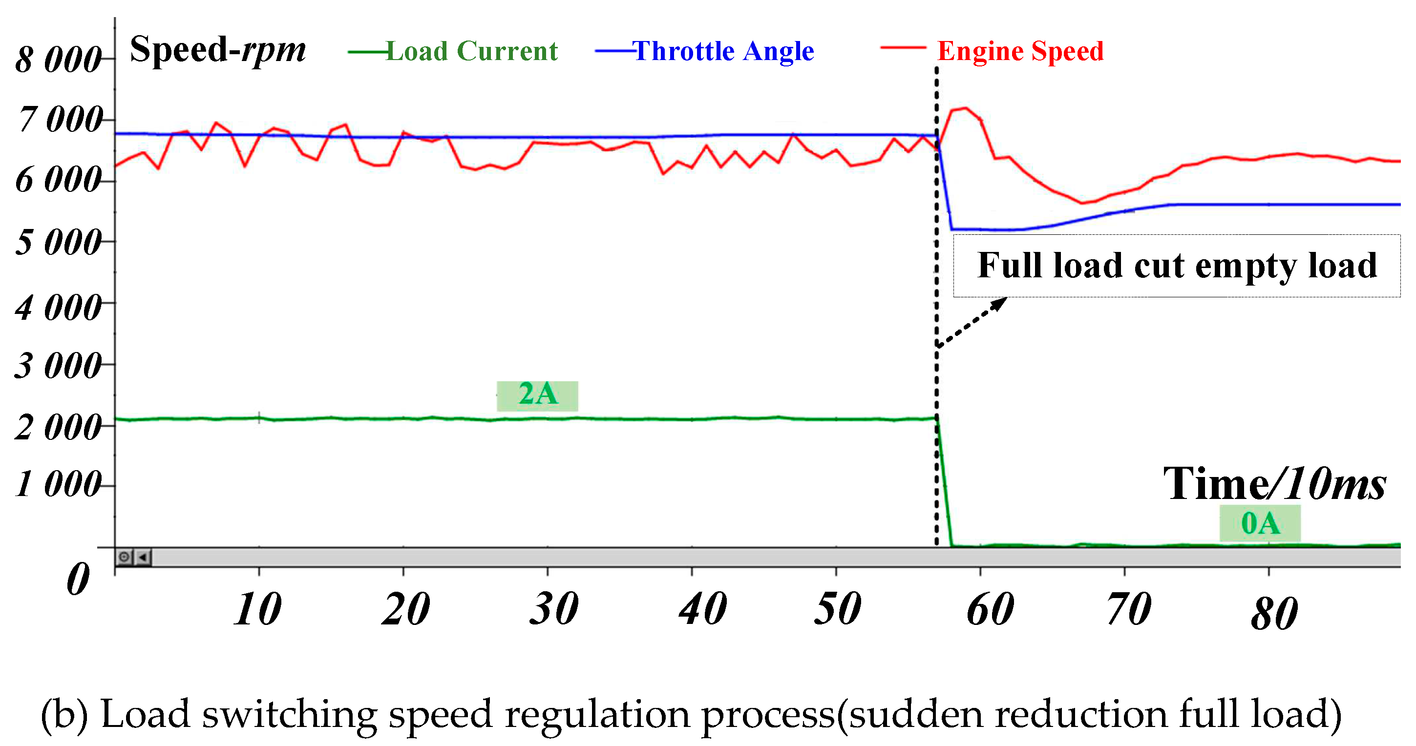
Figure 18b is the speed fluctuation curve when the load is abruptly reduced.
Table 3 shows the analysis of load current and carburetor opening test data related to steady state test and transient test. It can be seen that under the condition of sudden load change, it has a fast speed stabilization ability. In particular, a full load full cut or full throw achieved a response recovery within 0.9 seconds.
5.2. Simulation analysis of generator control strategy
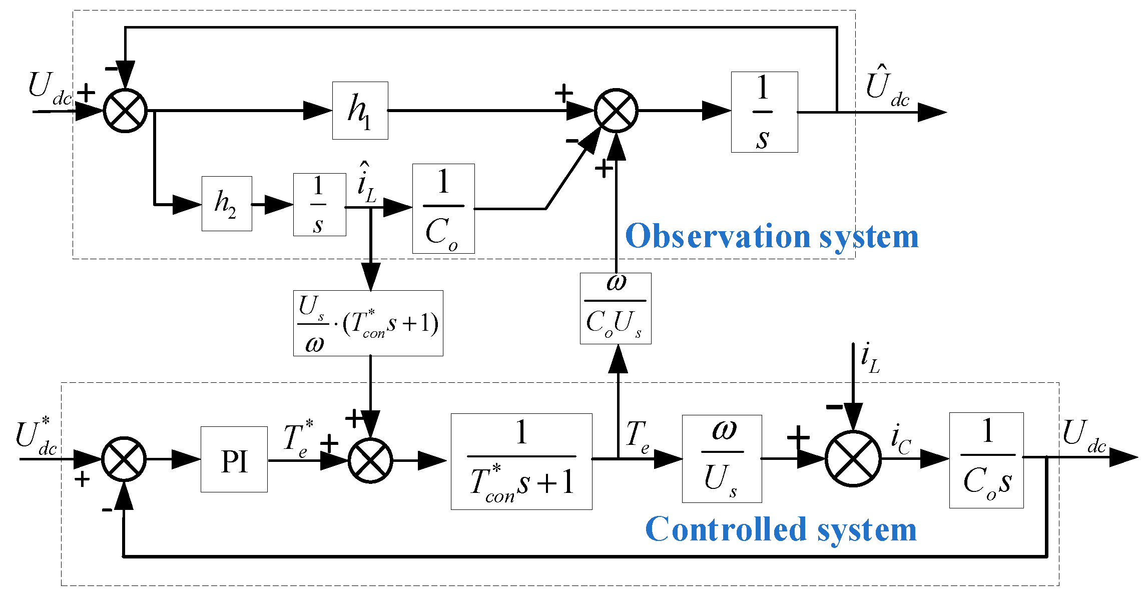
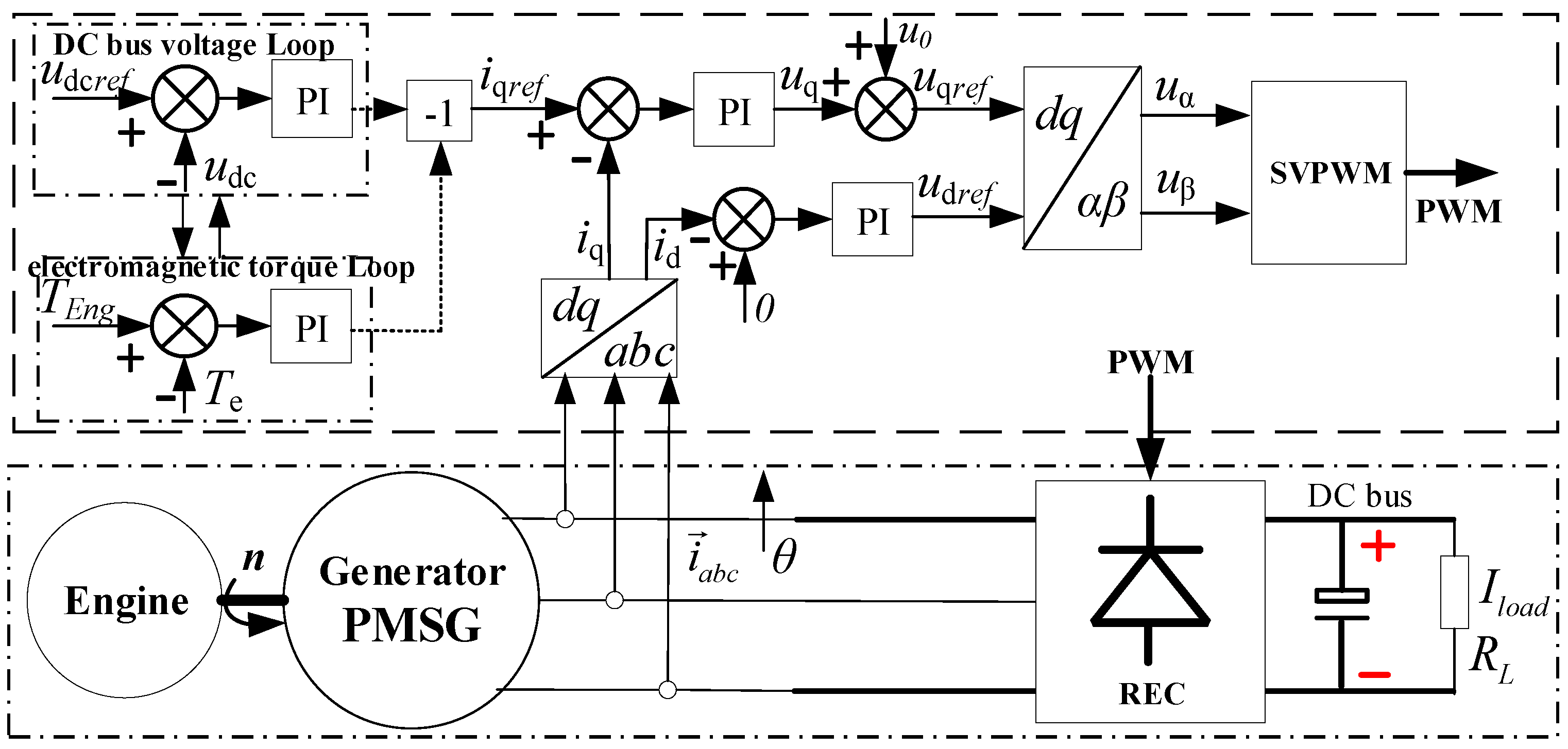
In order to verify the performance and effectiveness of the load torque observer and the designed generator control strategy, MATLAB/Simulink platform was used to build a simulation model for simulation verification. Generator simulation parameters are shown in
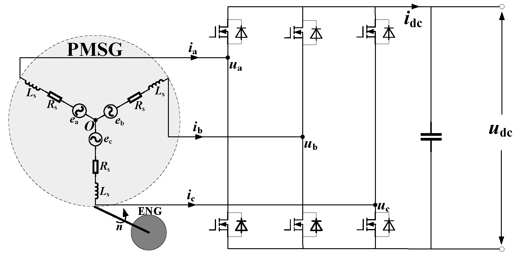
Table 3. According to the topology shown in
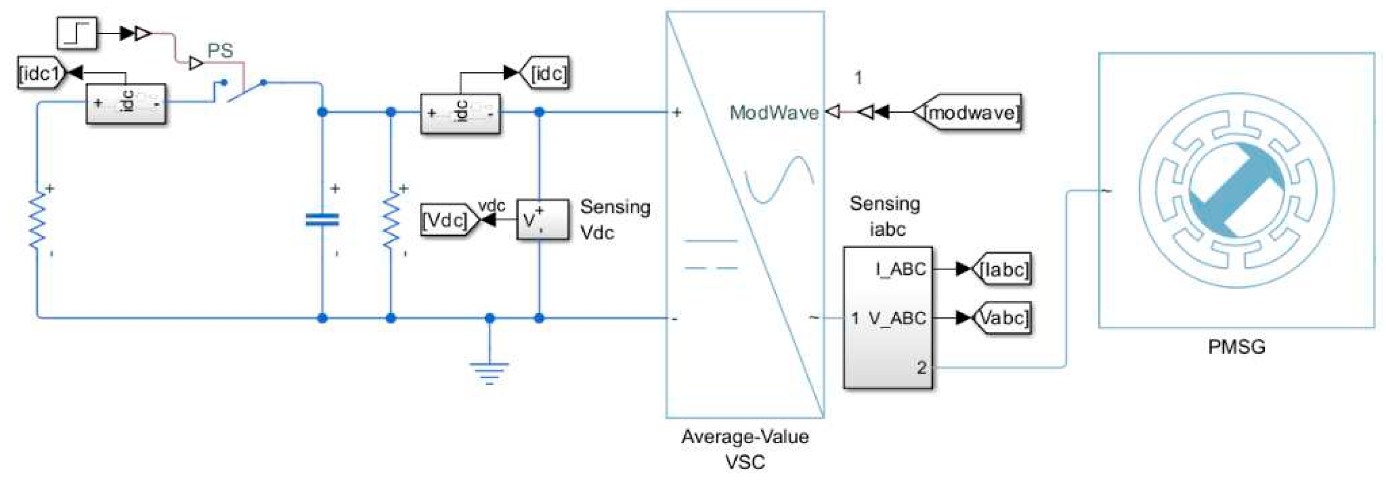
Figure 1 and the proposed control strategy, the inverter AC output of the whole power generation system is simulated. The Sinmulink simulation diagram is shown in
Figure 19.
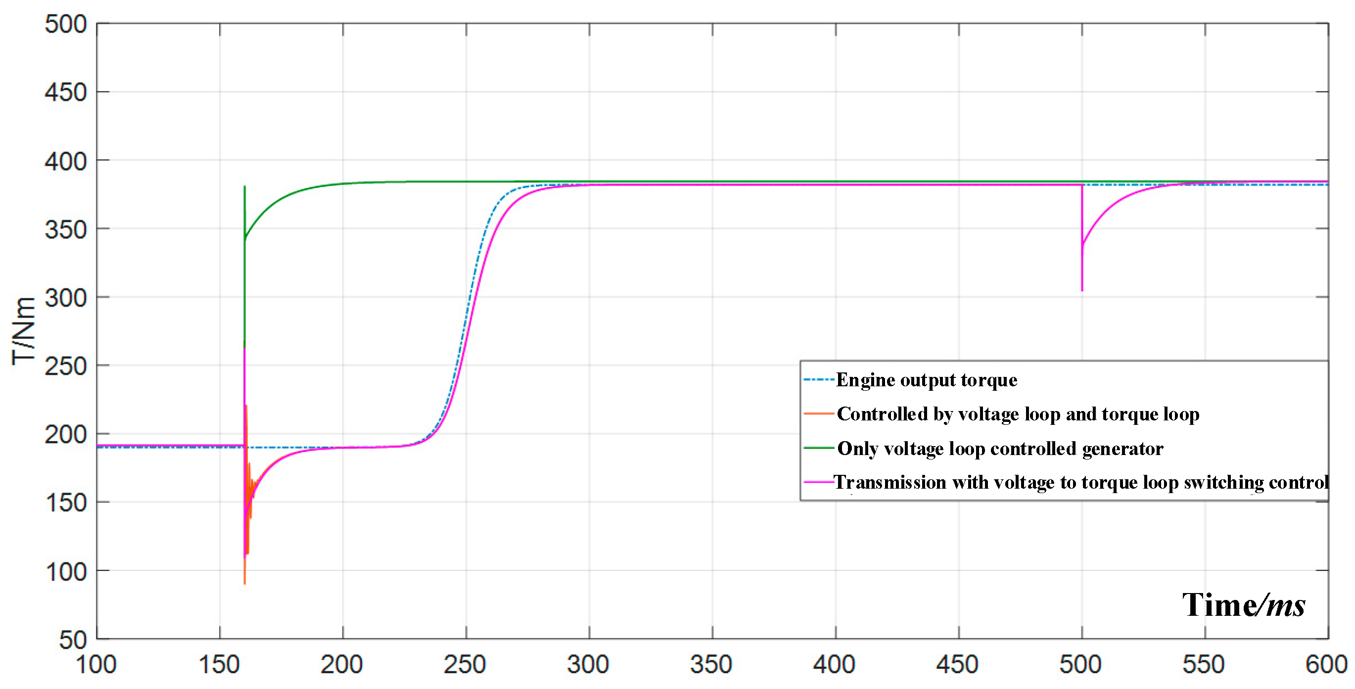
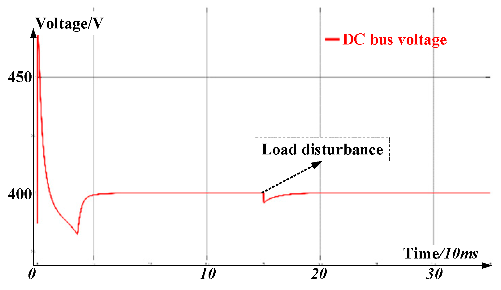
As can be seen from the figure, when the load is suddenly discharged and suddenly loaded, the load torque feedforward compensation is added, and the voltage fluctuation is reduced by an average of 12V (full load fluctuation) compared with that when the traditional PI speed controller is used. In particular, considering the transient process of sudden load change, the following of the generator electromagnetic torque to the engine output torque is greatly improved, the introduction of torque loop alleviates the torque imbalance between the generator and the engine, and the introduction of feedforward term further alleviates the imbalance problem, where the degree of direct imbalance between the generator and the engine is represented by the instability parameter S. Relevant simulation waveforms are shown below. The simulation results show that the load torque feedforward compensation and torque loop switching control shorten the time for the system to recover to the stable state after the disturbance, and improve the anti-load disturbance ability of the system.
Figure 20.
Comparison of electromagnetic torque waveform under different control strategies (Torque×500).
Figure 20.
Comparison of electromagnetic torque waveform under different control strategies (Torque×500).
Figure 21.
DC-bus Voltage waveform of system (under optimization strategy).
Figure 21.
DC-bus Voltage waveform of system (under optimization strategy).
5.3. Experimental analysis of inverter control strategy
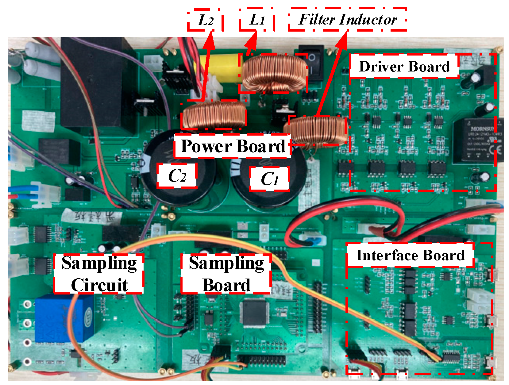
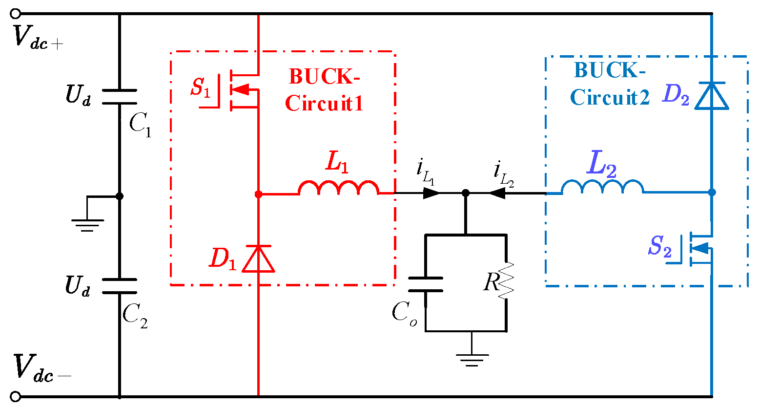
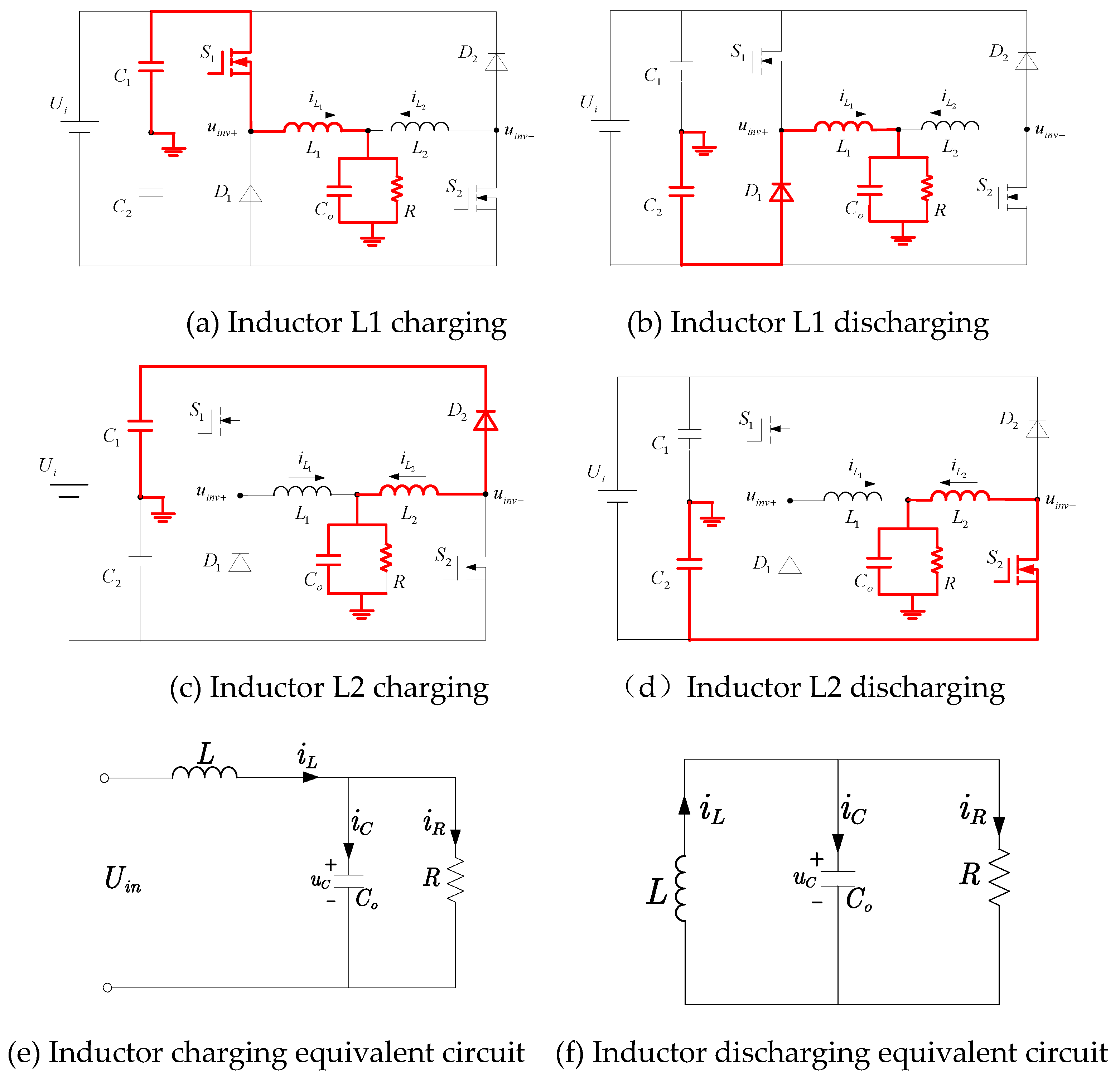
An inverter experiment platform based on STM controller was built to verify the proposed inverter control strategy. The inverter platform, as shown in the figure below, includes the main circuit of the Dual Buck topology inverter and the circuit parts related to the control and communication modules.
Figure 22.
Dual buck inverter main circuit and controller diagram.
Figure 22.
Dual buck inverter main circuit and controller diagram.
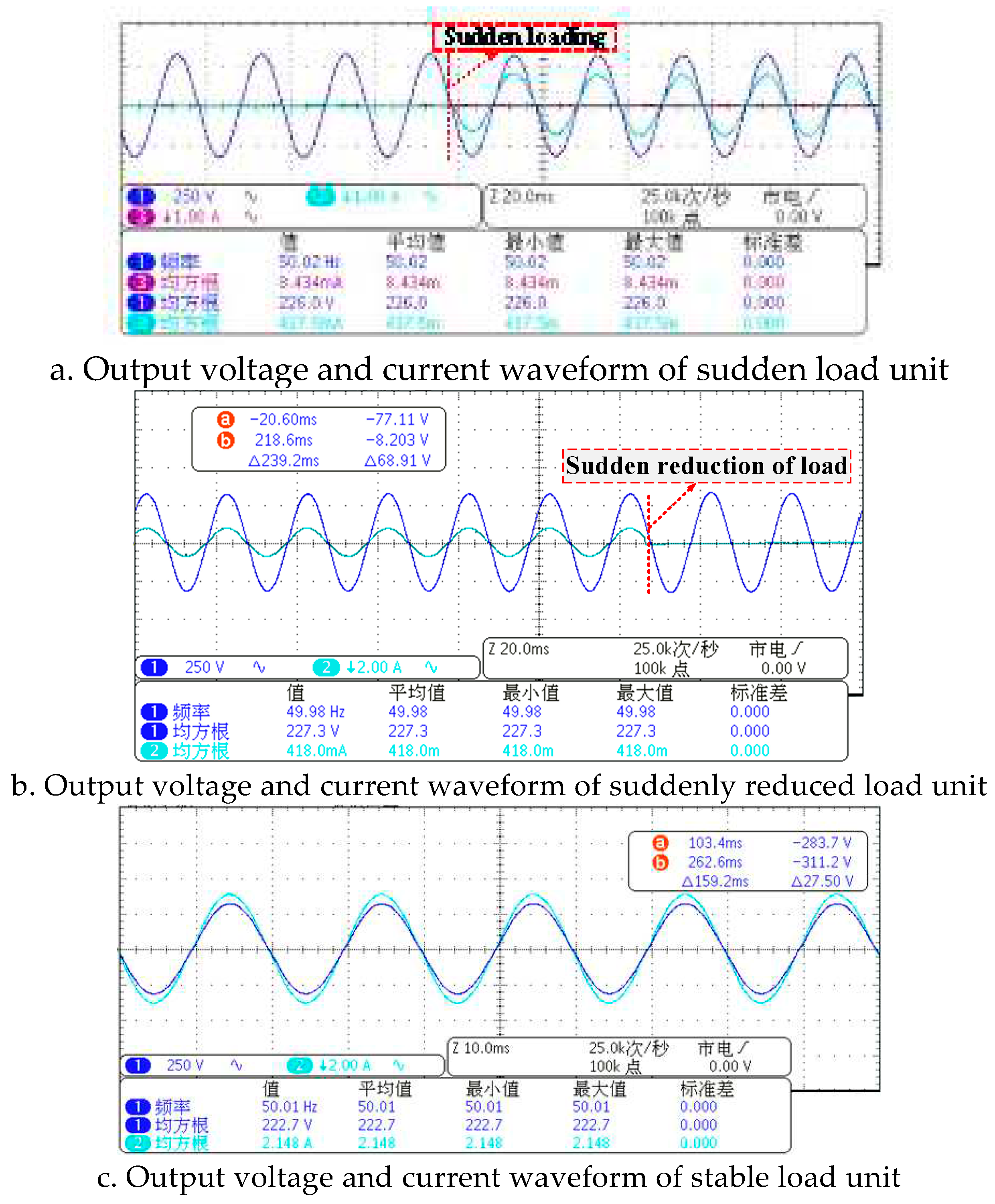
The experimental waveform results are as follows. Whether it is sudden load or sudden load reduction, or even considering 100% load change, the inverter can always restore the normal waveform output within 5ms, and the transient process of 5ms can be ignored, the overall voltage waveform quality is high, and the average THD is within 0.7%.
Figure 23.
Actual output waveform of dual buck inverter.
Figure 23.
Actual output waveform of dual buck inverter.
