1. Introduction
In the process of producing, maintaining, and servicing concrete components, it is challenging to completely eliminate initial defects such as pores, voids, and micro-cracks due to various factors including production technology, maintenance conditions, and external environment [1-3]. As a result of applied loads and exposure to external environmental conditions, these microscopic defects within the component progressively expand and interconnect, leading to the formation of macroscopic cracks and, in severe cases, damage to the entire component.
Indeed, the cracking of the concrete protective layer represents only one form of structural crack. The presence and evolution of various types of cracks not only lead to stress redistribution within concrete structures but also alter the distribution of influencing factors, such as chloride ions and temperature, among others. These changes can significantly impact the corrosion of steel bars within the structure [
4,
5].
The shear failure of reinforced concrete beams typically constitutes a brittle failure, presenting a challenge in providing early warnings as there are minimal discernible signs prior to failure. The risk associated with shear failure is greater than that of bending failure due to the lack of obvious warnings before the occurrence of failure [
6,
7]. Moreover, the expansion and evolution of concrete cracks contribute to the deterioration of physical and mechanical properties of concrete members, including load-bearing capacity and deformation performance. Consequently, this degradation can impact the safety, applicability, and durability of the structure. Given these considerations, it becomes essential to thoroughly investigate the expansion of cracks during the failure process of reinforced concrete beams.
Rombach [
8] performed numerical and continuum media mechanics simulations of flexural shear crack extension in concrete beams without transverse reinforcement. The study involved numerical and continuum media mechanics simulations to investigate flexural shear crack extension in concrete beams without transverse reinforcement. The researchers utilized concrete damage plastic material modeling to develop the model, incorporating the crack extension method and the diffuse cracking method. By comparing the crack patterns observed in actual beam tests with the results obtained from different finite element models, the study aimed to gain insights into crack extension and internal force redistribution within concrete members. Crack width, interface roughness between cracks and concrete strength have an effect on the shear transfer capacity of the cracked interface [
9,
10]. Yang [
11] conducted an experimental study on the shear performance of continuous beams of lightweight aggregate concrete and fitted a discount factor for the shear capacity, which was related to the maximum aggregate particle size, density and splitting tensile strength of lightweight aggregate concrete.
Yin [
12] derived an expression for crack extension resistance in ordinary three-point bending concrete specimens and investigated the influence of the span-height ratio on the fracture process of three-point bending concrete beams. The findings indicate that the crack extension resistance curve exhibits an increase with crack extension, and both the curve and the fracture process zone curve are unaffected by the span-height ratio. However, they do demonstrate an increase with the specimen height
According to the development pattern, the surface cracks of reinforced concrete are mostly open type (type I, Opening mode) cracks: under the action of tensile stress orthogonal to the crack surface, the crack surface produces opening displacement (displacement is orthogonal to the crack surface), and the upper and lower displacement are opposite. Sliding Mode (type II, Sliding Mode) crack: under the shear stress parallel to the crack surface and perpendicular to the crack tip line, the crack surface produces relative slip (displacement parallel to the shear stress direction); Tear type (type III, Anti-plane Shear Mode) crack: under the shearing stress perpendicular to the crack surface and parallel to the crack tip line, the crack surface produces three kinds of relative slip (displacement parallel shear stress direction) along the crack surface. In the process of shear failure, the internal stress state of reinforced concrete beams is complicated, and the surface cracks are mostly Ⅰ-Ⅱ compound cracks. The expansion of opening type crack (type I) and sliding type crack (type II) is prone to low stress brittle fracture[
13], which accords with the characteristics of brittle materials such as concrete and rock.
By exploring the evolution law of damaged crack defects, it is hoped to describe their mechanical properties in essence. The direct way to solve this problem is to study the evolution law of damage fracture defects. However, it is difficult for classical fracture mechanics to describe the damage degree of concrete crack tip through the mesoscopic level[
14]. Therefore, by considering the mechanical characteristics of cracks and pores inside concrete as a damage field with coordinated deformation and continuous force, the development and evolution law of damage cracks inside concrete based on the above ideas can fully reflect the bearing capacity and failure characteristics of concrete materials[
15].
In order to accurately simulate the mechanical properties of reinforced concrete under reciprocating loads, a nonlinear finite element model of Abaqus was established based on the constitutive relation considering the cyclic loading characteristics of steel. In order to verify the reliability of the finite element analysis results in this paper, the finite element analysis results of simple supported beams are compared with the test results. The reciprocating loading modes of beam end controlled load and displacement-controlled load is proposed respectively, which can simulate the effects of horizontal earthquake, gravity load and axial pressure on reinforced concrete frame joints. The law of shear crack expansion of reinforced concrete frame joints in practical engineering is investigated systematically.
2. Comparison of Finite Element Model and Experiment Results
2.1. Overview of the Test
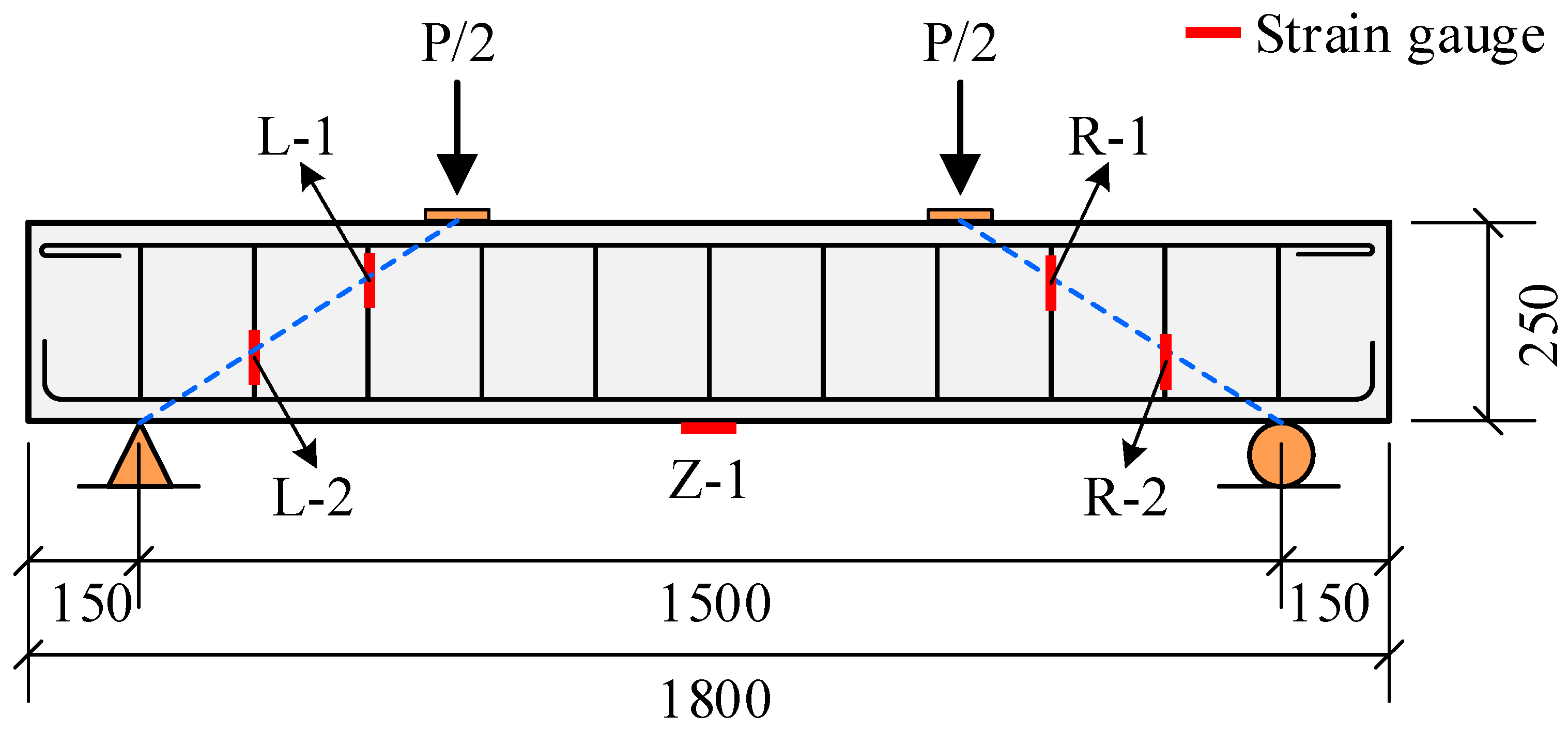
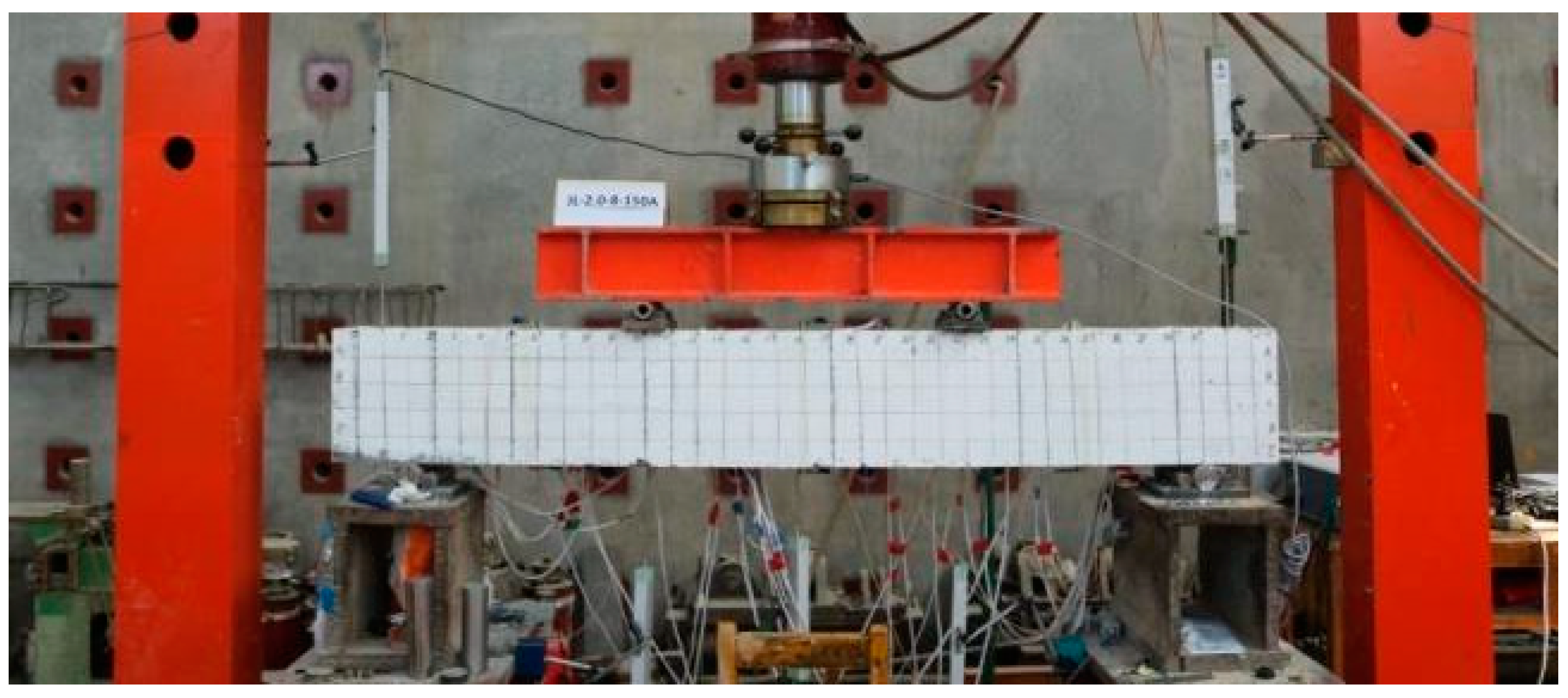
To validate the accuracy of the finite element modeling, an Abaqus model is created based on the experimental investigation of crack extension patterns in reinforced concrete simply supported beams, documented in literature[
16]. The test beams have cross-sectional dimensions of 150mm×250mm, a total length of 1800mm, and a calculated span of 1500mm. The pads used in the experiment have cross-sectional dimensions of 150mm×60mm×20mm. The reinforcement details are provided in
Table 1, and the dimensions and reinforcement arrangement of the test beams can be seen in Fig. 1 based on the results of the experimental study.
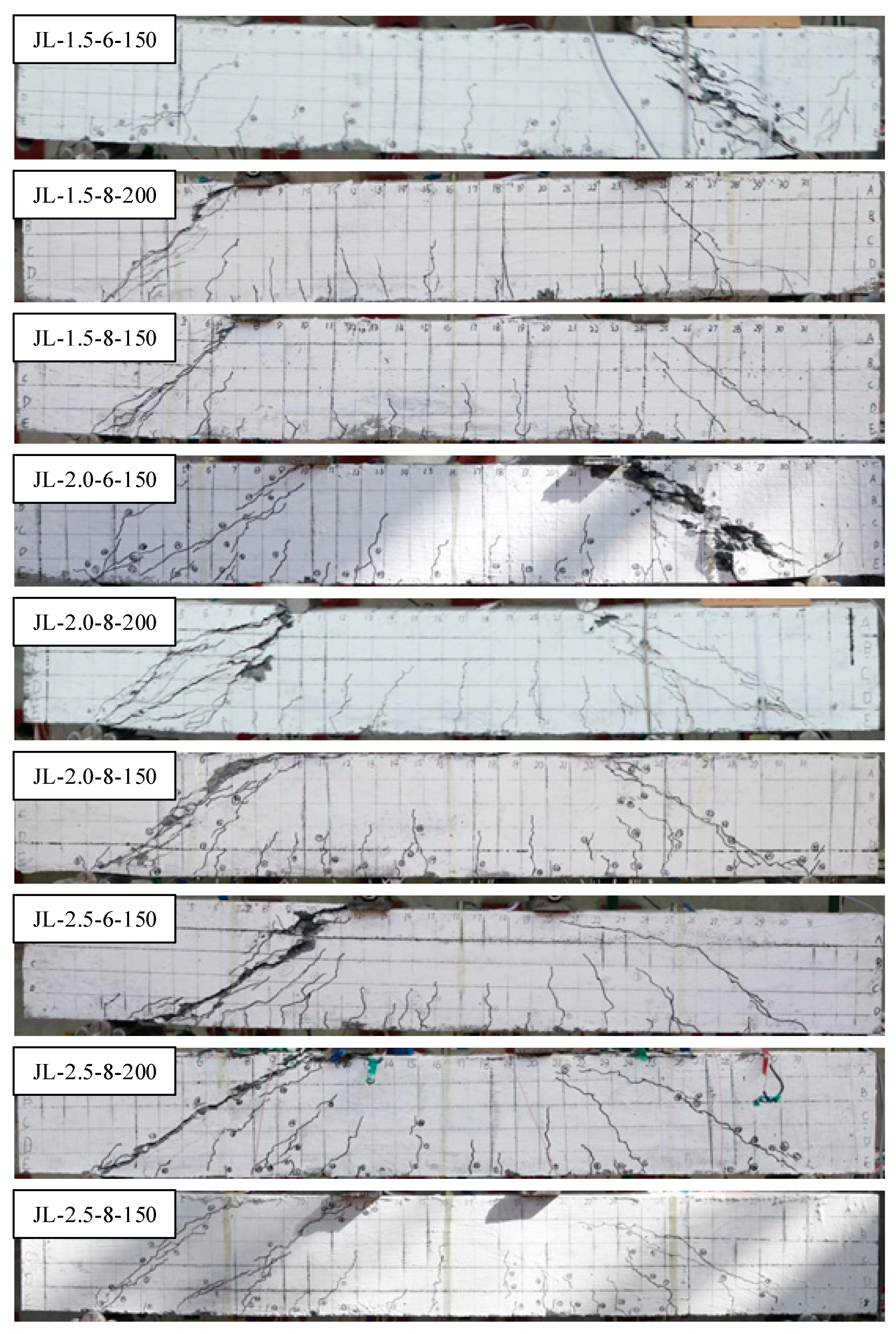
Table 2 shows the reinforced concrete beams of different sizes. The effective spans are all 1500 mm, but the shear span to effective depth ratios and Stirrup ratio are different. Taking JL-1.5-6-150 as an example, it indicates that the shear span to effective depth ratio is 1.5, the stirrup diameter is 6mm, and the stirrup spacing is 150 mm.
As shown in Fig. 4, each test beam was damaged in shear-compression damage. Critical diagonal cracks were formed along the line between the loading point and the support, and the concrete at the upper end of the diagonal cracks was crushed by the pressure, and obvious flexural deformation occurred. The cracks in the pure bending section in the span of the beam basically extended vertically upward, but none of them developed to the top of the test beam. The cracks in the shear-bending section are more abundant and denser, and intersect and penetrate each other to form a crack that runs through the height of the test beam.
2.2. Material Constitute of Concrete in FE Model
The stress-strain relationship employed in the finite element model corresponds to the constitutive relation of concrete as specified in the Code for the Design of Concrete Structures (GB 50010-2010)[
17]. During the elastic phase, the stress-strain relationship of concrete is determined by its Young's modulus
E and Poisson's ratio
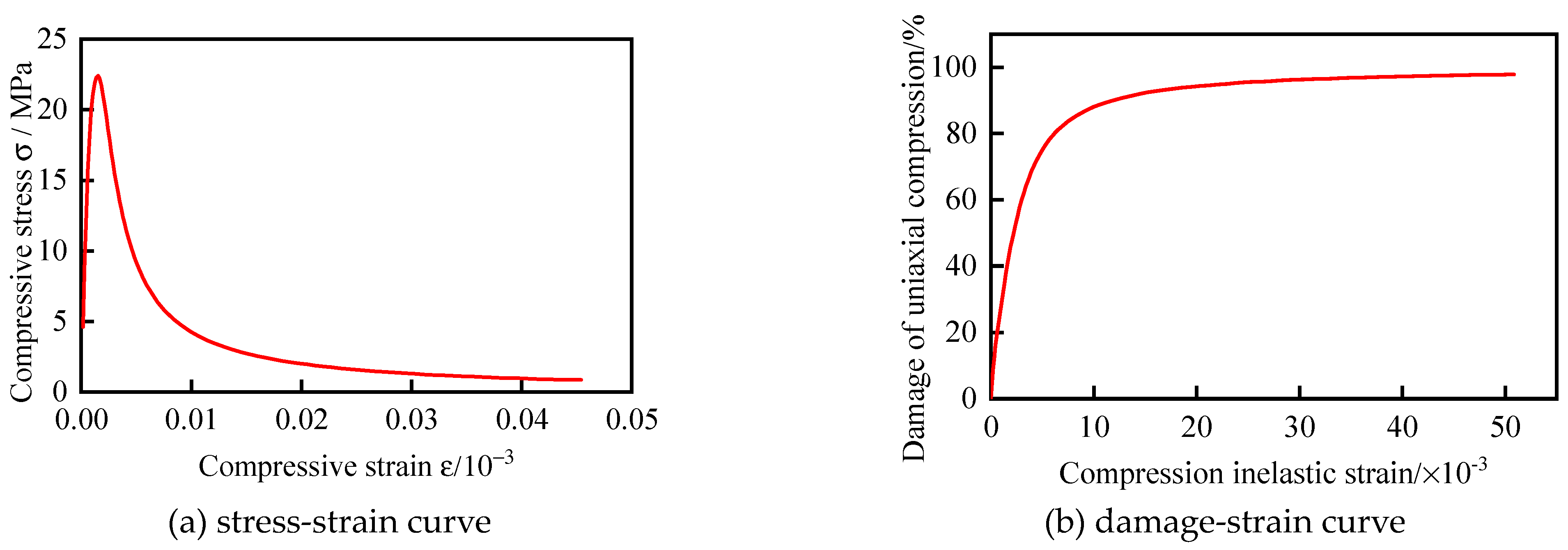
λ. In the inelastic phase, the stress-strain relationship of concrete is determined by the aforementioned code. The stress-strain relation of concrete under axial compression can be described by Eqs.(1)~(5).
where
represents the representative value of the axial compressive strength of concrete with a measured value of 22.4 MPa.
represents the modulus of elasticity of concrete which is taken as 30904.1 MPa;
represents the descending parameter value of the axial compression stress-strain curve of concrete, set as 1.563.
is the peak compressive strain of concrete corresponding to the representative value of axial compressive strength
of concrete, set as 0.001696;
is the evolution parameter of concrete axial compression damage.
Fig. 5 shows the stress-strain curves and axial compressive damage-strain curves of concrete under axial compression, respectively.
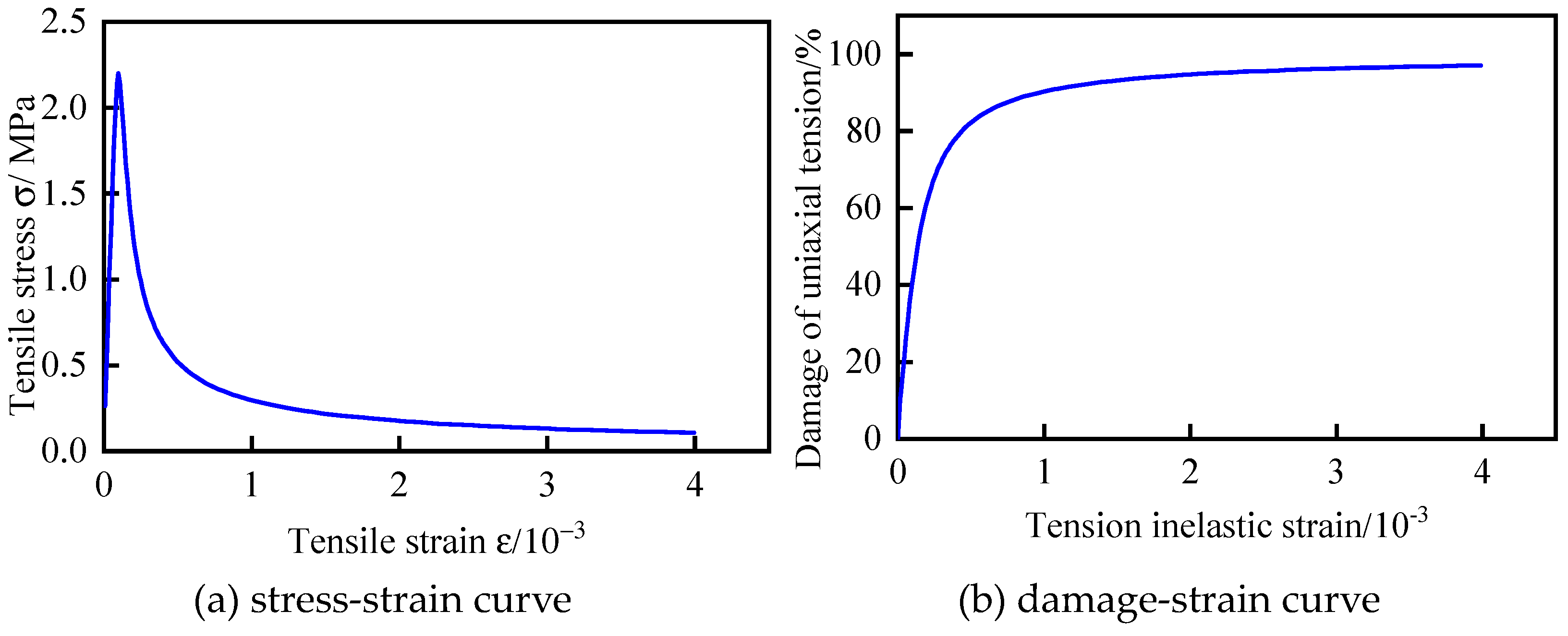
The axial tensile stress-strain curve of concrete can be calculated according to Eqs.(6)~(9).
where represents the representative value of the axial tensile strength of concrete with a measured value of 2.2 MPa; represents the descending parameter value of the axial tensile stress-strain curve of concrete, set as 1.53; is the peak tensile strain of concrete corresponding to the representative value of axial tensile strength, set as 0.0000998. is the evolution parameter of concrete axial tensile damage.
Fig. 6 show the axial tensile stress-strain curve of concrete and the axial tensile damage-strain curve of concrete respectively.
By combining the data calculated from the above formulas with the plastic damage constitutive model provided by Abaqus[
18], the shear failure test results of the simply-supported beams are verified accordingly. The hardening model in Abaqus follows von-mises yield criterion and has a good ability to simulate the nonlinear material of concrete.
2.3. Finite Element Model Building
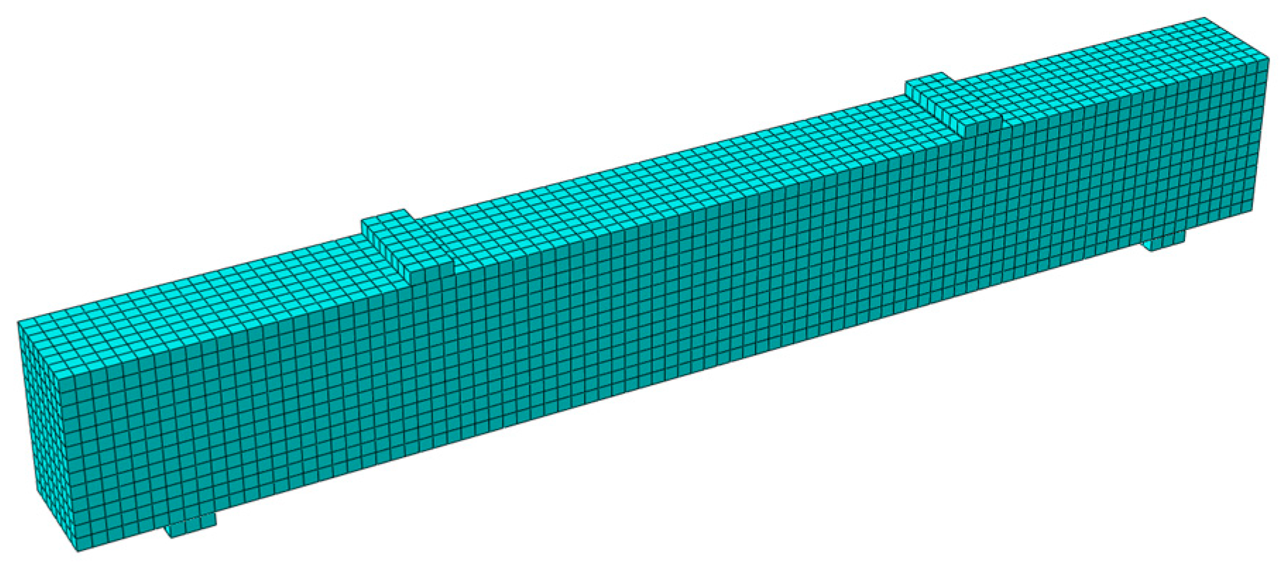
In Abaqus, three-dimensional solid C3D8R elements are used for concrete and two-node three-dimensional linear truss T3D2 elements are used for reinforcement. Rigid pads are used to transfer the concentrated forces and the pads are C3D8R elements. The reinforcement cage is embedded in the concrete.
The mesh type for the pads and concrete is a hexahedral mesh with a minimum size of 20 mm, and the reinforcement is a linear element with a minimum size of 30 mm to ensure sufficient accuracy. Previously, in order to more accurately simulate the dynamic damage evolution of concrete beams, an attempt was made to control the concrete mesh within 10 mm. However, due to the small mesh size, iterative calculations were difficult and the results did not converge and could not be completed. The meshing results of reinforced concrete beams are shown in Fig. 7.
2.4. Comparison of Experimental and Finite Element Modeling of Strains
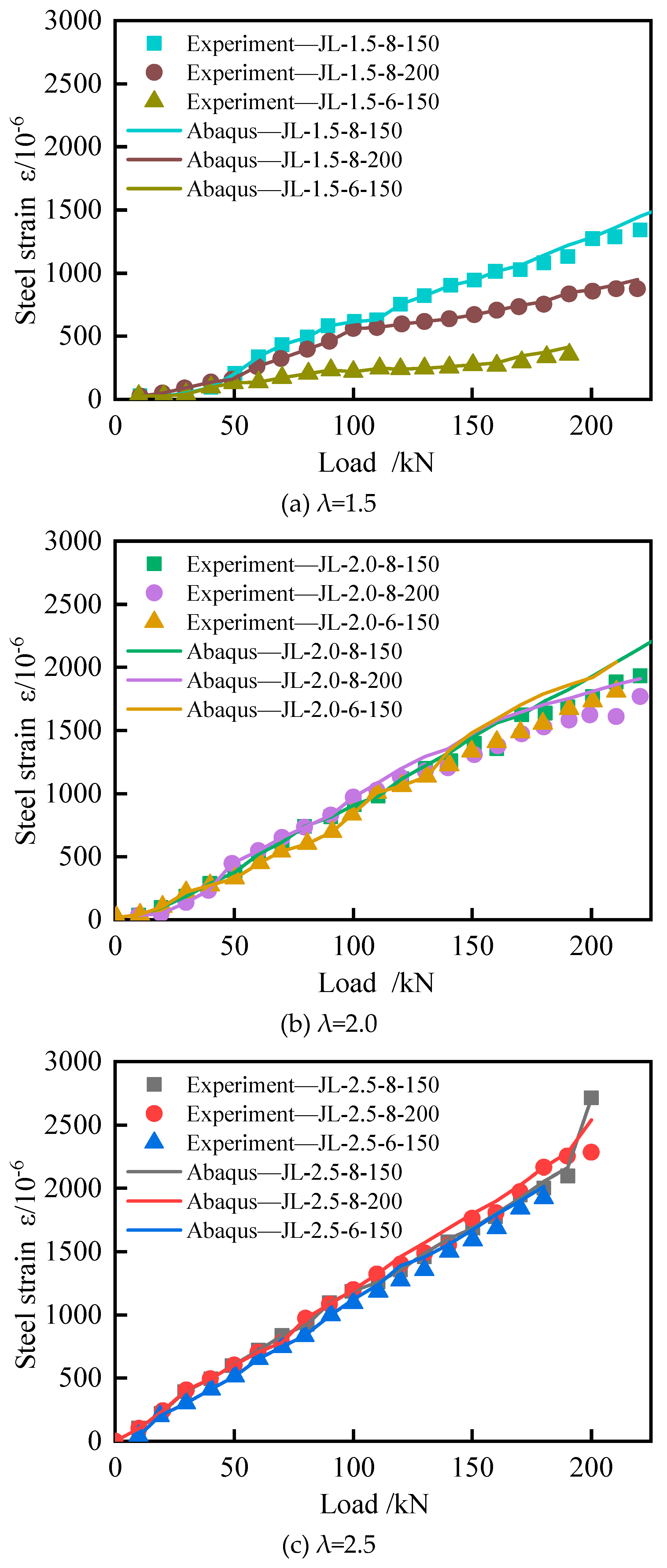
The load-strain curves of the bottom longitudinal reinforcement in the test are compared with the finite element simulation results as shown in Fig. 8, and the test results are in good agreement with the finite element simulation structure. It can be seen that for the RC beams with different shear-to-span ratios, the load-strain curves of the bottom longitudinal reinforcement are close to the linear relationship without inflection points, indicating that the longitudinal reinforcement at the bottom of the reinforced concrete beams has not yet reached the yield state.
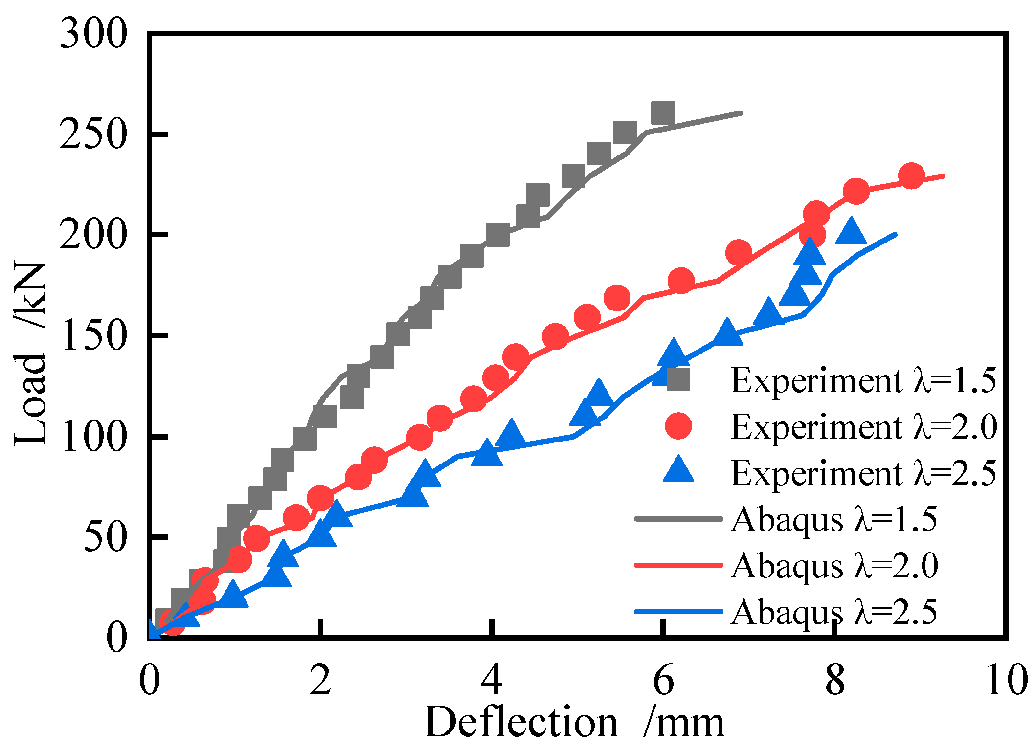
Based on the data from both the test and finite element simulation, as shown in Fig. 9, it is evident that the JL-2.5-8-200 test beam enters the elastic-plastic state earlier compared to the test beams with shear span to effective depth ratios of 1.5 and 2.0. When the load reaches approximately 70 kN, the test beam transitions into the elastic-plastic state, which aligns well with the test results. Throughout the entire loading process, the test beam exhibits a complete elastic-elastic-plastic damage progression. Initially, before the test beam develops cracks (elastic stage), the deflection increases linearly with the applied load. Once cracking initiates (elastic-plastic stage), the rate of deflection increase accelerates. As the load continues to increase (failure stage), the deflection grows rapidly.
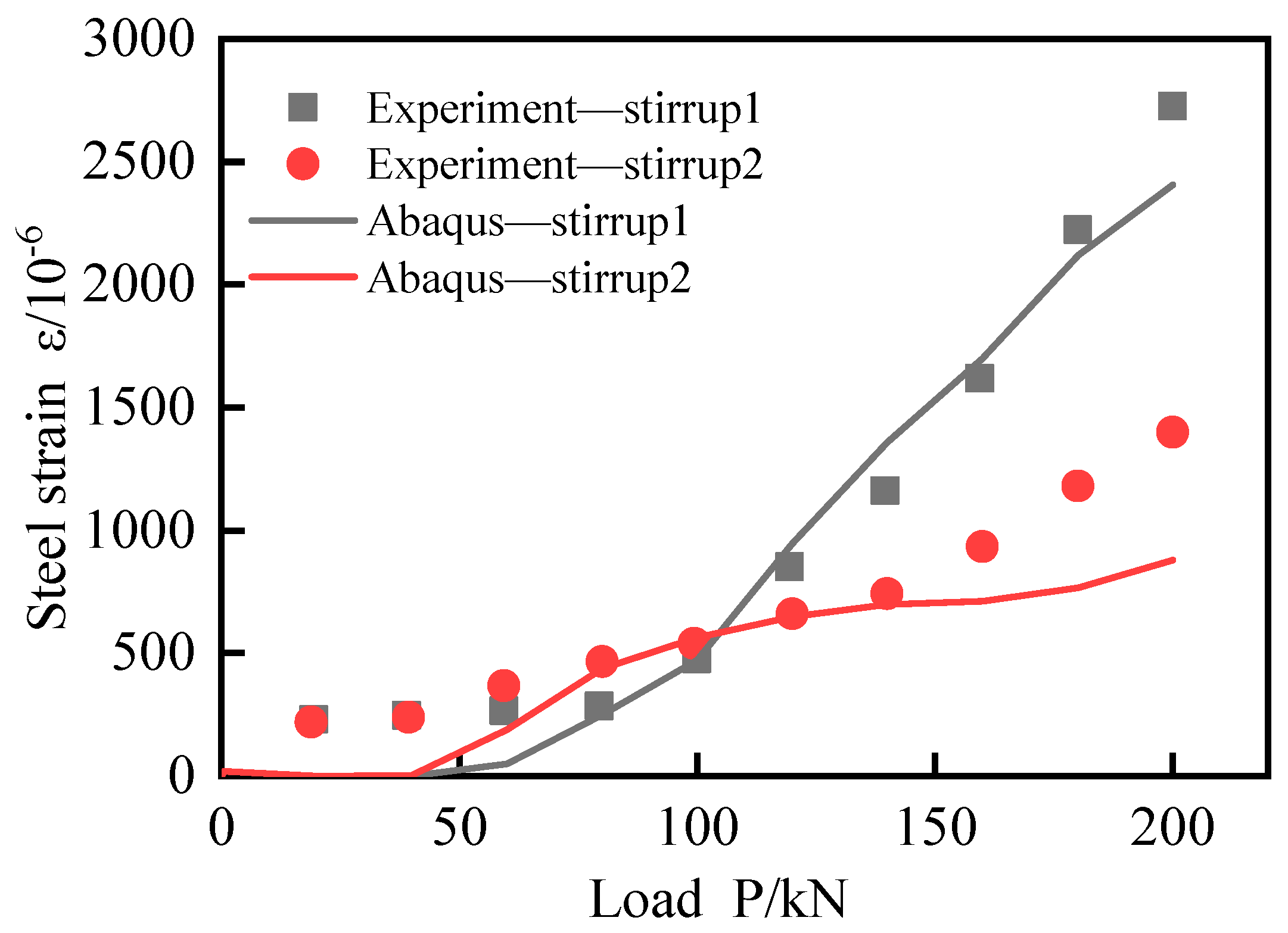
The load-stirrup strain curve shows that in the stage of slight damage, before the concrete cracks, the shear force in this stage is mainly borne by the concrete, and the shear force borne by the stirrup is very weak, so the stirrup strain of the test beam is extremely small and fluctuates around 0.
As the beam transitions into the stage of stable damage growth, the shear force is gradually transferred from the concrete to the stirrup, particularly when the bending shear inclined crack appears. As a result of the shear stress, the stirrup strain increases gradually. With the continued increase of shear force, multiple abdominal shear oblique cracks appear, and their widths continue to expand. The shear force borne by the stirrup increases significantly and reaches a second inflection point, where the stirrup strain increases rapidly. Fig. 10 indicates that the strain at Stirrup 1 agrees well with the test results, whereas the strain growth rate at Stirrup 2 is lower than the test results in the comparison between the original test and finite element simulation results but the trend remains the same.
The longitudinal strain-load curve, stirrup strain-load curve and deflection curve are in good agreement with those obtained by Abaqus finite element analysis, but the interaction and slip between concrete and steel bars are not considered, resulting in a small strain and calculated deflection of steel bars, that is, a large calculated stiffness.
2.5. Comparison of Experimental and Finite Element Modeling of Cracks
In the process of concrete expansion, cracks often bifurcate and skew due to the lack of coordination in deformation among different materials within the concrete. The development direction of cracks is uncertain. In concrete members, the presence and expansion of cracks serve as direct indicators of damage to the member. Therefore, evaluating the degree of damage to concrete based on the progression of cracks holds practical significance.
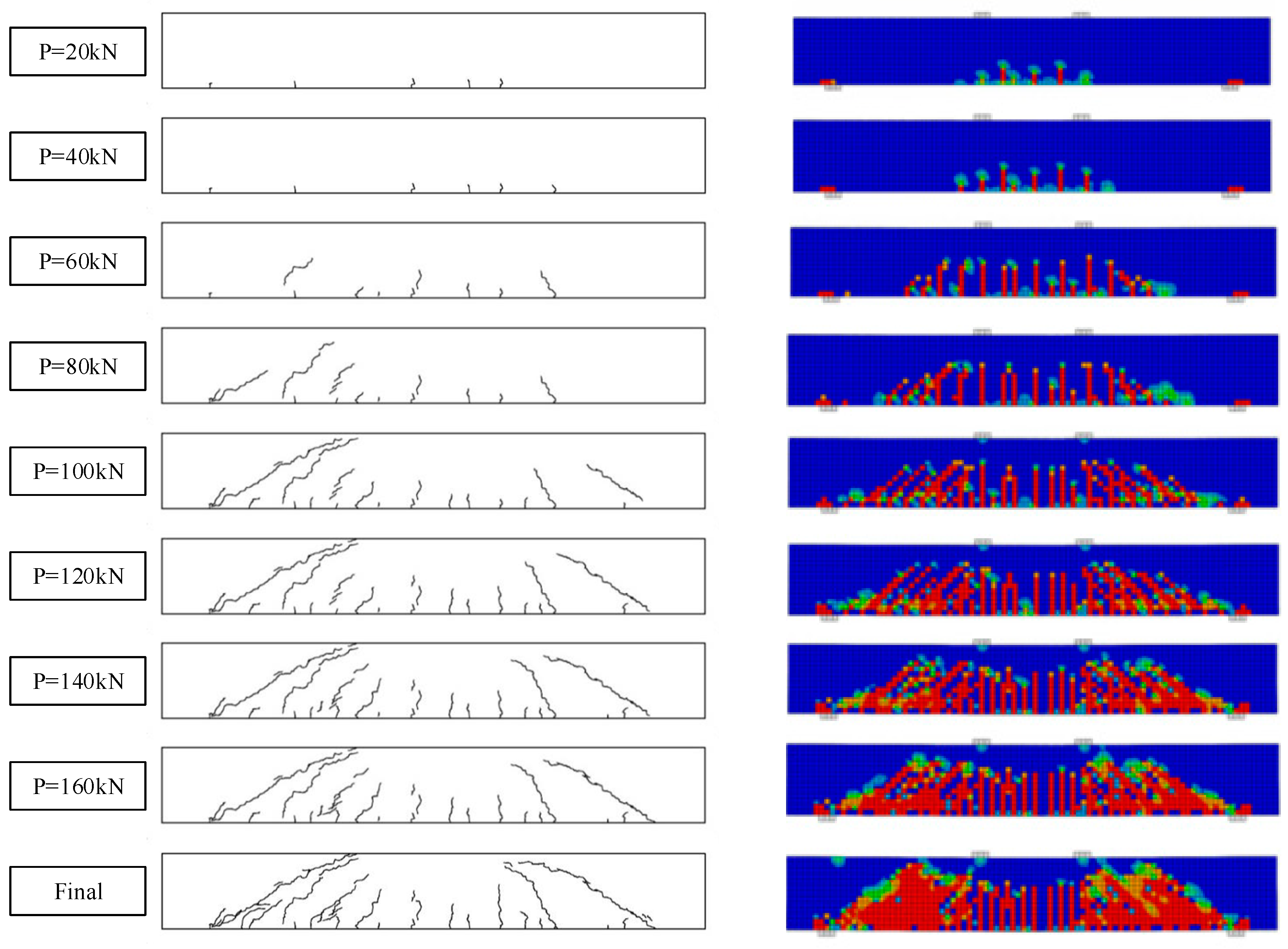
As shown in Fig. 11, in the process of shear failure of the test beam, due to the stress concentration at the loading point and support, the cracking phenomenon occurs at the support. Stress concentration at the loading point and support led to cracking in these areas. As the load increased, the mid-span bending moment reached the cracking moment, resulting in the appearance of the first crack in the pure bending section of the concrete beam. The test beam entered the stage of damage stabilization development, with small cracks appearing at the bottom of the shear bending section and a relatively stable development. New cracks appeared on the surface of the test beam at the beginning of loading and expanded steadily as the load increased. At 60kN load, cracks in the pure bending section extended upwards, and a bending shear inclined crack developed adjacent to this section due to the combined effect of shear force and bending moment. At 120kN load, the depth of the web shear inclined crack near the upper surface of the test beam continued to increase. When the load reached 140kN, most of the concrete in the test beam was crushed, and new cracks appeared in the shear section, expanding continuously. Eventually, the diagonal cracks in the shear section connected with each other, and there was a slight increase in the depth of the cracks in the pure section.
Fig. 11 illustrates the damage process of the beam. The concrete plastic damage model, while useful for quantitatively deriving the percentage of concrete damage, may not fully capture the width, spacing, and depth of macroscopic cracks. However, it can qualitatively demonstrate the development direction and expansion process of cracks through the DAMAGET distribution. It provides quantitative information on the extent of concrete damage, a complementary qualitative assessment of crack development and expansion is facilitated by the DAMAGET distribution.
3. Simulation of Frame Joints with Floor Slabs
3.1. Analysis Model
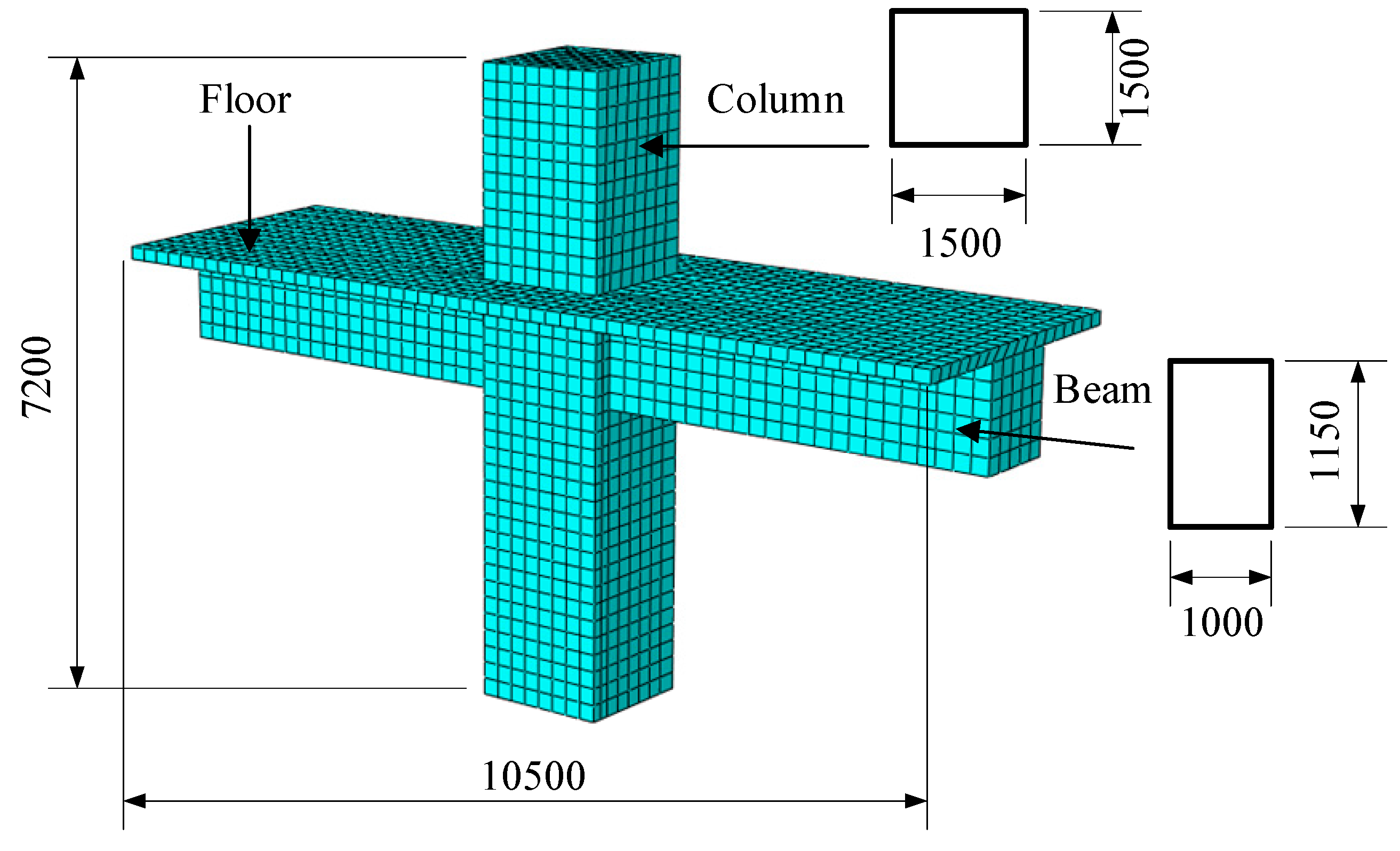
For Jinan Yao Qiang Airport, cracks of 0.5mm width are prone to appear at the end of beams in the 18m-span joint area. In order to understand the development process and final failure pattern of cracks, and then accurately control crack expansion, Abaqus simulation is carried out on typical beam-column joints in M1 area. The section size of the joint beam in the research test is b×h=1000mm×1150mm, the section size of the test joint column is b×h=1500mm×1500mm, the total length of the joint is 10500mm, and the total height is 7200mm. The grid division results of the model are shown in Fig. 12.
3.2. Loading Mode
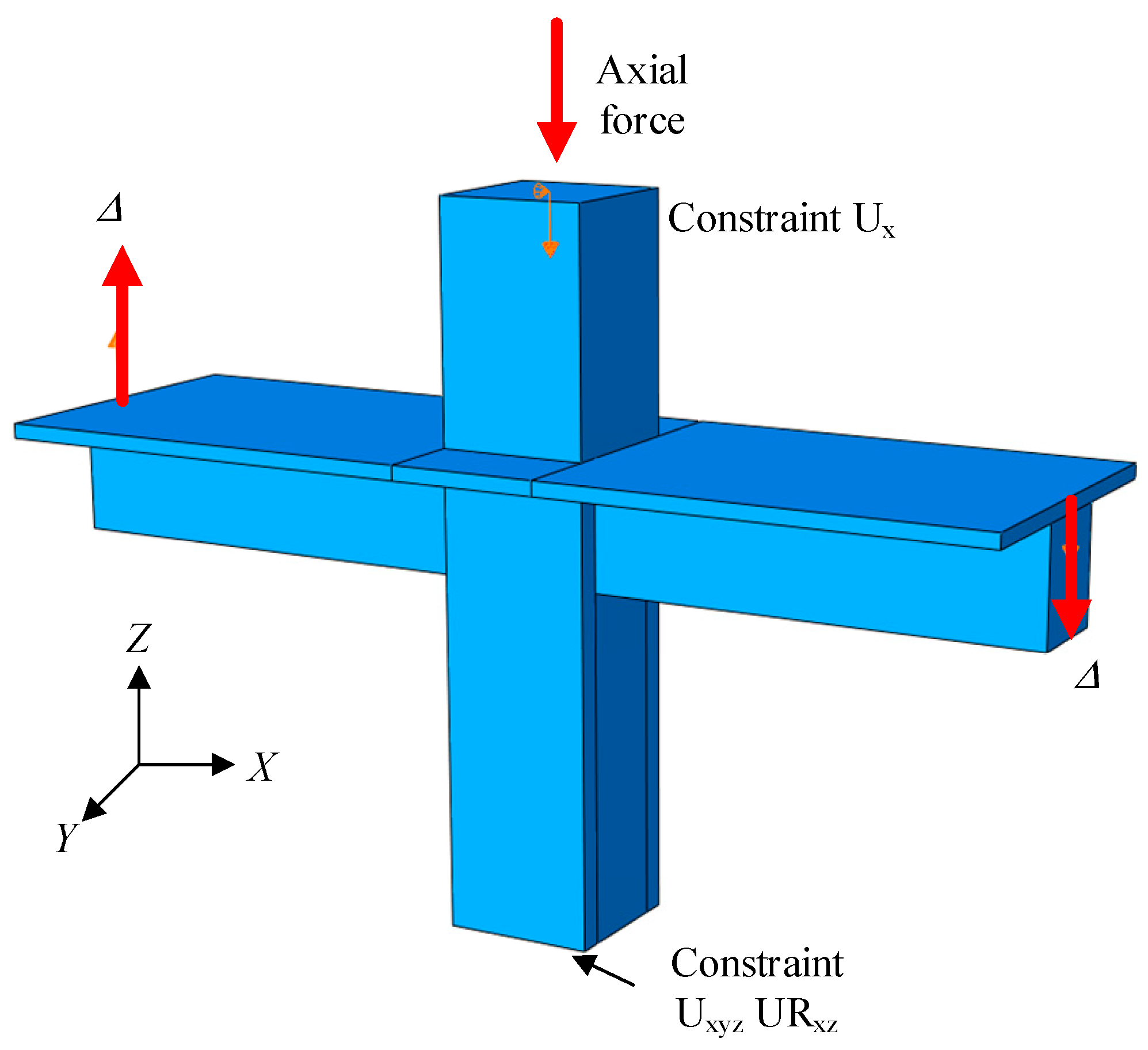
In order to accurately simulate the effect of horizontal earthquake on the nodes, it is assumed that only the rotation of the lower end of the column along the Y axis is released and only the displacement of the upper end of the column along the X axis is fixed, using the coordinate axes in Fig. 13 as the standard. The seismic action is simulated by applying reciprocating displacement Δ at the beam end.
Different from simply supported beams, considering that it is difficult to fully match the mesh of beam-column joints, Abaqus will be difficult to converge if the large stiffness pad is continued to be bound to the surface of the concrete beam ends. Therefore, in order to better simulate the dynamic characteristics of the frame joints under reciprocating loads, the concrete section of the beam ends is coupled to a reference point, and the reciprocating loads are input on the point. The loading method of the joint with floor frame adopted is shown in Fig. 13.
3.3. Loading Regime
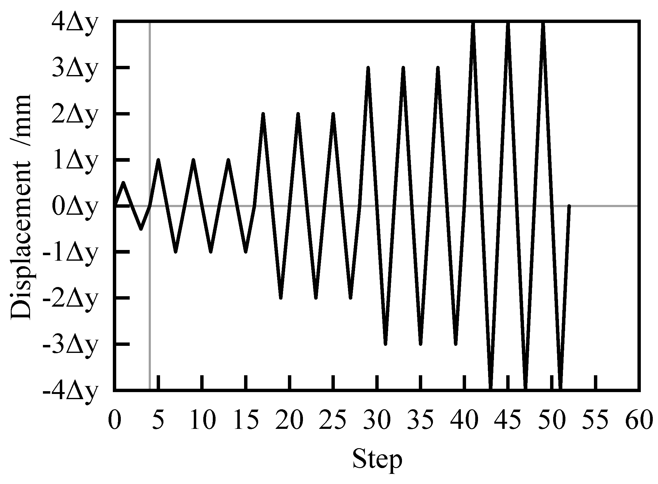
Firstly, a constant axial force of 3.465×10⁴ kN with an axial compression ratio of 0.4 is slowly applied to the top of the column by a vertical hydraulic jack to simulate the axial compression transmitted by the superstructure to the column. The method of reciprocating loading was used in the analysis. According to Building Seismic Test Method Regulations JGJ/T101-2015, the test specimen is preloaded with no more than 30% of the calculated cracking load value, and then the reciprocating load is applied by using the mixed load and displacement control loading system. Before cracking, the test specimen was loaded by load control, and the load was repeated according to 0.5 times of the estimated cracking load. The corresponding displacement during cracking is Δ=1.79 mm. After cracking, reciprocating loading is adopted to apply vertical displacement Δtotal (Δtotal =4Δ) to the coupling point of the beam end for displacement loading. Each stage of loading reciprocates three times, and the loading system is shown in Fig. 14.
4. Calculation Results and Analysis
4.1. Stress Distribution
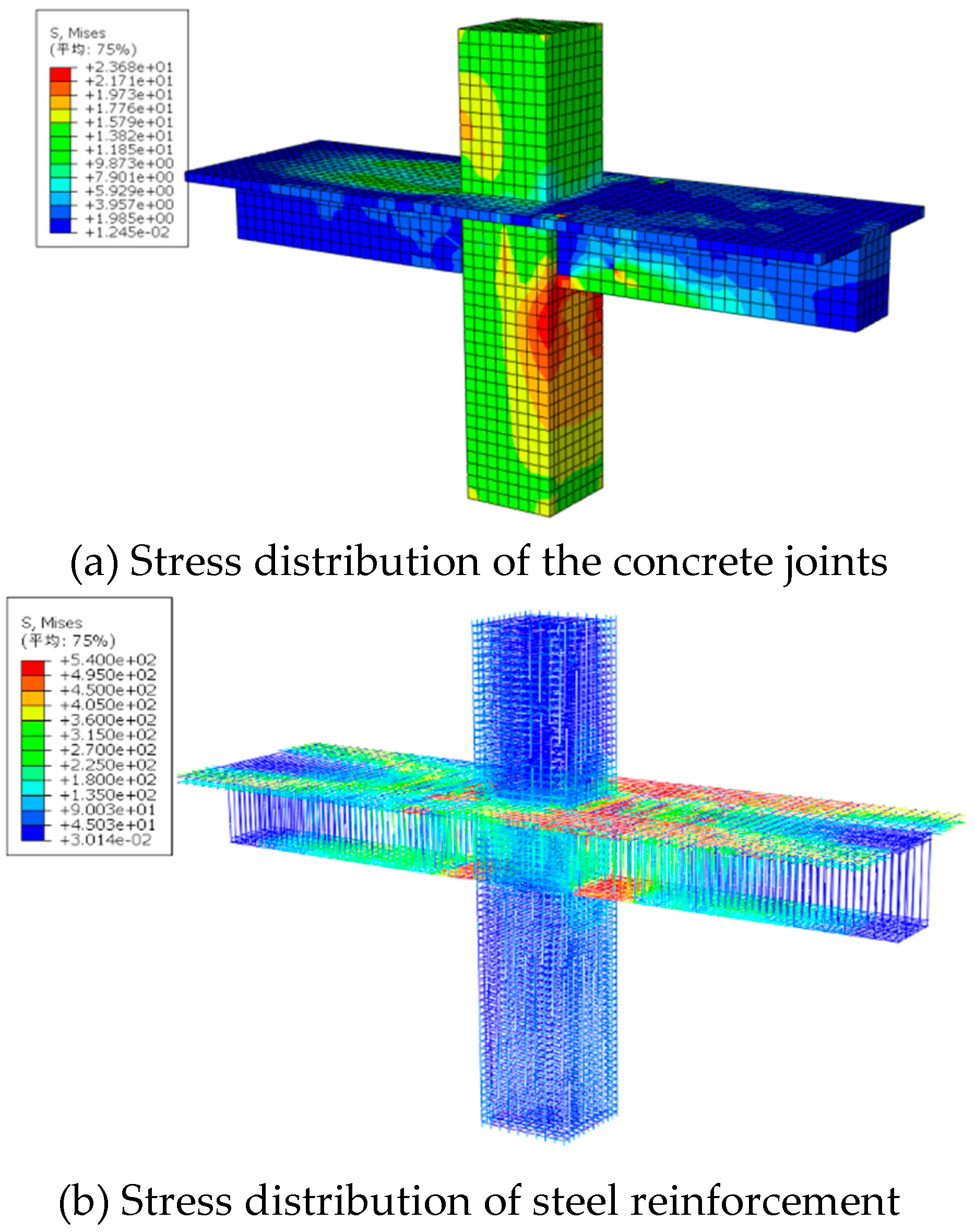
Under the action of reciprocating loads, the stress of the concrete is shown in Fig. 15(a). The compression of concrete columns in the joint core area is more obvious when reciprocating loads are applied. Fig. 15(b) shows that under vertical reciprocating load, the absolute strain values of the longitudinal bars at the end of the beam joints with floor plates are relatively concentrated, so the anchorage length of the longitudinal bars at the end of the beam should be carefully considered in the structural design.
4.2. Hysteretic Properties and Skeleton Curves
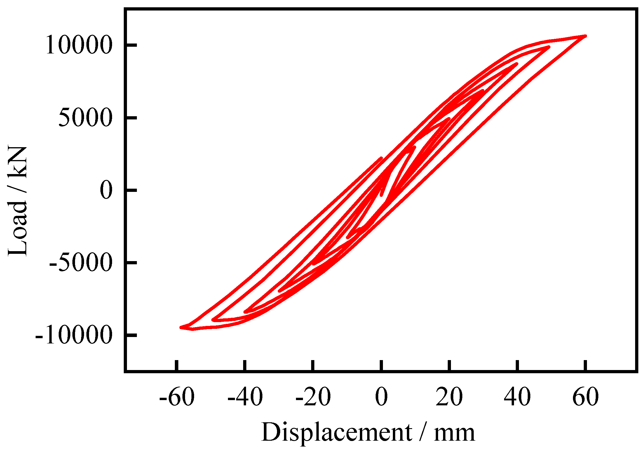
Hysteretic curve, also known as restoring force curve, it refers to the load-displacement curve of a structure or member obtained under the action of cyclic force or displacement. The hysteresis curve can reflect the strength degradation, stiffness degradation, deformation characteristics and energy dissipation capacity of the joint specimen during the cyclic and reciprocating stress process, which is a comprehensive reflection of the seismic performance of the specimen. The hysteresis curve of the joint is shown in Fig. 16.
For this joint, when the displacement Δ<12mm, the specimen is in an elastic state, the hysteresis ring is fusiform, and there is no residual deformation after unloading. When 12≤Δ< 26mm, the hysteresis ring becomes a bow, the residual deformation increases, and the structure enters the elastoplastic state. When Δ≥26mm, the hysteresis ring enters the inverted S shape, and the residual deformation increases after unloading, entering the plastic state.
4.3. Reinforcement Strain
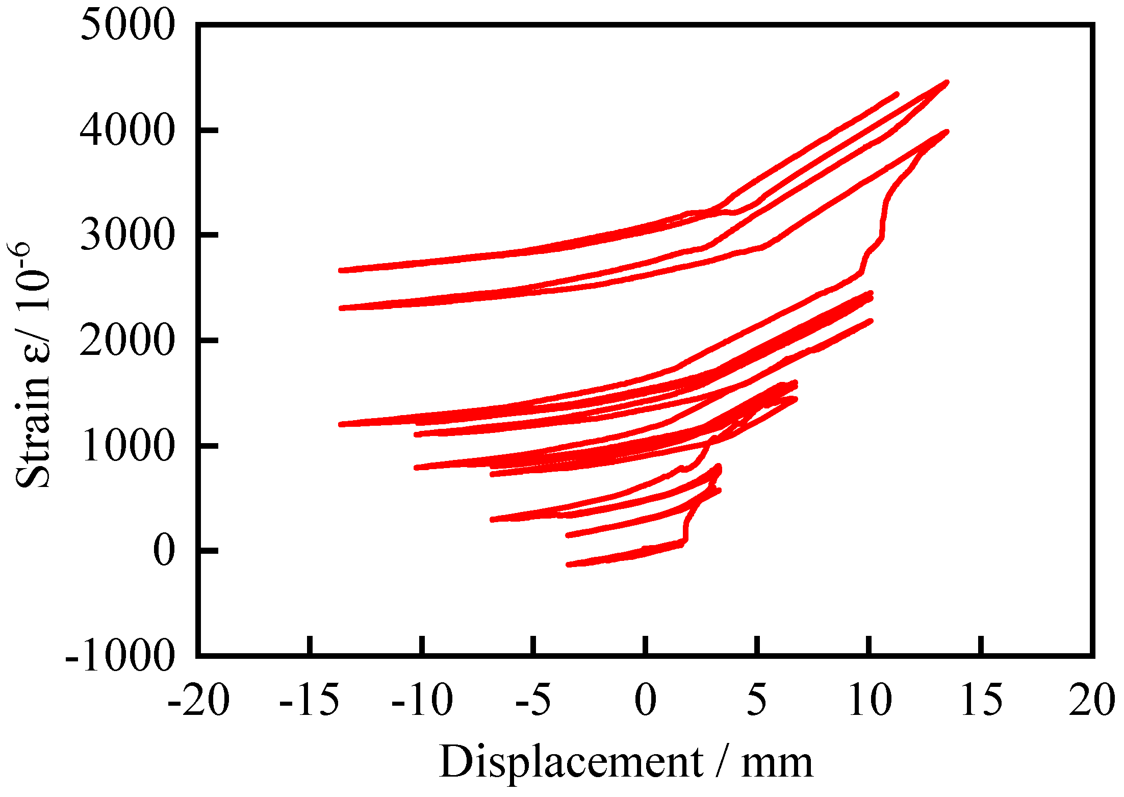
Take the upper longitudinal steel bar with joint 10mm near the column edge. During the whole loading process, the longitudinal steel bar of the upper beam is strained under positive loading, while the longitudinal steel bar of the upper beam is compressed under negative loading, as shown in Fig. 17. The strain value of longitudinal reinforcement fluctuates in the range of -5×10⁻⁶ ~ 15×10-6, and does not reach the yield strain value of reinforcement.
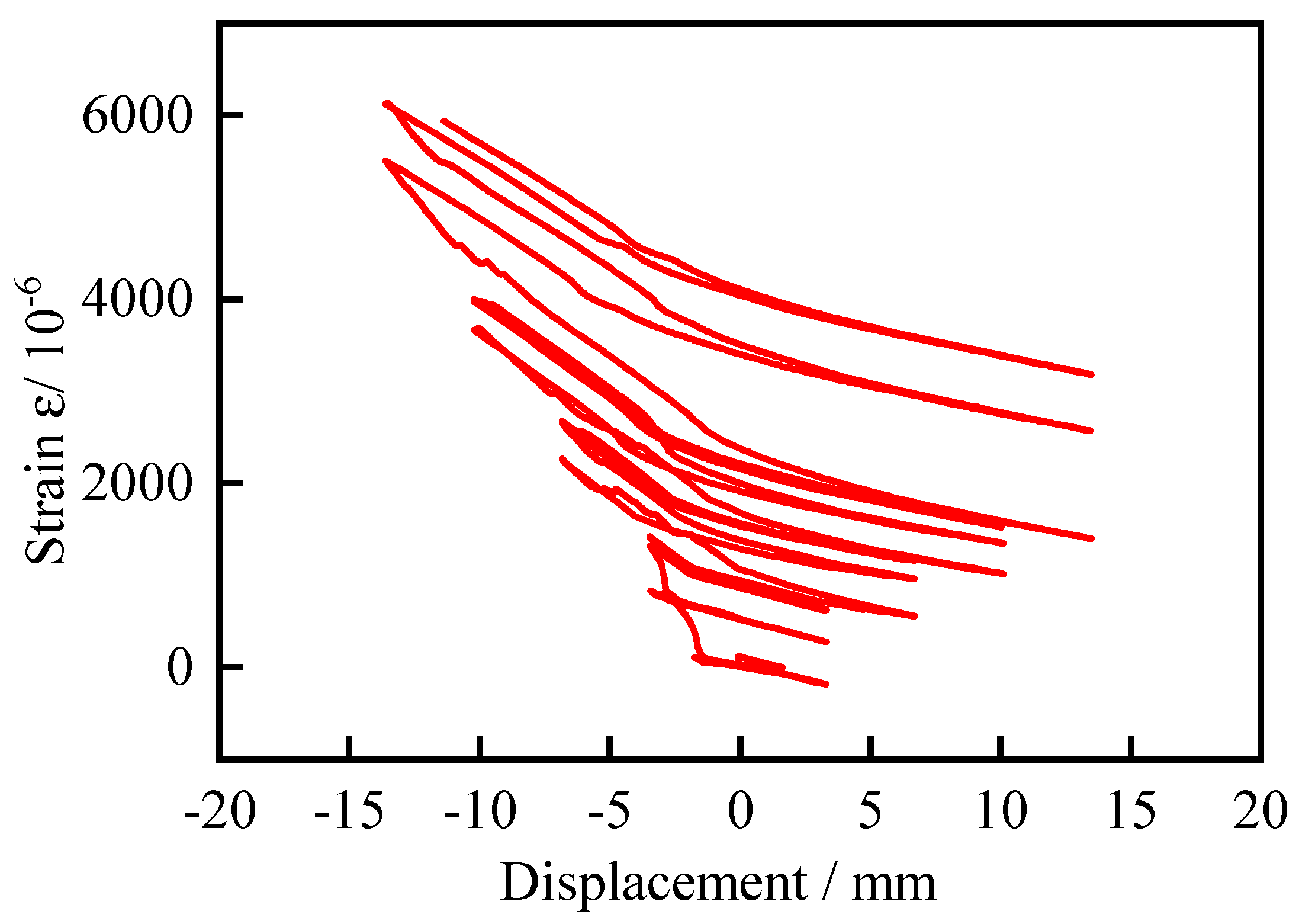
Take the lower longitudinal steel bar with joint 10mm close to the beam end. When the beam is loaded negatively, the longitudinal steel bar under the beam is strained, as shown in Fig. 18. The strain value of the longitudinal steel bar fluctuates between -210×10-6 and 6200×10-6, and does not reach the yield strain value.
4.4. Concrete Damage
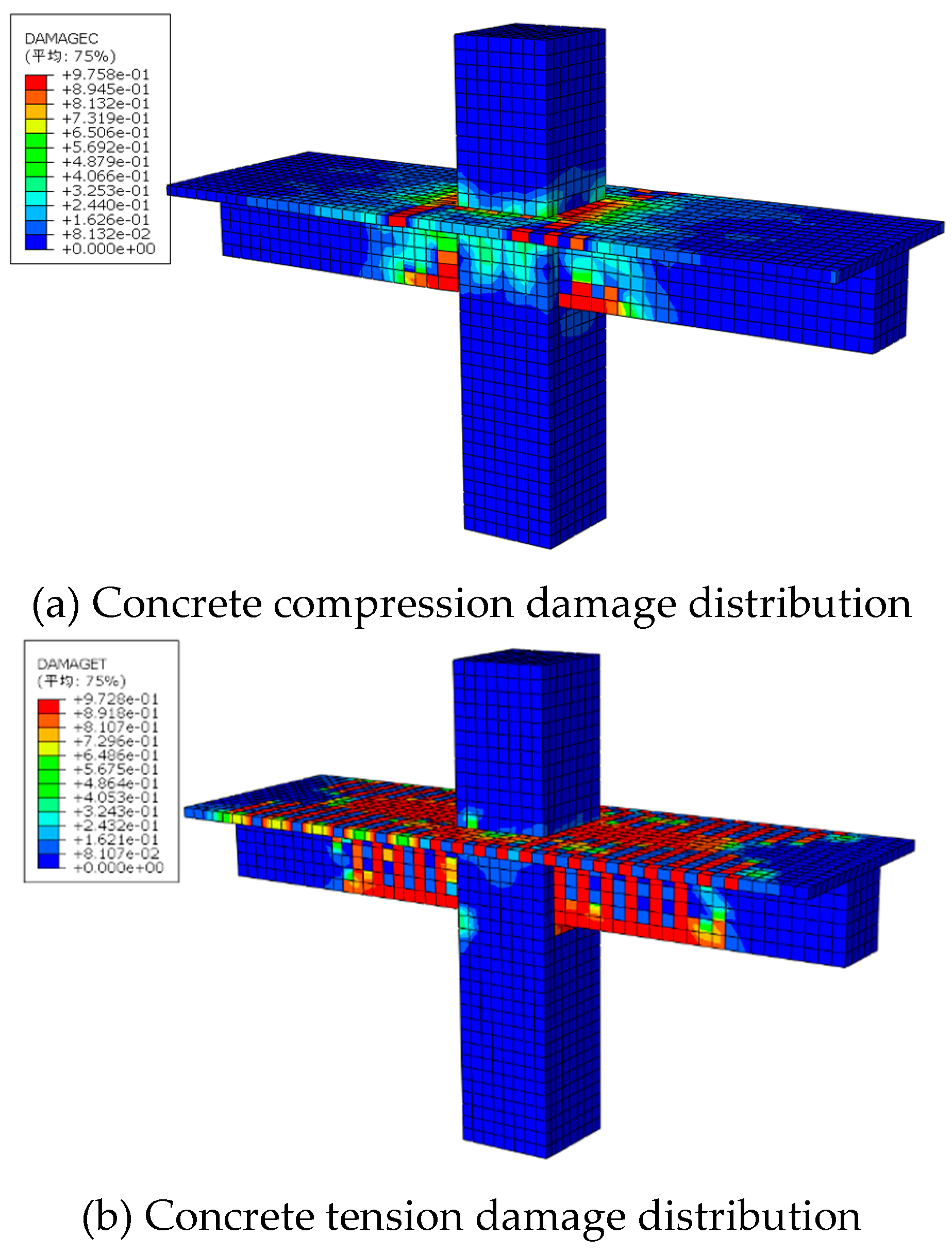
The diagram depicting tensile and compression damage of concrete is illustrated in Fig. 19. The concrete material exhibits robust compressive resistance and a low degree of damage, which is concentrated at the beam ends. However, its tensile strength is comparatively weak, resulting in a higher degree of damage. As depicted in this figure, the degree of crack damage in the floor surpasses that of the beam. Tensile damage manifests as primarily flexural cracks perpendicular to the beam axis, with the crack spacing gradually decreasing from the beam ends towards both sides.
5. Conclusions
The variations in strain, deflection, and crack expansion of rebar under load are primarily compared and tested, while considering the influence of mesh size and concrete constitutive. Subsequently, the stress, strain, and concrete damage of both concrete and rebar at joints in practical engineering applications are analyzed, yielding the following results:
(1) The nonlinear simulation constitutive calculated according to the formula in GB 50010-2010 proves to be more suitable. The obtained axial tensile and compressive stress-strain curves, as well as the axial tensile and compressive damage-strain curves of concrete, can more accurately simulate the test results.
(2) Shear and compressive failure occurred in all the simply supported test beams, and the strain changes of reinforcement during the failure of test beams were qualitatively analyzed. The strain of the longitudinal bar at the bottom of the beam shows an approximately linear increase in both test and simulation results, with no bending failure observed in the test beam.
(3) The Abaqus concrete damage plastic model is unable to quantitatively reflect the width, spacing, and depth of macroscopic cracks. However, it can qualitatively illustrate the development direction and expansion process of cracks through the DAMAGET diagram.
(4) In the actual project simulated using the Abaqus concrete damage plastic model, the joint cracks of the frame with the floor primarily manifest as flexural cracks, with the concrete damage degree of the floor exceeding that of the beam.
Figure 1.
Schematic diagram of simply supported beam test.
Figure 1.
Schematic diagram of simply supported beam test.
Figure 2.
Test beam stirrup strain gauge position.
Figure 2.
Test beam stirrup strain gauge position.
Figure 3.
Reinforced concrete beam loading test device from reference [
16].
Figure 3.
Reinforced concrete beam loading test device from reference [
16].
Figure 4.
Test results of reinforced concrete beams from reference [
16].
Figure 4.
Test results of reinforced concrete beams from reference [
16].
Figure 5.
Stress-strain and damage relationship curves of concrete under axial compression.
Figure 5.
Stress-strain and damage relationship curves of concrete under axial compression.
Figure 6.
Stress-strain and damage relationship curves of concrete under axial tensile.
Figure 6.
Stress-strain and damage relationship curves of concrete under axial tensile.
Figure 7.
Abaqus mesh model.
Figure 7.
Abaqus mesh model.
Figure 8.
Load-strain comparison curve between test and finite element.
Figure 8.
Load-strain comparison curve between test and finite element.
Figure 9.
Load-strain comparison curves of test- deflection element.
Figure 9.
Load-strain comparison curves of test- deflection element.
Figure 10.
Test stirrup strain-load curve.
Figure 10.
Test stirrup strain-load curve.
Figure 11.
Test and simulate crack propagation process.
Figure 11.
Test and simulate crack propagation process.
Figure 12.
Abaqus grid division with floor frame.
Figure 12.
Abaqus grid division with floor frame.
Figure 13.
Loading mode diagram.
Figure 13.
Loading mode diagram.
Figure 14.
Loading regime diagram.
Figure 14.
Loading regime diagram.
Figure 15.
Stress distribution in reinforced concrete joints with floor slabs.
Figure 15.
Stress distribution in reinforced concrete joints with floor slabs.
Figure 16.
Load-deformation Angle hysteresis curve.
Figure 16.
Load-deformation Angle hysteresis curve.
Figure 17.
Strain-deformation curve of the upper row of rebar.
Figure 17.
Strain-deformation curve of the upper row of rebar.
Figure 18.
Strain-deformation curve of the lower row of rebar.
Figure 18.
Strain-deformation curve of the lower row of rebar.
Figure 19.
Concrete Damage Distribution of the joint.
Figure 19.
Concrete Damage Distribution of the joint.
Funding
This research was funded by the Fundamental Research Funds for the Central Universities of China grant number FRF-TP-22-117A1.
References
- He H X, Tian S Y, Zhang Y Y. Refined fatigue damage assessment of RC beam based on fractal characteristics of cracks. Structures 2022, 46, 1595–1603. [Google Scholar] [CrossRef]
- P Kumar Mehta. Structure, Properties and Materials of Concrete. McGraw-Hill: 1993.
- Naotunna C N, Samarakoon S M S M K, Foss K T. Experimental investigation of crack width variation along the concrete cover depth in reinforced concrete specimens with ribbed bars and smooth bars. Case Studies in Construction Materials 2021, 15, e00593. [Google Scholar] [CrossRef]
- Shayanfar M A, Farnia S M H, Ghanooni-Bagha M; et al. The effect of crack width on chloride threshold reaching time in reinforced concrete members. Asian Journal of Civil Engineering 2020, 21, 625–637. [Google Scholar] [CrossRef]
- Wang T, Li C H, Zheng J J; et al. Consideration of coupling of crack development and corrosion in assessing the reliability of reinforced concrete beams subjected to bending. Reliability Engineering & System Safety 2023, 233, 109095. [Google Scholar]
- Wang Q, Song H L, Lu C L; et al. Shear performance of reinforced ultra-high performance concrete rectangular section beams. Structures 2020, 27, 1184–1194. [Google Scholar] [CrossRef]
- Cavagnis F, Ruiz M F, Muttoni A. Shear failures in reinforced concrete members without transverse reinforcement: An analysis of the critical shear crack development on the basis of test results. Engineering Structures 2015, 103, 157–173. [Google Scholar] [CrossRef]
- Rombach G A, Faron A. Numerical analysis of shear crack propagation in a concrete beam without transverse reinforcement. Procedia Structural Integrity 2019, 17, 766–773. [Google Scholar] [CrossRef]
- Yang, Y. Shear Behaviour of Reinforced Concrete Members without Shear Reinforcement: a New Look at an Old Problem. TU Delft, Delft University of Technology, 2014.
- Li Z, Li Y, Yi W J; et al. Shear Mechanism and Size Effect of RC Deep Beams without Stirrups Based on Crack Kinematics in Tests. Journal of Structural Engineering 2023, 149, 04023159. [Google Scholar] [CrossRef]
- Yang K H, Ashour A F. Modification Factor for Shear Capacity of Lightweight Concrete Beams. Aci Structural Journal 2015, 112, 485–492. [Google Scholar] [CrossRef]
- Yin Y Y, Hu S W, Liang C F; et al. Crack extension resistance for a general three-point bending concrete beam. Engineering Fracture Mechanics 2023, 290, 109490. [Google Scholar] [CrossRef]
- Yin Y J, Ren Q W, Shen L. Study on the effect of aggregate distribution on mechanical properties and damage cracks of concrete based on multifractal theory. Construction and Building Materials 2020, 262, 120086. [Google Scholar] [CrossRef]
- Mukhtar F, El-Tohfa A. A review on fracture propagation in concrete: Models, methods, and benchmark tests. Engineering Fracture Mechanics 2023, 281, 109100. [Google Scholar] [CrossRef]
- Zhang X F, Shi R, Dai H B; et al. Simulation and research on temperature field of Taishan roller compacted concrete gravity dam. IOP Conference Series Earth and Environmental Science 2019, 237, 3. [Google Scholar] [CrossRef]
- Zhao Z, H. Experimental study on fractal crack propagation law of reinforced concrete shear beam. Xinjiang University, 2020.
- GB 50010-2010 Code for design of concrete structures. Beijing: China Architecture and Building Press, 2010.
- ABAQUS Analysis User’s Manual v6. 13 [M]. ABAQUS Inc, 2013.
Table 1.
Material properties.
Table 1.
Material properties.
| Component |
Diameter/mm |
Material |
Yield strength/MPa |
| Longitudinal |
22 |
HRB335 |
379.35 |
| Strut |
12 |
HPB300 |
312.55 |
| Stirrup |
6/8 |
HPB300 |
312.55 |
Table 2.
Parameters of reinforced concrete beams.
Table 2.
Parameters of reinforced concrete beams.
| Species |
Effective span/mm |
shear span to effective depth ratio |
Concentrated load span/mm |
Stirrup spacing |
Stirrup ratio/% |
| JL-1.5-6-150 |
1500 |
1.5 |
338 |
6@150 |
0.25 |
| JL-1.5-8-200 |
1500 |
1.5 |
338 |
8@200 |
0.36 |
| JL-1.5-8-150 |
1500 |
1.5 |
338 |
8@150 |
0.45 |
| JL-2.0-6-150 |
1500 |
2.0 |
450 |
6@150 |
0.25 |
| JL-2.0-8-200 |
1500 |
2.0 |
450 |
8@200 |
0.36 |
| JL-2.0-8-150 |
1500 |
2.0 |
450 |
8@150 |
0.45 |
| JL-2.5-6-150 |
1500 |
2.5 |
563 |
6@150 |
0.25 |
| JL-2.5-8-200 |
1500 |
2.5 |
563 |
8@200 |
0.36 |
| JL-2.5-8-150 |
1500 |
2.5 |
563 |
8@150 |
0.45 |
|
Disclaimer/Publisher’s Note: The statements, opinions and data contained in all publications are solely those of the individual author(s) and contributor(s) and not of MDPI and/or the editor(s). MDPI and/or the editor(s) disclaim responsibility for any injury to people or property resulting from any ideas, methods, instructions or products referred to in the content. |
© 2023 by the authors. Licensee MDPI, Basel, Switzerland. This article is an open access article distributed under the terms and conditions of the Creative Commons Attribution (CC BY) license (http://creativecommons.org/licenses/by/4.0/).

