Submitted:
28 November 2023
Posted:
29 November 2023
You are already at the latest version
Abstract
Keywords:
1. Introduction
2. Background
3. Methodology
3.1. Preliminaries
3.2. The end-effector motion constraints
3.3. The constrained robot kinematics model
3.4. The manipulability ellipsoid of the constrained motion
4. Numerical Experiments and Discussion
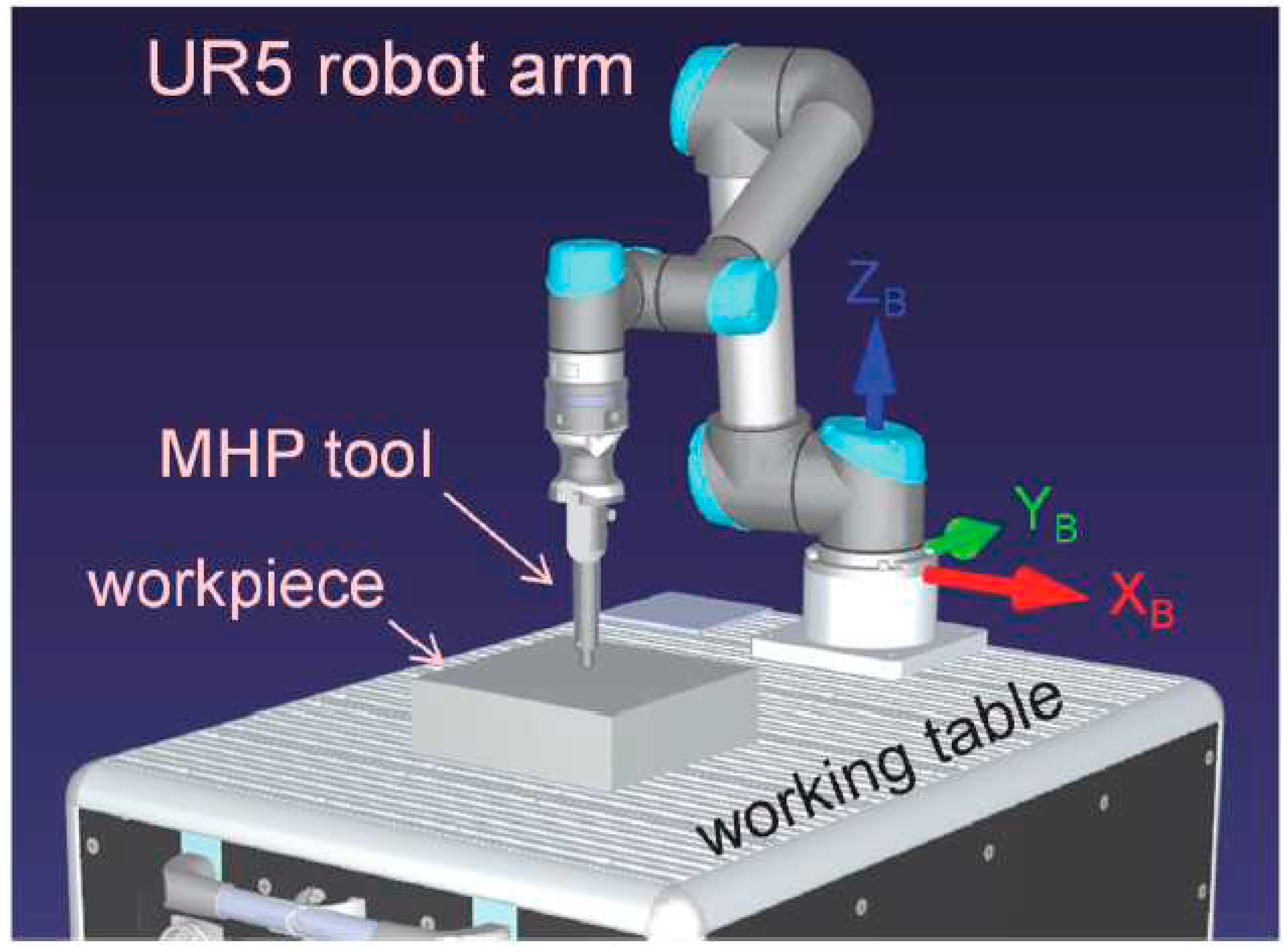
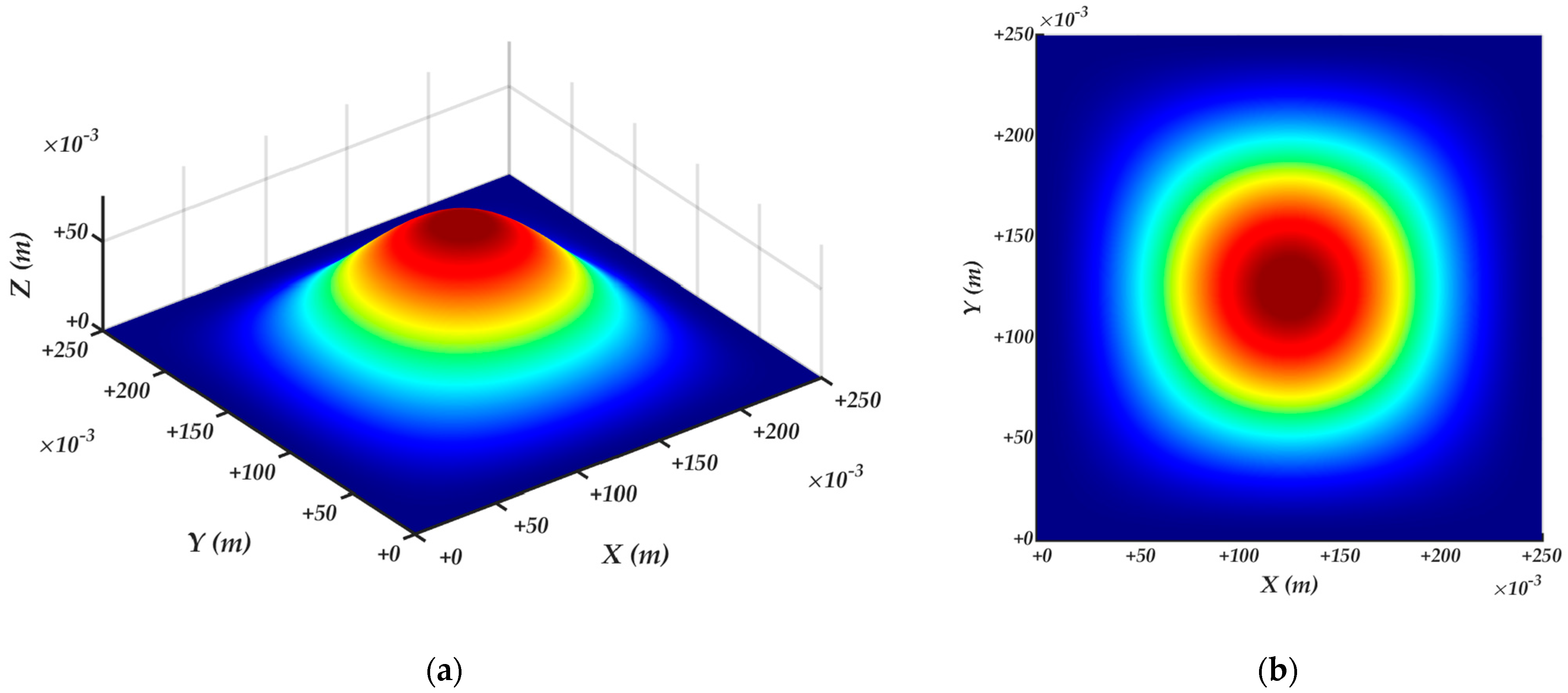
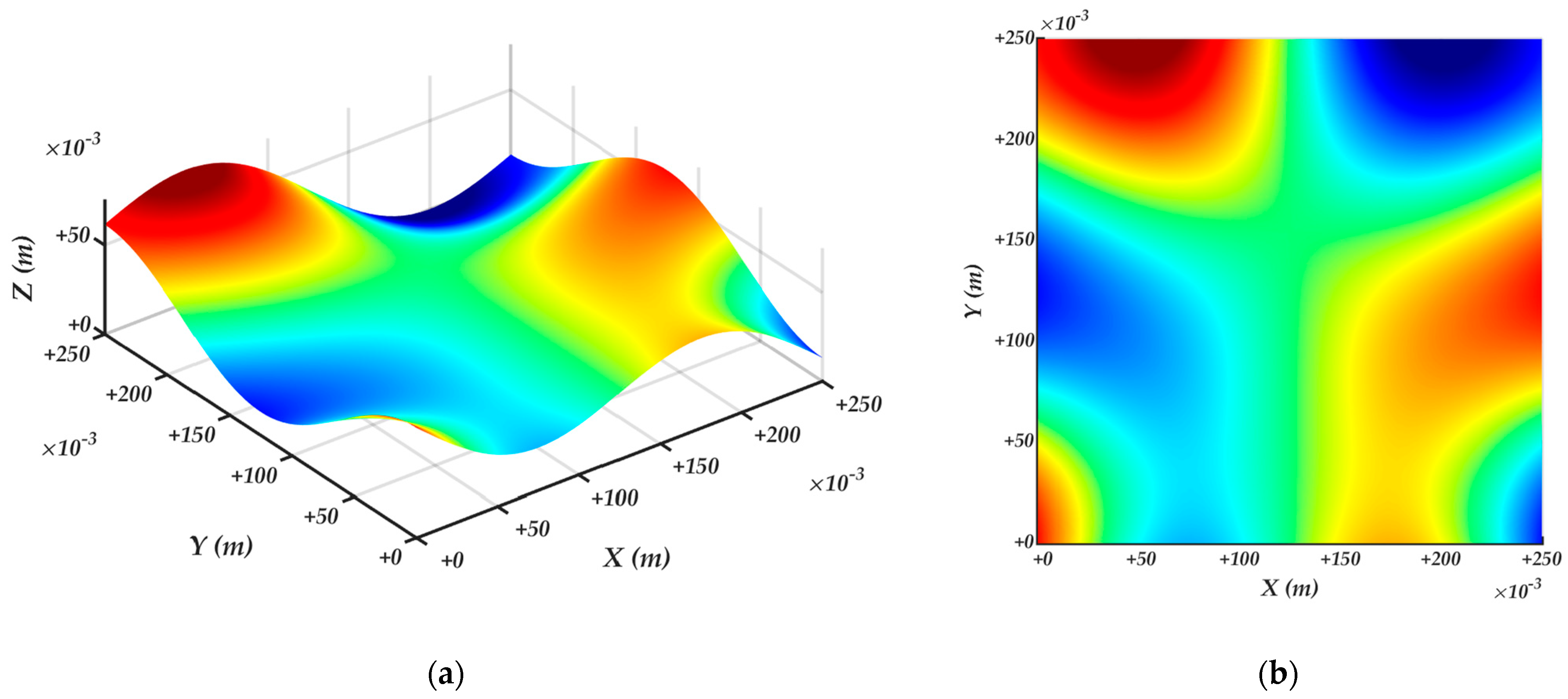
4.1. Experimental setup
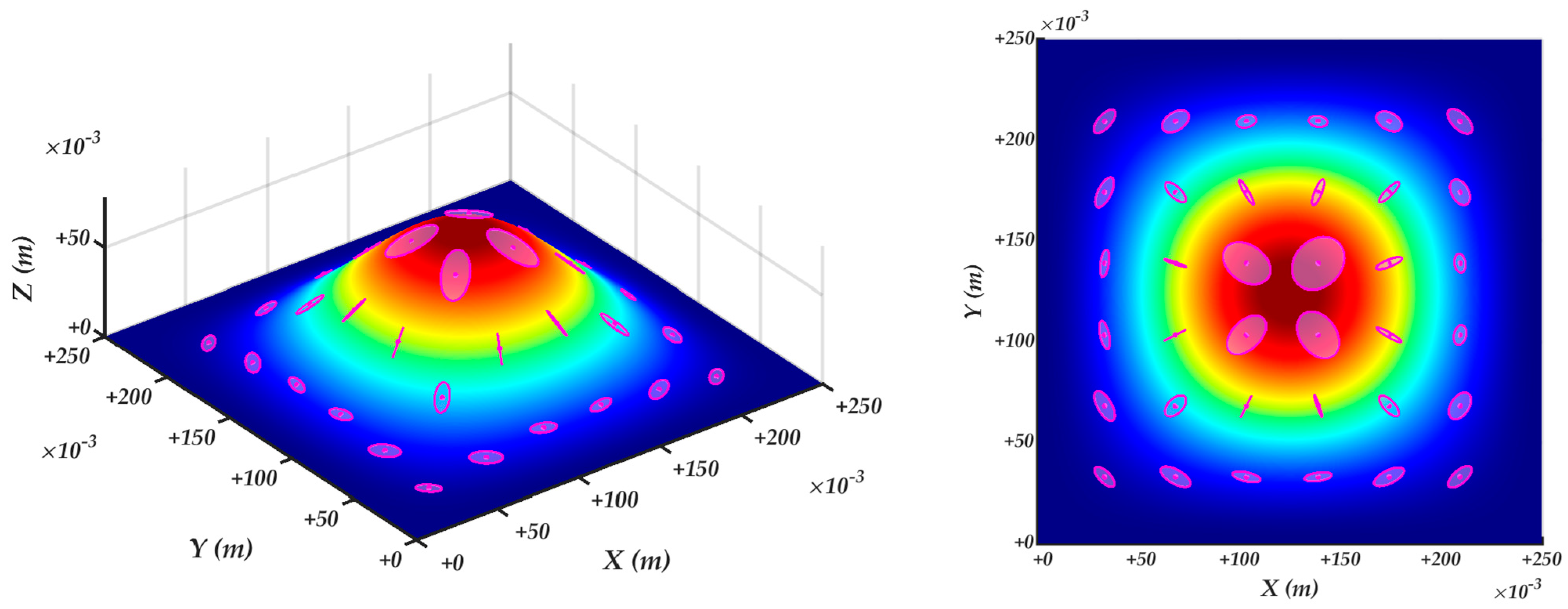
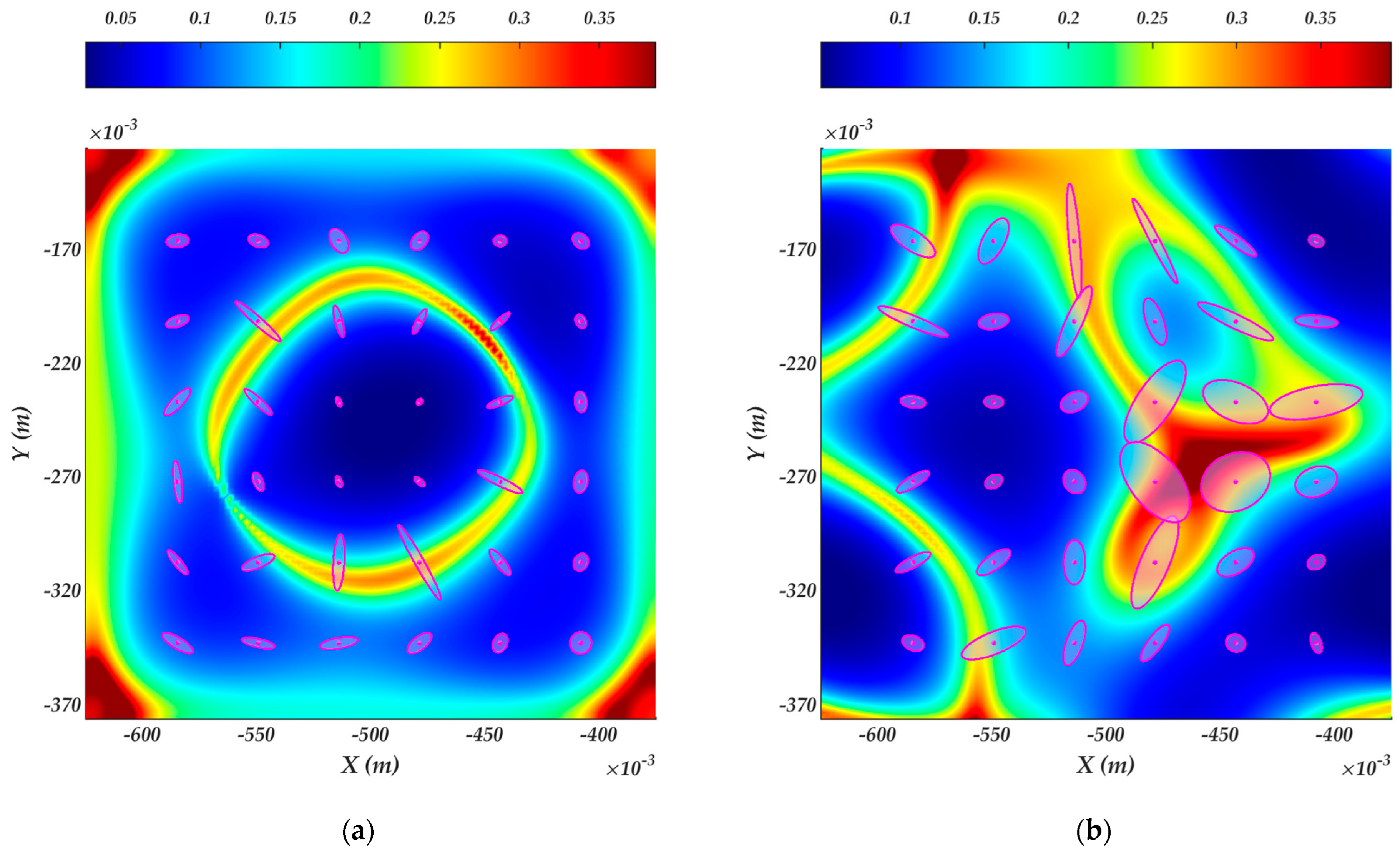
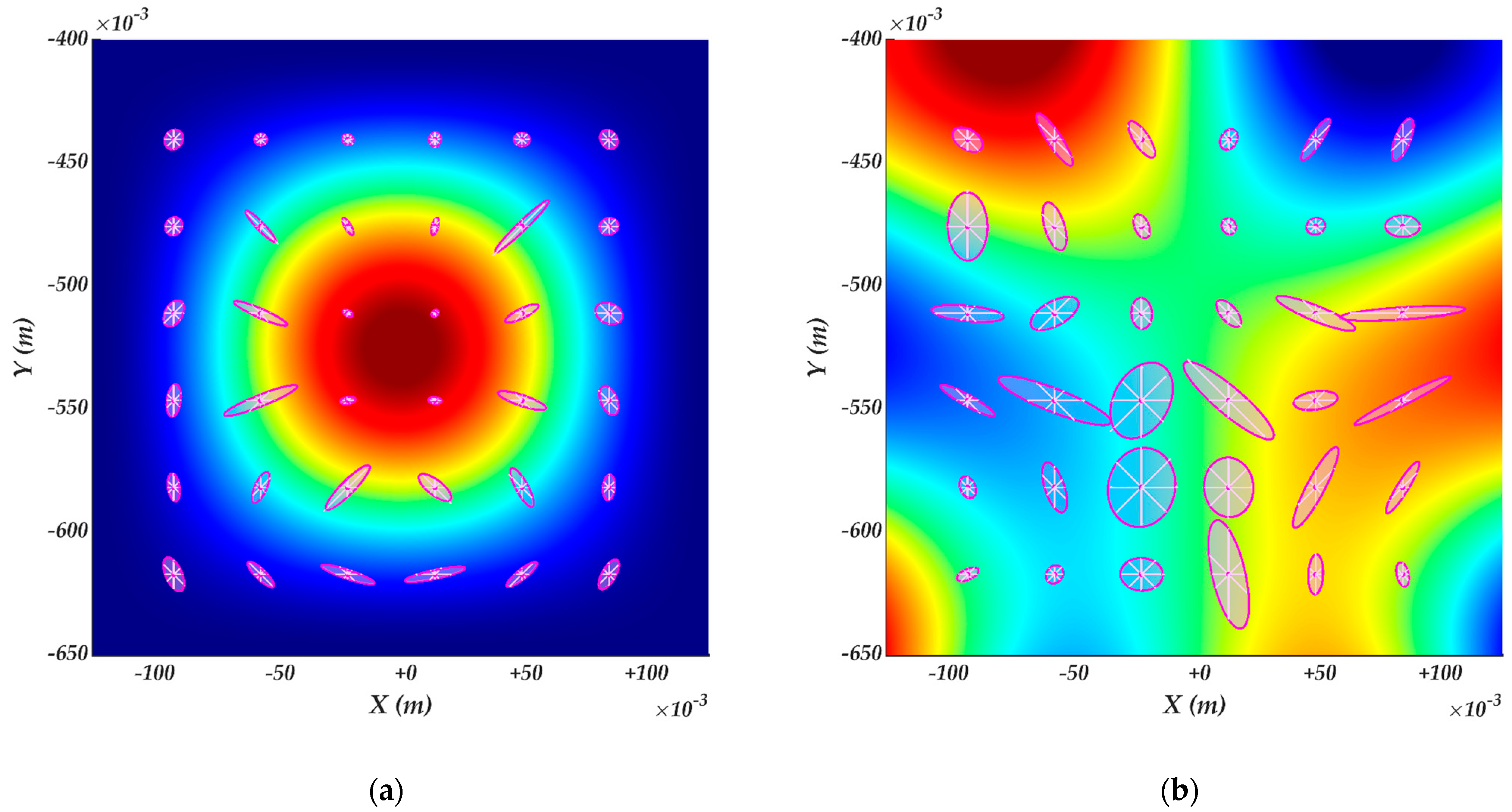
4.2. Surface velocity ellipsoids
4.3. Robot manipulability ellipsoids of the constrained kinematics
5. Conclusions
Funding
Conflicts of Interest
References
- International Federation of Robotics: World Robotics Industrial Robots. Available online: https://ifr.org/worldrobotics (accessed on August 8th, 2023).
- Magrini, E.; Ferraguti, F.; Ronga, A.J.; Pini, F.; De Luca, A.; Leali, F. Human-robot coexistence and interaction in open industrial cells. Robotics and Computer-Integrated Manufacturing 2020, 61, 101846. [Google Scholar] [CrossRef]
- Taesi, C.; Aggogeri, F.; Pellegrini, N. COBOT Applications: Recent Advances and Challenges. Robotics 2023, 12. [Google Scholar] [CrossRef]
- Gajšek, B.; Stradovnik, S.; Hace, A. Sustainable Move towards Flexible, Robotic, Human-Involving Workplace. Sustainability 2020, 12. [Google Scholar] [CrossRef]
- Weidemann, C.; Mandischer, N.; van Kerkom, F.; Corves, B.; Hüsing, M.; Kraus, T.; Garus, C. Literature Review on Recent Trends and Perspectives of Collaborative Robotics in Work 4.0. Robotics 2023, 12. [Google Scholar] [CrossRef]
- Aivaliotis, P.; Aivaliotis, S.; Gkournelos, C.; Kokkalis, K.; Michalos, G.; Makris, S. Power and force limiting on industrial robots for human-robot collaboration. Robotics and Computer-Integrated Manufacturing 2019, 59, 346–360. [Google Scholar] [CrossRef]
- Ji, W.; Wang, L. Industrial robotic machining: a review. The International Journal of Advanced Manufacturing Technology 2019, 103, 1239–1255. [Google Scholar] [CrossRef]
- Qu, X.; Wan, M.; Shen, C.-J.; Zhang, W.-H. Profile error-oriented optimization of the feed direction and posture of the end-effector in robotic free-form milling. Robotics and Computer-Integrated Manufacturing 2023, 83, 102580. [Google Scholar] [CrossRef]
- Onstein, I.F.; Bjerkeng, M.; Martinsen, K. Automated Tool Trajectory Generation for Robotized Deburring of Cast Parts Based on 3D Scans. Procedia CIRP 2023, 118, 507–512. [Google Scholar] [CrossRef]
- Bogue, R. Finishing robots: a review of technologies and applications. Industrial Robot: An International Journal 2009, 36, 6–12. [Google Scholar] [CrossRef]
- Yang, J.; Chen, H.; Qi, R.; Ding, H.; Yin, Y. A novel approach to robotic grinding guaranteeing profile accuracy using rigid-flexible coupling force control for free-formed surfaces. CIRP Annals 2023, 72, 313–316. [Google Scholar] [CrossRef]
- Kharidege, A.; Ting, D.T.; Yajun, Z. A practical approach for automated polishing system of free-form surface path generation based on industrial arm robot. The International Journal of Advanced Manufacturing Technology 2017, 93, 3921–3934. [Google Scholar] [CrossRef]
- Ke, X.; Yu, Y.; Li, K.; Wang, T.; Zhong, B.; Wang, Z.; Kong, L.; Guo, J.; Huang, L.; Idir, M.; et al. Review on robot-assisted polishing: Status and future trends. Robotics and Computer-Integrated Manufacturing 2023, 80, 102482. [Google Scholar] [CrossRef]
- Bleicher, F.; Lechner, C.; Habersohn, C.; Kozeschnik, E.; Adjassoho, B.; Kaminski, H. Mechanism of surface modification using machine hammer peening technology. CIRP Annals 2012, 61, 375–378. [Google Scholar] [CrossRef]
- Hagen, L.; Baumann, J.; Heidelmann, M.; Biermann, D.; Tillmann, W. Machine Hammer Peening and Its Effect on the Surface Integrity of Arc-Sprayed WC-W2C-FeCMnSi Coatings. Coatings 2023, 13, 1563. [Google Scholar] [CrossRef]
- Schulze, V.; Bleicher, F.; Groche, P.; Guo, Y.B.; Pyun, Y.S. Surface modification by machine hammer peening and burnishing. CIRP Annals 2016, 65, 809–832. [Google Scholar] [CrossRef]
- Hähnel, S.; Pini, F.; Leali, F.; Dambon, O.; Bergs, T.; Bletek, T. Reconfigurable Robotic Solution for Effective Finishing of Complex Surfaces. In Proceedings of the 2018 IEEE 23rd International Conference on Emerging Technologies and Factory Automation (ETFA), 4-7 Sept. 2018; 2018; pp. 1285–1290. [Google Scholar]
- KUKA. Surface processing with a KR QUANTEC and KUKA.CNC. Available online: https://www.kuka.com/en-de/industries/solutions-database/2016/07/solution-robotics-sematek (accessed on 9th August 2023).
- Robotmaster. Offline Programming Software is Single Solution for Robotic Hammer Peening of Automotive Stamping Dies. Available online: https://www.roboticstomorrow.com/article/2017/12/offline-programming-software-is-single-solution-for-robotic-hammer-peening-of-automotive-stamping-dies/11173 (accessed on August 9th, 2023).
- Weingartshofer, T.; Bischof, B.; Meiringer, M.; Hartl-Nesic, C.; Kugi, A. Optimization-based path planning framework for industrial manufacturing processes with complex continuous paths. Robotics and Computer-Integrated Manufacturing 2023, 82, 102516. [Google Scholar] [CrossRef]
- Nektarios, A.; Aspragathos, N.A. Optimal location of a general position and orientation end-effector's path relative to manipulator's base, considering velocity performance. Robotics and Computer-Integrated Manufacturing 2010, 26, 162–173. [Google Scholar] [CrossRef]
- Doan, N.C.N.; Lin, W. Optimal robot placement with consideration of redundancy problem for wrist-partitioned 6R articulated robots. Robotics and Computer-Integrated Manufacturing 2017, 48, 233–242. [Google Scholar] [CrossRef]
- Xia, Y.; Zhao, L.; Liu, Z.; Zhu, K. Optimization of Machining Position for Wheel Hub Polishing Robot Based on the Kinematic Index. In Proceedings of the 2022 8th International Conference on Control, Automation and Robotics (ICCAR), 8-10 April 2022; 2022; pp. 155–160. [Google Scholar]
- Weingartshofer, T.; Hartl-Nesic, C.; Kugi, A. Optimal TCP and Robot Base Placement for a Set of Complex Continuous Paths. In Proceedings of the 2021 IEEE International Conference on Robotics and Automation (ICRA), 30 May-5 June 2021; 2021; pp. 9659–9665. [Google Scholar]
- Malhan, R.K.; Kabir, A.M.; Shah, B.; Gupta, S.K. Identifying Feasible Workpiece Placement with Respect to Redundant Manipulator for Complex Manufacturing Tasks. In Proceedings of the 2019 International Conference on Robotics and Automation (ICRA), 20-24 May 2019; 2019; pp. 5585–5591. [Google Scholar]
- Malhan, R.K.; Shembekar, A.V.; Kabir, A.M.; Bhatt, P.M.; Shah, B.; Zanio, S.; Nutt, S.; Gupta, S.K. Automated planning for robotic layup of composite prepreg. Robotics and Computer-Integrated Manufacturing 2021, 67, 102020. [Google Scholar] [CrossRef]
- Balci, B.; Donovan, J.; Roberts, J.; Corke, P. Optimal Workpiece Placement Based on Robot Reach, Manipulability and Joint Torques. In Proceedings of the 2023 IEEE International Conference on Robotics and Automation (ICRA), 2023, 29 May-2 June 2023; 2023; pp. 12302–12308. [Google Scholar]
- Stradovnik, S.; Hace, A. Task-Oriented Evaluation of the Feasible Kinematic Directional Capabilities for Robot Machining. Sensors 2022, 22. [Google Scholar] [CrossRef]
- Lynch, K.M.; Park, F.C. Modern Robotics: Mechanics, Planning, and Control; Cambridge University Press: 2017.
- Yoshikawa, T. Manipulability of Robotic Mechanisms. International Journal of Robotics Research 1985, 4, 3–9. [Google Scholar] [CrossRef]
- Klein, C.A.; Blaho, B.E. Dexterity Measures for the Design and Control of Kinematically Redundant Manipulators. The International Journal of Robotics Research 1987, 6, 72–83. [Google Scholar] [CrossRef]
- Schwartz, E.; Manseur, R.; Doty, K. Noncommensurate systems in robotics. Int. J. Robot. Automat. 2002, 17, 86–92. [Google Scholar]
- Melchiorri, C.; Chiaccio, P.; Chiaverini, S.; Sciavicco, L.; Siciliano, B. Comments on "Global task space manipulability ellipsoids for multiple-arm systems" and further considerations" [with reply] P. Chiacchio, et al. IEEE Transactions on Robotics and Automation 1993, 9, 232–236. [Google Scholar] [CrossRef]
- Gosselin, C.M. The optimum design of robotic manipulators using dexterity indices. Robotics and Autonomous Systems 1992, 9, 213–226. [Google Scholar] [CrossRef]
- Dubey, R.; Luh, J.Y.S. Redundant robot control using task based performance measures. Journal of Robotic Systems 1988, 5, 409–432. [Google Scholar] [CrossRef]
- Vahrenkamp, N.; Asfour, T.; Metta, G.; Sandini, G.; Dillmann, R. Manipulability analysis. In Proceedings of the 2012 12th IEEE-RAS International Conference on Humanoid Robots (Humanoids 2012), 29 Nov.-1 Dec. 2012; 2012; pp. 568–573. [Google Scholar]
- Chiu, S.L. Task Compatibility of Manipulator Postures. International Journal of Robotics Research 1988, 7, 13–21. [Google Scholar] [CrossRef]
- Wang, Y.; Wang, L. Reactive task-oriented redundancy resolution using constraint-based programming. 2016 IEEE/RSJ International Conference on Intelligent Robots and Systems (IROS) 2016, 5689-5694.
- Doty, K.L.; Melchiorri, C.; Schwartz, E.M.; Bonivento, C. Robot manipulability. IEEE Transactions on Robotics and Automation 1995, 11, 462–468. [Google Scholar] [CrossRef]
- Staffetti, E.; Bruyninckx, H.; De Schutter, J. On the Invariance of Manipulability Indices. In Advances in Robot Kinematics: Theory and Applications, Lenarčič, J., Thomas, F., Eds.; Springer Netherlands: Dordrecht, 2002; pp. 57–66. [Google Scholar]
- Yoshikawa, T. Translational and rotational manipulability of robotic manipulators. In Proceedings of the 1991 International Conference on Industrial Electronics, Control and Instrumentation (IECON '91), 28 Oct.-1 Nov. 1991; 1991; pp. 1170–1175. [Google Scholar]
- Mansouri, I.; Ouali, M. The power manipulability - A new homogeneous performance index of robot manipulators. Robotics and Computer-Integrated Manufacturing 2011, 27, 434–449. [Google Scholar] [CrossRef]
- Mansfeld, N.; Keppler, M.; Haddadin, S. Speed Gain in Elastic Joint Robots: An Energy Conversion-Based Approach. IEEE Robotics and Automation Letters 2021, 6, 4600–4607. [Google Scholar] [CrossRef]
- Kokkinis, T.; Paden, B. Kinetostatic performance limits of cooperating robot manipulators using force-velocity polytopes. Proceedings of the ASME Winter Annual Meeting-Robotics Research 1989, 14. [Google Scholar]
- Lee, J. A study on the manipulability measures for robot manipulators. In Proceedings of the 1997 IEEE/RSJ International Conference on Intelligent Robot and Systems. Innovative Robotics for Real-World Applications. IROS '97, Grenoble, France, 7-11 Sept. 1997; 1997; pp. 1458–1465. [Google Scholar]
- Finotello, R.; Grasso, T.; Rossi, G.; Terribile, A. Computation of kinetostatic performances of robot manipulators with polytopes. In Proceedings of the Proceedings. 1998 IEEE International Conference on Robotics and Automation (Cat. No.98CH36146), 20-20 May 1998; 1998; vol. 3244, pp. 3241–3246. [Google Scholar]
- Long, P.; Padir, T. Evaluating Robot Manipulability in Constrained Environments by Velocity Polytope Reduction. In Proceedings of the 2018 IEEE-RAS 18th International Conference on Humanoid Robots (Humanoids), 6-9 Nov. 2018; 2018; pp. 1–9. [Google Scholar]
- Long, P.; Padir, T. Constrained Manipulability for Humanoid Robots Using Velocity Polytopes. International Journal of Humanoid Robotics 2019, 17. [Google Scholar] [CrossRef]
- Kang, L.; Kim, S.H.; Kim, W.; Yi, B.J. Review of Dimension Inhomogeneity in Robotics. In Proceedings of the 2019 16th International Conference on Ubiquitous Robots (UR), 24-27 June 2019; 2019; pp. 143–148. [Google Scholar]
- Patrikalakis, N.M.; Maekawa, T. Shape Interrogation for Computer Aided Design and Manufacturing; Springer Berlin, Heidelberg: 2002.
- Kobayashi, S. Differential Geometry of Curves and Surfaces; Springer Singapore: 2019.
- Hertrich-Jeromin, U. Differential Geometry (Lecture Notes). 2019.
- Strang, G. Introduction to Linear Algebra, Fifth ed.; Wellesley - Cambridge Press: 2016.
- Nakamura, Y. Advanced Robotics: Redundancy and Optimization; Addison-Wesley: 1991.
- Patel, S.; Sobh, T. Manipulator Performance Measures - A Comprehensive Literature Survey. J Intell Robot Syst 2014, 77, 1–24. [Google Scholar] [CrossRef]
- Baksalary, J.K.; Baksalary, O.M. Particular formulae for the Moore–Penrose inverse of a columnwise partitioned matrix. Linear Algebra and its Applications 2007, 421, 16–23. [Google Scholar] [CrossRef]
- Baksalary, O.M.; Trenkler, G. On formulae for the Moore–Penrose inverse of a columnwise partitioned matrix. Applied Mathematics and Computation 2021, 403, 125913. [Google Scholar] [CrossRef]
- Moulianitis, V.; Katrantzis, E.; Stravopodis, N.; Aspragathos, N. A Comparative Study of Three Manipulator Performance Measures; 2018; pp. 19-27.
- Maciejewski, A.A.; Klein, C.A. Obstacle Avoidance for Kinematically Redundant Manipulators in Dynamically Varying Environments. The International Journal of Robotics Research 1985, 4, 109–117. [Google Scholar] [CrossRef]
- Piziak, R.; Odell, P.L. Matrix Theory - From Generalized Inverses to Jordan Form, 1st ed.; Chapman & Hall/CRC: Boca Raton, FL USA, 2007. [Google Scholar]
- MathWorks: MATLAB. Available online: https://ch.mathworks.com/products/matlab.html (accessed on November 15th, 2023).
- Universal Robots: DH parameters for calculations of kinematics and dynamics. Available online: https://www.universal-robots.com/articles/ur/application-installation/dh-parameters-for-calculations-of-kinematics-and-dynamics/ (accessed on November 15th, 2023).
Disclaimer/Publisher’s Note: The statements, opinions and data contained in all publications are solely those of the individual author(s) and contributor(s) and not of MDPI and/or the editor(s). MDPI and/or the editor(s) disclaim responsibility for any injury to people or property resulting from any ideas, methods, instructions or products referred to in the content. |
© 2023 by the authors. Licensee MDPI, Basel, Switzerland. This article is an open access article distributed under the terms and conditions of the Creative Commons Attribution (CC BY) license (http://creativecommons.org/licenses/by/4.0/).


