1. Introduction
Prior to actual deployment, a new module is required to pass through rigorous tests and modifications in a simulated environment. The process of testing and modification of the new module continues sequentially until the required level of validity is reached. Such virtual environment based development of modules leverages the labor and financial costs as well as risky trial-and-error physical experiments. As a result, in almost all sectors dealing with software development, the implementation of SITL simulation is essential [
1,
2,
3,
4,
5,
6,
7].
SITL substantially saves Money, Energy, and Time [
8,
9]. In running the entire software system on just one computer enables researchers not to wait for the purchase, maintenance, or assembly of actual hardware products. Any software bug does not cause life loss or property damage. When it comes to energy saving, software developers often requires repetitive work of testing and modifying the software under development. Attempting to test and modify the software on actual platform such as UAV and unmanned ground vehicle would be very tedious and unsafe. Moreover, such repetitive process of testing and modifying the software on actual hardware consumes lots of time. The SITL method handles and speeds up complex software development and verification process.
As there are plenty of advantages in utilizing SITL method in custom module development, there are drawbacks when it comes to the effectiveness of the module as it runs on actual hardware. In SITL, the module is processed with simulated time pace which often is not real-time [
10,
11]. The background operating system of a computer used for SITL is not a real-time operating system unlike the operating system used on actual hardware of either UAV or self-driving car. As a result there can be delays or loss of information while the custom module is processed on actual hardware and that deteriorates the performance of the module. In addition to these, module development in SITL is based on linearized dynamic model of actual platform (e.g., UAV model) and acquired data from modeled sensors in SITL are smoother than the data from actual sensors. All theses accounts for the reduced performance of the custom module on actual hardware.
In aerospace sector, the role of SITL simulation tools for the development of new modules for aerial vehicle control is essential. Furthermore, implementing SITL simulation tools for the development of modules of UAVs is by far crucial as these vehicles are often autonomously piloted by unmanned control systems. Many of UAV accidents recorded over years reveal that they are as a result of flight system errors [
12]. Nowadays, UAVs are being deployed for missions such as package delivery, disaster monitoring, and law enforcement in urban areas. This dictates that an in-depth SITL simulation based testing and modification of modules prior to their implementation are indispensable to avoid potential dangers of operational failures.
In order for the modules to be properly developed and tested, the SITL simulation tool, in use, has to be reliably re-designed with unique features of a vehicle model for which the modules are being developed in the simulation process. Shoaib and Mana [
13] designed model specific SITL simulation framework to develop and test a hybrid control algorithm dedicated to their hybrid aircraft. Khoa et al. [
14] designed an SITL configuration to validate the performance effectiveness of their new hybrid UAV model. They also demonstrated the required processes to customize PX4 SITL for the development of vision algorithm for custom UAV model incorporated to the SITL simulation process. A new approach to configuring SITL for flight guidance algorithm development was proposed by Adriano et al. [
15].
There are various SITL simulation tools many of which are provided with flight control firmware. Of these firmware which provide SITL tools, PX4: an open source autopilot firmware is popular for its versatility to run on various hardware and to provide wide range of options for users to customize the firmware with new features. A comprehensive report on the robustness of this firmware was presented by Meier et. al. [
16]. The firmware also comes with multiple aerial, ground, and underground vehicle models that can be suitably used in SITL simulation environment.
Moreover, the architecture of PX4 firmware is modular in that users can implement custom modules without affecting the original firmware. It, also, enables integration of various external hardware (e.g., sensors) and software (e.g., simulators) so as to make the firmware robust. PX4 SITL supports various simulators where Gazebo, flight gear, and jMAVSim are the commonly used ones. The fidelity and versatility of these simulators are determined by factors such as the physics engines that is used to simulate the kinematics and dynamics of a body, stable in simulation process, good visual rendering, and related features [
17,
18]. Pitonakova et. al. [
19] listed out some of these features to compare the performance of simulators. A detailed comparison on some popular simulators was, also, given by Marian et. al. [
20] based on features such as speed and stability during simulation as well as hardware utilization.
The remaining of this work is organized as follows. In
section 2, opportunities and challenges of SITL simulation tools and approaches to resolve the challenges are presented. The necessary technical approaches to incorporate custom modules and models into PX4 SITL are described in
section 3. A case study on effects of model specific parameters on the development and testing of custom module in PX4 SITL are presented in
section 4. In
section 5, results and discussions on the simulation outcomes are presented and conclusions on the relevance of this work are drawn in
section 6.
2. Problem Statement and Methodology
It is of interest to both complete novices and practitioners to test and modify modules in SITL simulation environment prior to their actual implementation. A simulation framework presented by PX4 SITL and Gazebo virtual environment is among the top rated tools used for custom module development in the realm of unmanned aerial system in particular.
The reliability of custom module being developed in a virtual environment is arguable as it may not perform to the extent of its anticipated performance in a real world. As a result a number of approaches are taken to enhance the fidelity of the module where model-based approach is one of them. PX4 SITL is already integrated to Gazebo simulator in which various aerial, ground, and underground vehicle models are incorporated. Active developers of PX4 autopilot are well aware that there can be cases when custom model is required to be added to the pre-existing ones to develop and test model specific modules. Therefore, the PX4 autopilot firmware is developed with a feature that allows users to add custom models and modules. However, there is no complete technical documentation on the customization of PX4 SITL and Gazebo simulator as a single integral entity. A change made in either of the two affects the other. As a result simulation process may abort or output inaccurate values. Thus, the design of realistic SITL simulation tool requires proper configuration and customization of both software.
There are many researchers requesting for technical procedures to resolve their problem [
21,
22,
23,
24]. Most of the technical issues are related to PX4 SITL customization with new models and modules [
25,
26,
27,
28,
29,
30,
31]. Likewise, Gazebo simulator invokes issues if not properly customized. There are multiple questions raised in Gazebo discussion forums as well [
32,
33,
34,
35]. Though issues of the two software customization are addressed through discussion forums, still there are many more left open. Even, those which are addressed are available here-and-there in a way that they are time-costly to get into and to comprehend. Questions posted on discussion forums often do not get replies in days or even in months.
The time spent by researchers in searching for fragmented solutions could have helped the researchers to focus on their respective research problem. Therefore, it is essential that the already addressed ones are presented in a synchronized way and those left open be addressed accordingly. Therefore, this paper presents technical procedures to be followed to successfully customize both PX4 SITL and Gazebo simulator.
Following the technical presentations, a case study is conducted to verify the essence of proper customization of SITL simulation tool for development of reliable custom modules. In the process of investigating the effects of model specific parameters on the development and testing of a custom module, parameters such as mass, moments of inertia, and aerodynamic are used. The mechanism is designed in such a way that accurate and inaccurate values of the parameters are incorporated in the simulation process and the outputs are analyzed.
3. PX4 Autopilot
PX4 (PX stands for Pixhawk and 4 refers to the fourth round re-writing of the firmware) is an autopilot firmware for unmanned vehicles. It is an open source available for off-the-shelf implementation by end-users or customization by researchers. The PX4 firmware is a cross-platform that enables personal computers run the firmware in a simulated environment. This flight control firmware is actively being developed in various sectors all the way from universities to industries. The firmware can run on any operating system that provides portable operating system interface (POSIX): a standard made suitable for users to port their software across platforms. Operating systems such as Nuttx, Linux, Windows, and MacOS provide POSIX, hence, PX4 can run on any of these operating systems though the use of Linux is highly recommended. The PX4 firmware customization presented in this work runs on Linux operating system.
The PX4 autopilot firmware is preferred by researchers and commercial sectors for it is under Berkeley software distribution (BSD) licensing that allows everyone to customize the firmware without publicizing the customized source codes and to commercialize with or without modification. Three of the most important features of this autopilot firmware are:
- ⊙
modularity: A user can replace, modify, or add new modules without affecting the integrity of the firmware. Researchers take advantage of this feature and customize the firmware easily.
- ⊙
large number of peripherals: many external hardware such as distance sensors, IMU sensors, LiDARs, GPS and, optical flow are supported. It is also possible to add custom driver module to the firmware so as to support a new hardware.
- ⊙
availability of many airframe types: the firmware is rich in the number of airframe types it supports. However, it is still open for a user to add any custom airframe type.
3.1. Architecture
PX4 firmware contains two layers: the applications layer commonly known as flight stack and communication service layer known as middleware. The flight stack layer deals with estimation (eg. position and attitude), control, navigation and guidance whereas the middleware provides inter-applications and inter-hardware communication services. It is through the middleware that the PX4 firmware provides its SITL version for researchers to develop their algorithms in simulated environment. The middleware layer also enables communication between the firmware and the operating system it is running on. Communications among applications are handled by the so called micro object request broker (uORB) of the middleware. This uORB allows modules to publish their outputs and/or subscribe to outputs of other modules asynchronously. The outputs are messaged through topics (message buses). These topics are listed in the directory: ~, where PX4-Autopilot is the root directory of PX4 firmware to which a user navigates to build and upload the firmware. Note that, the guidelines given in this paper is based on PX4 firmware version 1.9.2 stable release. There can be some modifications and re-locations of directories in the other versions of the firmware.
3.2. PX4 SITL
PX4 firmware provides SITL feature that is made suitable for computer based simulation of algorithms under development. PX4 SITL uses two modules: simulator and mavlink to communicate with the external environments. The two modules are located in: ~ directory. The simulator module communicates with virtual environment such as Gazebo simulator whereas the mavlink module communicates with ground control station (e.g., QGroundcontrol), and offboard/APIs or companion computers. Both mavlink and simulator modules receive information from external environments and send to uORB so that other PX4 modules take these information for use. Likewise, information published by PX4 modules to uORB topics are delivered to external environments through mavlink and simulator modules. It is possible that PX4 SITL and the external environments run either on the same computer or different computers. In either cases, PX4 mavlink defines ports as local and remote where local ports are ports to which PX4 SITL listens and remote ports are ports to which information is broadcasted. The local and remote ports are specified by the startup file rcS located in: ~.
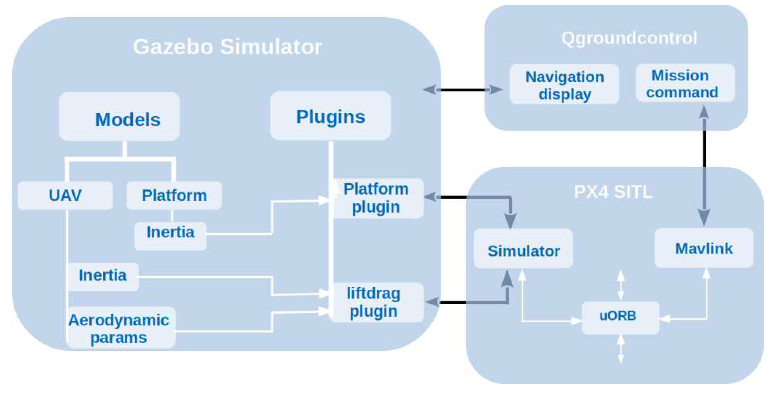
Communication between Gazebo simulator and PX4 SITL begins as the simulator sends sensors’ data through gazebo plugin to a defined UDP port. PX4 SITL listens to the port and acquire sensors’ data through its Simulator model. When QGroundcontrol is opened while SITL simulation process is active, it communicates not only with PX4 SITL but also with Gazebo simulator. QGroundcontrol gets connected to Gazebo simulator as QGroundcontrol initiates communication with simulator by sending message whose destination (dst) is a defined UDP port and expecting for information on a defined source(src) port. Soon the simulator confirms acceptance of message on the src port, it starts sending messages on the dst UDP port. The block diagram of the overall inter-connection among the three software tools are shown in
Figure 1.
3.3. Custom Module in PX4 SITL
Custom modules can be directly included to PX4 firmware. The custom module inclusion to PX4 firmware should fulfill the firmware’s module content and configuration requirements. The firmware has two layers, hence, the type of the custom module written by a user can be categorized to either of these two layers. If the custom module belongs to flight stack, it is saved in ~ and if it belongs to middleware, it is saved either in
- ▹
the drivers directory: as device module, ~,
- ▹
the systemcmds directory: as system module ~, or
- ▹
the lib directory: as shard library module ~
To create a custom module that belongs to flight stack layer and implement it for PX4 SITL simulation process, the following steps are required:
- ▹
create a folder in modules directory located in ~ and name it. The created folder shall contain at least three files: the source code, the header file that enables access to PX4 libraries and the CMakeLists.txt file that introduces the module to the firmeware during compilation.
- ▹
create the header file for the source code and save it in the folder.
- ▹
create a source code and save it in the folder. The content of source code has to follow the publish/subscribe messaging protocol of PX4 firmware. This can be referred from pre-existing source codes.
- ▿
-
copy and paste a CMakeList.txt file from any pre-existing flight stack module and modify its contents. CMakeLists.txt file, mainly, contains
- ⊙
module category specifier: to which the module belongs,
- ⊙
name of the custom module,
- ⊙
name of the main function of the source code, and
- ⊙
name of the source code.
- ▿
-
Once the module creation is completed, the module has to be configured with PX4 firmware. For this, there are two things to consider:
- ⊙
to test the custom module in SITL, list the name of the custom module in the default.cmake file located in ~. The name of the custom module should be listed under the category which was specified in CMakeLists.txt file of the custom module and
- ⊙
-
to upload the custom module to flight control board, add it to default.cmake file located in.
~[version of flight control board. e.g., fmu-v5]
Make sure that the name of the custom module is added to the default.cmake in the right category.
- ⊙
The custom module is then build along with other modules when a build command is prompted.
3.3.1. Start/Stop custom module
During SITL simulation tests, the custom module can be started or stopped on the SITL shell (pxh). Furthermore, custom module can be automatically started upon autopilot boot if the module is included to one of the startup shell scripts located in ~. To be more specific, the custom module has to be included to the appropriate startup shell script. For instance, if the custom module is specific to:
- ▹
multicopter UAV, include the custom module in rc.mc_apps.
- ▹
VTOL UAV, include the custom module in rc.vtol_apps.
This starts the custom module only if the required airframe is used. Detailed explanation on the sequence of startup shell scripts can be found in
here.
3.3.2. Simulation results
SITL simulation results are stored in .ulg file format. The location of these data depends on the option taken to launch PX4 sitl.
- ▹
If the model is launched using , the simulation data are store in the log directory located in: ~.
- ▹
If the model is launched using roslaunch (e.g., px4 mavros_posix_sitl.launch), the simulation data are stored in log file located in: ~.
In order to get access to the numerical data of .ulg file, the python script named pyulog can be used. The installation instructions are given in
pyulog. The command:
generates excel file from the .ulg file. The .ulg can, also, be directly plotted using
PX4 flight review.
3.4. Gazebo 3D Simulation Environment
Gazebo is an open source software that provides a virtual three-dimensional world for researchers to rigorously test algorithms and models before implementing them for real missions. The software has modular architecture like that of PX4 firmware. It has a close to realistic physics engines that accurately and efficiently simulate the kinematics and dynamics of 3D models and is among well known powerful simulation tools used by many sectors dealing with autonomous vehicles [
36,
37].
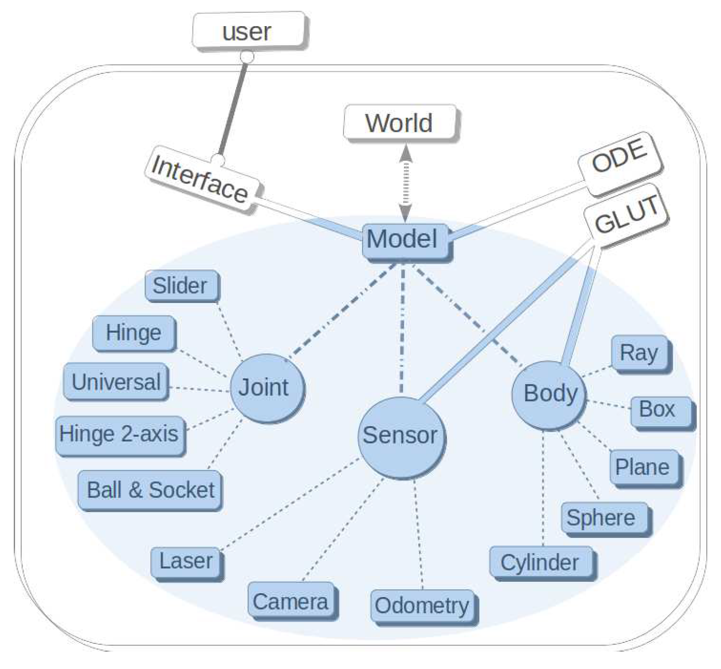
Gazebo presents a 3D virtual world and model(s) being simulated in the world. As shown in
Figure 2, a client interacts with the model(s) through Gazebo APIs.
The word "Model" in Gazebo refers to visual representation of an object that may constitute rigid bodies (links) and joints between the links. It is also possible that a model has one link with no joint. Moreover, a model may include sensor(s) attached to the link(s) or the joint(s). Gazebo implements open dynamic engine (ODE): a physics engine that handles kinematics and dynamics of the model(s) as well as data generation from sensors. Though, not shown in the figure, Gazebo also supports the use of other physics engines: Bullet for gaming, Simbody for biomechanics, and Dynamics Animation & Robtics Toolkits (DART) for computer graphics and robot control. For visual rendering and display of sensors and other objects such as vehicles in a simulated world, Gazebo uses OpenGL and OpenGL Utility Toolkit (GLUT). Gazebo also presents many features of actual world such as gravity, light, wind, water and so on.
3.4.1. Gazebo Plugins
A Gazebo plugin is a code that handles direct access to all functionalities of Gazebo. There are six different plugin types: Model, Sensor, World, Visual, System, and Graphical User Interface (GUI). Gazebo software can be extended by adding custom plugins to it. Gazebo plugins play roles of information interchange between PX4 SITL and Gazebo simulation environment. PX4 SITL_gazebo has plugins located in: ~. However, when custom model is introduced to Gazebo, the model may require a new plugin. To create a custom Gazebo plugin, it is recommended to copy the already existing plugin of the same type. If the custom plugin is for model, then copy already existing model plugin and modify as per requirements. If the custom plugin is for video streaming, the existing GUI plugin type is to be copied.
Upon compiling the custom plugin, corresponding shared library is generated and stored in: ~. This library can be called into Gazebo vehicle model to control model properties such as dynamics of joints of the vehicle model. As the name indicates, model plugin is used by Gazebo models, sensor plugin is used by sensors, and so on. The technical steps required to create a custom Gazebo plugin are as follows:
- ▹
-
write and save the header file of the source code in:
~.
The header calls in required Gazebo functions and contains the class that inherits a plugin type.
- ▹
-
write and save the custom plugin source code in the directory:
~.
For a source code developed from scratch, it is important to make sure that the following are included in the code:
- ⊙
Gazebo namespace,
- ⊙
function that loads physics engines and information about Gazebo vehicle,
- ⊙
Gazebo topics through which messages are published, and
- ⊙
plugin type registration macro that informs Gazebo about the presence of the plugin and its type.
- ▹
to compile the custom plugin source code, the name of the source code should be listed in CMakeList.txt file located in ~.
Once the name of the custom plugin is included in the Gazebo plugins list, upon building the px4 SITL with Gazebo, a corresponding shared library file with extension of .so file is generated and saved in: ~.
The prefix ’lib’ is added to the custom plugin name to indicate that it is a library. This Gazebo plugin library can be called by the custom model or any other model if needed.
3.4.2. PX4 SITL Gazebo Models
There are various simulation environments that work with PX4 SITL among which, Gazebo, jMAVSim, FlightGear, and AirSim are some. Gazebo is the most widely used simulation environment for PX4 SITL [
38,
39,
40,
41,
42]. It supports lock-step feature of PX4 SITL that enables the PX4 SITL and Gazebo to wait on each other during information processing. This feature has many advantages in PX4 SITL simulation and detail on these advantages is
given.
PX4 SITL provides access to implement any model of aerial, ground, or underground vehicle to the simulation environment. However, the intended model has to have certain file format to be used in the simulation environment. It is essential to know how Gazebo reads and understands a model that is going to be simulated in its virtual world. For a model to be simulated in Gazebo world, it has to have the following components
- ▹
link with mass, inertia, collision, and visual attributes,
- ▹
joints between links of the model to which forces or velocity are applied to put the model into dynamics. A joint has axis of translation or rotation along or about which force or torque is applied,
- ▹
Sensors that can be attached to the model through its links or joints, and
- ▹
Gazebo plugin that provides access to Gazebo functionalities such as physics engines.
In PX4 SITL Gazebo vehicle models, it is required that a model directory has to have at least two files: configuration file saved in .config format and eXtensible Markup Language (XML) file saved in SDF format. A Gazebo model plugin uses vehicle model attributes in the SDF file as inputs for Gazebo physics engine to determine the dynamics of the vehicle model in Gazebo world. There can be two sub-directories: meshes and materials in a model directory. The meshes sub-directory contains links (e.g., vehicle model) and the materials sub-directory contains the texture paints of the links and scripts about the links. The steps required to add and configure custom UAV model in PX4 SITL are as follows
- ▹
create a custom model directory in: ~
- ▹
create two files in the custom model directory: configuration and SDF files.
- ▹
copy and paste contents of configuration and SDF files from pre-existing model to the custom model’s configuration and SDF files.
- ▿
-
modify both the configuration and the SDF files as per needs.
- ⊙
in the configuration file, replace the name of SDF attribute by the custom model’s SDF file name .
- ⊙
-
modification of contents in SDF file requires extensive work, such as
- •
replacing the existing model name by the name of the custom model,
- •
adding and scaling the UAV model into the base_link of the SDF file,
- •
adding texture paint to the vehicle model which is optional,
- •
creating joints between the base_link(UAV model) with other links (e.g., sensor platform model),
- •
attach sensors to link(s) or joints(s).
- ▹
add a model plugin required for the custom model
- ▹
the name of the custom model should be included in the sitl_target.cmake file located in: ~ so that it can be compiled
- ▹
-
create airframe file in airframes directory of PX4 located in
~.
The name of the airframe should be unique with its numeric and/or alphabetic parts.
- ▹
add the name of the airframe to CMakeLists.txt file located in the airframes directory.
In the case of actual scenario (not simulation), a new airframe is created and saved in
~ so that the new airframe shows up in ground control station during vehicle setup.
3.4.3. Custom Mixer
Often, custom models incorporated to PX4 SITL requires custom mixer that outputs servo motor control signals. A mixer in PX4 SITL is a script that takes in actuator_control values and mixes them according to the needs depending on the airframe type and its motors’ arrangement. If the airframe type is a custom built, the mixer has to be defined for this airframe and saved in the directory:
~. The procedure of passing actuator control commands through mixer logic to actuator output in Pulse Width Modulated (PWM) signal form is as follows
- ▹
actuator commanding module (e.g., mc_att_control) publishes normalized attitude angles to actuator_control topic located in: ~.
- ▹
a mixer takes in these normalized angular values and mix them accordingly.
- ▹
the pwm_output_sim located in: ~ scales the mixed angular values to required level of PWM signal, often, rage from 900 to 2000 and publish them to actuator_output topic located in: ~ .
- ▹
these outputs are, then, ported to a designated autopilot board ports to actuate motors/servos connected to the ports.
During PX4 SITL simulation with Gazebo, these actuator output values should be sent to a Gazebo vehicle model through a simulator module located in:
~
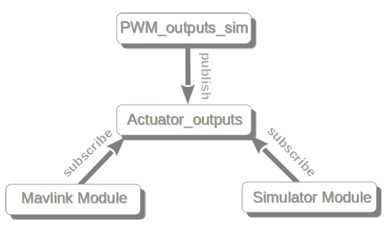
. If the actuator output values are required by a companion computer connected to Pixhawk autopilot board, the values pass through mavlink module located in the above directory. The uORB graph, shown in
Figure 3 demonstrates the flow of PWM signal during PX4 SITL simulation.
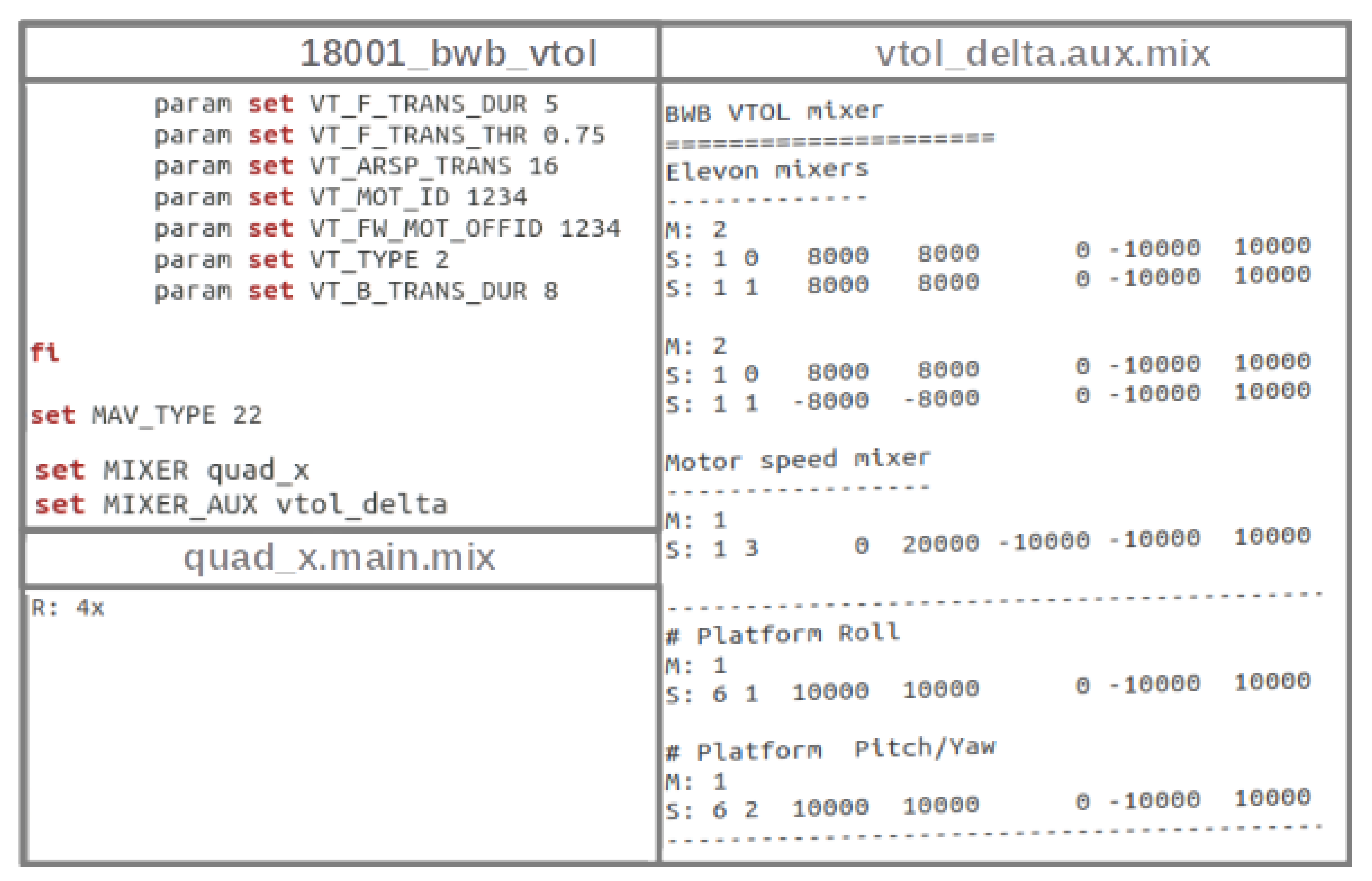
There are two extension option for the mixer file: .main.mix and .aux.mix. The mixer file saved with extension of .main.mix assigns the mixer values to main output ports on flight control board and the file saved with .aux.mix assigns values to auxilary output ports of the board.
Figure 4 shows mixer setup for new airframe type (18001_bwb_vtol) that requires both main and auxilary mixers.
The configuration file of this airframe is created and added to list of configuration files located in:
~. The configuration file, in its content, specifies various parameters specific to the airframe. It, also, contains the mixers defined for the airframe. Both the main and aux mixers of the airframe are specified in the airframe as
- ▹
set MIXER quad_x where quad_x is the main mixer whose content is shown in the second row of left column of
Figure 4.
- ▹
set MIXER_AUX vtol_delta where vtol_delta is for auxilary mixer whose content is shown in the right column of
Figure 4.
add the name of the airframe configuration file in the CMakeLists.txt file of the above directory.
Note that auxilary mixer for sensor gimbal is added to the auxilary mixer of the vtol_delta. The order of mixer blocks defines the PWM output numbering.
3.5. Interfacing Gazebo Vehicle Models with PX4 SITL
A vehicle model in Gazebo world gets access to Gazebo’s functionalities through model plugins that are called into the vehicle model. These model plugins communicate with Gazebo_mavlink_interface_plugin to convey message between Gazebo vehicle model and PX4 SITL. Therefore, PX4 SITL interacts with a Gazebo vehicle model indirectly through gazebo_mavlink_interface_plugin which is located in
~.
The overall flow of information between Gazebo vehicle model and PX4 SITL is shown in
Figure 5
The generated library of gazebo_mavlink_interface_plugin is called in SDF file of Gazebo vehicle model. The plugin contains a control_channels tag in which indexed channel elements are listed with their respective attributes such as
- ▹
joint name of the vehicle model,
- ▹
joint control type, and
- ▹
Gazebo topics through which messages, such as intended positions of joints, are published.
4. Case Study
The case study presented here is to investigate the effects of model specific parameters on the development and testing of a custom module by taking fixed-wing VTOL UAV and steerable sensor platform models as instances. These models are designed and incorporated into the PX4 SITL Gazebo simulation process along with their respective parameters.
The objective of this investigation is to analyze how a custom module under development is affected by faulty values of model parameters. The custom module is intended to control the dynamics of the steerable sensor platform mounted on the nose of a UAV model. It seems that the custom module is dependent only on the sensor platform for which it is being developed but, in this case study, the effects of UAV model parameters are also considered.
For the sake of completeness, the design process of the models and extraction of model specific parameters are presented in detail. The operational modes of the steerable sensor platform whose dynamics is controlled by the custom module are explained. Different flight mission profiles are given to the UAV and the performance of the custom module is tested for missions under accurate and faulty values of parameters of the models.
4.1. UAV Model Design and Analysis
The UAV model is designed in OpenVSP: Vehicle Skitch Pad released by NASA as open source software for public use [
43]. This software tool is parametric and has capability of calculating mass, center of gravity, moments of inertia of the UAV and so on. Moreover, the software is integrated with a module named VSPAERO that analyzes aerodynamic performance of the UAV from which required aerodynamic parameters are extracted.
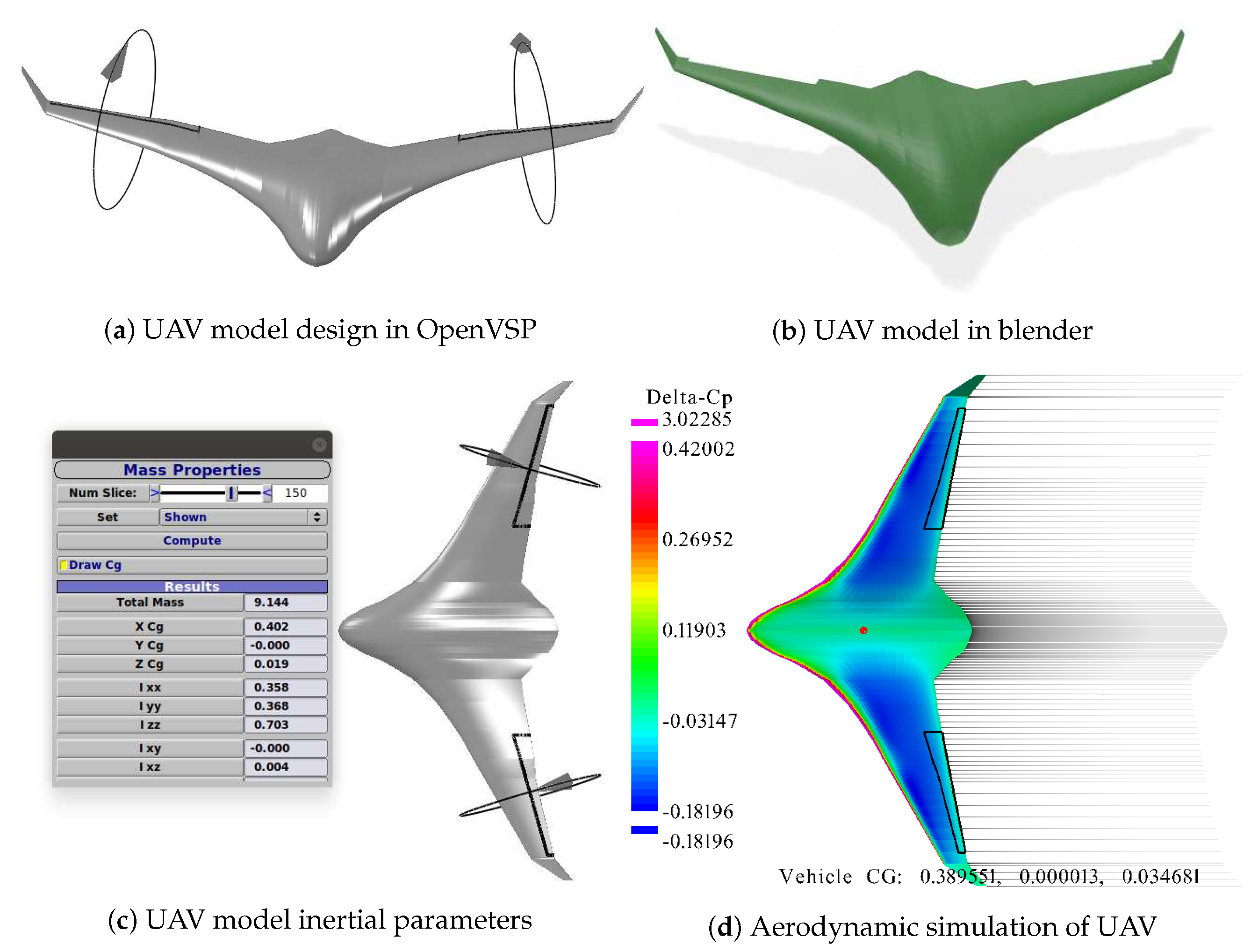
A blended wing-body (BWB) VTOL UAV model, shown in
Figure 6a, is designed as a new model required to be incorporated to PX4 SITL along with model specific parameters. The design of the UAV is in such a way that steerable sensor platform/gimbal can be mounted on its nose. The UAV model is imported to Blender open source software tool to trim the nose and cutout the control surfaces of the UAV as shown in
Figure 6b. In Gazebo simulation environment, the UAV is considered as a link and the control surfaces as another links that are attached to the UAV by revolute joints. Inertial property parameters, shown in
Figure 6c, of the UAV can be extracted from OpenVSP and imported to inertial attributes of SDF file of the UAV model in PX4 SITL Gazebo vehicle model.
Aerodynamic performance of the UAV is analyzed by VSPAERO.
Figure 6d shows span-wise distribution of pressure difference over the wing area and the location of center of gravity of the UAV. Parameters required in PX4 SITL Gazebo vehicle model are identified, as shown in
Table 1, and extracted from the simulation results of VSPAERO. The required parameters are listed as attributes in SDF file of PX4 SITL Gazebo vehicle model. The Gazebo plugin that imports these attributes into Gazebo physics engine is called liftdrag_plugin located in: ~
.
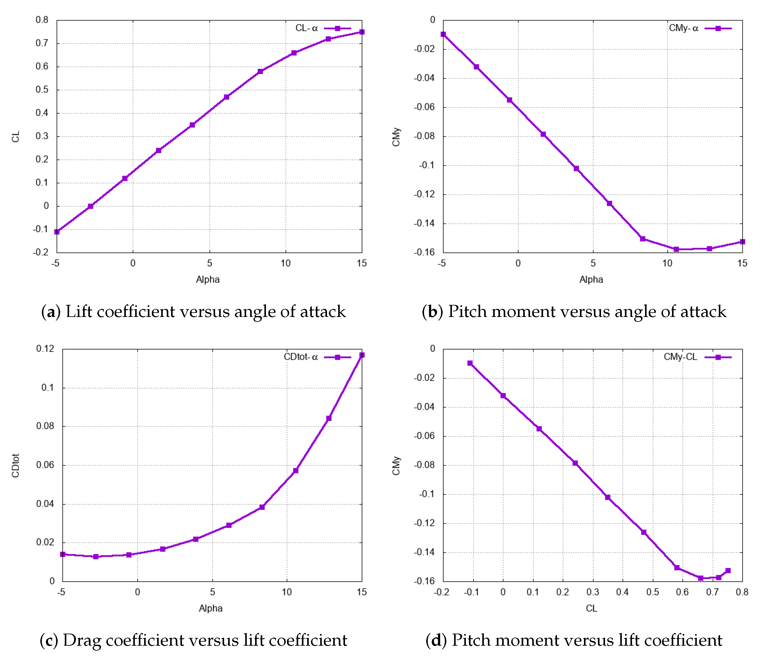
VSPAERO generates the history file that contains the aerodynamic parameters for different flight scenario. Plots of the aerodynamic performance of the UAV model are shown
Figure 7. The required aerodynamic parameters can be obtained directly from the plots or their derivatives (slopes). For the variable "controlJointRadToCL" in
Table 1, VSPAERO runs multiple times to acquire the relationship between the coefficient of lift and radial deflection of control surface. The area of the control surface is directly obtained from OpenVSP.
4.2. Sensor Platform Model Design and Application
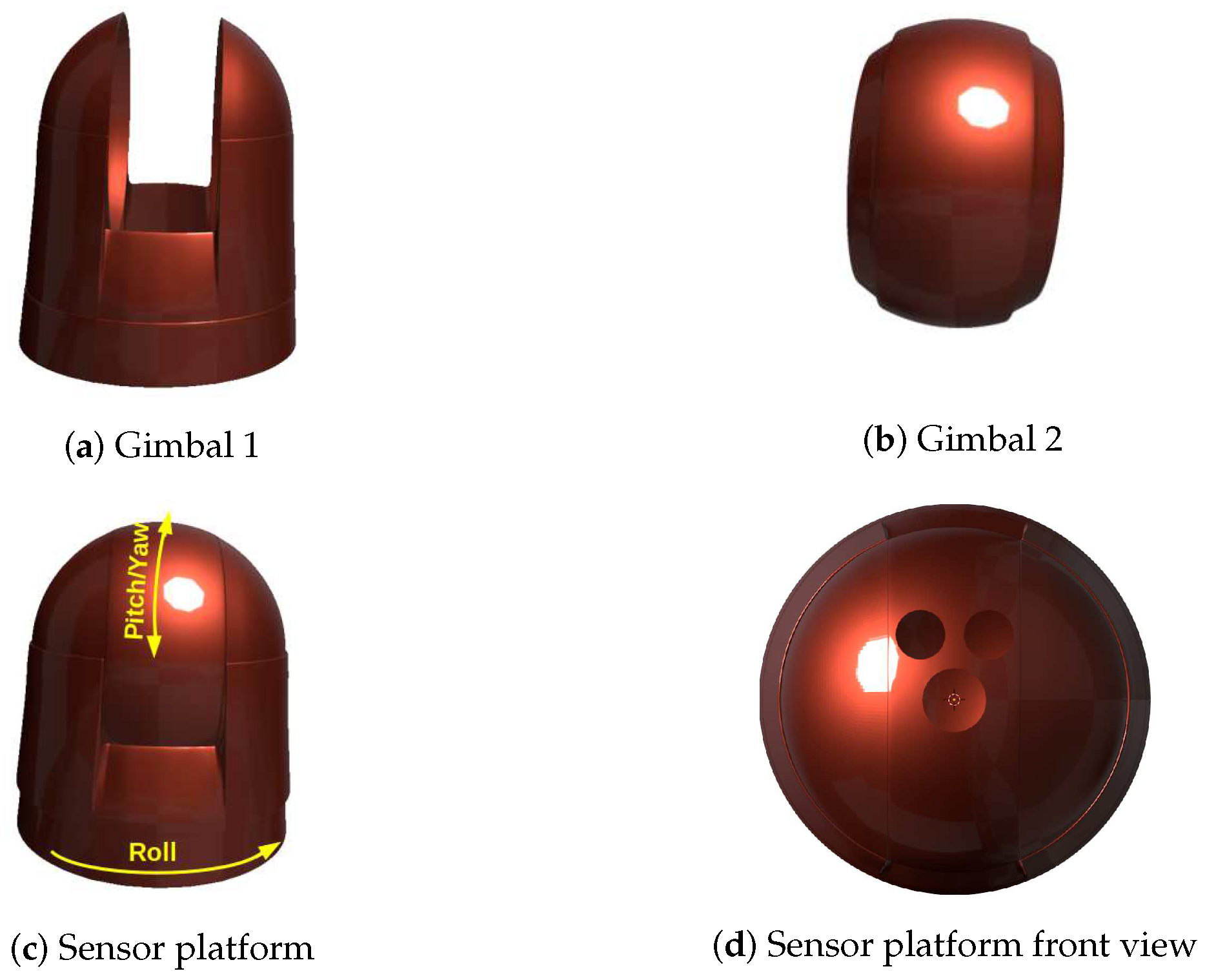
A model of steerable sensor platform, shown in
Figure 8, was created using Blender . The platform is designed to fit into the nose of the BWB VTOL UAV model. To determine its mass and elements of inertial moments, the platform is imported to FreeCAD: an open source software tool. As a result, a mass of 0.75 kg and moments of inertia (
and
) are obtained.
Gimbal 1, shown in
Figure 8a, is the component of the platform that is designed to be connected to the nose of the vehicle model with revolute joint in such a way that it rolls about the forward axis through the nose of the UAV. Gimbal 2, shown in
Figure 8b, is the component of the platform that is connected to the Gimbal 1 with revolute joint in pitch/yaw. The two gimbals are assembled as shown in
Figure 8c and the assembly is termed as sensor platform where sensors are mounted on Gimbal 2. Gimbal 2 of the platform can be designed to carry different sensors according to the requirements. The front view of the sensor platform is shown in
Figure 8d. It is shown in this figure that Gimbal 2 is designed to carry monocular camera in lower section and LiDAR sensor in upper section. The roll of Gimbal 1 about the nose of the UAV and the pitch/yaw of Gimbal 2 about gimbal 1 enables the platform to engage the sensors to all sides of the UAV except rear side.
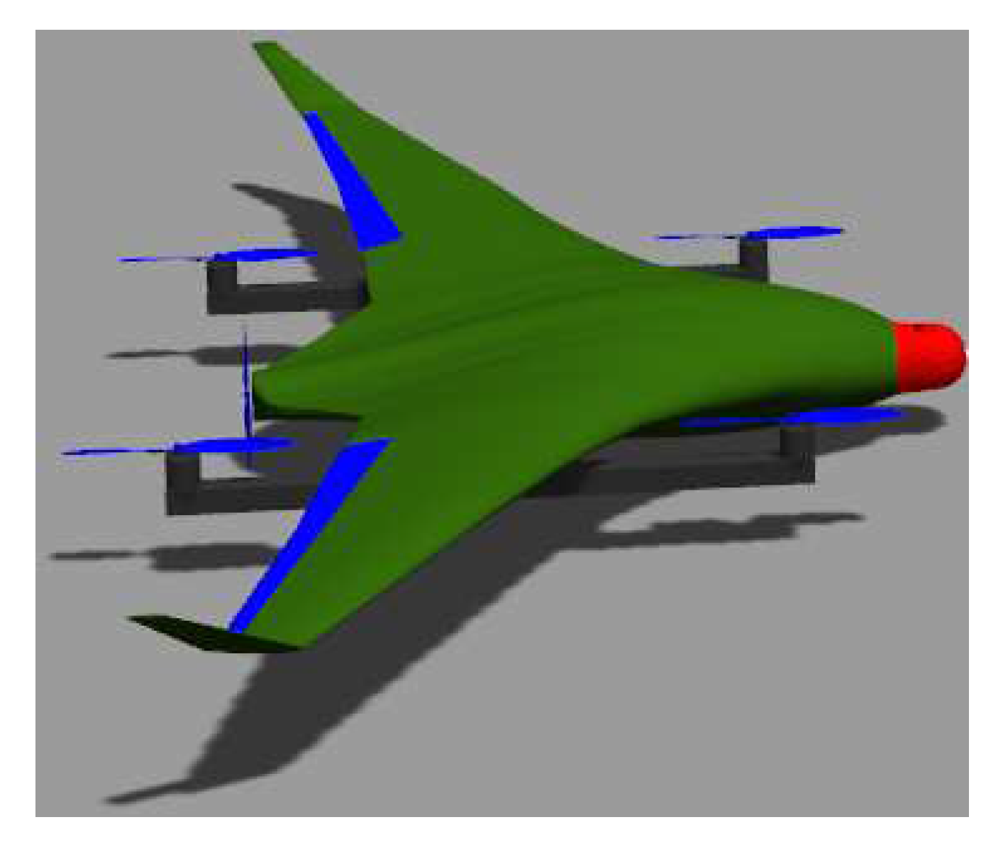
The assembled platform is nose mount on the BWB VTOL UAV as shown in
Figure 9. The roll joint is defined in SDF file of the vehicle model with attributes such as: parent (vehicle), child (Gimbal 1), and axis of rotation. For the pitch/yaw joint the parent is Gimbal 1 and the child is Gimbal 2. Platform controller custom Gazebo plugin was written and included into list of Gazebo plugins. The shared library generated from this plugin source code is called in the roll and pitch/yaw joints so that the attributes can be loaded to Gazebo physics engine to perform and control rotational dynamics of the gimbals.
5. Results and Discussion
The custom UAV airframe and sensor platform models shown in
Figure 6 and
Figure 8, respectively, are assembled and all the aforementioned technical procedures are followed in configuring and customizing both PX4 SITL and Gazebo simulator. A custom module that directs sensors on the steerable platform along flight path of the UAV is written and added to PX4 flight stack. The objective of steering the platform is to detect any obstacle along the flight path. The module subscribes to velocity vector and attitude of the UAV and publishes actuator control commands that rotate gimbals of the sensor platform. A custom mixer is designed to take these control commands and mixes accordingly from which PWM signal is processed and sent to Gazebo simulation environment. The custom Gazebo plugin receives the PWMs and apply them to the two gimbals of the platform.
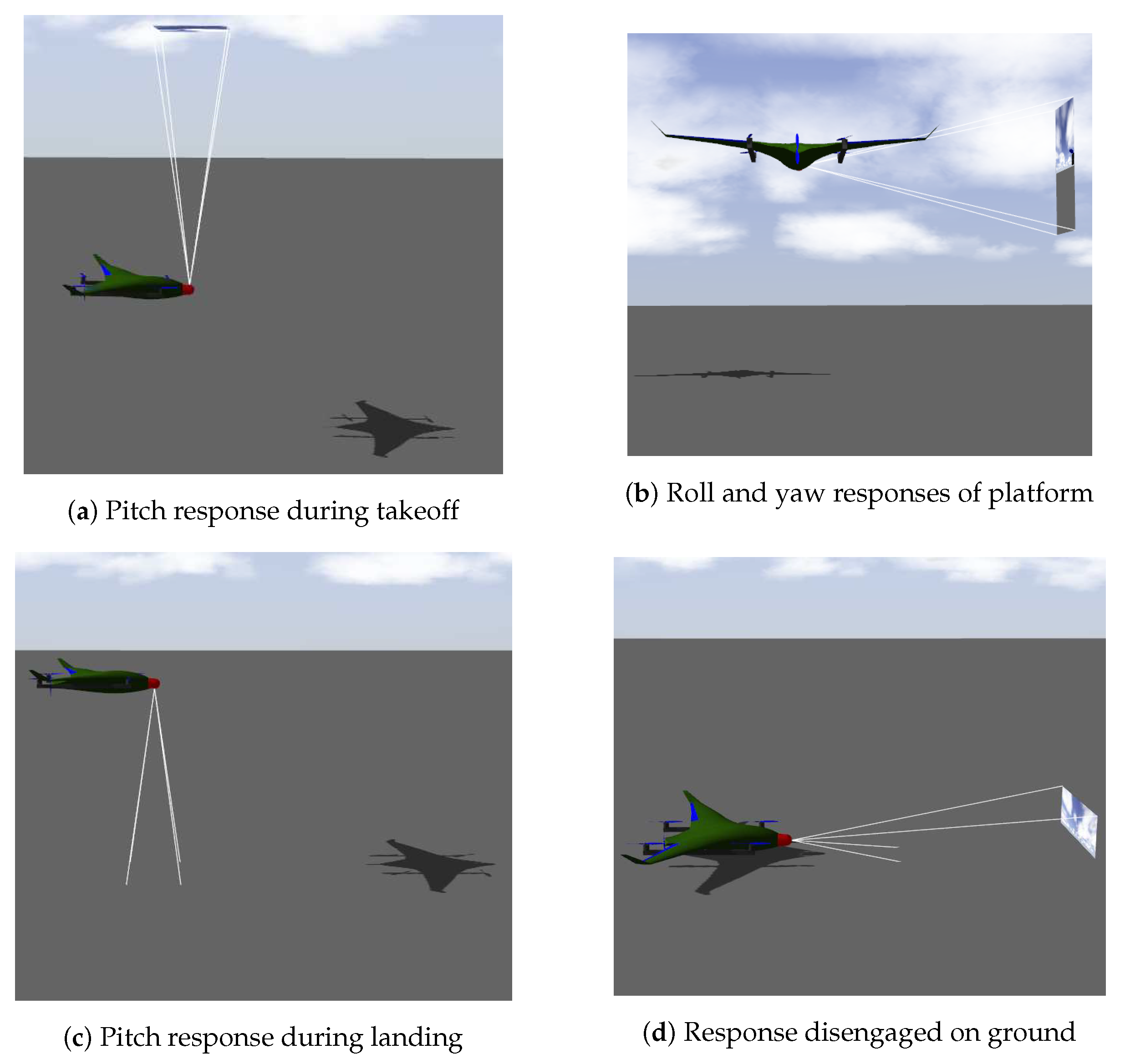
The corresponding values of model specific parameters of UAV and platform models such as mass, moment of inertia and aerodynamics are included to the SDF files of the two models. To investigate the responses of sensor platform to accurate and faulty values of the parameters, tests are conducted under different mission profiles: takeoff, slide side-way, navigate through waypoints, and return to launch are given to the UAV. To test whether the platform is steered in response to change in flight modes of the UAV, the UAV is commanded to take-off to certain altitude, slide side-way, and then land. Under such mission profile, both gimbals of the platform are engaged to roll and pitch/yaw the platform in such a way that the sensors onboard the platform are directed towards the velocity vector of the UAV.
With all parameters correctly valued, the UAV was commanded to take-off as shown in
Figure 10a During take-off, gimbal 2 automatically steered up to engage sensors for scanning the environment above the UAV. The UAV attains an altitude of 8 meters, descends down to 4 meters and slides side-way for a meter.
Figure 10b shows the roll and yaw responses of sensor platform as the UAV slides side-way. Then, the UAV descends to land as shown in
Figure 10c where Gimbal 2 is pitched downward while the UAV was landing and disengaged soon landing is detected as shown in
Figure 10d. This test validates that the responses of the sensor platform is according to the requirements.
Following the verification of the proper responses of the sensor platform, the values of mass and elements of moments of inertia of the platform are slightly changed and the UAV is commanded to take-off to certain altitude and return to launch. The faulty values of masses (
) and elements of moments of inertia (Inertia =
) given in
Table 2 are introduced to inertial attributes of sensor platform in SDF file of the custom model.
and
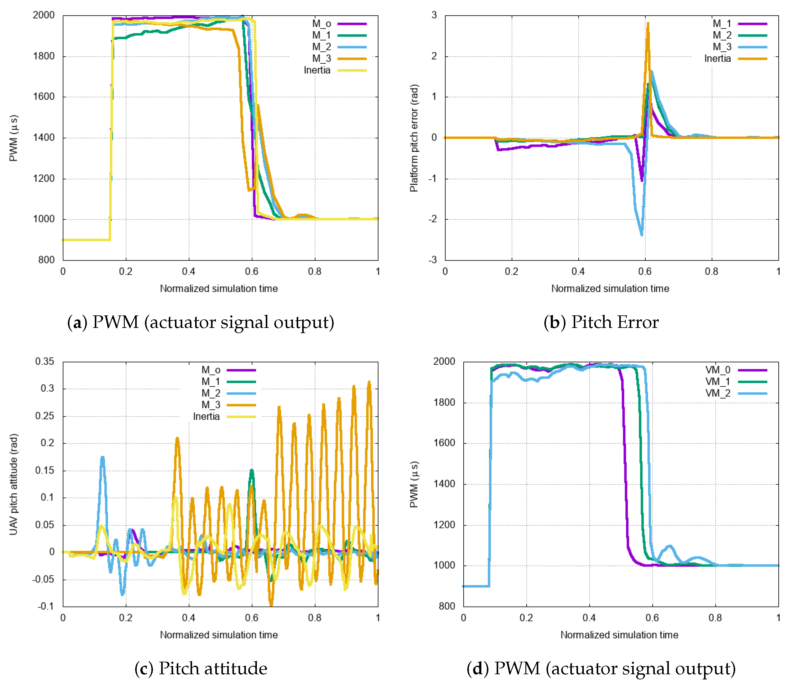
are the accurate values of mass and inertial elements of the sensor platform. The UAV is commanded to takeoff and land for each of the parameters given in the table. Under such faulty values of the model parameters, the actuator output signals received by the gimbals of the platform are plotted as shown in
Figure 11a.
The PWM values of the actuator outputs are substantially affected by the faulty values of the parameters. A drastic increase in the platform pitch error for increased error in its parameters is observed in
Figure 11b. These wrong values of mass and moment of inertia affect not only the pitch responses of the platform but also the attitude of the UAV.
Figure 11c shows UAV’s pitch attitude responses to different platform masses and inertial values. Since the sensor platform control module subscribes to UAV attitude values, such unstable inputs are introduced to actuator output signal calculation and affect the outcomes. The effects of mass and inertial parameters of the UAV on the responses of platform are also considered. The faulty masses (
and
) where
, as shown in
Figure 6, are given to SDF file of the UAV model. It is observed that changes in mass of the UAV affects actuator signal output as shown in
Figure 11d. The changes in inertial parameters of the UAV show no significant effect on the pitch response of the platform.
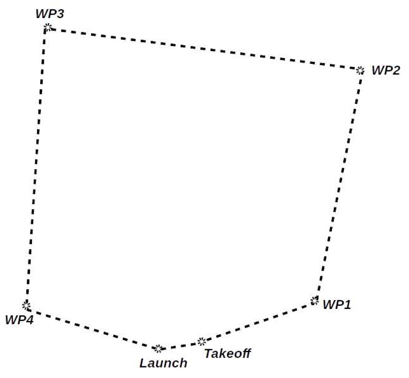
In another mission profile, the UAV is commanded to navigate through the waypoints shown in
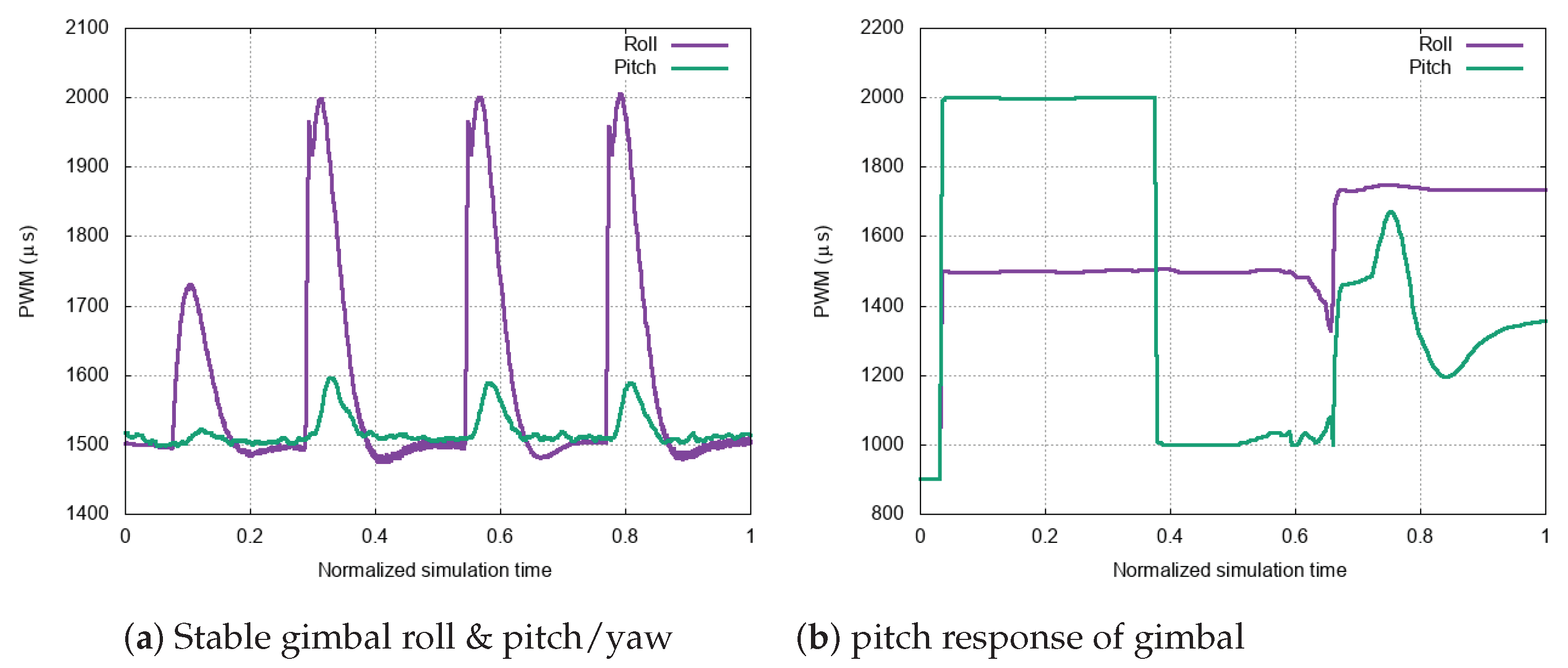
Figure 12 and return to launch. For reference, the UAV was commanded to navigate through the waypoints while all the parameters are given accurate values in SDF file. The UAV navigates through the waypoints with gimbals of the platform undergo roll and pitch/yaw, as shown in
Figure 13a to scan the environment along the flight course, accordingly. The amount of rotation of roll, pitch, or yaw of the gimbals corresponde to the amount of the change in velocity vector of the UAV. The change in velocity vector or flight course of the UAV at waypoint 1 (
) is lesser than the changes at other waypoints. In other words, the UAV requires to make relatively sharp turns at waypoints
,and
as compared to a turn at
. As a result, the amount of rotations of gimbals as shown in
Figure 13a (as PWM peaks) at the waypoints correspond to the amount of change in velocity vector of the UA. The first PWM peak in
Figure 13a corresponds to
.
The same mission is given to the UAV, under all model specific parameters of the two models set correctly except lift coefficient (aerodynamic parameter) of the UAV. Inaccurate value of lift coefficient (
of its accurate value) is introduced to the SDF file of the UAV model. During takeoff, gimbal 2 pitches upward as shown in
Figure 13b (PWM = 2000
s) while gimbal 1 remains fixed. This enables the platform to orient the sensors towards the velocity vector of the UAV. There is no effect on the UAV in this flight mode (multicopter mode up to 0.6 normalized simulation time). However, the moment the flight mode is switched to fixed-wing mode (for cruise), the UAV stumbles and fails out of the sky to which unstable roll and pitch responses of the platform is show in
Figure 13b.
It is extreme condition that the UAV fails out of the sky. With little errors in values of aerodynamic parameters, the UAV may manage to execute the mission. Mitigating the cause of error would be challenging if multiple aerodynamic variables are given random values and any module development and test under such circumstance outputs inaccurate results and jeopardize the fidelity of the module for practical use case. From aerodynamic parameters, effect of inconsistent lift coefficient value is considered. The study can be extended to the remaining aerodynamic parameters. However, the above tests suffice the importance of incorporating model specific parameters into SITL simulation process.
6. Conclusion
SITL software are essential tools for safe and rapid development of new algorithms. However, their reliability is to the extent they are carefully customized by incorporating parameters affecting the development and testing of the new algorithms into the simulation processes. In this work, impacts of model specific parameters on custom module development are investigated. To address proper customization of PX4 SITL and Gazebo simulation environment, technical steps are presented. These technical steps are of interest for complete novices and practitioners who seek to test and modify their own algorithms in realistic SITL simulation tools prior to actual scenario. The technical steps presented for PX4 SITL customization can, also, be used to customize the PX4 autopilot firmware for actual scenario.
As case study, a custom module that steers sensor platform for obstacle avoidance is tested in PX4 SITL simulation with custom UAV and sensor platform models. Inconsistent values of parameters of the models are given and their effects are analyzed. It is shown in the simulations that a single faulty value of a parameter of either models affects the dynamics of both models. The above simulation results highlight the importance of proper customization of PX4 SITL software tool for developing and testing custom modules.
Author Contributions
In this manuscript, design, development, and configuration of custom module and models in PX4 SITL and Gazebo simulation environment are done by T.A. and L.S. The overall conceptual design techniques followed in this manuscript was designed by K.S.
Funding
This work was supported by the BK21 FOUR program through the National Research Foundation of Korea (NRF) funded by the Korean government (grant number: 5199990714521).
Acknowledgments
This work was supported by the BK21 FOUR program through the National Research Foundation of Korea (NRF) funded by the Korean government (grant number: 5199990714521).
Conflicts of Interest
Authors mentioned in this manuscript have strongly involved in this study from the start to the end. The manuscript were thoroughly reviewed by the authors before it’s submission to the journal. This manuscript has not been submitted to another journal for publication.
References
- Antal, H.; Peter, B.; Mihaly, N.; Erno, S.; Adam, K.; Gergely, I.K.; Istvan, D. Software-in-the-loop simulation of the forerunner UAV system. IFAC-PapersOnLine 2022, 14, 139–144. [Google Scholar] [CrossRef]
- Michele, V.; Nicola, D.; Maria, L.B.; Davide, T. A Software-in-the-Loop Simulation of Vehicle Control Unit Algorithms for a Driverless Railway Vehicle. Applied Sciences. [CrossRef]
- Calvin, C.; Michal, P.; Nathan, V.H. Software-and Hardware-in-the-Loop Verification of Flight Dynamics Model and Flight Control Simulation of a Fixed-Wing Unmanned Aerial Vehicle★. Workshop on Research, Edu. & Devel. of UAS, Cancun Mexico. https://digitalcommons.usu.edu/cgi/viewcontent.cgi?article=1109&context=mae_facpub.
- Sooyong, J.; Yongsub, K.; Woo, J.L. Software-in-the-Loop Simulation for Early-Stage Testing of AUTOSAR Software Component. IEEE 2016. [Google Scholar] [CrossRef]
- Giovanni, M.C.; Milad, A.T.; Alessandro, A.; Mariano, A.; Fabrizio, M. Software-in-the-loop simulation of a test system for automotive electric drives. IEEE 2016. [Google Scholar] [CrossRef]
- Xiang, Ch.; Meranda, S.; Tuhin, D.; Xiaoqun, Ch. Real Time Software-in-the-Loop Simulation for Control Performance Validation. Simulation 2008. [Google Scholar] [CrossRef]
- Johannes, M.; Alexander, S.; Stefan, K.; Uwe, K.; Oskar, von S. comprehensive Simulation of Quadrotor UAVs Using ROS and Gazebo. Springer 2012. [CrossRef]
- Babatunde A., O. The role of CACSD in contemporary industrial process control. IEEE Control Systems Magazine 1995, 15, 41–47. [Google Scholar]
- Aziz, El F.; Adnane A.; Zouhair G. Real-time Software In the Loop Simulation for PID Control of the Nanosatellite Reaction Wheel. 2nd International Conference on Innovative Research in Applied Science, Engineering and Technology, Morocco 2022. [CrossRef]
- Soo H.H.; Seong-Gyu, Ch.; Kwon, S. real-time software-in-the-loop simulation for control education. Computer Science 2011. https://www.semanticscholar.org/paper/REAL-TIME-SOFTWARE-IN-THE-LOOP-SIMULATION-FOR-Han-Choi/698f704350b54412ae0e21610be3902462913f27#citing-papers.
- Wook, H.K.; Soo, H.H.; JoonSok, L.; Seong-Gyu, Ch. Real-Time Simulation Using Two Personal Computers for Control Education. IFAC Proceedings 2000, 33, 265–270. [Google Scholar]
- Graham, W.; John, M.; Glenn, B. Exploring Civil Drone Accidents and Incidents to Help Prevent Potential Air Disasters. Aerospace 2016. [Google Scholar] [CrossRef]
- Shoaib, M. and Mana, S. Software-in-the-loop simulation of a quadcopter portion for hybrid aircraft control. IOP Conference Series Materials Science and Engineering 2018. [CrossRef]
- Khoa, N.; Cheolkeun, H.; Jong, T.J. Development of a New Hybrid Drone and Software-in-the-Loop Simulation Using PX4 Code. Intelligent Computing Theories and Application 2018. [Google Scholar] [CrossRef]
- Adriano, B.; Helosman, V.F.; Poliana, A.G.; Alessandro, C.M. Guidance Software-In-the-Loop simulation using X-Plane and Simulink for UAVs. International Conference on Unmanned Aircraft Systems 2014. [Google Scholar] [CrossRef]
- Meier, L.; Honegger, D.; Pollefeys, M. A node-based multithreaded open source robotics framework for deeply embedded platforms. IEE Int. conf. on Robotics and Automation, USA, 2015. [Google Scholar] [CrossRef]
- Fabio, D’U.; Corrado, S.; Federico, F.S. An integrated framework for the realistic simulation of multi-UAV applications. Computers & Electrical Engineering 2019, 74, 196–209. [Google Scholar] [CrossRef]
- Massimiliano, De B.; Fabio, D’U.; Fabrizio, M.; Giuseppe, P.; Corrado, S. 3D simulation of unmanned aerial vehicles. XVIII Workshop CEUR-WS 2017. https://ceur-ws.org/Vol-1867/w2.pdf.
- Pitonakova, L.; Giuliani, M.; Pipe, A.; Winfield, A. Feature and performance comparison of the V-REP, Gazebo and ARGoS robot simulators. Lecture Notes in Artificial Intelligence 2018. [Google Scholar] [CrossRef]
- Marian, K.; Johann, L.; Stephan, R.; Simon, S.; Roland, G. Comparing Popular Simulation Environments in the Scope of Robotics and Reinforcement Learning. Robotics 2021. [Google Scholar]
- Dronecode: Simulation of Custom models in Gazebo. https://discuss.px4.io/t/simulation-of-custom-models-in-gazebo/19037.
- Dronecode: Specify Vehicle Parameters (Startup File) in SITL. https://discuss.px4.io/t/specify-vehicle-parameters-startup-file-in-sitl/13267.
- Dronecode: Gazebo simulation issue. https://discuss.px4.io/t/gazebo-simulation-issue/17898.
- Dronecode. Gazebo Simulation. https://discuss.px4.io/t/gazebo-simulation/18321.
- PX4-SITL_Gazebo: Iris (quadrotor) Gazebo (PX4) Model Modification. https://github.com/PX4/PX4-SITL_gazebo/issues/620.
- Dronecode: Create custom model for SITL. https://discuss.px4.io/t/create-custom-model-for-sitl/6700.
- Dronecode: Custom UAV Model to SITL. https://discuss.px4.io/t/custom-uav-model-to-sitl/26861.
- Dronecode: PX4 SITL with Gazebo - Custom Vehicle Model. https://discuss.px4.io/t/px4-sitl-with-gazebo-custom-vehicle-model/12066.
- Dronecode: New custom drone SITL Gazebo. https://discuss.px4.io/t/new-custom-drone-sitl-gazebo/27768.
- Dronecode. Questions about SITL from a beginner. https://discuss.px4.io/t/questions-about-sitl-from-a-beginner/2505.
- Dronecode. How does PX4 SITL simulation works? https://discuss.px4.io/t/how-does-px4-sitl-simulation-works/19239.
- Gazebo answers. Unable to add textures while following tutorial. https://answers.gazebosim.org/question/27534/unable-to-add-textures-while-following-tutorial/.
- Gazebo answers. Gazebo crash when loading a model. https://answers.gazebosim.org/question/27515/gazebo-crash-when-loading-a-model/.
- Gazebo answers. Exporting model and textures from Blender. https://answers.gazebosim.org/question/23398/exporting-model-and-textures-from-blender/.
- Gazebo answers. Gazebo plugin for ZED2 camera? https://answers.gazebosim.org/question/27477/gazebo-plugin-for-zed2-camera/.
- Mohamed, F.S.A.; Girma, T.; Jaerock, K. Software-in-the-Loop Modeling and Simulation Framework for Autonomous Vehicles. IEEE 2018. [Google Scholar] [CrossRef]
- Nathan, K. and Andrew, H. Design and use paradigms for Gazebo, An open-source multi-robot simulator. Int. conf. on intelligent robots and systems, Japan, 2004. [Google Scholar]
- Kun, X.; Shaochang, T.; Guohui, W.; Xueyan, A.; Xiang, W.; Xiangke, W. XTDrone: A Customizable Multi-Rotor UAVs Simulation Platform. https://arxiv.org/pdf/2003.09700.pdf.
- Khoa, N.D. and Trong, T.N. Vision-Based Software-in-the-Loop-Simulation for Unmanned Aerial Vehicles Using Gazebo and PX4 Open Source. International Conference on System Science and Engineering (ICSSE) 2019. https://ieeexplore.ieee.org/stamp/stamp.jsp?tp=&arnumber=8823322.
- Jesus, G. and Jose, M.M. Simulation in Real Conditions of Navigation and Obstacle Avoidance with PX4/Gazebo Platform. Workshop on Unmanned aerial vehicle Applications in the Smart City 2019. https://ieeexplore.ieee.org/stamp/stamp.jsp?arnumber=8730764.
- Kim, T.; Kim, D.; Kim, S. Improved Optical Sensor Fusion in UAV Navigation Using Feature Point Threshold Filter. Int. J. Aeronaut. Space Sci. 23, 157 – 1682022. [CrossRef]
- Duoxiu, H.; Wenhan, D.; Wujie, X. Proximal Policy Optimization for Multi-rotor UAV Autonomous Guidance, Tracking and Obstacle Avoidance. Int. J. Aeronaut. Space Sci. 23, 339–3532022. [CrossRef]
- OpenVSP. NASA open source parametric geometry. http://openvsp.org/.
|
Disclaimer/Publisher’s Note: The statements, opinions and data contained in all publications are solely those of the individual author(s) and contributor(s) and not of MDPI and/or the editor(s). MDPI and/or the editor(s) disclaim responsibility for any injury to people or property resulting from any ideas, methods, instructions or products referred to in the content. |
© 2023 by the authors. Licensee MDPI, Basel, Switzerland. This article is an open access article distributed under the terms and conditions of the Creative Commons Attribution (CC BY) license (http://creativecommons.org/licenses/by/4.0/).
