Preprint
Article

System-Level Assessment of Massive MIMO With RIS in C-RAN and IoT Networks in Sub-6 GHz, MM-Wave and THz Bands

Altmetrics

Downloads

134

Views

40

Comments

0

A peer-reviewed article of this preprint also exists.

Submitted:

01 December 2023

Posted:

04 December 2023

You are already at the latest version

Alerts
Abstract
In this paper we investigate in different scenarios the feasibility of using massive multiple-input multiple-output (mMIMO) with Reconfigurable Intelligent Surfaces (RISs) to boost the throughput and coverage performances with high energy efficiency, considering sub-6 GHz, mmWave and THz bands. With that objective, a centralized radio access network (C-RAN) suitable for beyond fifth generation (B5G) systems is considered, where we integrate the base stations (BSs) with multiple RISs and devices or user equipment. RISs with a large number of quasi-passive reflecting elements constitute a low-cost approach capable of shaping the radio wave propagation and improve wireless connectivity. We consider a scenario where multiple RISs are combined with mMIMO in the uplink in order to provide connectivity to Smart City (thousands of active low power devices) wirelessly, in the 3.6GHz and 28GHz bands. We also address a scenario where RISs are adopted with mMIMO in the downlink so as to offer connectivity to a Stadium with Pitch, (thousands of active user equipment) in the 28GHz band. Finally, we have also studied the connectivity at 100GHz of a Factory where several RIS panels replacing most of the BSs equipped with mMIMO assure improved throughput and coverage. We concluded that RISs are capable of improving the performance in any of these analyzed scenarios at the different frequency bands, justifying that they are a key enabling technology for 6G.
Keywords: 
Subject: Engineering  -   Telecommunications

1. Introduction

Current fifth generation (5G) technology is capable, efficient and flexible, but can be further improved. With densification of cellular networks, where each cell has an identical capacity, covering the same area with smaller cells allows to support more traffic. As a result, 5G supports higher traffic per cell than fourth generation (4G), which is also due to higher available bandwidths and more efficient transmission modes that allow to send more bits per frequency unit. The use of network densification is a key player in 5G requiring a wide deployment of small cells thus increasing the infrastructure cost and reducing the energy efficiency (EE). Reconfigurable Intelligent Surfaces (RISs) are also capable to increase the throughput and coverage performances with high EE. Therefore, they can potentially be the right replacement of sites with BS as they do not increase the infrastructure cost and increase the EE. Orthogonal frequency division multiplexing (OFDM), and mMIMO systems [1] are two of several pillars of 5G technology that works in both bands, below 6 GHz and above 24 GHz (mmWave) according to 5G New Radio (5G NR) [2], accommodating more users than the 4th generation. The use of the mMIMO approach, allows achieving 100x higher efficiency without requiring additional base stations (BSs). Non-orthogonal multiple access (NOMA) [3] is used in wideband networks and can accommodate an higher number of users and streams, but fails to achieve an higher EE that is required to meet the challenges and requirements of beyond 5G (B5G) and future generations (6G). Another 5G technology is carrier aggregation, which started in 4G and allows users to be served by carriers from 5G NR and LTE-Advanced at the same time [4]. This requires from the terminals support to work at different frequency bands, namely, sub-6GHz and beyond 24 GHz. Cloud or centralized radio access network (C-RAN) is another primary component of 5G to mitigate the effects of users located at cell borders. As networks grow exponentially in size, cloud alone is not enough, and edge computing is essential. Security is also part of the 5G technology and is deployed on large scale such as in software-defined networks (SDNs), and network function virtualization (NFV), where software-level components can be attacked [5].
Another use case of 5G is massive Internet of Things (mIoT) or massive Machine Type Communications (mMTC) supporting 5G IoT use cases with billions of connected devices and sensors. The use case covers both low-data-rate/low-bandwidth devices with infrequent bursts of data requiring long battery life as well as very-high-bandwidth/data-rate devices. The billions of devices represent a real challenge in current 5G wireless networks [6,7]. To support the massive connectivity of devices, powerful and versatile BS are required close to the data centers. mMIMO has the capability to vastly increase spectral efficiency (SE) and EE. Moreover, mMIMO has the capacity to support the massive connectivity of IoT devices as has already been shown in the literature [8,9]. In general, a single cell can be used to support IoT networks, such as a smart factory. However, for a smart city scenario there is the need of a cellular network and a C-RAN. In this article we assume that the number of IoT devices is greater than the number of service antennas in mMIMO. Orthogonal reference signals (RS) are reused in each sector of a cell with a transmission and reception point (TRP) consisting of a mMIMO. Our objective is to serve as many low-rate devices as possible, given the time and bandwidth of coherence of the channel characteristic of the Smart City scenario.
RIS can be synthesized as an “intelligent” surface comprising a large set of periodic elements that can change the phase (and also the amplitude) of incident waves [10]. RIS may be attached to practically any surface, including walls, furniture, building panels, and clothes. Since RISs have low power consumption and the possibility to be embedded in surrounding objects, these surfaces can be seen as a cost-effective solution for future wireless networks [11]. We extend our previous work in [31], where we presented for RIS-empowered systems an iterative algorithm for accomplishing the joint design of the access point precoder and phase-shifts of the RIS elements considering a multi-stream MIMO-OFDM link. The strategy aimed to maximize the achievable rate in a multicarrier point-to-point MIMO communication. The proposed algorithm used the alternating maximization (AM) method to decouple the optimization variables and split the main problem into two simpler ones. The first subproblem was solved using the singular value decomposition (SVD) combined with water filling whereas the second one was addressed with the accelerated proximal gradient (APG) approach. The resulting algorithm was designated as AM-SVD-APG iterative algorithm. The emphasis of this article is the joint precoding and RIS optimization and finding the best places to position the RIS for downlink communications.
B5G networks using radio access virtualization strategies and advanced computational platforms will exploit network densification. The virtual cell concept removes the traditional cell boundary for the end device and provides a consequent reduction in the detrimental “cell-edge experience” by the end device. Traditionally, devices are associated with a cell and, as a consequence, the link performance may degrade as a terminal is located far away from the cell center. In a C-RAN, the network determines which BSs are to be associated with each device. It seems that the cell is moving with the device in order to provide a cell-center experience throughout the entire network. Each device is served by its preferred set of BSs. The actual serving set for a device may contain one or multiple BSs and the device’s data are partially or fully available at some or a small set of potential serving BSs. The BS controller (central processor) will accommodate each device with its preferred set and transmission mode at every communication instance while considering load and channel state information (CSI) knowledge associated with the BS [12].
We will consider 5G NR system [13,14,15,16,17], using scalable OFDM numerology introducing specific subcarrier spacing (SCS), transmission time interval (TTI), cyclic prefix (CP) and the number of slots. Higher numerology indices correspond to larger SCS. The numerology index n depends on various factors (i.e., service requirements, deployment type, carrier frequency, etc.). The introduction of wider SCS is essential for mitigating inter-carrier interference (ICI) and phase noise at millimeter-wave (mmWave) and Terahertz (THz) frequencies. The Transmission Time Interval (TTI) assumes smaller values ranging from 1 ms to 31.25 µs, for numerology 0 and 5, respectively. 5G NR was designed to lower interference and increase EE by reducing always-on transmissions, which is a crucial aspect to extend the lifetime of IoT devices. 5G NR ensures forward compatibility as it is prepared for its future 6G evolution in use cases and technologies. At mmWave and THz frequencies, high capacity and extreme data rates are possible, even though higher frequencies introduce limitations in coverage due to increased signal attenuation [18]. 5G NR specifications are projected to accommodate dense urban and micro or indoor scenarios, but with the introduction of mmWave and THz, it can be more likely to have some part of the signal blocked by obstacles or severely affected by distance, which causes a substantial decrease in the signal strength becoming hard to compensate without the use of RIS elements and advanced signal processing [19,20].
The large distance attenuation that takes place in the mmWave and THz bands makes it difficult to achieve large coverage under the limitation of the maximum available terminal or BS transmit power. This phenomenon tends to worsen, especially in systems designed for outdoor environments. Another particular characteristic that is verified at mmWave and THz bands is that the propagation channel tends to be spatially sparse, which results in a lower number of propagation paths. Such challenges can be coped with the aid of RISs, since these devices can operate as a centralized beamformer that can increase the channel gains. Moreover, RIS can also create additional propagation paths around major obstacles and enable line-of-sight (LOS) links to distant receivers [21]. In [22] the authors studied a system operating at the THz band using a RIS for an indoor and outdoor scenario that optimizes the phase shifts of the individual elements in order to assist an ultra-massive MIMO (um-MIMO) communication link. Performance results showed that the approach was capable of effectively extending the communication range. The authors in [23], developed an algorithm to calculate the ideal phases for each RIS element in order to maximize the capacity of the transmission. In their study, a multiple-input multiple-output- OFDM (MIMO-OFDM) link with frequency-selective fading channel and perfect channel state information was considered.
According to the literature, due to their EE, RIS can be a viable alternative to traditional amplifiers and relays when considering multi-user communication scenarios, as demonstrated by the authors in [24]. The authors in [25] described a system with a single AP that distributes packets to several users. The system is able to improve the performance of both orthogonal multiple access (OMA) and NOMA with the aid of RIS. Although they considered only a single antenna for both transmitter and receiver, it was proved that RIS can enhance both the capacity and rate of the system. Nevertheless, point-to-point communications in MIMO systems aided by RIS are still a challenge. Although some results obtained with test bench prototypes exist in the literature [26,27], they all comprise small-scale configurations. Furthermore, the use of RIS-assisted systems combined with MIMO configurations in C-RAN requires more in-depth research into the optimization process and overall impact. In [28] it was considered a RIS-aided cellular network and also presented an algorithm for joint optimization of the active beamforming at the BS and passive beamforming of the RIS. Their simulation results showed some performance improvements against other existing algorithms. In [29], the authors presented one of the first system-level studies of a RIS-aided network deployment, using two frequencies of fifth generation new radio (5G NR) namely, 3.5GHz and 28GHz. While assuming a simplified operation in the far-field region with the RIS configured as anomalous reflectors, they demonstrated through a three-dimensional simulator how RISs can benefit a typical 5G urban network. Also, in [30], authors studied a system level design with an improved antenna model that analyses the path loss, power and overall coverage between the transmitter and receiver with the aid of relayed RIS. Their results showed that the impact of the placement of RIS can affect the performance of the system, especially at edges of the sector cell. Despite the promising results of these initial studies, more research on the integration of RIS in future wireless networks is required before large-scale experimental deployments can become a reality. In fact, at the mm-Wave or THz frequencies, the distances between BSs will tend to be short enabling users to be connected to more than one BS simultaneously.
We adopt the same optimization approach from [31], namely, the joint AM-SVD-APG iterative algorithm applied to the uplink and downlink to effectively enable the implementation of smart radio environments. The use of C-RAN is essential in order to increase the capacity, i.e., the number of active IoT devices of a Smart City scenario and improve the coverage and throughput of other outdoor and indoor scenarios, namely, Stadium with Pitch and Indoor Factory. The following is a summary of the article’s main contributions:
- We provide a system-level assessment of C-RANs including multiple RISs spread around BSs in three different scenarios at three different frequency bands, namely, 3.6GHz, 28GHz and 100GHz.
- The system-level evaluation for multi-stream MIMO-OFDM links is performed for numerologies 0 and 3 from 5G NR in three 3D scenarios with different parameters, number of transmitting/receiving antennas, bandwidth, frequency carrier, number of RIS elements, transmitting power, etc.
- System-level evaluation demonstrates that C-RAN deployments in all simulated scenarios, including urban Smart City, Stadium with Pitch and Indoor Factory, can achieve significant performance improvements over typical cellular networks without RIS, not only in terms of EE but also SE.
The article is organized as follows: Section 2 presents the model for the C-RAN system with RIS. Section 3 presents the System level configuration and scenarios that are considered in the evaluation. Section 4 presents and discusses system-level simulation results. The conclusions are outlined in Section 5.

2. System Model

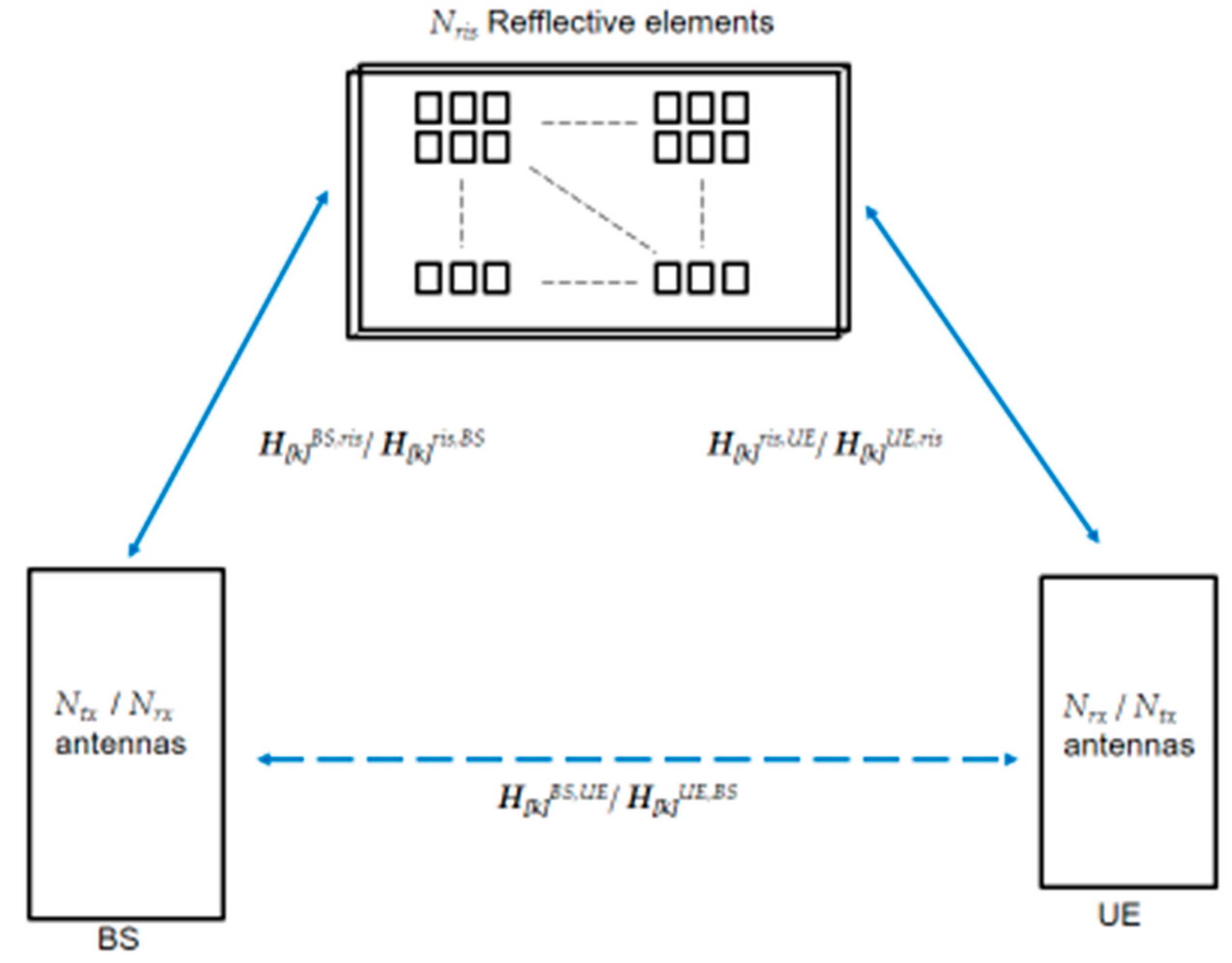
We consider Figure 1 as the basis of our communication system with RIS. It is assumed that the system uses OFDM to cope with frequency selective fading. In this study we consider three different scenarios, two of them are outdoor and indoor and the last one is indoor only. In every scenario there are surrounding obstacles that can easily block or obstruct the communication links. Such fact presents itself as critical especially in cases where direct LOS is used, or when the signal suffers attenuation losses. LOS and NLOS cases can be assisted with RIS panels. We consider the downlink and uplink of an OFDM-based mMIMO system, where a BS is equipped with Ntx / Nrx antennas transmits/receives to Nu users. Between each BS and the users are located plenty of RIS panels with NRIS reflecting elements. Each user equipment (UE), which can be a device or a pedestrian, is assumed to have Nrx / Ntx antennas, wherein that transmission/reception is composed by grouping the subcarriers into Nprb physical resource blocks (PRB), with 12 subcarriers in each at any given moment. We denote Ns as the total number of streams assigned to the antennas on each subcarrier with modulated symbols to be transmitted/received by the active antennas. In our scenarios the communication for different users is based on orthogonal multiple access and we adopt the optimization method that we proposed in [31], which jointly computes the precoder and the phase shifts of the RIS panels placed in the vicinity of the receiver and transmitter. Such strategy is aimed at the maximization of the achievable rate in a multicarrier point-to-point MIMO communication. The adopted algorithm uses the alternating maximization (AM) method to decouple the optimization variables and split the main problem into two simpler ones. The first subproblem is then solved using the singular value decomposition (SVD) combined with water filling whereas the second one is addressed with the accelerated proximal gradient (APG) approach. We refer to the resulting algorithm as AM-SVD-APG. Table I of [31], summarizes all steps of the proposed joint precoding and RIS optimization algorithm AM-SVD-APG. This method relies on iteratively applying a gradient-based step, followed by a proximal mapping.
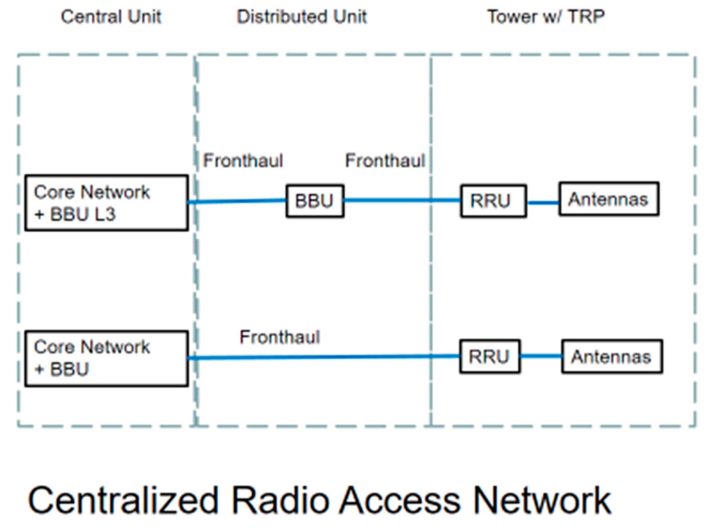
5G mobile network operators (MNO) are looking to adopt open, virtualized, C-RAN networks for greater network flexibility and cost savings. MNOs move their networks from physical hardware to virtual and cloud-based software deployments since 4G. This step towards virtualization is well underway for the core network. This goal is also valid for the RAN of 5G and B5G. Cell site antennas have remote radio unit (RRU) connecting to the central office where the baseband unit (BBU) is localized, with the option of intermediate distributed units with intelligence processing as shown in Figure 2. The processing power distribution between BBU versus RRU depends on the specific use case and scenario. In Figure 2, each Transmission and Reception Point (TRP) is equipped with one uniform planar array (UPA) of antennas per sector.

2.1. Scenarios based on 5G New Radio 3D Scenarios

There are several 5G test scenarios [13,14]. In this article, we have considered three modified scenarios that are described next and later evaluated using OFDM with mMIMO and RIS communications.

2.1.1. Smart City

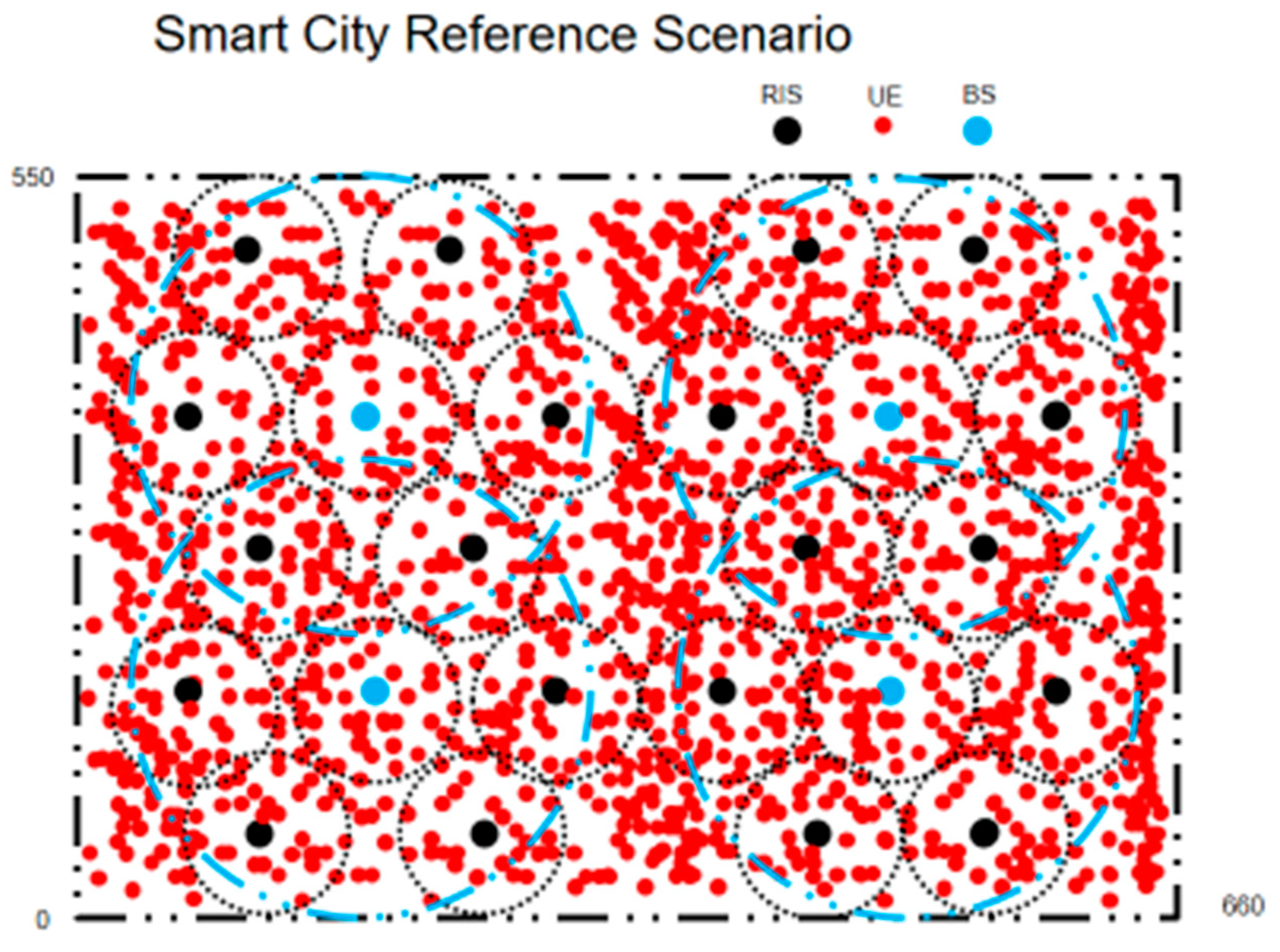
The Smart City scenario that we consider is based on a modified section of the urban micro cell with high device densities but with low traffic load per device in city centers and dense urban areas. This scenario is coverage-limited because of the small transmission power of devices. It has transmission and reception points (TRPs), with UPA antennas at a height of 10 meters. There are four sites with 3 TRPs one per sector. The inter-site distance (ISD) in this scenario is 400 m. The carrier frequency is 3.6 GHz and/or 28 GHz. The bandwidth for both carrier frequencies is 50 MHz. Full buffer model is assumed. At least a total of 2250 active devices are distributed per sector of each cell, with 50% of devices being indoor and the remaining 50% devices are outdoor in the streets, either static or with 3 km/h velocity. The layout of this scenario is illustrated on Figure 3.

2.1.2 Stadium with Pitch

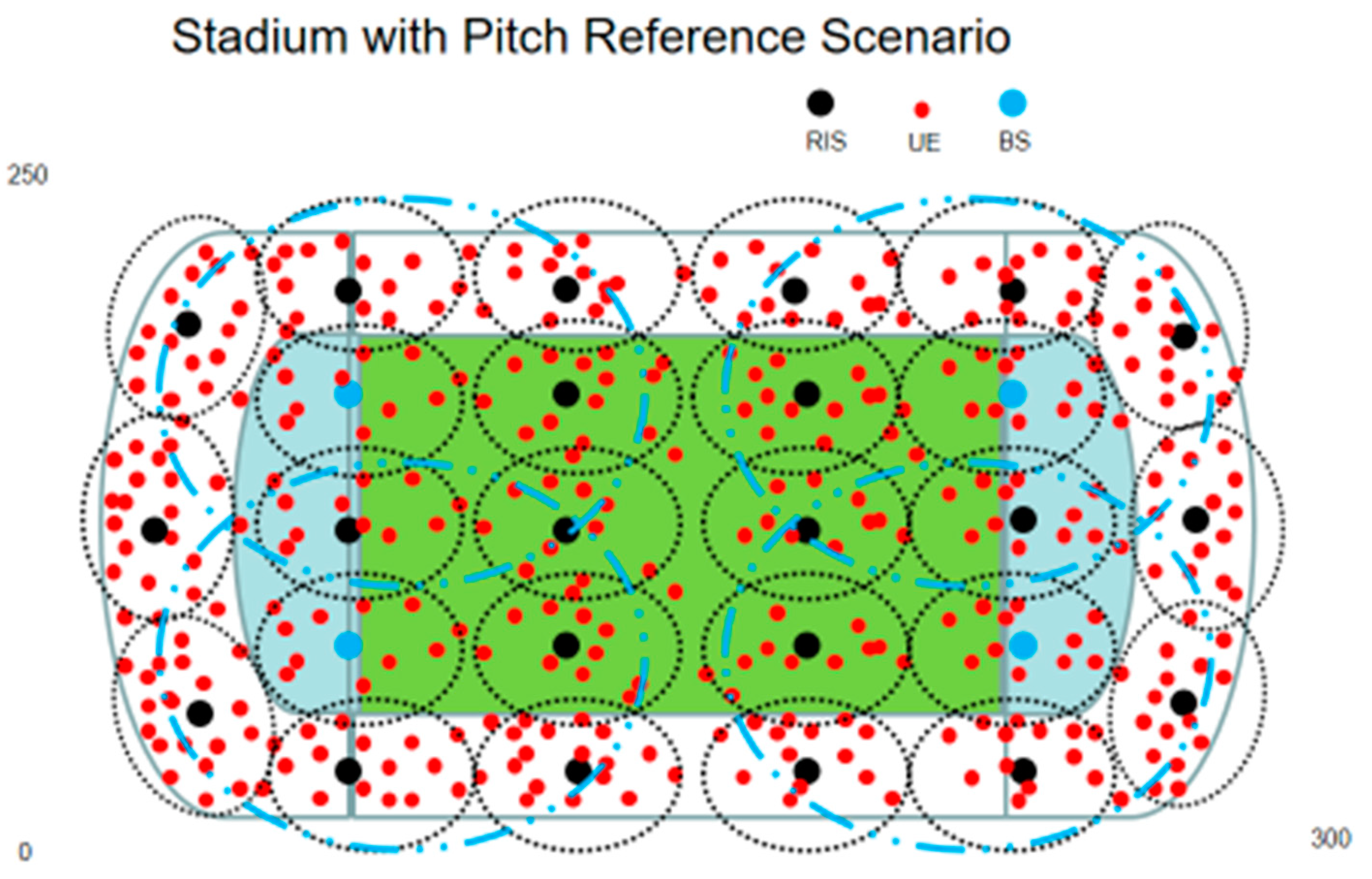
The Stadium with Pitch scenario representing Open-air Gathering that we evaluate takes a combination of urban micro cell’s multi-path fading with small cells and high user densities and traffic loads and indoor factory sparse density clutter with probability of LOS and NLOS in Stadiums with high user densities. This scenario is interference-limited, it has four sites with 3 TRPs one per sector. The ISD of this scenario is 108 m. The four sites have a BS antenna height 25 m. The carrier frequency and bandwidth for this scenario is 28 GHz and 400 MHz. Full buffer traffic model is assumed. A maximum of 3300 users (UEs) are distributed per sector with 46% of users being in the stadium turf and the remaining 54% are in the stadium stands. The layout of this scenario is illustrated on Figure 4.

2.1.3. Indoor Factory

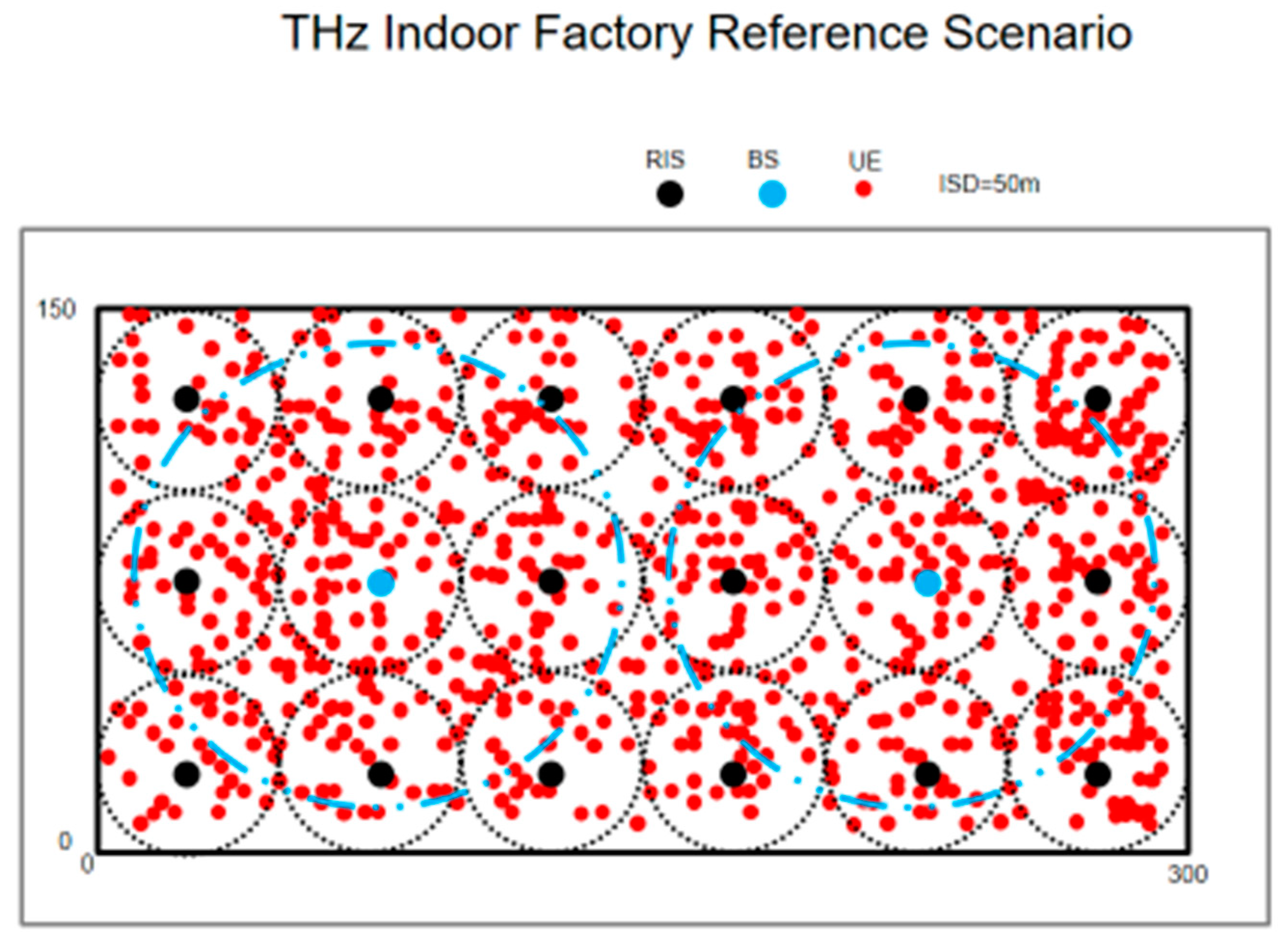
The indoor factory deployment scenario focuses on high user throughput or user density in factories. This scenario represents indoor factories with a total volume of 300 m × 150 m x 10 m. There are two sites with 3 TRPs one per sector. The ISD of this scenario is 150 m. In this case, the BS antenna height can be 2 m (low height) or 8 m (high height). It is also an interference-limited scenario. The carrier frequency is 100 GHz (sub THz band). We have chosen only high dense clutter factories. The minimum bandwidth is 400 MHz. Variable number of users per cell are distributed uniformly, and the exact number of users depends on the number of physical resource blocks received by each one. Full buffer model is assumed. The layout of this scenario is illustrated in Figure 5.
We have built 3D simulation channel models for the above-mentioned outdoor, and indoor scenarios for sub-6GHz, mmWave and THz frequencies. All the details about 3D simulation channel models can be found in [14]. For sub-6 GHz frequencies, up to a moderate number of antennas can be activated (i.e., 64). In mmWave frequency bands, the transmission is characterized by a considerable signal attenuation that limits the network coverage. To overcome this limitation, one of the key features is the adoption of a large number of multi-antenna elements having a given aperture to increase the transmission/reception capability of mMIMO and beamforming. Since managing transmissions in mmWave frequency bands is complicated, the beam needs to be optimized and adjusted each time, taking into account the conditions of the receiver and the RIS. However, for direct links between BS and users (or devices) without the involvement of RIS, the correspondence between the directions of the transmitter and receiver-side beams is performed by identifying the most suitable beam pair for both downlink and uplink.

3. System Level Configuration

In this section, we present the setup adopted for the C-RAN system level assessment, detailing the target scenarios that we will evaluate. In the C-RAN the static clustering technique partitions the network into three adjacent TRP sets where each user is served by at least one TRP, while the others perform inter-user interference. For C-RAN with cluster size one we have the traditional cellular system. For instance, with cluster size 3, the network is partitioned into three adjacent TRP sets where each user is served by three adjacent TRPs. The inter-user interference only comes from the other clusters. The considered scenarios are almost all based on modified 3GPP environments as specified on previous section: the Smart City environment, which corresponds to a modified Urban Micro Outdoor/Indoor environment; the Stadium with Pitch has no correspondence to any 3GPP environment but it corresponds to an Open-air Gathering environment; and the Indoor Factory that is based on the reference scenario of 3GPP with the same name for an indoor factory environment area (see Figure 3, Figure 4 and Figure 5).
In our study, the operating frequency was varying depending on the scenario. The bandwidth was also variable depending on the 5G NR numerology chosen for the scenario. The bandwidth was B=50 MHz for numerology 0 and B=0.4 GHz for numerology 3. In all scenarios the devices or terminals were uniformly placed within a minimum distance of 1 meter around their respective BSs and RIS panels. The red dots on the previous figures illustrating the scenarios represent the devices or users. The devices or users are randomly and uniformly placed in each scenario at a given distance and angle from the BSs or from the associated RIS panel. There is a probability of having LOS and NLOS links depending on the distance d. In the case of the NLOS links, there is fading due to multipath following a Rayleigh distribution with shadowing according to a Lognormal distribution. All parameters and equations can be found in [14]. For each scenario, the probability of LOS (PLOS) can be calculated as:
Smart City Scenario
{ P L O S = 1 , d < 18 P L O S = ( 18 / d + exp ( d / 36 ) × ( 1 18 / d ) ) , d > 18
Stadium w/ Pitch Scenario
{ k s u b = 44.8 × ( ( h B S h U T ) / ( 22.5 h U T ) ) , h B S = 25 P L O S = exp ( ( d / k s u b ) )
Indoor Factory Scenario
{ k s u b = 2.2 , h B S = 2 k s u b = 2.2 × ( ( h B S h U T ) / ( 6 h U T ) ) , h B S = 8 P L O S = exp ( ( d / k s u b ) )
where hBS, hUT are the BS and terminal antenna heights.
In all scenarios we first evaluate the case where only BSs are active, i.e., RIS are not active. In this case the coverage area of the BSs must include almost the whole scenario area. Large blue circles are illustrating this situation, for every scenario.
For the Smart City scenario one device can be connected to each corresponding RIS panel with a total of 20 RIS and 4 BS deployed. There are 5 RIS inside each BS coverage area, as represented in Figure 3. For the Stadium with Pitch scenario up to three users can also be connected to each corresponding RIS panel with a total of 22 RIS and 4 BS deployed. There are on average 5.5 RIS inside each BS coverage area, as represented in Figure 4. For the Indoor Factory scenario one user can be connected to each corresponding RIS panel with a total of 16 RIS and 2 BS deployed. There are 8 RIS inside each BS coverage area, as represented in Figure 5.
The total power transmitted by each BS or device depends on the scenario and the frequency carrier. At 100 GHz the power was set to 30mW (14.8dBm) for the Indoor Factory, whereas 3.16W (35dBm) or 250mW (24dBm) are transmitted from each BS at 28 GHz, in the case of Stadium. For the Smart City scenario, the power transmitted by IoT devices was set as 10mW (10dBm) both for 3.6 GHz and 28 GHz. Two types of links are considered, namely, a direct link between BS and devices or users and an indirect link through the RIS. For all scenarios, because of C-RAN there are always double-links, where devices or users are served simultaneously by a RIS and a BS. The noise power is N0= -85 dBm for the bandwidth B=0.4 GHz and N0= -94 dBm for the bandwidth B=50 MHz. The receiver noise figure F= 3dB. The spacing between each element of the RIS panel is dRIS= λ/2=42 mm (3.6GHz), dRIS= λ/2=5.4 mm (28GHz) and dRIS=1.5 mm (100GHz), resulting respectively in areas of A=1764 mm2, A=29.16 mm2 and A=2.25 mm2 per element. The gains of the individual antenna elements of the arrays are 0 dBi for both the transmitter and receiver.
Next, we present in Table 1, Table 2 and Table 3 the parameters considered for these scenarios.

4.1. Link-Level Simulations

The performance of the adopted scheme namely, the joint design of the precoder and phase-shifts of the RIS elements, is assessed considering a MIMO- OFDM link, and compared against other MIMO-OFDM systems. Monte Carlo simulations were run according to the system model presented previously.
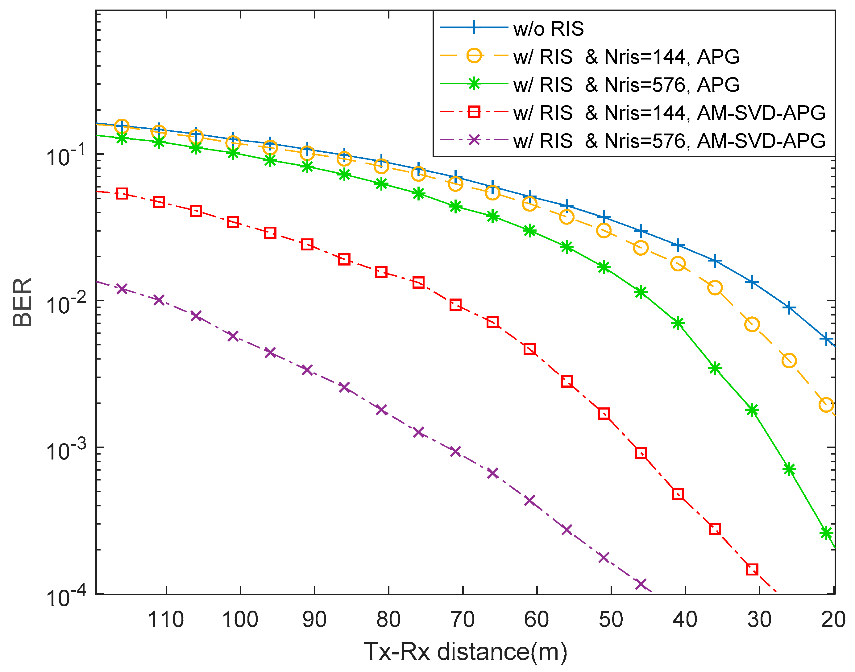
Figure 6 shows the BER performance versus the distance between the transmitter and the receiver. The distance between Tx—Transmitter and Rx—receiver is presented in the x axis on Figure 6. For this comparison we use a transmitted power of Puser=10dBm. We observe curves for five different configurations. The parameters used are: Ntx=64, Ns=3, Nrx=16, Nris=144 or 576 elements, and Nc=1. Curves with the proposed AM-SVD-APG algorithm are presented and assume the existence of direct and indirect links between transmitter and receiver. To compare with our algorithm, we include results obtained with the APG algorithm from [22]. It can be observed that our scheme clearly outperforms APG.

4.2. System-Level Simulations

The signal-to-noise ratio (SNR) in dB considered in the system-level simulations is obtained from SNR = (Es/N0) + 10log(Rs/B) dB, where Rs is the total transmitted symbol rate per antenna and user, B is the total bandwidth (we considered 50 MHz at 3.6 GHz and 28 GHz for Smart City with numerology 0, and 400 MHz at 28 GHz and 100 GHz for the other scenarios with numerology 3), and Es/N0 is the ratio of symbol energy to noise spectral density in dB. Values of Es/N0 are obtained from the link-level BER results. In this work we only considered QPSK modulated symbols. 5G NR frame structure has both frequency division duplex (FDD), used in the paired spectrum, and time division duplex (TDD), used for the unpaired spectrum. We chose TDD in this work for all scenarios.
The subcarrier spacing, transmission time interval, cyclic prefix (CP), and the number of symbols per slot, are all defined by the proposed 5G NR scalable OFDM numerology [15]. Our scenarios were simulated considering numerologies 0 and 3. Numerology 0 (4G) was chosen for Smart City scenario because the most important key performance indicator (KPI) is the coverage of IoT devices, not their throughput, and numerology 3 for the Stadium with Pitch and Indoor Factory scenarios, in mmWave and THz bands, respectively.
For Smart City scenario, we considered different UPA antenna arrays with Nrx= 144, 256 up to 576 elements at the receiver side (BS). For the device (transmitter side) Ntx=1, Ns=1 and Nc=1. For numerology 0, Δf=15KHz, every PRB has 12 carriers (Bprb=180KHz) with 14 symbols per subframe duration Ts = 1 ms, 168 (12 × 14) subcarriers. In real cellular networks with massive MIMO, there is a coherence interval where channel information does not change much, and pilot reference symbols must be retransmitted. The coherence interval is
τc = Tc × Bc
where coherence time Tc = 50 ms is well fitted for nomadic and static low-power IoT devices [32] and Bc=1.697MHz (9.42857x180KHz) is adequate to an urban city scenario such as Smart city. In τc the maximum number of subcarriers is Nsc=79200 (168 x 50 x 9.42857). Half of the coherence interval can be used for uplink data transmission, and the remaining half of the coherence interval can be used for downlink transmission. We need orthogonal reference pilots in uplink that must be subtracted from uplink data symbols. For uplink data and reference pilots, we must have Nsc/4=79200/4 = 19800 subcarriers. Assuming that we divide 19800 into twelve groups (scenario has 4 BS x 3 sectors), then we obtain 19800/12=1650 subcarriers, one for each device transmitting in each sector at the same time without any intra cell interference. Table 4 presents additional simulation parameters of the Smart City scenario. In real situation the number of active IoT devices per sector can be much higher because of the sleeping time of devices. Sensors do not need to transmit packets every 1 ms.
For the Smart City scenario, we consider only the uplink where devices are transmitting to BS and RIS at the same time. Uplink power control is appropriately applied so that the received powers are the same for almost all devices. However, data sent from devices that are too far from the receivers, i.e., BSs and/or RISs, might not be well received. There is a minimum received power that must be above the receiver sensitivity so that packets are correctly received. We take as reference the BER ≤ 5x10⁻⁴ to decide, which packets are received without bit error. For numerology 0 of 5G NR, Δf=15KHz and 168 subcarriers are being transmitted in every PRB during 1 ms. Minimum throughput of each device is 2 Kbps, assuming transmission in one carrier with QPSK symbols, and minimum spectral efficiency per device is ℇu=2/15 bps/Hz. There is a theoretical equation for the maximum throughput, assuming perfect power control and single cell with no inter-cell interference [33], which is:
Thmax = 0.5B × (1 − τp) × log2(1 + SINR)
where τp is fraction of time for pilot symbols transmission and B is the total bandwidth. SINR is the signal to interference plus noise ratio.
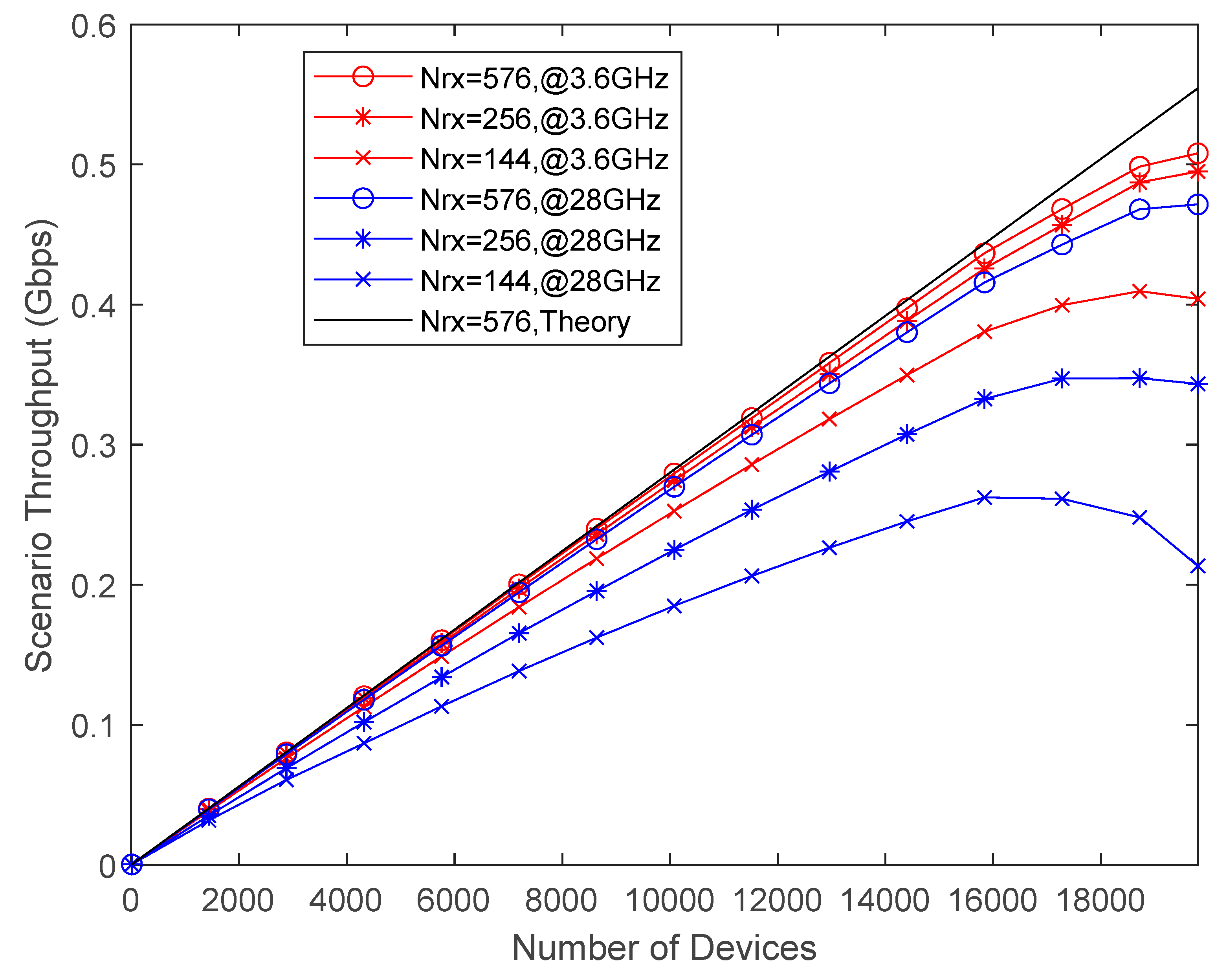
In Figure 7, it is shown the throughput performance versus number of users, for different number of antennas at BS in each sector of scenario, and for different frequency carriers. The throughput curves of Figure 7 were obtained with a maximum transmitted power of 10 mW. The settings are described in Table 1. In this scenario we used Ns=1, Nc=1, Ntx=1 and Nrx=144, 256 or 576 antennas. As expected, the frequency carrier of 3.6 GHz provides the highest throughput compared to 28 GHz due to its lower path attenuation. Increasing the number of UPA antennas allows serving effectively more devices at the same time. For almost all curves, as Nrx increases, the throughput increases up to a certain point, and then it decreases. Increasing Nrx provides higher throughput. The decrease of throughput after a certain Nu has to do with higher number of devices at the border of the cells with SINR below the reference to avoid errors in packet. Due to the C-RAN operation mode almost no reference pilot symbols contamination occurs. For 3.6 GHz the maximum simulated spectral efficiency occurs for Nu=19800 and Nrx=576, corresponding to ℇ=508/24.75=20.53 bps/Hz, where 508 Mbps is the aggregate throughput of 19800 devices and B=24.75 MHz is the occupied bandwidth. Theoretical maximum spectral efficiency is ℇmax=554/24.75=22.40 bps/Hz.
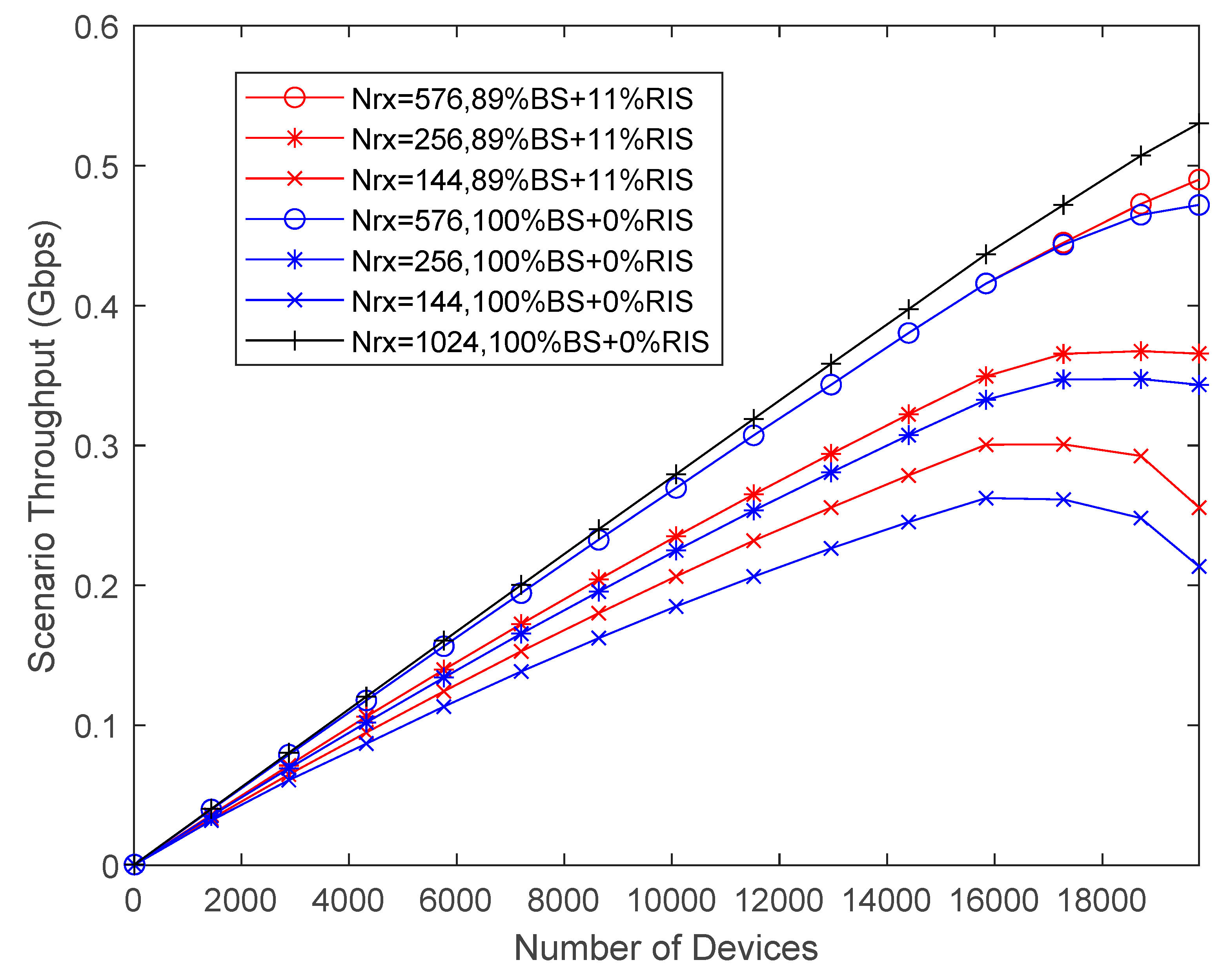
In Figure 8, it is shown the throughput performance versus Nu, for different number of antennas at BS in each sector, for carrier frequency of 28GHz, without and with RIS panels Nris = 576. We compare four standard communication curves without any RIS, only with BSs and devices, with three curves with RISs panels spread around the scenario. The former curves consist only of direct links between the devices and the receivers. The other cases consist of a combination of direct link connections and RIS-aided connections. They are represented as a percentage of devices that are transmitting signals to BS plus the percentage of devices also with RIS connections, namely as %BS + %RIS. For example, 100%BS+0%RIS, means that all devices are attached to the BSs, whereas 89%BS+11%RIS, represents 89% of spread out devices linked to nearest BS and the 11% remaining devices are linked to nearest RISs. C-RAN processes data received from the two best links involving each device. As expected, the introduction of RIS panels at cell borders provides higher throughput compared to BS only connections. As expected, increasing the number of receiving UPA antennas results in higher throughput due to their higher multiple access capability. The throughput gain introduced by RIS panels with Nris = 576 increases with decreasing number of UPA antennas Nrx = 576, 256 and 144. The gain is more noticeable for increasing Nu because more users become close to where RIS panels are localized at the cell borders. Only for 28GHz we have considered an UPA with Nrx = 1024 antennas because of its size. As expected, the maximum throughput is achieved for Nrx = 1024 due to its higher multiple access capability.
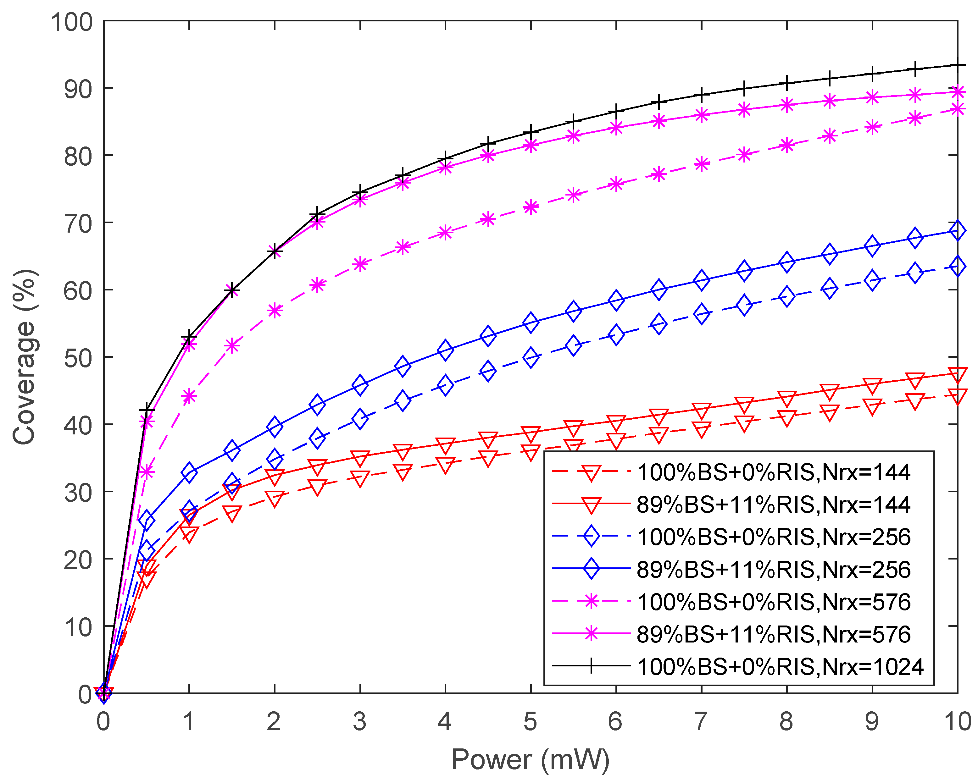
Figure 9 presents the coverage versus transmitted power for Nu=19800 with the same conditions of Figure 8. The comparison between Figure 9 and Figure 8 shows that there is a direct correspondence between the throughput performance and the associated coverage. For the maximum transmitted power of 10 mW, the smallest coverage of 44% is achieved by the curve 100%BS+0%RIS, Nrx = 144, whereas the highest coverage is 93% which is obtained by the curve 100%BS+0%RIS, Nrx = 1024. Thus, the maximum coverage gain is 111%. The next highest coverage of 90% corresponds to the curve 89%BS+11%RIS, Nrx = 576 and represents a coverage gain of 104% that includes a reduction of the number of antennas but the introduction of RIS. Still, the main contribution to the coverage gain is due to the number of antennas that is 97%.
Next, we test the Stadium with Pitch scenario with different parameters. For this purpose, we adopted a higher number of subcarriers Nc combined with more spatial streams and larger transmit powers. 5G NR numerology is 3, with Δf=120KHz, the bandwidth is 400MHz and 112 symbols are transmitted every millisecond. The maximum number of subcarriers is 3300. In this scenario the main KPI is throughput associated to the number of connections per unit of area. In all simulations in the Stadium the transmitter side BS has Ntx= 64, whereas the receiver side user has the same number of antennas namely, Nrx= 16. Different numbers of transmitted symbols per subcarrier were considered in the simulations, Ns=2 and Ns=3. The number of OFDM subcarriers (Nc) used in the evaluations is variable, namely, Nc = 12, 60, 120, 132, 216 or 240. All these numbers are multiples of 12, which corresponds to the number of subcarriers of a PRB in 5G NR.
Users are placed uniformly around TRPs localized close to the four corners of Stadium turf. 46% of users are on turf while the remaining 54% are sit on Stadium stands (see Figure 4 and Table 2). The configuration with 100%BS+0%RIS has 4 BS and 12 sectors and matches a typical cellular system. In this case users are uniformly distributed within a radius of 57 m (see Table 2). On the other hand, when simulating cases with BSs and RIS operating simultaneously, users that are connected to BSs will be uniformly distributed within a circle with a radius of 34 m. RIS panels are uniformly distributed inside the scenario and users served by RISs are distributed uniformly within a radius of 17 m.
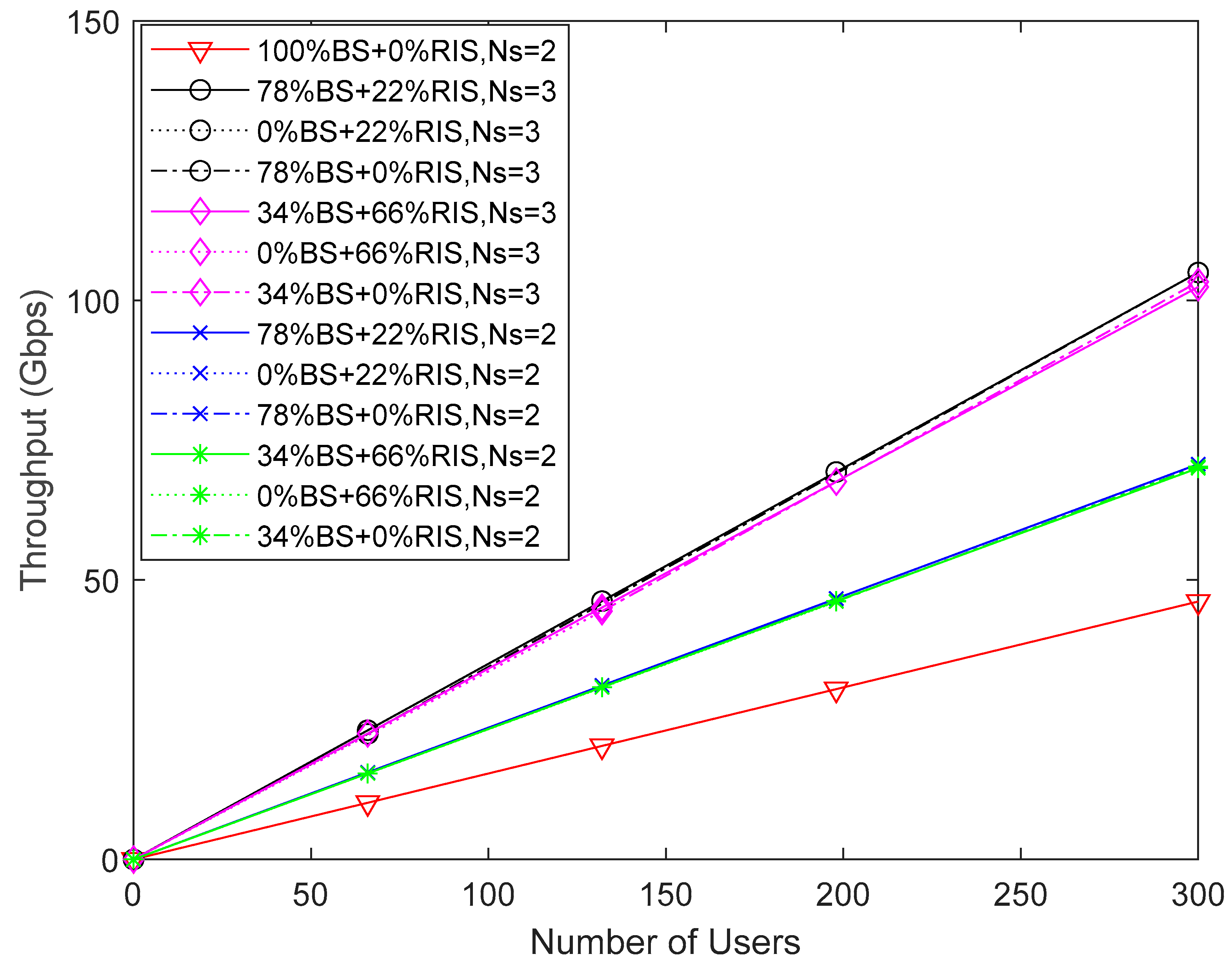
In Figure 10, it is shown the throughput performance versus number of users in the Stadium scenario. The throughput curves of Figure 10 were obtained with a maximum transmitted power of 250 mW. We keep the maximum number of subcarriers of 3300 to avoid intra cell (sector) interference. When we consider 11 PRB per user, i.e., Nc=132 the maximum number of users per sector is 3300/132=25. In the scenario there are 12 sectors, 4 BS each one with 3 sectors. The total number of served users at the same time in the Stadium is 25x12=300. Two different RIS sizes appear since each RIS panel is divided into sub-panels when serving more than 1 user. We have NRIS=192 and 576 elements. When users are served with a direct link only from BS (100%BS+0%RIS), we have a total average throughput of approximately 48 Gbps for 300 users (represented as a red line). In the Stadium there are 22x3=66 RIS panels and 4x3=12 TRPs. Considering the black and blue lines, when users at cell borders start to be served by RIS panels, 66 users from 300 (i.e., 66/300=0.22) must be subtracted resulting in 300-66=234 users (i.e., 234/300=0.78) are served by 12 TRPs, 78%BS+22%RIS. For the pink and green lines, when 66x3=198 users are served by RIS 198/300=0.66, the remaining 300-198=102 users (i.e., 102/300=0.34) are served by TRPs, 34%BS+66%RIS. We observe that the throughput gain of curves with Ns=3 compared to Ns=2, is 1.5. There is no difference of throughput in users served by RIS (0%BS) compared to users served by BS (0%RIS). If more users are served by RIS panels (66%RIS) there is a throughput decrease compared to curves with few users (22%RIS) that is only noticeable for Ns=3 (curves black and pink). For Ns=2 there is no decrease of throughput when more users are served by the same RIS panel (curves blue and green). Note that in all curves there is no decrease of throughput for increasing Nu because C-RAN operation combines transmitted signal power to RIS and BS, decreasing substantially inter cell interference. We are also assuming perfect CSI in link level results and there is no intra cell interference as explained above.
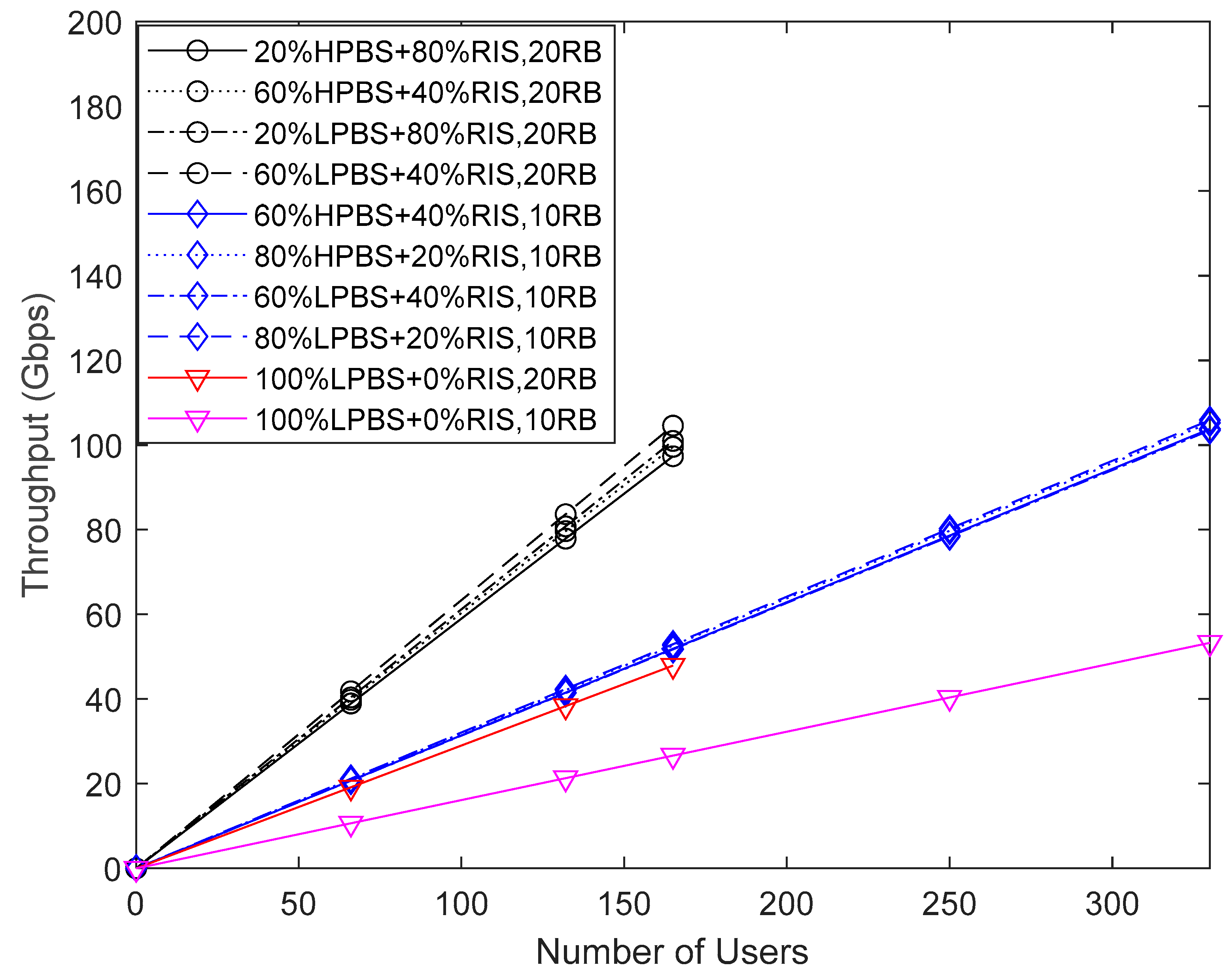
In Figure 11, it is also shown the throughput performance versus Nu in the Stadium scenario, with two different maximum transmitted powers from BSs. Low Power BSs (LPBS) transmit 250 mW and High Power BSs (HPBS) transmit 3.16W. We keep the maximum number of subcarriers of 3300 to avoid intra sector interference. Assigning 10 PRB per user, i.e., Nc=120, and for 20 PRB per user, Nc=240. With 10 PRB to each user, 3300/120=27.5 is the number of users per sector. The total number of served users at the same time in the Stadium is 27.5x12=330. With 20 PRB to each user, there are 3300/240=13.75 users per sector. The total number of served users at the same time in the Stadium is 13.75x12=165. When users are exclusively served by the TRPs of BS with direct links 100%BS+0%RIS, we have a total throughput of approximately 53 Gbps for 330 users (pink line), and a total throughput of 48 Gbps for 165 users (red line). Considering the case of 10 PRBs (blue lines), when 66 users at cell borders are served by RIS (i.e., 66/330=0.20), then the remaining 330-66=264 users are served by TRPs, (i.e., 264/330=0.80), 80%BS+20%RIS,10RB. When 66x2=132 users are served by RIS (i.e., 132/330=0.40), the remaining 60% users are served by TRP 60%BS+40%RIS,10RB. Assigning 20 PRB per user (black lines), when 66 users at cell borders are served by RIS (i.e., 66/165=0.40), then 165-66=99 users are served by TRPs, 99/165=0.60, 60%BS+40%RIS,20RB. When 66x2=132 users are served by RIS (i.e., 132/165=0.80), then the remaining 165-132=33 users, (i.e., 33/132=0.20) are served by TRP 20%BS+80%RIS,20RB. We observed only a very slight decrease of the throughput results by increasing the number of users from 1 to 2 served by every RIS panel. There is almost no difference in achieved throughput between HPBS and LPBS. There is a slightly higher throughput for LPBS that is more noticeable for 20 RB. Throughput gains are between 97% for 10RB and 110% for 10RB.
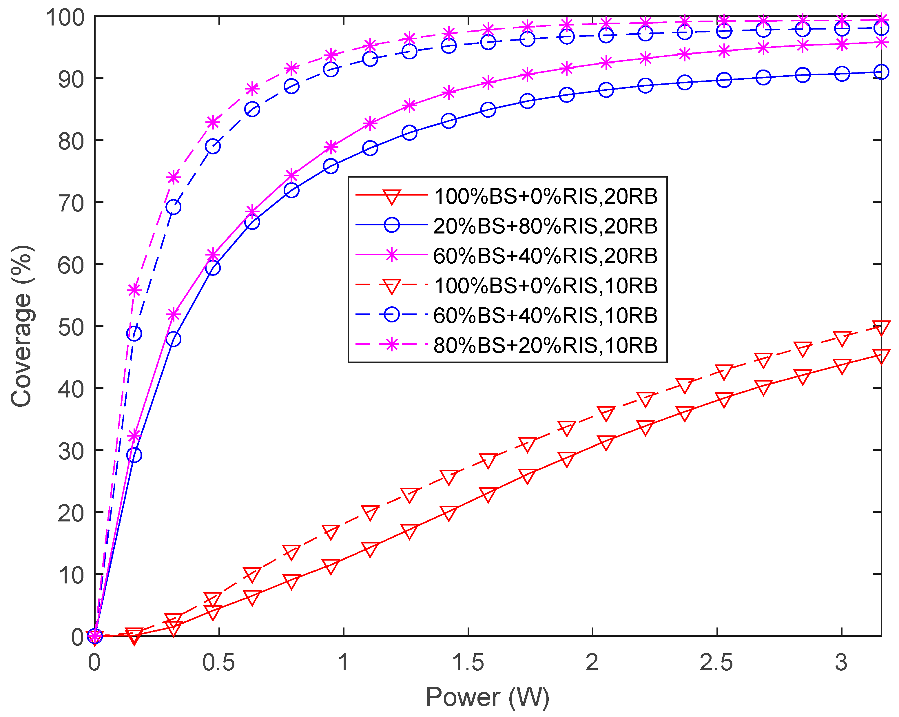
Figure 12 illustrates the average coverage versus transmitted power for both Nc=120 (10 PRB) and Nc=240 (20 PRB), corresponding to the throughput performance presented in Figure 11 considering only HPBS, with a maximum transmitted power of 3.16 W (35dBm). The comparison between Figure 12 and Figure 11 indicates that there is a direct correspondence between the throughput performance of Figure 11 and the associated coverage of Figure 12. However, in terms of coverage the differences are more noticeable than with throughput. It is noticeable that for the maximum transmitted power, the highest coverage of 99.4% is achieved by the curve 80%BS+20%RIS,10RB followed by the curve 60%BS+40%RIS,10RB. Next follow the curves 60%BS+40%RIS,20RB and 20%BS+80%RIS,20RB. It is obvious that when the number of PRBs per user doubles the coverage decreases. It is also noticeable that doubling the number of users served by RIS panels also decreases the coverage. The lowest coverage values correspond to no RIS panels activated, i.e., 100%BS+0%RIS, 10RB and finally 100%BS+0%RIS,20RB with a coverage of 45.4%. The coverage gain compared to the highest coverage value with 20RB is 111% and 98% for 10RB.
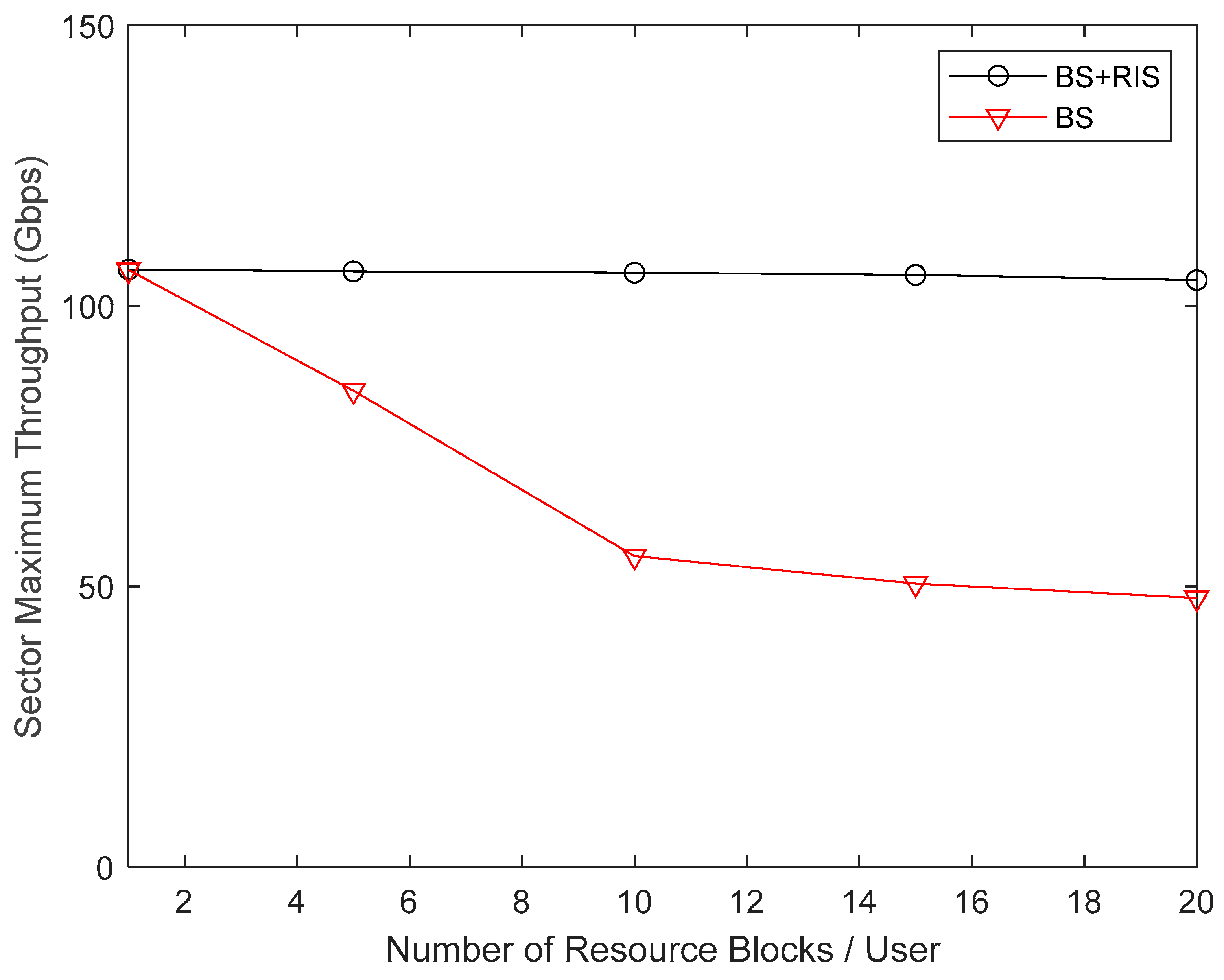
In Figure 13, we consider again the Stadium scenario, presenting the aggregate throughput for each sector, considering the maximum transmit power of 24 dBm, versus the number of PRBs per user. The maximum number of subcarriers is set as 3300 per sector independently of the number of PRBs per user. We evaluate the sector throughput only for some specific number of PRBs, namely, 1PRB, 5PRB, 10PRB, 15PRB and 20PRB. Assigning 1 PRB per user corresponds to Nc=12, 5 PRB per user corresponds to Nc=60, 10 PRB per user corresponds to Nc=120, 15 PRB per user corresponds to Nc=180 and finally 20 PRB per user requires Nc=240 subcarriers. The number of users per sector when each user has 1 PRB is 3300/12=275. In total, there are 12 sectors in the Stadium, thus a total of 3300 active users. For the case where every active user has 20 PRB then there are 3300/240=13.75 users per sector and the total of active users in the Stadium is 165. We observe in Figure 13 that for the curve BS (100%BS+0%RIS) there is a maximum throughput for 1 PRB, which is the same for the curve BS+RIS. For 5 PRB and 10 PRB per user there is a clear linear decrease of throughput of the red curve (BS) compared to black curve BS+RIS. The decrease of throughput continues with 15 PRB and 20 PRB but in a slower way. The curve BS+RIS has almost the same aggregate throughput per sector, however, it is noticeable a very slight decrease with increasing number of PRBs. When users are transmitting a higher number of PRBs the size of packets transmitted is higher and more likely to suffer deep fades. In this case, the link diversity RIS+BS provided by the C-RAN is able to cope with the expected decrease of throughput.
The third evaluated scenario is the Indoor Factory, which is the only one with a higher frequency band at sub-THz. The system operates at 100 GHz which, due to its shorter wavelength, allows us to work with more elements at the RIS, i.e., NRIS=576 up to 2304. The maximum transmit power of BS is 30 mW (14.8dBm). Users are placed uniformly around 2 sites with TRPs equipped with UPA antennas per sector, localized 75 meters close to the walls of the Indoor Factory (see Figure 5 and Table 3). We have considered high density clutter inside the Factory, with low BS antenna height and high BS antenna height. For this scenario we keep 5G NR numerology 3, with Δf=120KHz, a bandwidth of 400MHz and 112 symbols transmitted in every millisecond, such as in the Stadium scenario. Thus, it is possible to compare directly the two scenarios in spite of having different frequency bands and areas. In all simulations in the Factory environment, each transmitting TRP has a UPA with Ntx= 256 antennas, and the user receiver side, has Nrx= 16. Different numbers of transmitted symbols per subcarrier were considered in the simulations and Ns=3. When there are no active RIS panels in the Factory there are only 2 BS, each with 3 sectors, making a total of 6 sectors. In this case, users are uniformly distributed within a radius of 70 m (see Table 3). When simulating performance curves with BSs and RIS operating simultaneously, users that are connected to BSs will be uniformly distributed within a radius of 50 m. 16 RIS panels are uniformly distributed inside the scenario and users served by them are distributed within a radius of 25 m.
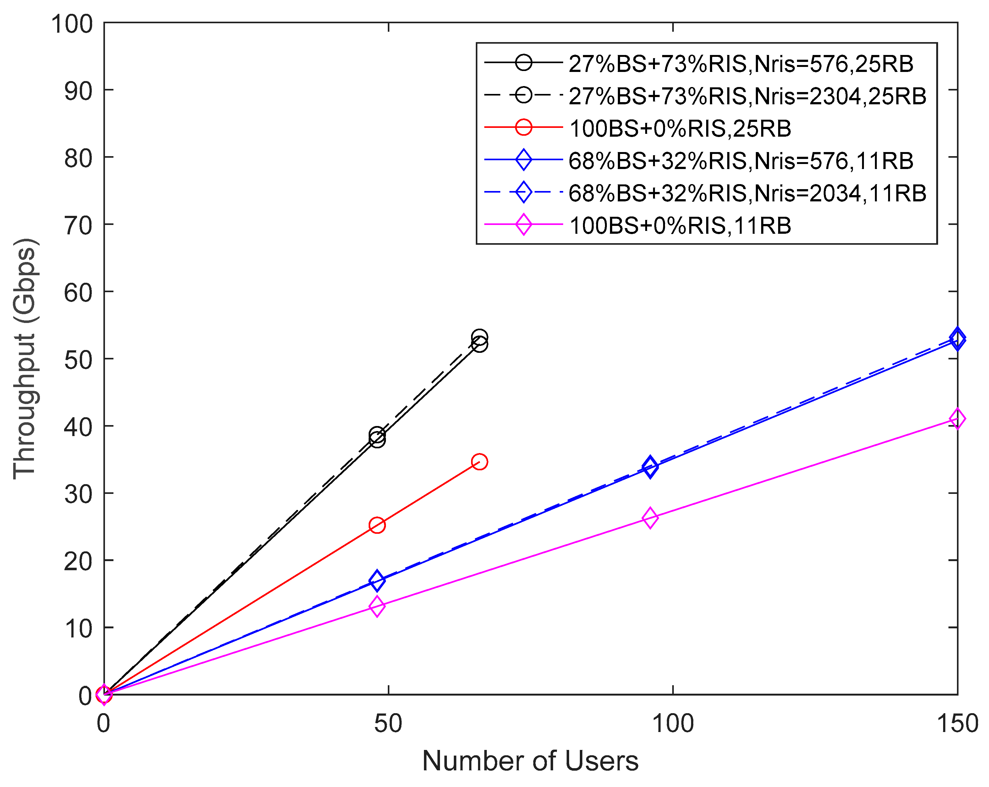
In Figure 14, it is shown the throughput performance versus Nu in the Factory scenario, with low BS antenna height, for two different resource blocks, and RIS panels. The scenario parameters are Ntx = 256, Nrx = 16, Ns = 3. An assignment of 11 PRB per user, gives Nc=132, and 25 PRB per user, gives Nc=300. With 11 PRB per user, 3300/120=25 is the number of users per sector. With 25 PRB per user, 3300/3000=11 is the number of users per sector. As there are 6 sectors in the Factory, the total number of users is 150 or 66 for 11 PRB and 25 PRB, respectively. When users are exclusively served by the TRPs of BS with direct links 100%BS+0%RIS, we have a total throughput of approximately 41 Gbps for 150 users (pink line), and the total throughput of 37 Gbps for 66 users (red line). In the Factory there are 16x3=48 RIS panels and 2x3=6 TRPs (one per sector). When users at cell borders start to be served by RIS panels, 48 users must be subtracted resulting in 150-48=102 users served by 6 TRPs. The 48 users are served by RIS 48/150=0.32 (blue lines), and the remaining 68% users are served by TRPs 68%BS+32%RIS,11RB. In the case of 25 PRB (black lines) the total number of users is 66, we have 48 users served by RIS (i.e., 48/66=0.73) and the remaining 66-48=18 users served by TRPs (i.e.,18/66=0.27), 27%BS+73%RIS,25RB. We observe that by increasing the number of RIS panels from 576 up to 2304 only increases slightly the throughput. This increment is more noticeable for 25RB. For the case of maximum number of users there is almost no difference in the achieved throughput between lines 27%BS+73%,25RB and 68%BS+32%RIS,11RB. When compared to lines 100%BS+0%RIS, the throughput gains are between 29% for 11 PRB and 53% for 25 PRB.
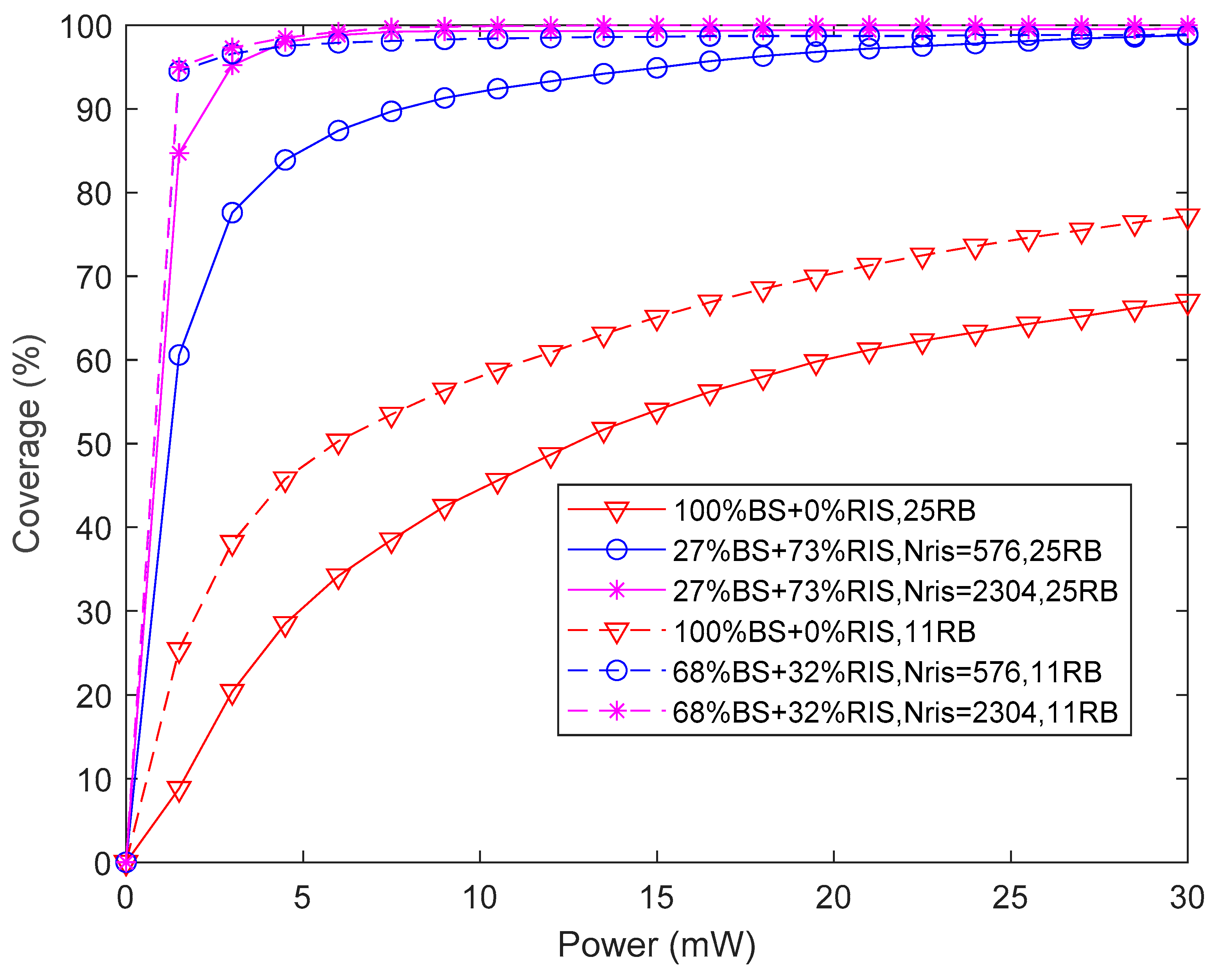
Figure 15 presents the average coverage versus transmitted power for both Nc=132 (11 PRB) and Nc=300 (25 PRB), with maximum transmitted power of 30 mW (14.8dBm), corresponding to the throughput performance illustrated in Figure 14. As expected, there is a direct correspondence between the throughput performance of Figure 14 and the associated coverage of Figure 15. In terms of performance of coverage, the differences between 11 PRB, or 25 PRB per user are higher than with throughput. We observe that for 11 PRBs with the maximum transmitted power, the highest coverage of 99% is achieved for both 576 and 2304 RIS panels. However, the coverage for 25 PRBs per user is higher when the RIS panels have 2304 elements compared to 576 elements, not only for 30 mW but also for all transmitted power interval. The lowest coverage values are 67% and 77% corresponding both to no activated RIS panels, i.e., 100%BS+0%RIS,25RB and 100%BS+0%RIS,11RB, respectively. The corresponding coverage gains are between 29% for 11 PRB and 48% for 25 PRB. This is in accordance with throughput values of Figure 13. The comparison of the average coverage of Factory scenario (Figure 15) is slightly higher than the coverage of Stadium scenario (Figure 12).
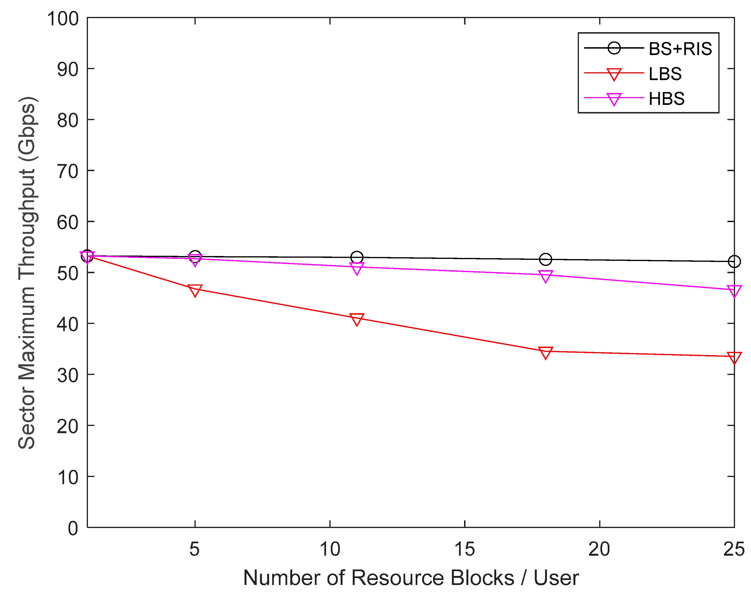
In Figure 16, we consider the Factory scenario, illustrating the aggregate throughput for each sector, versus the number of PRBs per user, considering the maximum transmit power of 14.8 dBm. We evaluate the sector throughput for some specific number of PRB, namely, 1PRB, 5PRB, 11PRB, 18PRB and 25PRB. With 1 PRB per user results Nc=12, with 5 PRB per user results Nc=60, with 11 PRB per user results Nc=132, with 18 PRB per user results Nc=216 and finally 25 PRB per user requires Nc=300 subcarriers. The number of users per sector when each user has 1 PRB is 3300/12=275. In total, there are 6 sectors in the Stadium, thus there is a maximum of 1650 active users. For the case where every active user has 25 PRB then there are 3300/300=11 users per sector and the total number of active users in the Factory is 66. We observe in Figure 15 that for the red curve LBS (100%BS+0%RIS) where the BS UPA antenna is at 2 m height, there is a maximum throughput for 1 PRB, which is the same for both curves BS+RIS (black) and HBS (pink). For 5 PRB, 11 PRB, 18 PRB per user there is a clear linear decrease of throughput of the red curve compared to the black curve BS+RIS that has almost the same constant throughput. The decrease in throughput continues with 25 PRB but in a slower way. The pink curve HBS with the BS UPA antenna at 8 m height has also a decreasing aggregate throughput per sector, for an increasing number of PRBs. However, it is a very slight decrease with the increasing number of PRB. When users are served by BS at 8 m height there is almost no interference from the high clutter density because the height of clutter is 6 m. The reason why transmitting higher number of PRBs per user decreases the throughput has to do with packets of large size that are more likely to suffer deep fades. The link diversity of RIS+BS is provided by the C-RAN operation that is capable to avoid the decrease of throughput. Therefore, if possible the antennas of BS should be placed as high as possible to be above the height of high clutter density characteristic of Indoor Factory scenarios.
The comparison of Figure 16 with Figure 13 indicates that the aggregate throughput of each sector of the Factory is half of the throughput of the Stadium. This is explained by the number of BSs being half in the Factory compared to the Stadium. Therefore, if we need to increase the aggregate throughput of the Factory scenario, we have two options, such as 1) We increase the number of BS or 2) We use carrier aggregation. Indeed, 5G NR allows for aggregation of 16 carriers each one with 400 MHz. At 100 GHz it is possible to have available a total bandwidth of 6.4 GHz. The first solution involves densification of the network, and it is not possible to be energy efficient with this solution. To be energy efficient and achieve high sector throughput we need to aggregate carriers and place RIS surfaces distributed around the BSs of the scenario.
5. Conclusions

RISs are considered a key technology for future wireless networks, in particular for B5G and 6G systems. In this article, we present an approach to increase the energy efficiency of future networks by replacing BS with RIS panels considering multi-stream multiple-input multiple output (MIMO) orthogonal frequency division multiplexing (OFDM) links. We perform system-level assessments of RIS-aided B5G C-RAN scenarios operating at 3.6 GHz, mmWave (28 GHz) and sub-THz (100 GHz) bands. We have only considered scenarios where the communication for/from different users is based on orthogonal multiple access, avoiding intra cell interference.
We have addressed smart radio environments, increasing their capacity, as for example, the number of active IoT devices of a Smart City scenario, in 3.6 GHz and 28 GHz. The minimum number of active users in the Smart City environment depends on the coherence interval of the scenario because of the need for orthogonal reference pilots in the uplink. We considered 19800 transmitting devices each one with 1 subcarrier per subframe of 1 millisecond duration. The use of a C-RAN allows for decreasing the pilot pollution between sectors because of its operation mode. The introduction of RIS elements at 28 GHz in this scenario was able to increase the coverage of low power and low rate IoT devices located at cell borders. The coverage gain was about 7%.
In the other smart scenarios evaluated, namely, outdoor/ indoor Stadium with Pitch at 28 GHz and Indoor Factory at 100 GHz we studied the improvement in terms of coverage and throughput.
The maximum number of evaluated active users in the Stadium w/ Pitch was 3300, transmitting one PRB with 12 subcarriers each. We have evaluated the effect of variation of BS transmit power, from 24 dBm up to 35 dBm concluding that the performance results are almost constant. The introduction of C-RAN. in spite of its higher computing complexity. allowed for decreasing inter cell interference between sectors. Throughput and coverage gains between 97% and 110% were observed with the introduction of RIS at cell borders of the BS in the Stadium turf and stands. However, the throughput and coverage gains depend on the number of PRBs per user. The gains are higher when increasing the number of PRB per user.
The maximum number of active users in the Indoor Factory was 1650 assuming that one PRB per user was transmitted. We have evaluated different numbers of RIS elements, from 576 up to 2304, concluding that the difference of performance is small. However, for an increasing number of PRB per user, the higher performance of RIS with 2304 elements was noticeable. Throughput and coverage gains are between 29% and 50%, depending on the number of PRB per user. To increase throughput the antennas of BS should be placed higher than the height of clutter density of the Factory. We proposed the use of carrier aggregation of up to 16 carriers, each one with 400 MHz, in order to increase the throughput in this scenario at 100 GHz.
As future work we intend to apply new semi deterministic path loss models, capable of predicting with high accuracy the path loss in scenarios with more obstructions and irregular layouts of factories at 300 GHz (THz band) to evaluate the coverage and throughput performance, with system level simulations.

Author Contributions

Conceptualization, V.V., J.P.P., N.S. and A.C.; methodology, V.V., J.P.P., N.S. and A.C.; software, V.V., J.P.P., N.S. and A.C; validation, V.V., J.P.P., N.S. and A.C.; formal analysis, V.V., J.P.P., N.S., and A.C.; investigation, V.V., J.P.P., N.S., M.M.S. and A.C.; resources, A.C. and N.S.; data curation, V.V., J.P.P., N.S. and A.C.; writing—original draft preparation, V.V., J.P.P., N.S., M.M.S. and A.C.; writing—review and editing, V.V., J.P.P., M.M.S., N.S., P.S. and A.C.; visualization, V.V., J.P.P., N.S. and A.C.; supervision, A.C. and N.S.; project administration, A.C. and N.S.; funding acquisition, A.C., N.S. and M.M.S. All authors have read and agreed to the published version of the manuscript.

Funding

The authors acknowledge the funding provided by FCT/MCTES through national funds and when applicable co-funded EU funds under the project UIDB/50008/2020.

Institutional Review Board Statement

Not applicable.

Informed Consent Statement

Not applicable.

Data Availability Statement

The data presented in this study are available on request from the corresponding author. The data are not publicly available due to privacy.

Conflicts of Interest

The authors declare no conflict of interest.

References

  1. Wong, V.W. Key Technologies for 5G Wireless Systems; Cambridge University Press: Cambridge, UK, 2017; ISBN 9781107172418. [Google Scholar]
  2. 3rd Generation Partnership Project (3GPP). TS 38.101 v14.1.1, 5GNR. User Equipment (UE) radio transmission and reception, Release 15, August 2017. Available online: https://3gpp.org/ftp/Specs/archive/38_series/38.101-1/38101-1-001.zip (accessed on 24 January 2022).
  3. da Silva, M.M.; Dinis, R. Power-Ordered NOMA with Massive MIMO for 5G Systems. Appl. Sci. 2021, 11, 3541. [Google Scholar] [CrossRef]
  4. Mihovska, A.; Prasad, R. Overview of 5G New Radio and Carrier Aggregation: 5G and Beyond Networks. In Proceedings of the 2020 23rd International Symposium on Wireless Personal Multimedia Communications (WPMC), Okayama, Japan, 19–26 October 2020; pp. 1–6. [Google Scholar]
  5. Farris, I.; Taleb, T.; Khettab, Y.; Song, J.S. A Survey on Emerging SDN and NFV Security Mechanisms for IoT Systems. IEEE Commun. Surv. Tutorials 2018, 21, 812–837. [Google Scholar] [CrossRef]
  6. Xu, L.D.; He, W.; Li, S. Internet of Things in Industries: A Survey. IEEE Trans. Ind. Inform. 2014, 10, 2233–2243. [Google Scholar] [CrossRef]
  7. Brundu, F.G.; Patti, E.; Osello, A.; Del Giudice, M.; Rapetti, N.; Krylovskiy, A.; Jahn, M.; Verda, V.; Guelpa, E.; Rietto, L.; et al. IoT Software Infrastructure for Energy Management and Simulation in Smart Cities. IEEE Trans. Ind. Informatics 2017, 13, 832–840. [Google Scholar] [CrossRef]
  8. Lee, B.M.; Yang, H. Massive MIMO for Industrial Internet of Things in Cyber-Physical Systems. IEEE Trans. Ind. Informatics 2018, 14, 2641–2652. [Google Scholar] [CrossRef]
  9. Lee, B.M.; Yang, H. Massive MIMO with Massive Connectivity for Industrial Internet of Things. IEEE Trans. Ind. Electron. 2020, 67, 5187–5196. [Google Scholar] [CrossRef]
  10. Bjornson, E.; Wymeersch, H.; Matthiesen, B.; Popovski, P.; Sanguinetti, L.; de Carvalho, E. Reconfigurable Intelligent Surfaces: A signal processing perspective with wireless applications. IEEE Signal Process. Mag. 2022, 39, 135–158. [Google Scholar] [CrossRef]
  11. Yang, F.; Pitchappa, P.; Wang, N. Terahertz Reconfigurable Intelligent Surfaces (RISs) for 6G Communication Links. Micromachines 2022, 13, 285. [Google Scholar] [CrossRef] [PubMed]
  12. Zaidi, S.; Ben Smida, O.; Affes, S.; Vilaipornsawai, U.; Zhang, L.; Zhu, P. User-Centric Base-Station Wireless Access Virtualization for Future 5G Networks. IEEE Trans. Commun. 2019, 67, 5190–5202. [Google Scholar] [CrossRef]
  13. 3rd Generation Partnership Project (3GPP). TR 38.913 5G.; Study on scenarios and requirements for next generation access technologies, version 16.0.0 Release 16, July 2020. Available online: https://3gpp.org/ftp/Specs/archive/38_series/38.913/38913-g00.zip.
  14. 3rd Generation Partnership Project (3GPP). TR 38.901 Study on channel model for frequencies from 0.5 to 100 GHz, version 16.1.0, Release 16, November 2020. Available online: https://3gpp.org/ftp/Specs/archive/38_series/38.901/38901-e20.zip.
  15. 3rd Generation Partnership Project (3GPP). TS 38.211 v15.2.0. 5G/NR Physical Channels and Modulation, (Release 15), 2018. Available online: https://3gpp.org/ftp/Specs/archive/38_series/38.211/38211-f30.zip.
  16. 3rd Generation Partnership Project (3GPP). TS 38.214; NR.; Physical layer procedures for data, (Release 15), 2020. Available online: https://3gpp.org/ftp/Specs/archive/38_series/38.214/38214-fb0.zip.
  17. 3rd Generation Partnership Project (3GPP). TS 38.213; NR.; Physical layer procedures for control, (Release 15), 2020. Available online: https://3gpp.org/ftp/Specs/archive/38_series/38.213/38213-fb0.zip.
  18. Zaidi, A.A.; Baldemair, R.; Tullberg, H.; Bjorkegren, H.; Sundstrom, L.; Medbo, J.; Kilinc, C.; Da Silva, I. Waveform and Numerology to Support 5G Services and Requirements. IEEE Commun. Mag. 2016, 54, 90–98. [Google Scholar] [CrossRef]
  19. Begishev, V.; Samuylov, A.; Moltchanov, D.; Machnev, E.; Koucheryavy, Y.; Samouylov, K. Connectivity Properties of Vehicles in Street Deployment of 3GPP NR Systems. In Proceeding of the 2018 IEEE Globecom Workshops (GC Wkshps), Abu Dhabi, United Arab Emirates, 9–13 December 2018; pp. 1–7. [Google Scholar]
  20. Gkonis, P.; Trakadas, P.; Kaklamani, D. A Comprehensive Study on Simulation Techniques for 5G Networks: State of the Art Results, Analysis, and Future Challenges. Electronics 2020, 9, 468. [Google Scholar] [CrossRef]
  21. ElMossallamy, M.A.; Zhang, H.; Song, L.; Seddik, K.G.; Han, Z.; Li, G.Y. Reconfigurable Intelligent Surfaces for Wireless Communications: Principles, Challenges, and Opportunities. IEEE Trans. Cogn. Commun. Netw. 2020, 6, 990–1002. [Google Scholar] [CrossRef]
  22. Praia, J.; Pavia, J.P.; Souto, N.; Ribeiro, M. Phase Shift Optimization Algorithm for Achievable Rate Maximization in Reconfigurable Intelligent Surface-Assisted THz Communications. Electronics 2021, 11, 18. [Google Scholar] [CrossRef]
  23. Zhang, S.; Zhang, R. Capacity Characterization for Intelligent Reflecting Surface Aided MIMO Communication. IEEE J. Sel. Areas Commun. 2020, 38, 1823–1838. [Google Scholar] [CrossRef]
  24. Huang, C.; Alexandropoulos, G.C.; Zappone, A.; Debbah, M.; Yuen, C. Energy Efficient Multi-User MISO Communication Using Low Resolution Large Intelligent Surfaces. 2018 IEEE Globecom Workshops (GC Wkshps) 2018, 1–6. [Google Scholar] [CrossRef]
  25. Mu, X.; Liu, Y.; Guo, L.; Lin, J.; Al-Dhahir, N. Capacity and Optimal Resource Allocation for IRS-Assisted Multi-User Communication Systems. IEEE Trans. Commun. 2021, 69, 3771–3786. [Google Scholar] [CrossRef]
  26. Pavia, J.P.; Velez, V.; Ferreira, R.; Souto, N.; Ribeiro, M.; Silva, J.; Dinis, R. Low Complexity Hybrid Precoding Designs for Multiuser mmWave/THz Ultra Massive MIMO Systems. Sensors 2021, 21, 6054. [Google Scholar] [CrossRef] [PubMed]
  27. Pei, X.; Yin, H.; Tan, L.; Cao, L.; Li, Z.; Wang, K.; Zhang, K.; Bjornson, E. RIS-Aided Wireless Communications: Prototyping, Adaptive Beamforming, and Indoor/Outdoor Field Trials. IEEE Trans. Commun. 2021, 69, 8627–8640. [Google Scholar] [CrossRef]
  28. Liu, S.; Ni, P.; Liu, R.; Liu, Y.; Li, M.; Liu, Q. BS-RIS-User Association and Beamforming Designs for RIS-aided Cellular Networks. 2021 IEEE/CIC International Conference on Communications in China (ICCC) 2021, 563–568. [Google Scholar] [CrossRef]
  29. Sihlbom, B.; Poulakis, M.I.; Di Renzo, M. Reconfigurable Intelligent Surfaces: Performance Assessment Through a System-Level Simulator. IEEE Wirel. Commun. 2022, 30, 98–106. [Google Scholar] [CrossRef]
  30. Gu, Q.; Wu, D.; Su, X.; Wang, H.; Cui, J.; Yuan, Y. System-level Simulation of Reconfigurable Intelligent Surface assisted Wireless Communications System. arXiv 2022, arXiv:2206.14777. [Google Scholar] [CrossRef]
  31. Velez, V.R.J.; Pavia, J.P.C.B.B.; Souto, N.M.B.; Sebastião, P.J.A.; Correia, A.M.C. Performance Assessment of a RIS-Empowered Post-5G/6G Network Operating at the mmWave/THz Bands. IEEE Access 2023, 11, 49625–49638. [Google Scholar] [CrossRef]
  32. Rappaport, T.S. Wireless Communications: Principles and Practice, 2nd ed.; Prentice-Hall: Englewood Cliffs, NJ, USA, 2002. [Google Scholar]
  33. Lee, B.M.; Yanghien, H. Massive MIMO With Massive Connectivity for Industrial Internet of Things. IEEE Trans. Ind. Electron. 2020, 67, 6. [Google Scholar] [CrossRef]
Figure 1. Illustration of a mMIMO communication system aided by RIS, consisting of BS, UE, and RIS with Nris reflecting elements.
Preprints 92039 g001
Figure 2. C-RAN illustration.
Preprints 92039 g002
Figure 3. Smart City scenario layout.
Preprints 92039 g003
Figure 4. Stadium with Pitch scenario layout: Micro layer: ISD = 36 m; 3 TRPs per micro cell.
Preprints 92039 g004
Figure 5. Indoor Factory scenario layout.
Preprints 92039 g005
Figure 6. BER versus distance for a scenario with fc=28GHz, Ntx=64, Ns=3, Nrx=16, Nris=144 or 576 elements with Nc=1.
Preprints 92039 g006
Figure 7. Throughput vs. number of devices for Smart City scenario with Ntx = 1, Ptx = 10dBm, for carrier frequencies of 3.6GHz and 28GHz.
Preprints 92039 g007
Figure 8. Throughput vs. number of devices for Smart City scenario with Ntx = 1, Ptx = 10dBm, for carrier frequency of 28GHz, Nris = 576.
Preprints 92039 g008
Figure 9. Coverage vs. transmitted power for Smart City scenario with carrier frequency of 28GHz with Nu = 19800, Nris = 576.
Preprints 92039 g009
Figure 10. Throughput vs. number of users for Stadium with Pitch scenario, with 11 PRB, Ntx = 64, Nrx = 16, two different Nris = 576 (22%RIS), Nris = 192 (66%RIS) and Ptx=24dBm.
Preprints 92039 g010
Figure 11. Throughput vs. number of users for Stadium with Pitch scenario, for two different number of resource blocks, LPBS with BS Power 24dBm and HPBS with 35dBm, Ns = 3, Ntx = 64, Nrx = 16, Nris = 576 and Nris = 288.
Preprints 92039 g011
Figure 12. Coverage vs. transmit power for Stadium with Pitch scenario, for two different number of resource blocks, HPBS transmit power (35dBm), Ntx = 64, Nrx = 16, Nris = 576.
Preprints 92039 g012
Figure 13. Throughput vs. number of resource blocks, for Stadium scenario, maximum load sector, Ns = 3, Ntx = 64, Nrx = 16, Nris= 576. LPBS transmit power (24dBm),
Preprints 92039 g013
Figure 14. Throughput vs. number of users, for Factory scenario, for two different resource blocks, and RIS panels. Ntx = 256, Nrx = 16, Ns = 3 (low BS antenna height and Ptx=30mW).
Preprints 92039 g014
Figure 15. Coverage vs. transmit power, for Factory scenario, for Ntx = 256, Nrx = 16, two different number of resource blocks and number of RIS panels.
Preprints 92039 g015
Figure 16. Throughput vs. number of resource blocks per user, for Factory scenario (LBS with BS antenna height 2 m, HBS with BS antenna height 8 m, Maximum sector load, Ntx = 256, Nrx = 16 and Nris = 2304).
Preprints 92039 g016
Table 1. Parameters of Smart City Scenario.
Parameters Smart City @ 3.6 Smart City @ 28
Area (m2) 660x550 m2 660x550 m2
Carrier Frequency 3.6 GHz 28 GHz
Cell Range w/o RIS 134 m 134 m
w/ RIS 100 m 100 m
Device mobility 0 km/h 0 km/h
Device distribution (horizontal) Uniform Uniform
Maximum active devices Up to 19800 Up to 19800
Transmit Power 10 dBm 10 dBm
Devices antenna gains 0 dBi 0 dBi
Area of RIS elements 1764 mm2 29.16 mm2
Table 2. Parameters of Stadium with Pitch Scenario.
Parameters Stadium stands Stadium turf
Area (m2) 168x126 m2 144x108 m2
Carrier Frequency 28 GHz 28 GHz
Cell Range w/o RIS 57 m 57 m
w/ RIS 34 m 34 m
User mobility 3 km/h 3 km/h
User distribution (horizontal) Uniform Uniform
Maximum UEs attached Up to 20923 Up to 18277
Transmit Power 35 dBm & 24 dBm 35dBm & 24 dBm
BS antenna gains 0 dBi 0 dBi
Area of RIS elements 29.16 mm2 29.16 mm2
Table 3. Parameters of Indoor Factory Scenario.
Parameters Factory w/ low BS Factory w/ high BS
Area (m2) 300x150 m2 300x150 m2
Carrier Frequency 100 GHz 100 GHz
Cell Range w/o RIS 70 m 70 m
w/ RIS 50 m 50 m
User mobility 3 km/h 3 km/h
User distribution (horizontal) Uniform Uniform
Maximum UEs attached Up to 19800 Up to 19800
Transmit Power 14.8 dBm 14.8 dBm
BS antenna gains 0 dBi 0 dBi
Area of RIS elements 2.25 mm2 2.25 mm2
Table 4. Additional Simulation Parameters for Smart City scenario.
Parameter Value
Coherence time Tc 50ms
Coherence band Bc 1.697MHz
Maximum time Tp 12.5ms
Maximum Nsc 79200
Max. active devices Nsc/4 19800
Number of sectors 12
Number of devices/sector 1650
Disclaimer/Publisher’s Note: The statements, opinions and data contained in all publications are solely those of the individual author(s) and contributor(s) and not of MDPI and/or the editor(s). MDPI and/or the editor(s) disclaim responsibility for any injury to people or property resulting from any ideas, methods, instructions or products referred to in the content.
Copyright: This open access article is published under a Creative Commons CC BY 4.0 license, which permit the free download, distribution, and reuse, provided that the author and preprint are cited in any reuse.
Prerpints.org logo

Preprints.org is a free preprint server supported by MDPI in Basel, Switzerland.

Subscribe

© 2024 MDPI (Basel, Switzerland) unless otherwise stated