Submitted:
01 December 2023
Posted:
04 December 2023
You are already at the latest version
Abstract
Keywords:
1. Introduction
2. Conventional Variant Apodization for Forward-Looking Sonar Imaging
2.1. Signal Model
2.2. Dual apodization and multi-apodization
3. Improved spatially variant apodization forward-looking sonar imaging method
3.1. SVA for two-dimensional forward-looking sonar imaging
3.2. Amplitude and phase error calibration
4. Simulation and Experimental Results
4.1. Simulation results
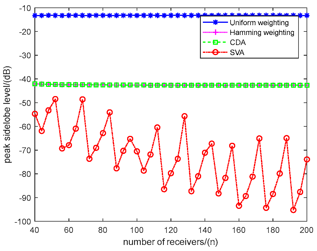
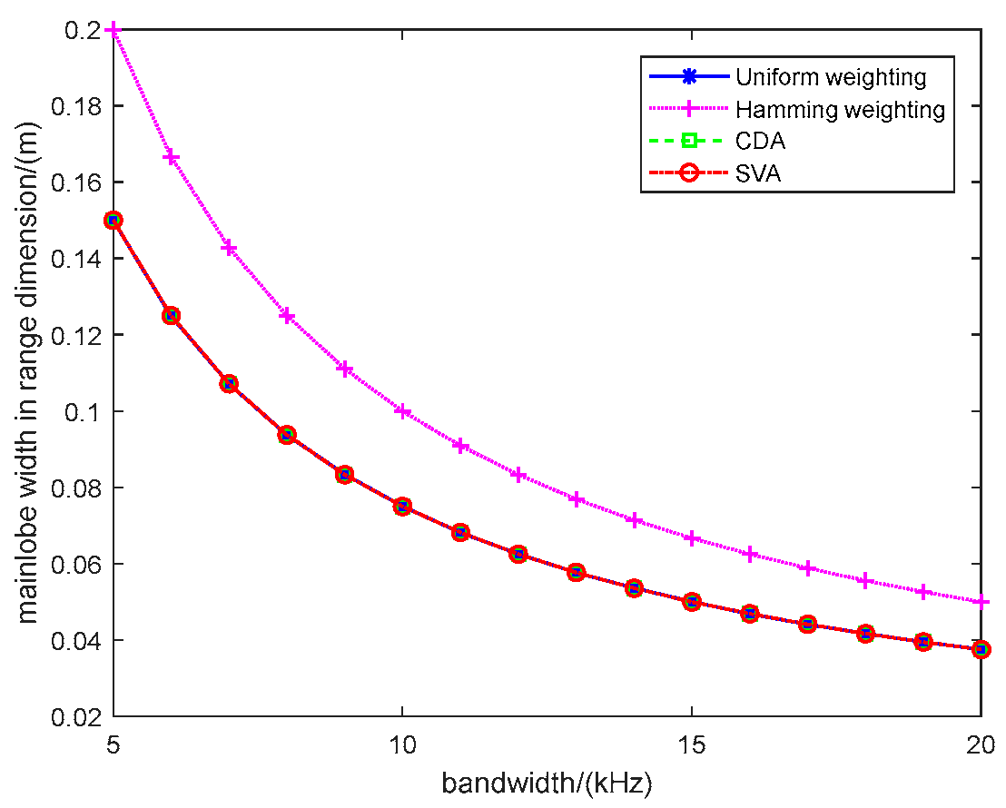
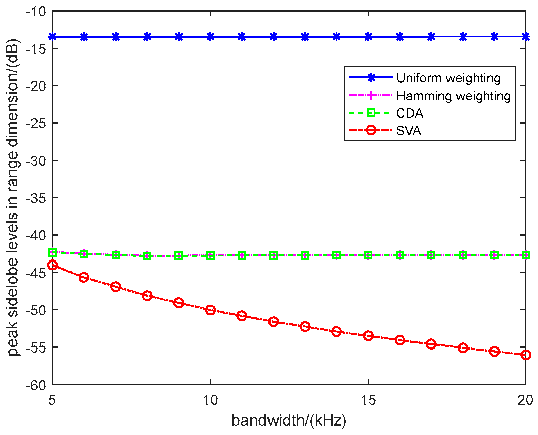
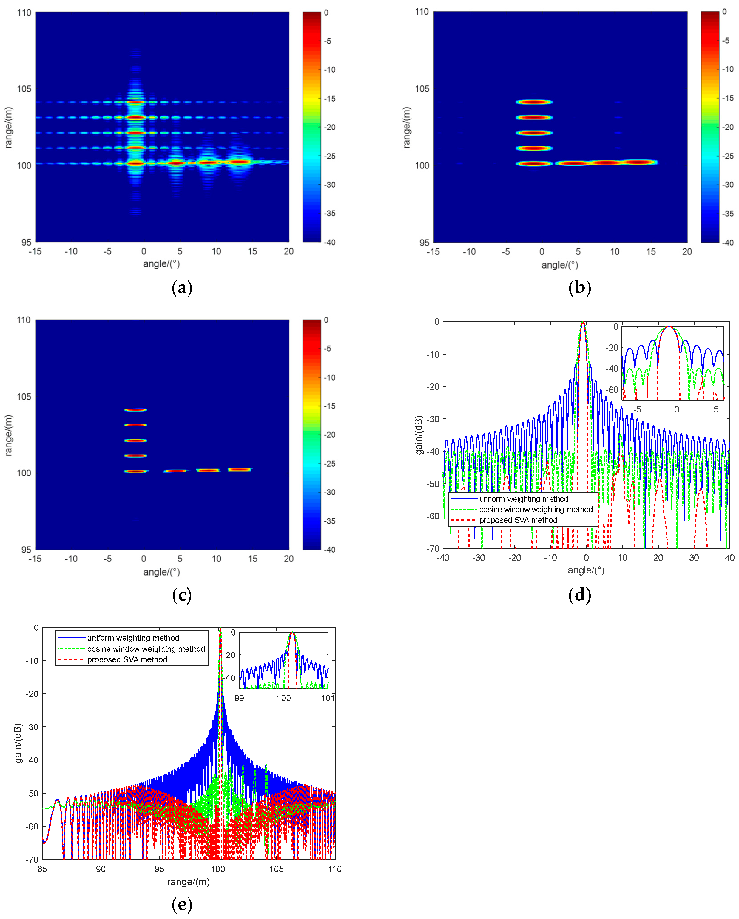
4.1.1. Analysis of the resolutions and sidelobes
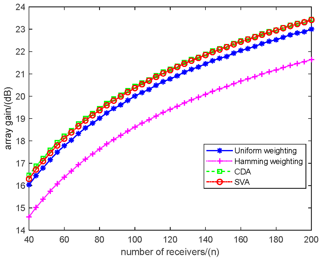
4.1.2. Analysis of the array gain
4.1.3. Analysis of the quality of sonar images
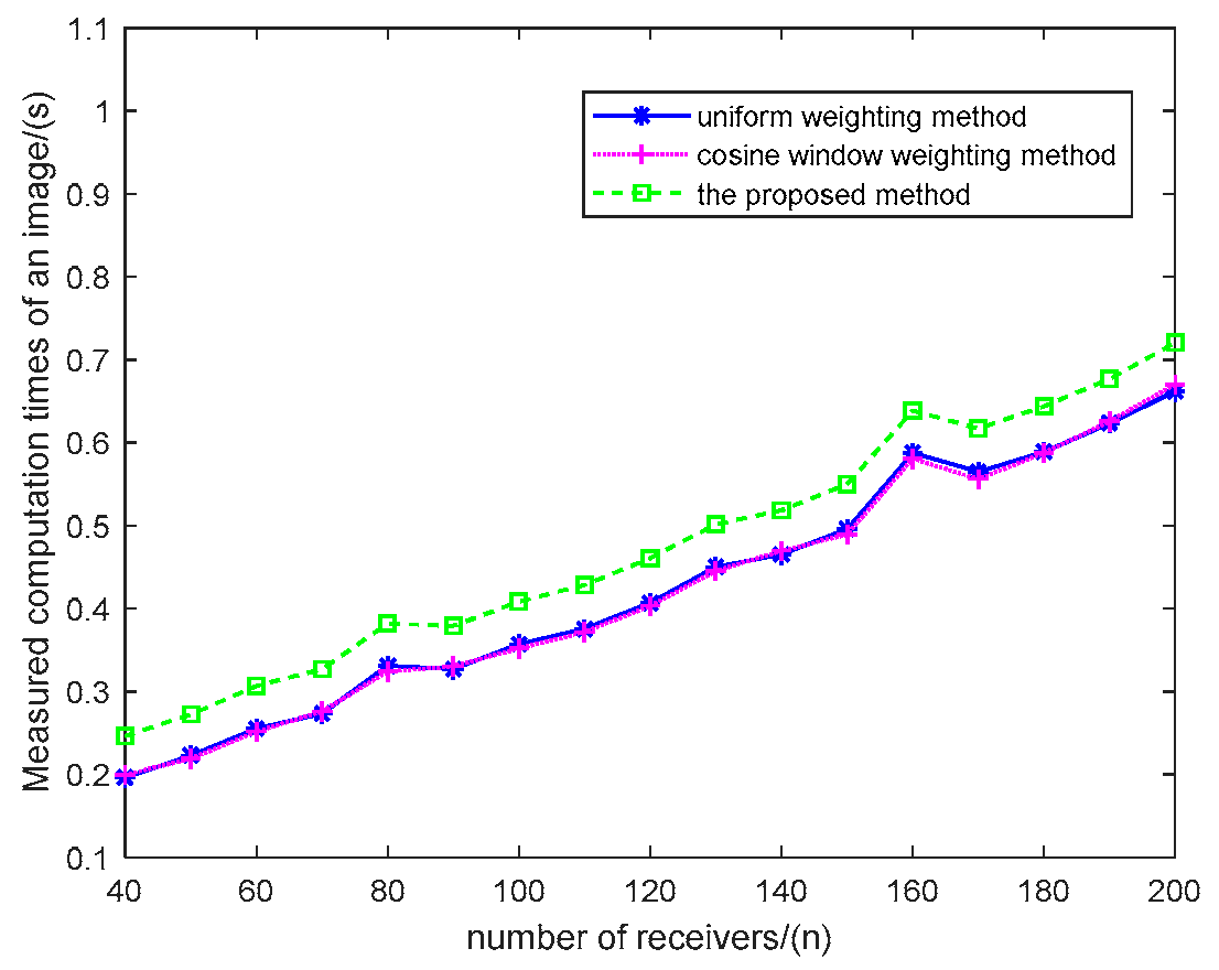
4.1.4. Analysis of the computation burden
4.1.5. Analysis of the robustness
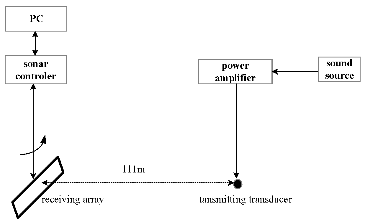
4.2. Lake experimental data processing results
4.2.1. Analysis of the array amplitude and phase error calibration
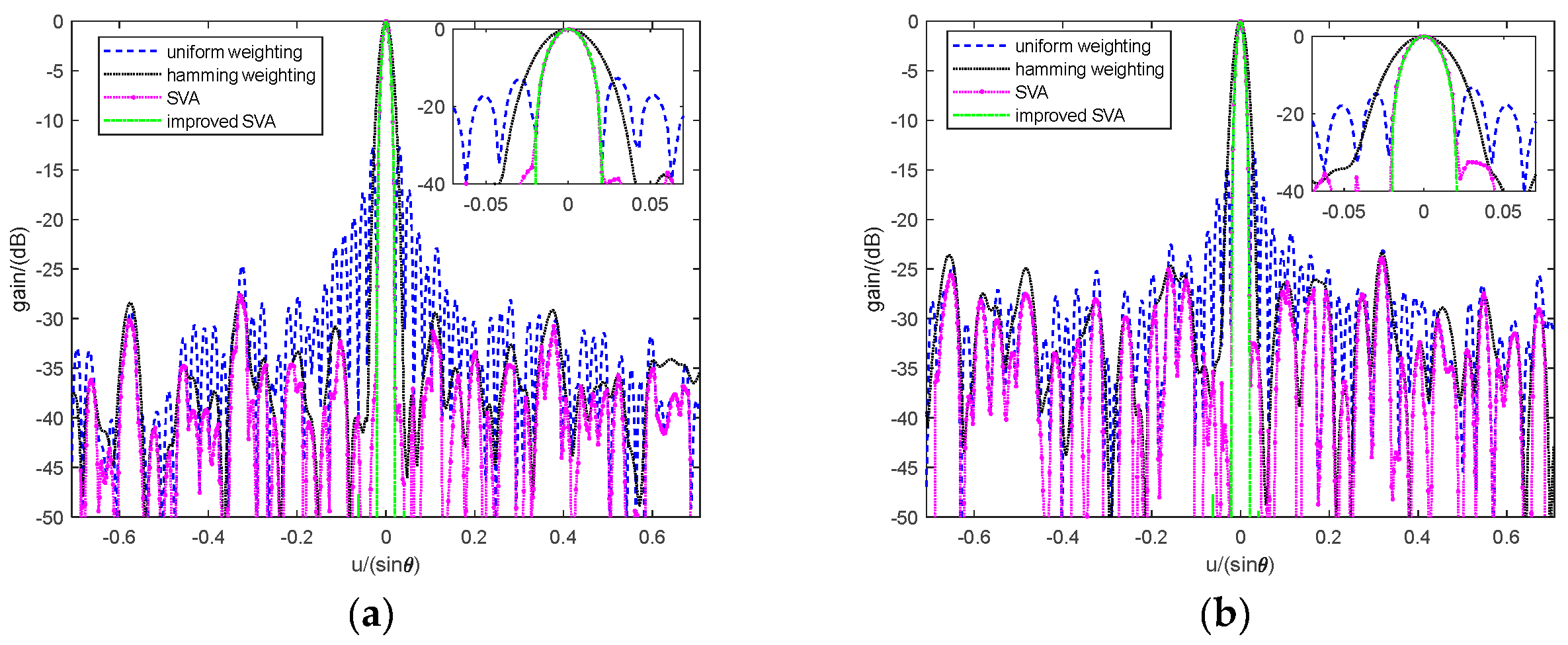
4.2.2. Improved SVA method for data processing and analysis
5. Conclusions
Author Contributions
Funding
Data Availability Statement
Conflicts of Interest
References
- Murino, V.; Trucco, A. Three-dimensional image generation and processing in underwater acoustic vision. Proc IEEE 2000. 2000, 88, 1903–1946. [Google Scholar] [CrossRef]
- Wang, S.; Wang, P.; Zhao, S.; et al. Feature-enhanced beamforming for underwater 3-D acoustic imaging. IEEE J. Ocean. Eng. 2023, 48, 401–415. [Google Scholar] [CrossRef]
- Petillot, Y.; Ruiz, T. I.; Lane, D.M. Underwater vehicle obstacle avoidance and path planning using a multi-beam forward looking sonar. IEEE J. Ocean. Eng. 2001, 26, 240–251. [Google Scholar] [CrossRef]
- Zhou, T.; Si, J.K.; Wang,L. Y.; et al. Automatic detection of underwater small targets using forward-looking sonar images. IEEE Trans. Geosci. Remote Sens. 2022, 60, 4207912. [Google Scholar]
- Kiang, C.W.; Kiang, J.F. . Imaging on underwater moving targets with multistatic synthetic aperture sonar. IEEE Trans. Geosci. Remote Sens. 2022, 60, 4211218. [Google Scholar] [CrossRef]
- Thomas C, W. A CFAR detection approach for identifying gas bubble seeps with multibeam echo sounders. IEEE J. Ocean. Eng. 2021, 46, 1346–1355. [Google Scholar]
- Liu, X.H.; Fan, J.H.; Sun, C.; et al. High-resolution and low-sidelobe forward-look sonar imaging using deconvolution. Appl.Acoust. 2021, 178, 107986. [Google Scholar] [CrossRef]
- Wang, P.; Chi, C.; Liu, J.Y.; et al. Improving performance of three-dimensional imaging sonars through deconvolution. Appl.Acoust. 2021, 175, 107812. [Google Scholar] [CrossRef]
- Van Trees, H.L. Optimum array processing: part 4 of detection, estimation, and modulation theory; John Wiley & Sons Inc.: New York, USA, 2002; pp. 17–79. [Google Scholar]
- Fredric J, H. On the use of windows for harmonic analysis with the discrete Fourier transform. Pro. IEEE 1978, 66, 51–83. [Google Scholar]
- Yan, L.; Piao, S.C.; Xu, F. Orthogonal waveform separation in multiple-input and multiple-output imaging sonar with fractional Fourier filtering. IET Radar, Sonar Navig. 2021, 15, 471–484. [Google Scholar] [CrossRef]
- Ma, C.; Sun, D.J.; Mei, J.D.; et al. Spatiotemporal two-dimensional deconvolution beam imaging technology. Appl. Acoust. 2021, 183, 108310. [Google Scholar] [CrossRef]
- Stoica, P.; Wang, Z.; Li, J. Robust Capon beamforming. IEEE Signal Process. Lett. 2003, 10, 172–175. [Google Scholar] [CrossRef]
- Lønmo, T.I.B.; Austeng, A.; Hansen, R.E. Improving swath sonar water column imagery and bathymetry with adaptive beamforming. IEEE J. Ocean. Eng. 2020, 45, 1552–1563. [Google Scholar] [CrossRef]
- Buskenes, J.I.; Hansen, R.E.; Austeng, A. Low-complexity adaptive sonar imaging. IEEE J. Ocean. Eng. 2017, 42, 87–96. [Google Scholar] [CrossRef]
- Blomberg, A.E.A. Adaptive beamforming for active sonar imaging; doctor, University of Oslo: Oslo, Norway, 2011. [Google Scholar]
- Liu, J.; Gershman, A.B.; Luo,Z. Q.; et al. Adaptive beamforming with sidelobe control: a second-order cone programming approach. IEEE Signal Process. Lett. 2015, 10, 331–334. [Google Scholar]
- Gerstoft, P.; Xenaki, A.; Mecklenbräuker, C.F. Multiple and single snapshot compressive beamforming. J. Acoust. Soc. Amer. 2015, 138, 2003–2014. [Google Scholar] [CrossRef] [PubMed]
- David, G.; Robert, J.I.; Zhang, B.; et al. Time domain compressive beam forming of ultrasound signals. J. Acoust. Soc. Amer. 2015, 137, 2773–2784. [Google Scholar] [CrossRef] [PubMed]
- Guo, Q.J.; Yang,S. Y.; Zhou, T.; et al. Underwater acoustic imaging via online bayesian compressive beamforming. IEEE Geosci. Remote Sens. Lett. 2022, 19, 4024505. [Google Scholar] [CrossRef]
- Guo, Q.J.; Xin, Z.N.; Zhou, T.; et al. Adaptive compressive beamforming based on bi-sparse dictionary learning. IEEE Trans. Instrum. Meas. 2022, 71, 6501011. [Google Scholar] [CrossRef]
- Yang, T.C. Deconvolved conventional beamforming for a horizontal line array. IEEE J. Ocean. Eng. 2018, 43, 160–172. [Google Scholar] [CrossRef]
- Yang, T.C. Deconvolution of decomposed conventional beamforming. J. Acoust. Soc. Amer. 2020, 148, 195–201. [Google Scholar] [CrossRef]
- Guo, W.; Piao, S.C.; Yang, T.C.; et al. High-resolution power spectral estimation method using deconvolution. IEEE J. Ocean. Eng. 2020, 45, 489–499. [Google Scholar] [CrossRef]
- Mei, J.D.; Pei, Y.Q.; Zakharov, Y.; et al. Improved underwater acoustic imaging with non-uniform spatial resampling RL deconvolution. IET Radar Sonar Navig. 2020, 14, 1697–1707. [Google Scholar] [CrossRef]
- Sun, D.J; Ma, C.; Mei, J.D.; et al. Improving the resolution of underwater acoustic image measurement by deconvolution. Appl. Acoust. 2020, 165, 107292. [Google Scholar] [CrossRef]
- Liu, X.H.; Yang,Y. X.; Sun,C.; et al. High-angular- and range-resolution imaging using MIMO sonar with two-dimensional deconvolution. IET Radar Sonar Navig. 2023, 17, 991–1001. [Google Scholar] [CrossRef]
- Stankwitz, H.C.; Dallaire, R.J.; Fienup, J.R. Spatially variant apodization for sidelobe control in SAR imagery. In Proceedings of the IEEE National Radar Conf., Atlanta, GA, USA, 29-31 March 1994. [Google Scholar]
- Stankwitz, H.C.; Dallaire, R.J.; Fienup, J.R. Nonlinear apodization for sidelobe control in SAR imagery. IEEE Trans. Aero.Electron. Syst. 1995, 31, 267–279. [Google Scholar] [CrossRef]
- Zhu, R.Q.; Zhou, J.X.; Fu,Q. Spatially variant apodization for sidelobe suppression in near range radar imagery. IET Radar, Sonar Navig. 2022, 16, 986–999. [Google Scholar] [CrossRef]
- Ding, Z.G.; Zhu, K.W.; Wang, Y.; et al. Spatially variant sidelobe suppression for linear array MIMO SAR 3-D imaging. IEEE Trans. Geosci. Rem. Sens. 2022, 60, 5220915. [Google Scholar] [CrossRef]
Disclaimer/Publisher’s Note: The statements, opinions and data contained in all publications are solely those of the individual author(s) and contributor(s) and not of MDPI and/or the editor(s). MDPI and/or the editor(s) disclaim responsibility for any injury to people or property resulting from any ideas, methods, instructions or products referred to in the content. |
© 2023 by the authors. Licensee MDPI, Basel, Switzerland. This article is an open access article distributed under the terms and conditions of the Creative Commons Attribution (CC BY) license (http://creativecommons.org/licenses/by/4.0/).


