1. Introduction
In recent years, the scope of short-range wireless communication has increased, and this demands the researchers to develop the techniques for the short-range applications and to define the standards regarding short range communication. Thus in 2002, the Federal Communication Commission (FCC) regulated the Ultra-wide Band (UWB) technology for the use in commercial applications covering the frequency range of 3.1 GHz to 10.6 GHz. IEEE defined the standards for UWB, and these are: 802.15.3a for the high data rate and 802.15.4a for low data rate. This spectrum of UWB is ideal for the short-range wireless communication systems that require the transmission at the high data rate. The challenge here is that the FCC has regulated that the applications of UWB to use the low power, thus limiting the applications to be short distance ones. That is the reason, the applications of UWB includes the WPAN (Wireless Personal Area Network), WBAN (Wireless Body Area Network), RFIDs (Radio Frequency Identifications), and sensor networks, etc.
These applications are mostly used in the indoor environment where dense multipath propagation creates detrimental ISI (Inter Symbol Interference). The MIMO (Multiple Input Multiple Output) technology makes use of multipath propagation to provide the benefits of higher data throughput meantime increasing the range and reliability without using the extra frequency range. MIMO systems increase the diversity (spatial, pattern or polarization diversity) so it increases the strength of transmitted signal and thus improves the signal to noise ratio. Therefore, the idea to use the MIMO antennas with the UWB range extends the communication range and it offers high link reliability. The benefits of the merger of MIMO with UWB can be summarized as in [
1], [
2]: improved link quality, suppression of interference, increased coverage, higher data rate and diversity.
A UWB MIMO antenna consists of multiple antenna elements. With the revolution in the electronics, the size of handheld electronic devices is becoming smaller and smaller, and it is causing a space to constrain and the distance between the radiating antennas in UWB MIMO is becoming lesser than before, leading to relatively large mutual coupling in between the antennas on UWB MIMO system. So, one of the main challenges in designing the UWB MIMO antennas is to increase the isolation in between the antennas by minimizing mutual coupling. To resolve this issue of mutual coupling, there has been significant number of research in the recent years. The most popular approach is to place the antennas in a position so that they are orthogonal to each other [
3]. There are other techniques also for mutual coupling include the use of parasitic structures [
4], Electromagnetic Band Gap (EBG) structures [
5], neutralizing lines [
6], Defected Ground Structures (DGS) [
7], stub loading [
8], Frequency Selective Surfaces (FSS) [
9], metamaterial isolator [
10] and meander line structures [
11], etc.
A four element MIMO antenna is presented in the [
12]. The four element MIMO antenna operates at the LTE band with considerably sufficient MIMO requirements. The system presented has a much larger area of 148 × 68 mm2. Moreover, the minimum isolation level is only at -10.5 dB. The gain and efficiency are also reported as low. In [
13], another MIMO system is presented with two elements. The mutual coupling is reduced by using T-shaped stubs in the ground. The design has minimum isolation of -15 dB and the size of antenna is 38.5 × 38.5 mm2. In [
14], a two element MIMO antenna is presented. The design operates only in the lower UWB range and has a large area of 66 × 32 mm2. The mutual coupling is reduced by using the decoupling slot in the ground plane. A quad element MIMO based antenna configuration is proposed in [
15]. The mutual coupling is reduced by using the split ring Resonators (SRR). This antenna is designed for Bluetooth, WiMAX, and LTE applications. In [
16] a quad element MIMO structure is proposed in which the isolation is achieved by using the Defected Ground Structure (DGS) along with the Electromagnetic Band Gap (EBG). Besides this, the maximum isolation offered is -17.5 dB. Another two element UWB MIMO antenna is presented in the [
17]. The mutual coupling in between the two elements is reduced by placing a T shaped stub in the ground plane. The maximum isolation achieved by using a T-shaped stub is -20 dB.
In this paper, a compact MIMO UWB antenna with thin structure, suitable for general structure of UWB equipment, is proposed having an area of 52.8 × 29 mm2. The substrate is FR-4. To minimize the mutual coupling between antennas, a stub is placed between two elements in the MIMO antenna. The prototype was then fabricated, and its characteristics were measured and compared with simulation results.
This paper is divided into three sections. Section II discusses the antenna design and its evolution, and section II describes the isolation of the proposed MIMO antennas. Section IV consists of the results including the return loss, VSWR, radiation patterns and gain while section V will conclude this work.
2. Antenna Design
2.1. Single Element Design Evaluation
The antenna presented in this paper has a single metallic layer structure with the patch and ground on the same side of the substrate, making it easy to fabricate. The antenna is incorporated on the Flame Retardant 4 (FR-4) dielectric sheet having the constant of dielectric
, loss tangent
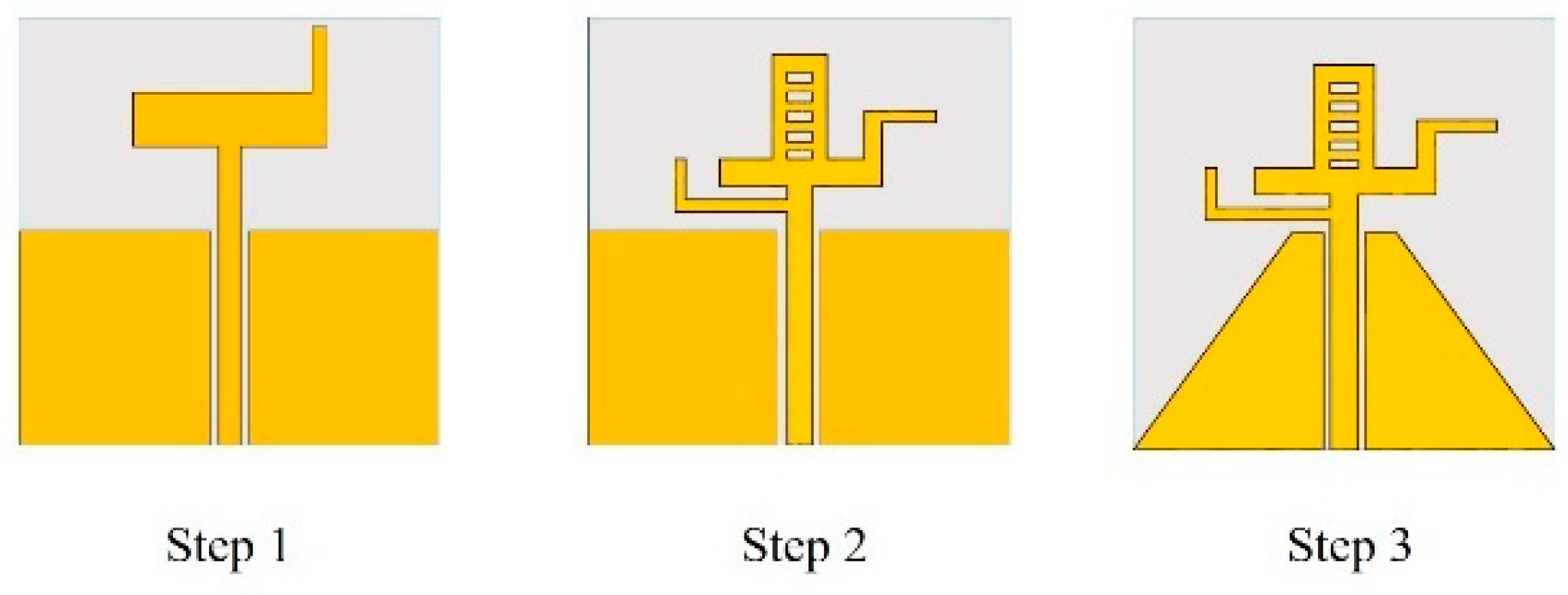
and a thickness of 1.6 mm. Firstly, the single-element antenna is optimized by making the changes into the simple monopole and in the CPW fed ground plane. The evaluation of single element UWB antenna is shown in
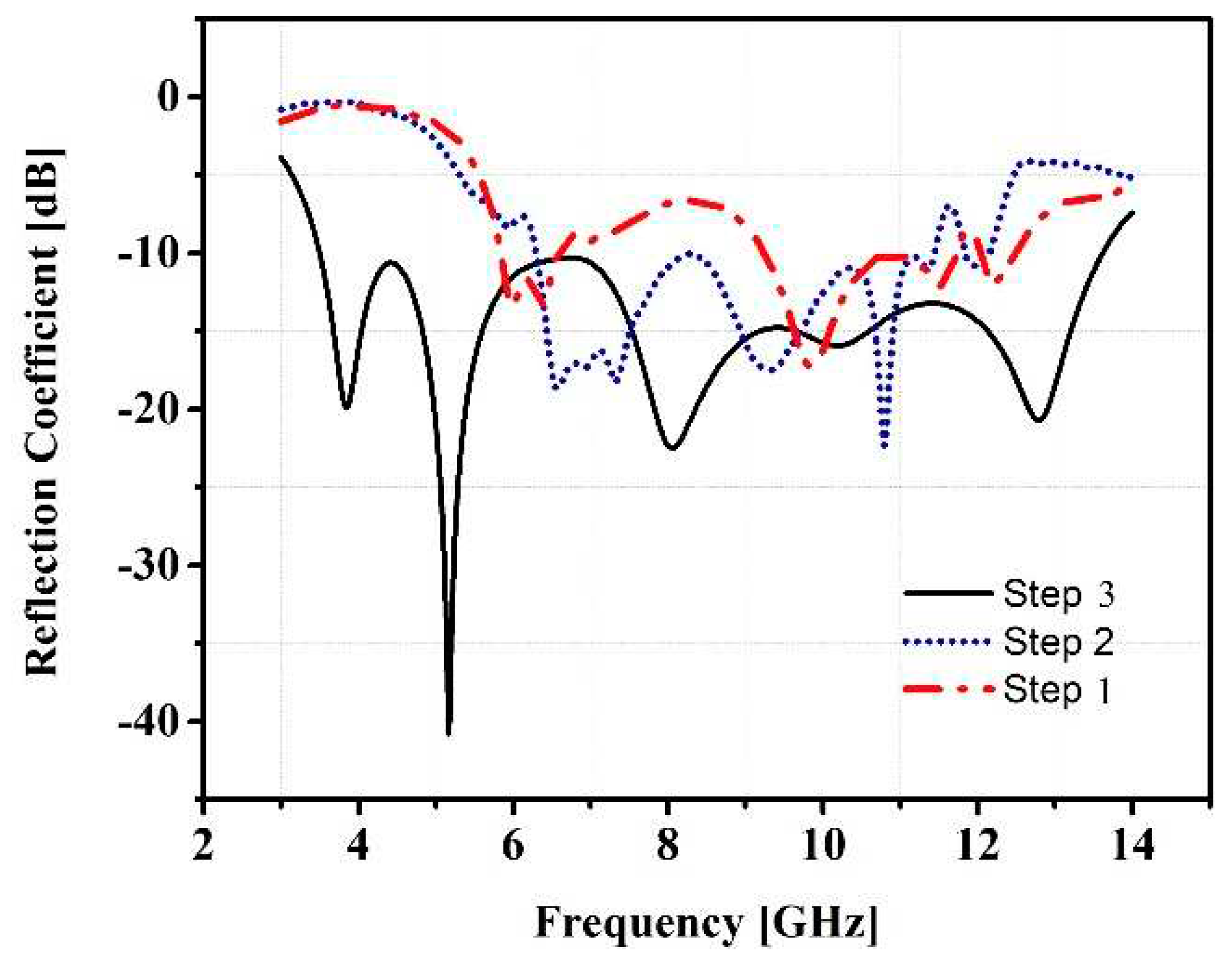
Figure 1. The design process starts from the simple monopole in step 1. Then a ladder structure is drawn in step 2, and this results in an increase in the bandwidth. After that chamfer was introduced in the ground in step 3 and the UWB range achieved covering the frequency range of 3.3 GHz to 13.5 GHz. The overall dimension of single element antenna proposed in this paper is 29 × 29 × 1.6 mm
3. The radiating element is copper with a thickness of 0.035 mm. The reflection co-efficient of the single element proposed antenna in three steps is shown in
Figure 2.
The labelled design of a proposed antenna is shown in
Figure 3, and
Table 1 shows below the physical dimensions of the proposed antenna.
2.2. Antenna Configuration
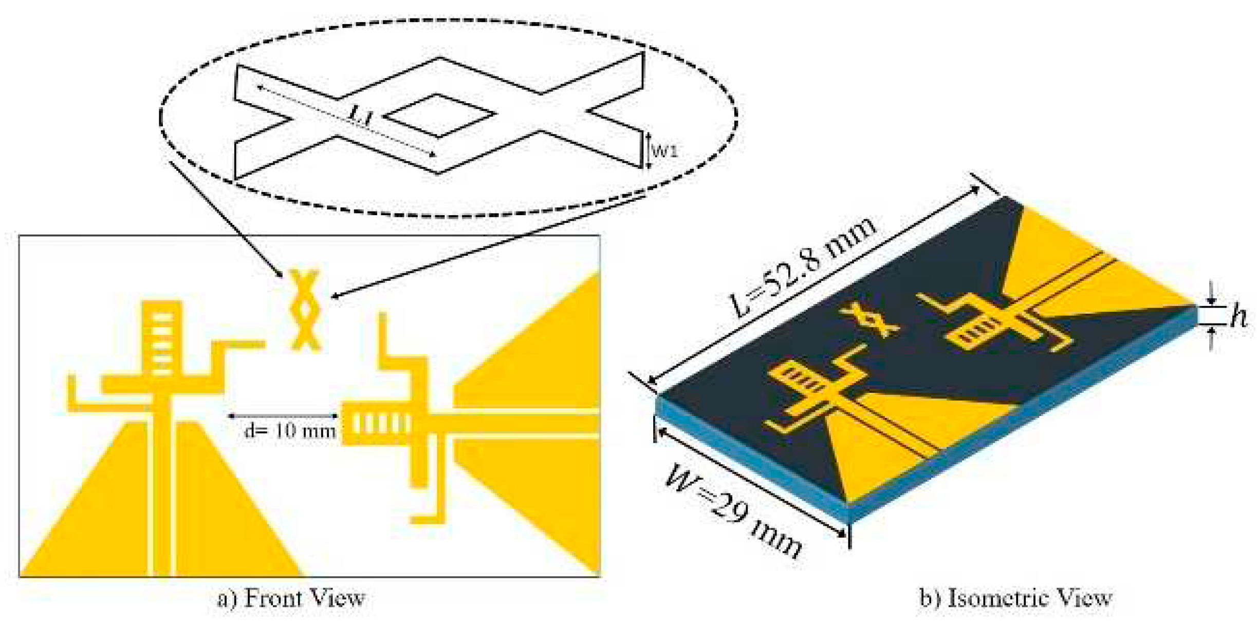
The two element UWB MIMO antenna described in this paper is simulated and optimized using the CST Microwave Studio. The MIMO structure of the proposed antenna consists of two same antenna elements placed orthogonally to each other’s as in [
3]. The distance between the antenna elements is specified as d = 10 mm. A parasitic element in the shape of two combined cross, is also incorporated in the design for achieving the minimum criteria of mutual coupling of less than -15 dB.
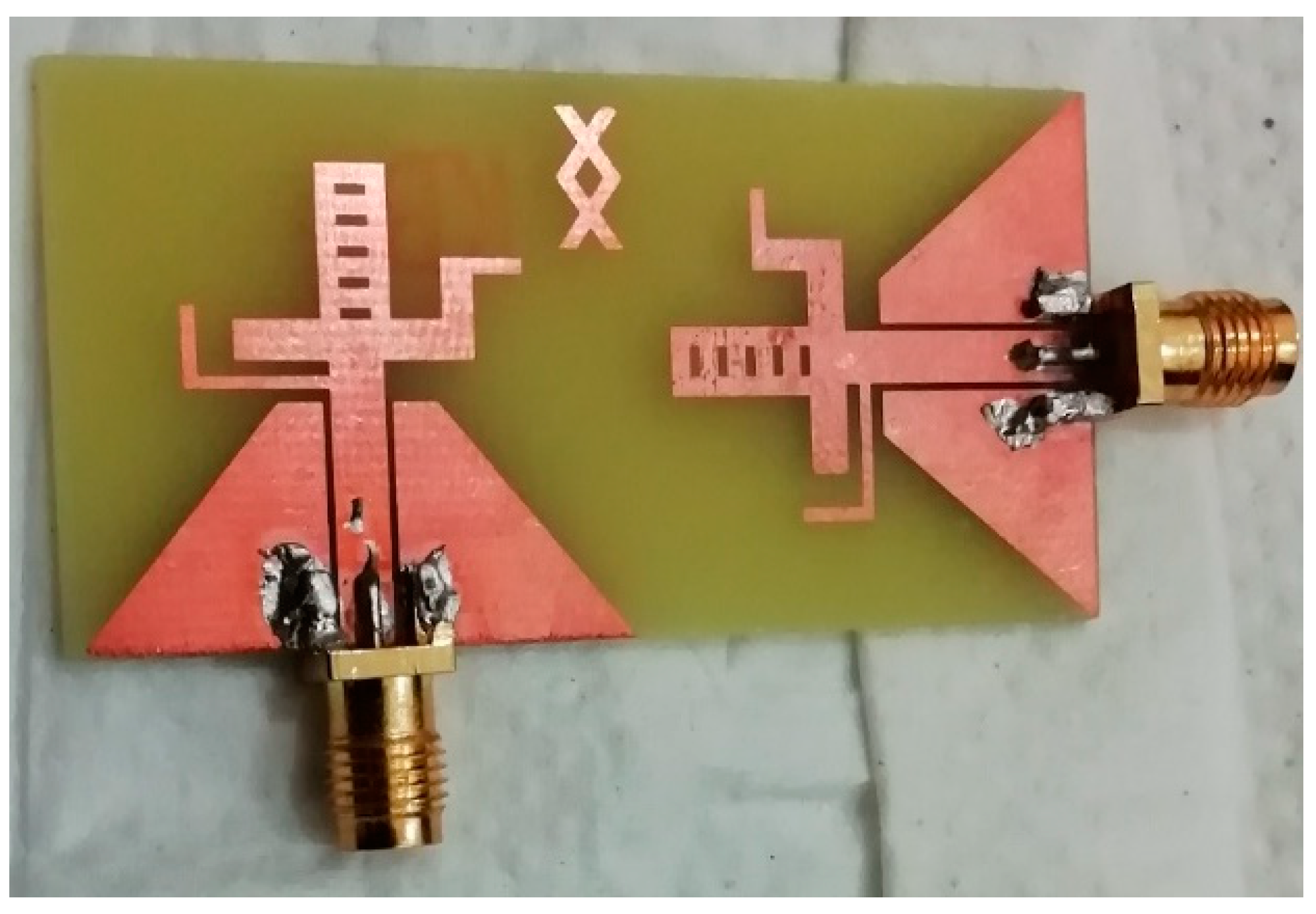
Figure 4 shows the front view and isometric view of the proposed MIMO antenna, and
Figure 5 shows the fabricated prototype.
3. Isolation Mechanism
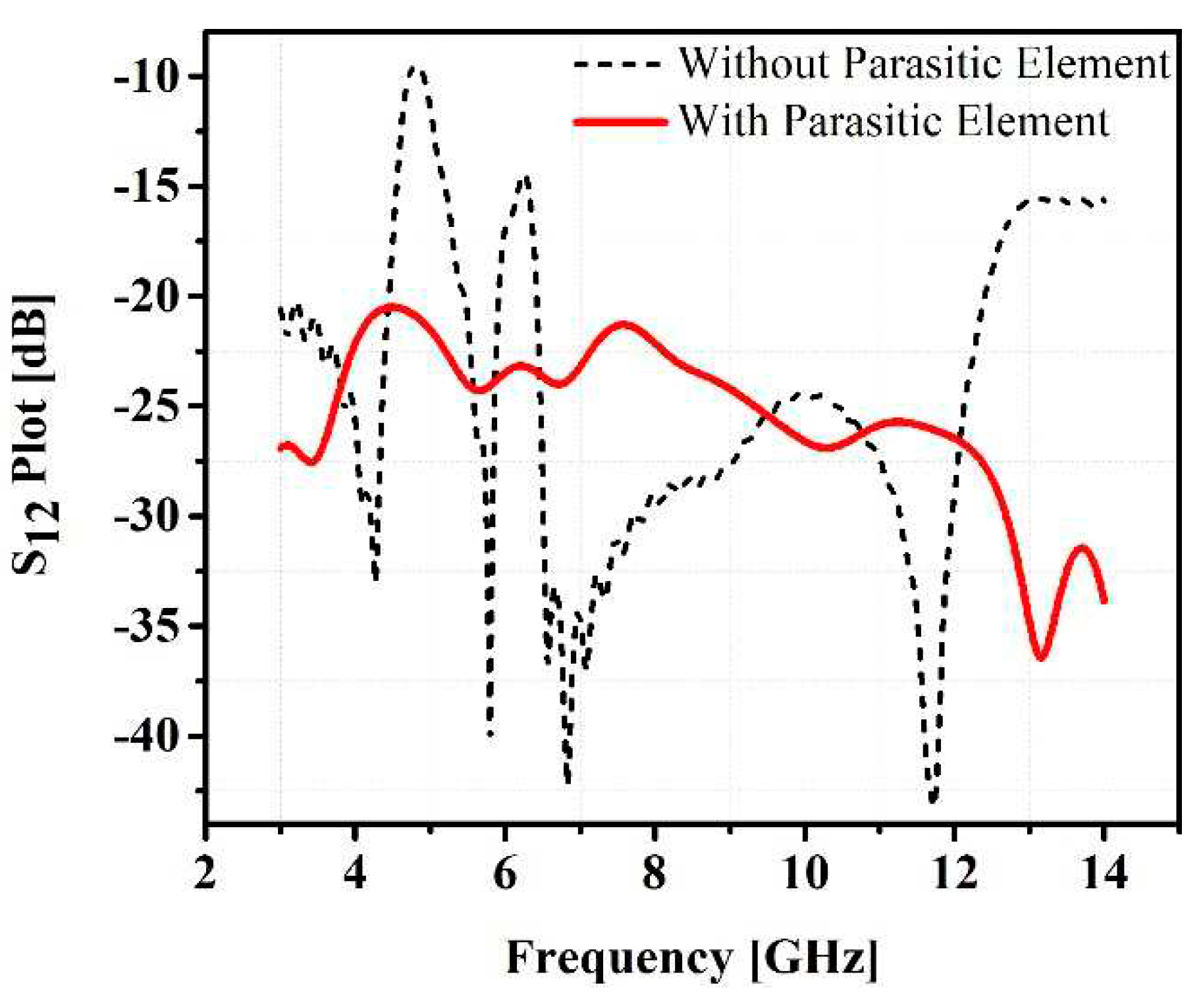
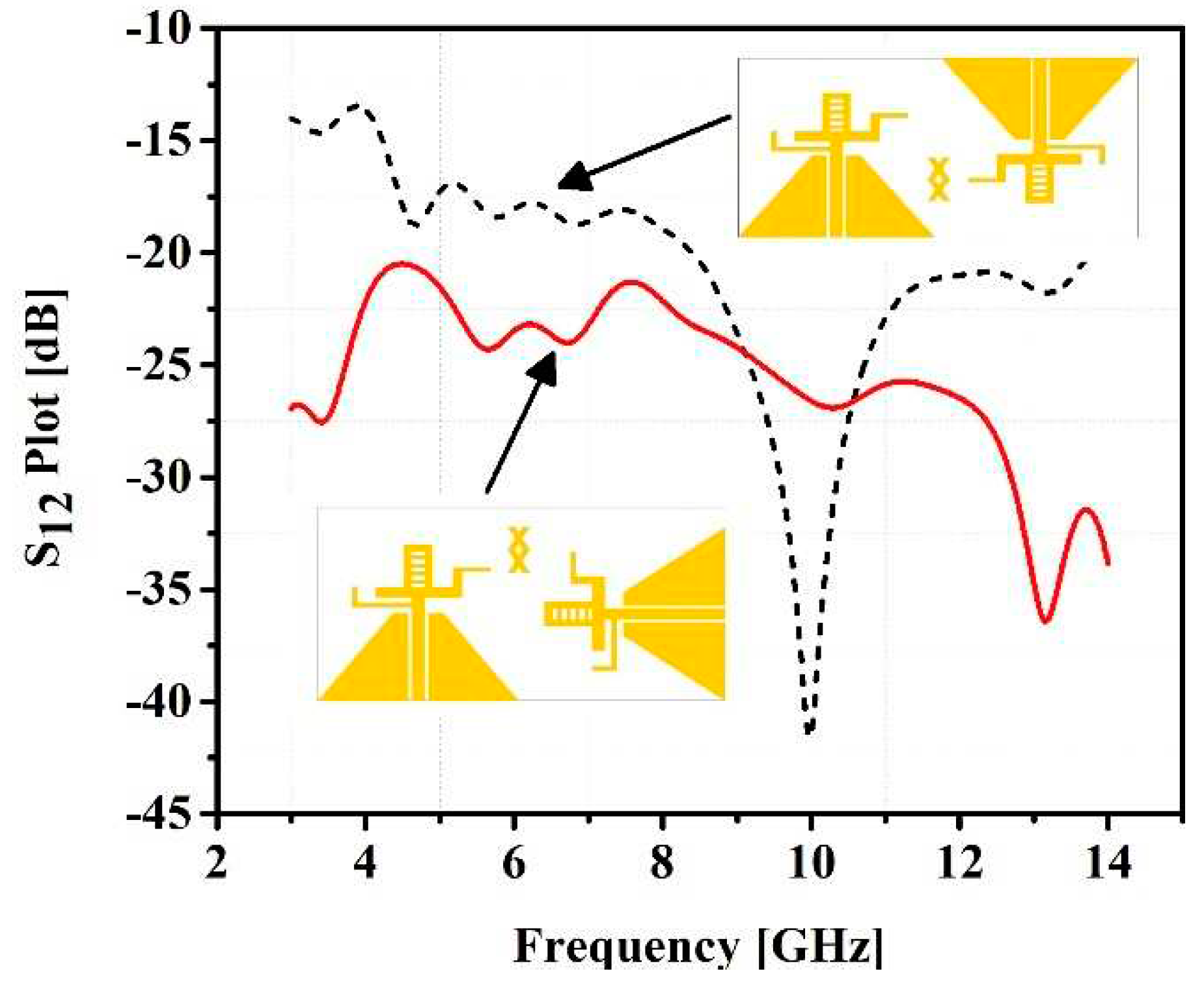
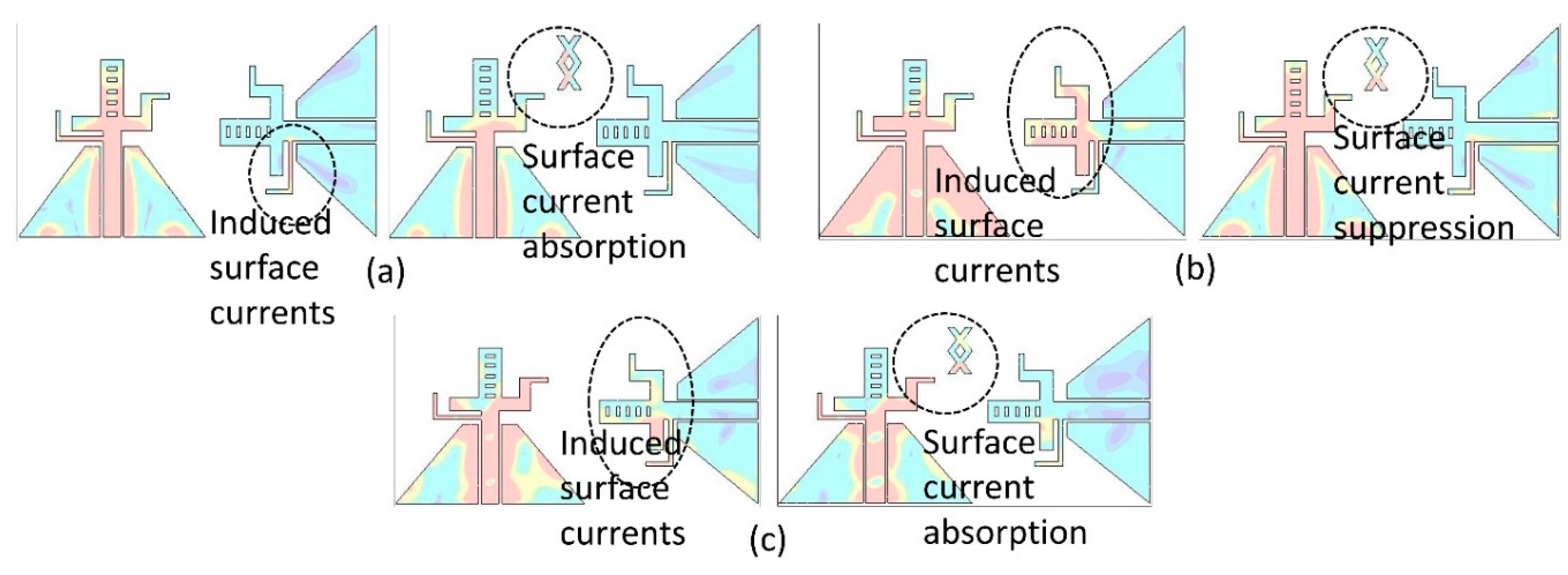
In this paper, two techniques are deployed to provide the isolation in between the two antenna elements to decrease the mutual coupling for proper functioning of MIMO antenna. A parasitic element in the form of two cross joined together, is placed in between the antenna elements. For further increase in the isolation, the two antennas are placed at an angle of 90 degree to each other.
Figure 6 shows the effect of placing the parasitic element in between the antenna elements.
Figure 7 shows the two cases of antenna elements orientation considering the isolation in between them.
4. Results and Discussion
4.1. Return Loss
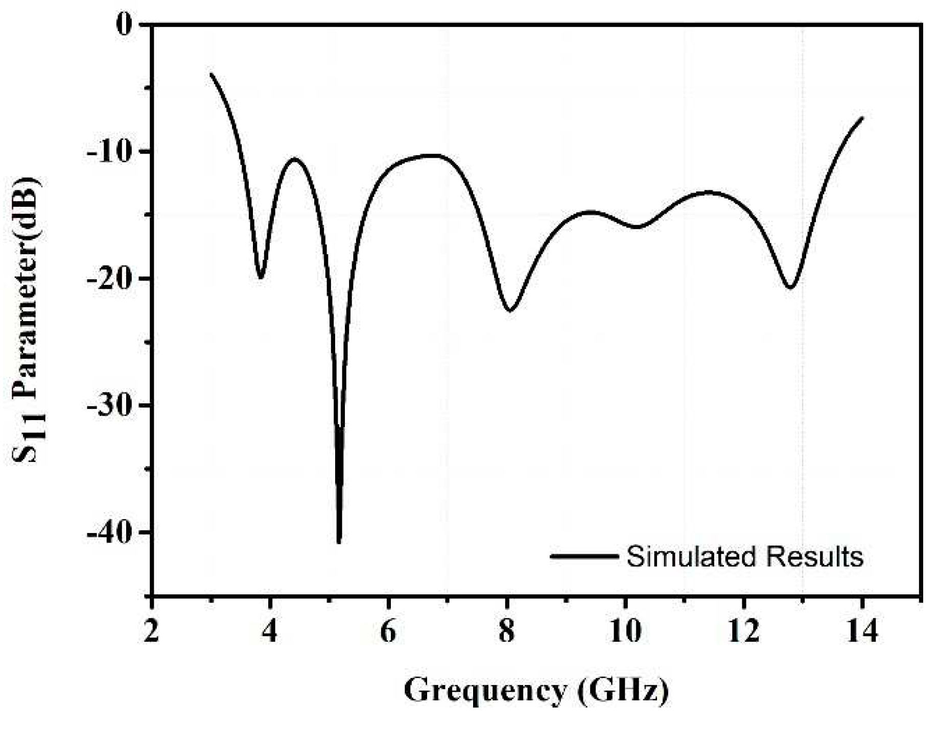
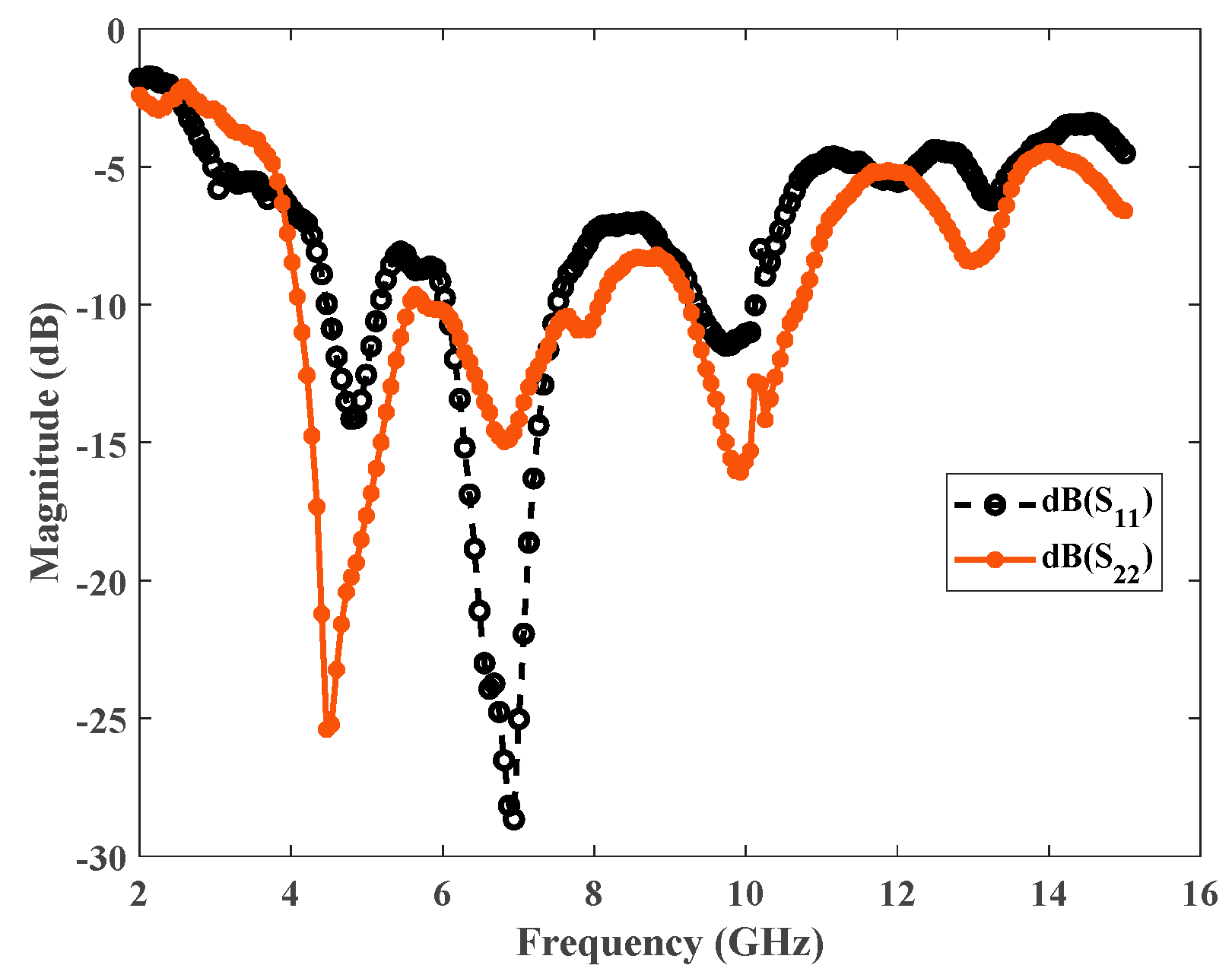
The proposed antenna is capable of operating from 3.3 GHz to 13.5 GHz. The
Figure 8 shows the S-parameter plot of the antenna at the above-described frequency range, and
Figure 9 depicts the measured results of a prototype. These results show that there is a defensible correlation between the simulated and experimental results.
4.2. VSWR
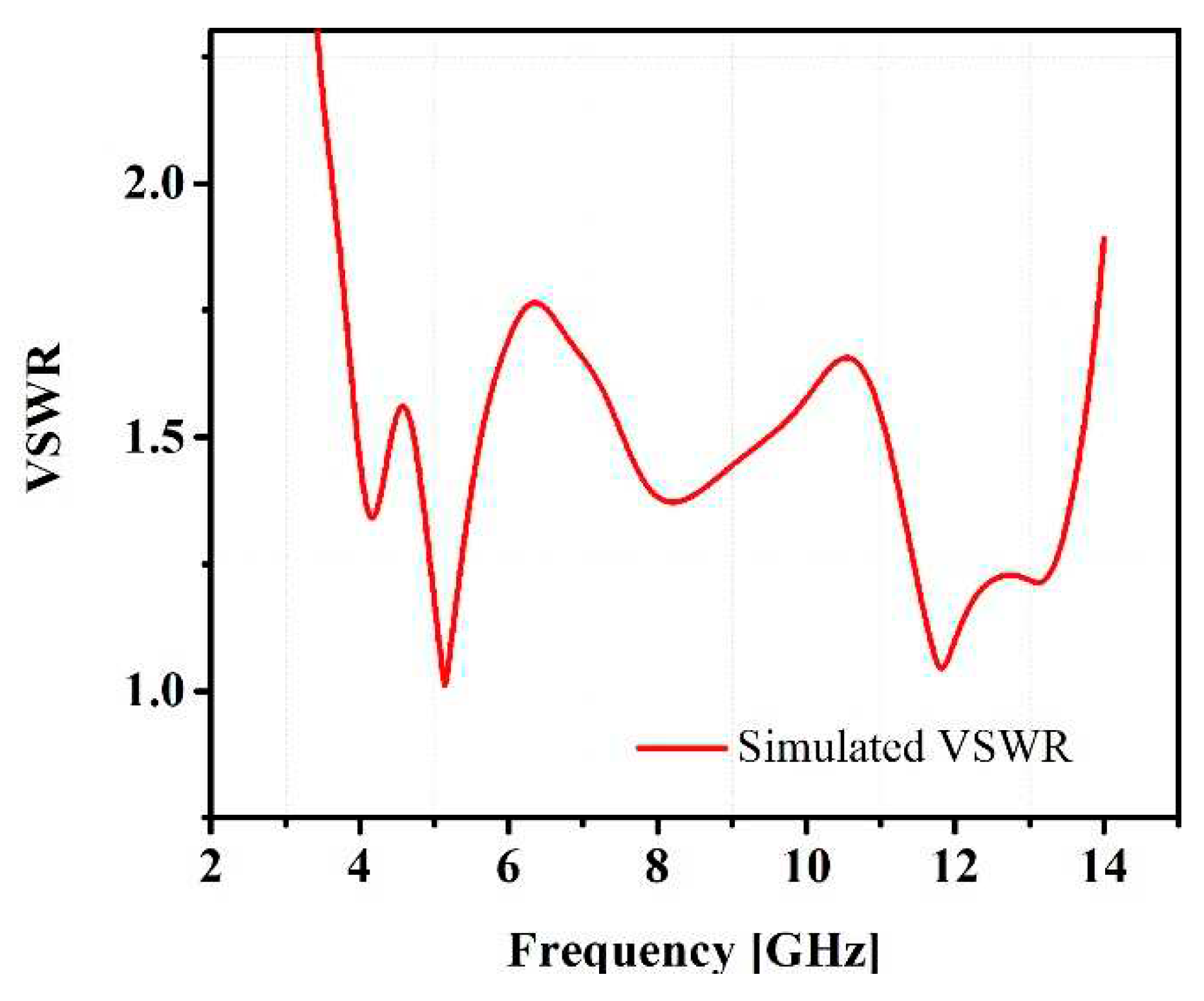
The simulated result of VSWR (voltage standing wave ratio) for the proposed antenna is shown in
Figure 10. The obtained values of VSWR at the desired bands are 1.10, 1.18, 1.30, and 1.12; they are all below 2, showing that the antenna exhibits good impedance matching.
4.3. Current Distribution
The current distribution at the resonance frequencies of the antenna is shown in
Figure 11.
Figure 11a shows that the current distribution is maximum across the feed line and at the middle of the radiator, which generates the frequency band of 3.38 GHz. It is apparent from
Figure 11b that the frequency of 5.56 GHz is achieved when the current intensity is maximum at the upper portion of the patch as well as along the feed line. In part (c), the maximum current density is observed at the feed line and the lower strips of both the left and right arms for the resonance frequency at 8.36 GHz.
4.4. Radiation Pattern
The normalized radiation patterns of E-plane and H-plane at the frequencies of 3.38, 5.56, and 8.36 GHz are shown in the
Figure 12. Moreover, the radiation patterns are showing the similarity to some extent which shows that there is effective radiation behavior in the described band. These far-field radiation plots are showing that the antenna described in this paper has approximate omnidirectional pattern which makes it useful for the desired applications.
4.5. MIMO Performance Parameters
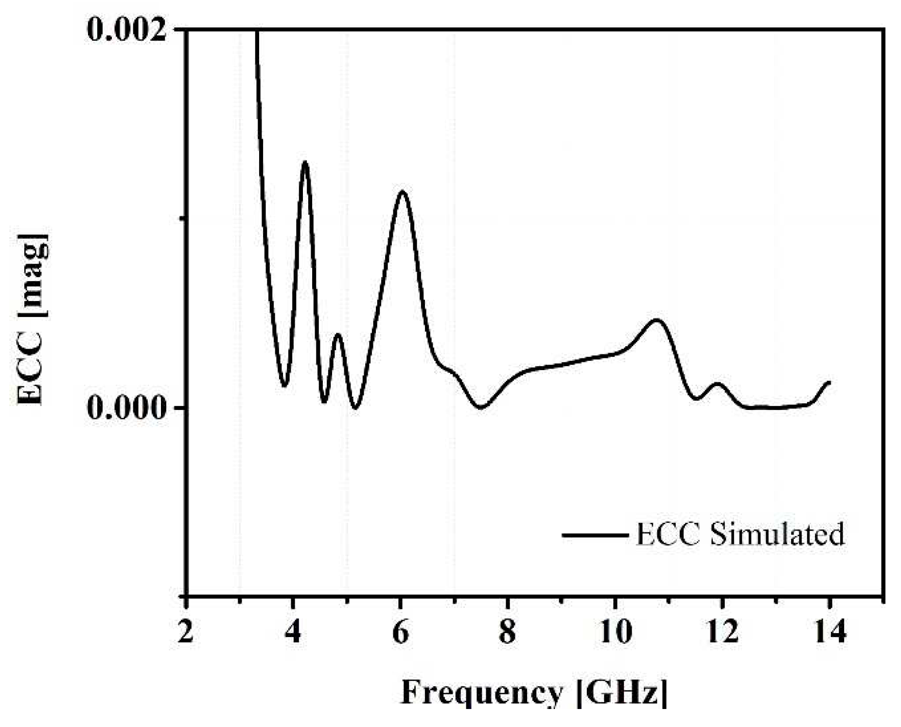
The values of Envelope Correlation Coefficient (ECC) can be found using the scattering parameters instead of far field parameters as it gives more accurate measurement of ECC without measuring the 3D radiation pattern. The relationship is assumed for rich scattering environment and given by following equation. Also, graphically shown in
Figure 13.
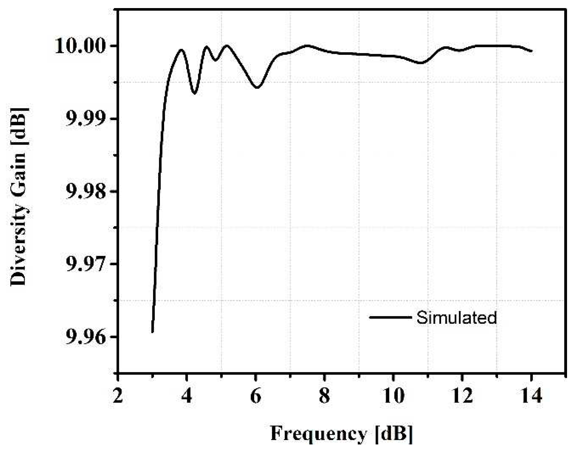
We can calculate the diversity gain with the help of ECC which is depicted in
Figure 14. The relationship in between the diversity gain and ECC is given as:
The above given relationship in between the correlation coefficient and diversity gain clearly shows that lower the correlation coefficient, higher the diversity gain. So, higher isolation is required in between the antenna elements otherwise the diversity gain will be low.
4.6. Gain and Efficiency
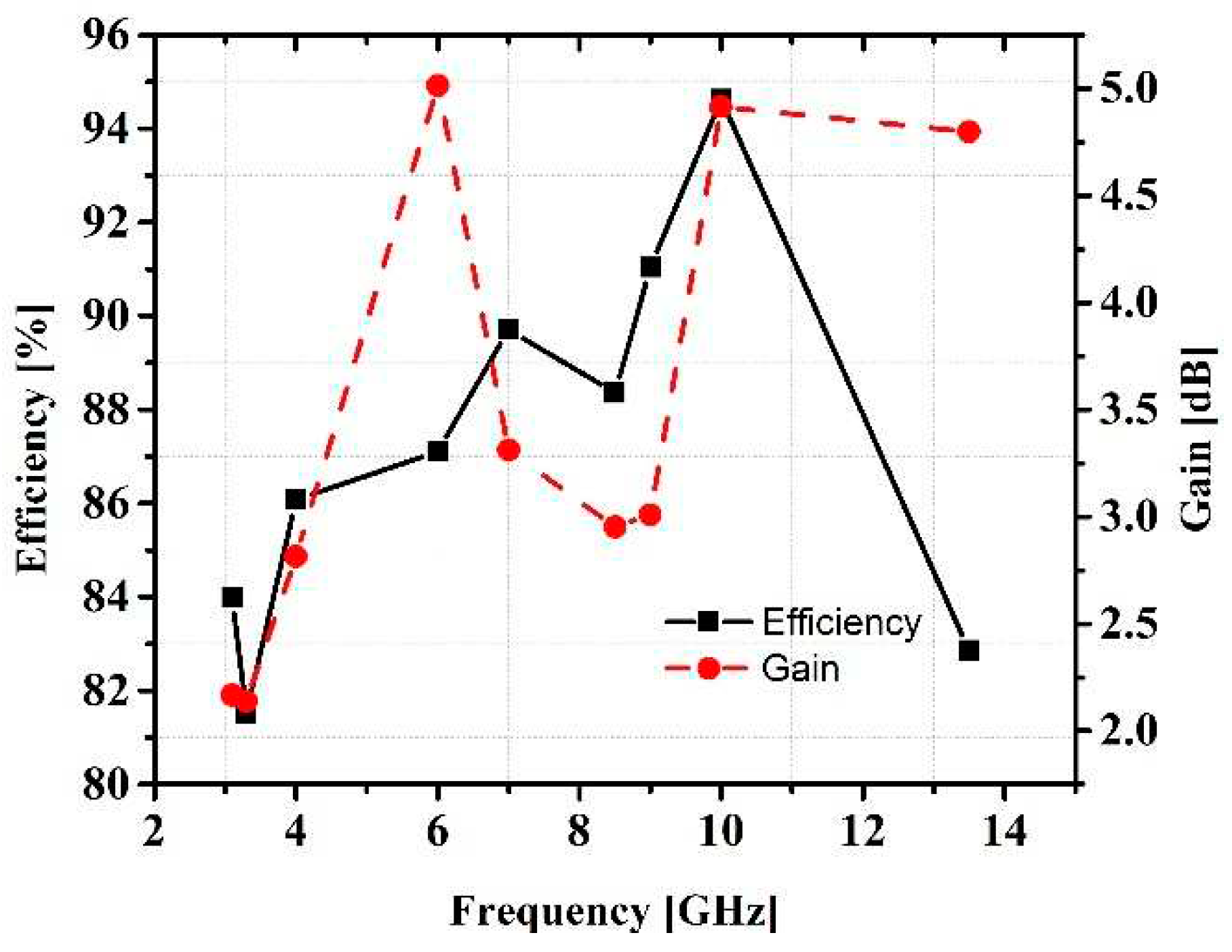
By using the far-field monitor in CST Microwave Studio, the gain and efficiency are calculated at the different frequencies. The gain of an antenna describes the transmitted power in the direction of an isotropic source. If gain of transmitting antenna is 3dB, it means that the power received by this antenna will be two times higher than the power received from the lossless isotropic antenna, providing the same input power in both cases. In this work, gain of the antenna varies from 2.02 to 3.06 dB throughout the frequency band. The gain of proposed antenna fulfills the requirements of some of the wireless communication standards.
The minimum observed value of efficiency is 82%. The efficiency is affected due to multiple bands of operation and high loss in FR-4 substrate (a loss tangent of δ = 0.025) which results in lowering the radiation efficiency. However, the radiation efficiency is in the range of (81-94) %, which shows that power received in far-field region is greater than the 50% of input power, making the antenna sufficient to work in the described applications. The antenna gain and the radiation efficiency are presented in
Figure 15.
Table 2 summarizes the overall performance of the antenna at the four distinct resonance frequencies. The presented work is compared with the recently published work in
Table 3.
5. Conclusions
There is an increasing need to do more with less to overcome the challenges of next-generation networks. The multiband feature of an antenna maximizes the available space at the user site by better management of antenna count. A quad-band CPW-fed microstrip patch antenna has been presented and fabricated for wireless and satellite applications. The experimental and simulated results show that the antenna presented in this paper can resonate at four different center frequencies 3.38, 5.56, and 8.36 GHz which cover WiMAX, WLAN, and C-band, respectively. The antenna has a compact size of 30.3 × 32.1 mm2 designed on commercially available substrate FR4, which makes it suitable for multiple low-cost applications along with being a good choice to be integrated with small devices.
Author Contributions
Conceptualization, Z.M. and A.E.; methodology, M.Z.; software, Z.M.; validation, N.B.; formal analysis, S.S.; investigation, M.Z.; resources, N.B.; writing—original draft preparation, Z.M.; writing—review and editing, M.Z.; visualization, S.S.; supervision, Y.A. All authors have read and agreed to the published version of the manuscript.
Funding
This research received no external funding.
Informed Consent Statement
Not applicable.
Data Availability Statement
Data can be shared upon request.
Conflicts of Interest
The authors declare no conflict of interest.
References
- M. A. Ul Haq, and S. Koziel, “Ground Plane Alterations for Design of High-Isolation Compact Wideband MIMO Antenna,” in IEEE Access, vol. 6, pp. 48978-48983, 2018.
- Malviya, L., Panigrahi, R., & Kartikeyan, M. (2017). MIMO antennas with diversity and mutual coupling reduction techniques: A review. International Journal of Microwave and Wireless Technologies.
- L. Liu, S. W. Cheung, and T. I. Yuk, “Compact MIMO Antenna for Portable Devices in UWB Applications,” in IEEE Transactions on Antennas and Propagation, vol. 61, no. 8, pp. 4257-4264, Aug. 2013. [CrossRef]
- K. Ding, C. Gao, D. Qu and Q. Yin, “Compact Broadband MIMO Antenna with Parasitic Strip,” in IEEE Antennas and Wireless Propagation Letters, vol. 16, pp. 2349-2353, 2017. [CrossRef]
- Jiang, T., Jiao, T., & Li, Y. (2018). A Low Mutual Coupling MIMO Antenna Using Periodic Multi-Layered Electromagnetic Band Gap Structures.
- S. Zhang and G. F. Pedersen, “Mutual Coupling Reduction for UWB MIMO Antennas with a Wideband Neutralization Line,” in IEEE Antennas and Wireless Propagation Letters, vol. 15, pp. 166-169, 2016. [CrossRef]
- M. A. Ul Haq and S. Koziel, “Ground Plane Alterations for Design of High-Isolation Compact Wideband MIMO Antenna,” in IEEE Access, vol. 6, pp. 48978-48983, 2018. [CrossRef]
- Yu Yin, Jingsong Hong, Chaoming Luo, Muhammad AMIN, A Compact Planar UWB MIMO Antenna using modified ground stub structure, IEICE Electronics Express, Article ID 14.20170883.
- Hassan, T., Khan, M.U., & Sharawi, M.S. (2018). FSS based Radiation Pattern Decorrelator for MIMO Antenna. 2018 IEEE International Symposium on Antennas and Propagation & USNC/URSI National Radio Science Meeting, 355-356.
- Z. Qamar, L. Riaz, M. Chongcheawchamnan, S. A. Khan and M. F. Shafique, “Slot combined complementary split ring resonators for mutual coupling suppression in microstrip phased arrays,” in IET Microwaves, Antennas & Propagation, vol. 8, no. 15, pp. 1261-1267, 9 12 2014.
- J. Ghosh, S. Ghosal, D. Mitra, and S. R. Bhadra Chaudhuri, “Mutual Coupling Reduction Between Closely Placed Microstrip Patch Antenna Using Meander Line Resonator,” Progress In Electromagnetics Research Letters, Vol. 59, 115-122, 2016.
- J. Choi, W. Hwang, C. You, B. Jung, and W. Hong, “Four-Element Reconfigurable Coupled Loop MIMO Antenna Featuring LTE Full-Band Operation for Metallic-Rimmed Smartphone,” in IEEE Transactions on Antennas and Propagation, vol. 67, no. 1, pp. 99-107, Jan. 2019.
- L. Kang, H. Li, X. Wang, and X. Shi, “Compact Offset Microstrip-Fed MIMO Antenna for Band-Notched UWB Applications,” in IEEE Antennas and Wireless Propagation Letters, vol. 14, pp. 1754-1757, 2015. [CrossRef]
- H. Hu, F. Chen, and Q. Chu, “A Wideband U-Shaped Slot Antenna and Its Application in MIMO Terminals,” in IEEE Antennas and Wireless Propagation Letters, vol. 15, pp. 508-511, 2016. [CrossRef]
- R. Anitha, P. V. Vinesh, K. C. Prakash, P. Mohanan and K. Vasudevan, “A Compact Quad Element Slotted Ground Wideband Antenna for MIMO Applications,” in IEEE Transactions on Antennas and Propagation, vol. 64, no. 10, pp. 4550-4553, Oct. 2016.
- Wenjing Wu, Bo Yuan, and Aiting Wu, “A Quad-Element UWB-MIMO Antenna with Band-Notch and Reduced Mutual Coupling Based on EBG Structures,” International Journal of Antennas and Propagation, vol. 2018, Article ID 8490740, 10 pages, 2018.
- D. Yadav, M. P. Abegaonkar, S. K. Koul, V. N. Tiwari, and D. Bhatnagar, “Two Element Band-Notched UWB MIMO Antenna with High and Uniform Isolation,” Progress In Electromagnetics Research M, Vol. 63, 119-129, 2018.
- Mathur, R. & Dwari, S. (2018). Compact 4-Port MIMO/Diversity Antenna with Low Correlation for UWB Application. Frequenz, 72(9-10), pp. 429-435. Retrieved 19 Jul. 2019.
- Wenjing Wu, Bo Yuan, and Aiting Wu, “A Quad-Element UWBMIMO Antenna with Band-Notch and Reduced Mutual Coupling Based on EBG Structures,” International Journal of Antennas and Propagation, vol. 2018, Article ID 8490740, 10 pages, 2018. [CrossRef]
- Anitha, R., Vinesh, P.V., Prakash, K.C., Mohanan, P., & Vasudevan, K. (2016). A Compact Quad Element Slotted Ground Wideband Antenna for MIMO Applications. IEEE Transactions on Antennas and Propagation, 64, 4550-4553.
- A. A. Ibrahim, J. Machac, R. M. Shubair and M. Svanda, “Compact UWB MIMO antenna with asymmetric
coplanar strip feeding configuration,” 2017 IEEE 28th Annual International Symposium on Personal,
Indoor, and Mobile Radio Communications (PIMRC), Montreal, QC, 2017, pp. 1-4. [CrossRef]
- H. Hu, F. Chen, and Q. Chu, “A Wideband U-Shaped Slot Antenna and Its Application in MIMO Terminals,” in IEEE Antennas and Wireless Propagation Letters, vol. 15, pp. 508-511, 2016. [CrossRef]
- L. Kang, H. Li, X. Wang, and X. Shi, “Compact Offset Microstrip-Fed MIMO Antenna for Band-Notched UWB Applications,” in IEEE Antennas and Wireless Propagation Letters, vol. 14, pp. 1754-1757, 2015. [CrossRef]
- J. Choi, W. Hwang, C. You, B. Jung, and W. Hong, “Four-Element Reconfigurable Coupled Loop MIMO Antenna Featuring LTE Full-Band Operation for Metallic-Rimmed Smartphone,” in IEEE Transactions on Antennas and Propagation, vol. 67, no. 1, pp. 99-107, Jan. 2019. [CrossRef]
- R. Hussain, M. S. Sharawi and A. Shamim, “An Integrated Four-Element Slot-Based MIMO and a UWB Sensing Antenna System for CR Platforms,” in IEEE Transactions on Antennas and Propagation, vol.66, no. 2, pp. 978-983, Feb. 2018. [CrossRef]
- S. W. Zehra, M. Zahid and Y. Amin, "A Compact 2 Element MIMO Antenna for UWB Applications," 2021 IEEE Asia Pacific Conference on Wireless and Mobile (APWiMob), 2021, pp. 247-252, doi: 10.1109/APWiMob51111.2021.9435237.Author 1, A.; Author 2, B. Book Title, 3rd ed.; Publisher: Publisher Location, Country, 2008; pp. 154–196.
|
Disclaimer/Publisher’s Note: The statements, opinions and data contained in all publications are solely those of the individual author(s) and contributor(s) and not of MDPI and/or the editor(s). MDPI and/or the editor(s) disclaim responsibility for any injury to people or property resulting from any ideas, methods, instructions or products referred to in the content. |
© 2023 by the authors. Licensee MDPI, Basel, Switzerland. This article is an open access article distributed under the terms and conditions of the Creative Commons Attribution (CC BY) license (http://creativecommons.org/licenses/by/4.0/).
