1. Introduction
The corrosion resistance of titanium and its alloys is remarkable, thanks to the instantaneous formation of an oxide film on the surface of the titanium. This allows it to perform excellently in a variety of environments, including seawater, organic compounds, acids, bases, among others.
One of the most predominant applications of biomaterials is orthopedic implants, because it is increasingly common structural involvement of joints such as knees, femur, shoulder, and hip among others, in addition to the affectations by accidents, making possible through the use of biomaterials as structural components, the recovery in terms of mobility of patients. The most used metallic materials today for the manufacture of implants are stainless steels, cobalt-chromium alloys, and pure titanium or alloyed with other metals, however, this reduced number of metals does not always meet the requirements as a biomaterial since in some cases they produce failures such as wear, corrosion, the release of chemical species among others, so techniques are applied to improve their behavior in this regard, among others, through surface treatments [
1].
Information in the literature on titanium and vanadium nitride has demonstrated the superior performance of such coated ternary compounds compared to those of pure TiN and VN, with respect to their hardness and behavior in tribological environments [
2]. Modification of the coating composition by altering the process parameters allows to determine that Ti-V-N thin films sprayed with magnetron have high hardness, excellent thermal stability, and better wear resistance [
3].
The corrosion resistance of implant materials has been studied using different techniques, including electrochemical impedance spectroscopy (EIS) has been used [
4,
5]. Several researchers have studied PVD coatings in the field of biomedical applications since this type of technique offers high purity, high density in coatings, excellent resistance to adhesion with the substrate and smooth surfaces with roughness in the nanometer range [
6,
7]. The PVD process, in addition to improving mechanical and electrochemical properties, offers advantages such as durability, costs and effectiveness compared to an uncoated part; It is also important to take into account the price of the complete equipment, performance and reliability, operating costs, the useful life of the equipment among others such as dimensions of the part to be coated and the environmental impact compared to other techniques. This is interesting for the development of low-cost materials with similar or better responses in the human body [
8].
The ability of titanium to promote bone growth is enhanced by TiVN coatings given the appropriate tissue response, allowing these coatings to be used in permanent implants, resulting in proper bone growth (osseointegration) and no production of toxic particles. Furthermore, with the trilayer, it is possible to increase the surface roughness, as well as the increase in pore size in such a way that it allows bone development and, consequently, rapid patient recovery. Additionally, this surface modification improves wear resistance [
9]. Moreover, it's noticed how Vanadium notably impacts the mechanical and tribological features of the coatings, particularly as the Vanadium (V) concentration rises, resulting in improved resistance to penetration. Alloys with a higher atomic percentage (%at) of V demonstrate superior tribocorrosive behavior compared to those with a higher %at of Titanium. This showcases a beneficial inter-play between corrosion and wear, maximizing the applicability of these coatings in the biomedical sector. As outlined by M. Azzi and the team, the existence of the TiN layer on the Ti surface raised the open circuit potential. Hence, the present study is dedicated to the electrochemical analysis of the TiVN trilayer in a simulated physiological medium fluid, evaluating its performance both before and during wear.
2. Materials and Methods
2.1. Deposition
The TiVN trilayers are applied onto 12 mm diameter and 3 mm thick titanium discs that have been meticulously prepared to achieve a smooth, mirror-like surface. Prior to coating, the samples undergo a thorough cleaning process using ethanol in a multi-stage ultrasonic bath. These trilayers are deposited through magnetron sputtering within a carefully controlled gas environment comprising argon and nitrogen. The operational parameters mirror those detailed in the method by Ríos and colleagues [
10]. The films are created by modulating the sputtering power for each element (Titanium - Ti, and Vanadium - V), resulting in eight distinct surface layer conditions. In condition A, the sputtering energy of V is held steady, while in condition B, the sputtering energy of Ti remains constant.
Figure 1 illustrates the fundamental configuration of these trilayers.
2.2. Electrochemical and wear tests
To evaluate wear simultaneously with electrochemical tests, a Microtest equipment arranged in linear configuration is used to which a cell of three electrodes is coupled it works with a load of 10 N, a distance of 100 m, using as pin a polyetheretherketone sphere (PEEK), plasma is used as an electrolyte acting as a medium to simulate the conditions of the human body; A silver/silver chloride electrode (Ag/AgCl), a platinum bar as a counter electrode and the exposed surface of TiVN (1 cm
2) as a working electrode are used. The composition of the electrodes is given in
Table 2. A total volume of 150 ml of simulated physiological medium fluid (electrolyte) and a scanning rate of 1 mV/s were used. Tests are performed at 0, 24, 192 and 384 hours, in dry and plasma. For EIS the frequencies used between 100 kHz and 10 mHz and an AC voltage of 10 mV (rms). Nyquist and Bode diagrams are obtained to obtain information about the resistance, capacitance and charge transfer processes that occur in the electrochemical system and the respective equivalent circuit.
3. Results and discussion
3.1. EDS Energy Dispersive Spectroscopy
Taking into account the established procedure for the application of the coating, an analysis was carried out on films with various deposit configurations in order to verify the formation of the trilayer. The EDS peaks in
Figure 2 show that it is a coating composed of different proportions of titanium (Ti), vanadium (V), and nitrogen (N), in accordance with the constituent components of the targets used and the reactive gas injected during the discharge process, the figure shows the resulting spectrum and the point on which EDS was made. In this sense, a high percentage of nitrogen stands out, while the amounts of titanium and vanadium are lower according to the information presented in
Table 2.
Following the objectives of the research and the capabilities of the equipment used for the deposition of the coating, the de-posit conditions were kept constant, which ensured the chemical composition of the coating. The EDS results for each coating system, presented in
Table 2, indicate that the proportion of titanium tends to increase with the increase in the power of cathodic sputtering of this element. Similarly, an increase in the content of vanadium is recorded as the power of vanadium sputtering increases, which is consistent with the findings previously reported by T. Deeleard et al. (2011). In addition, the effect of the atomic ratio between vanadium and titanium at the atomic level is evidenced [
11].
3.2. Scanning Electron Microscopy (SEM)
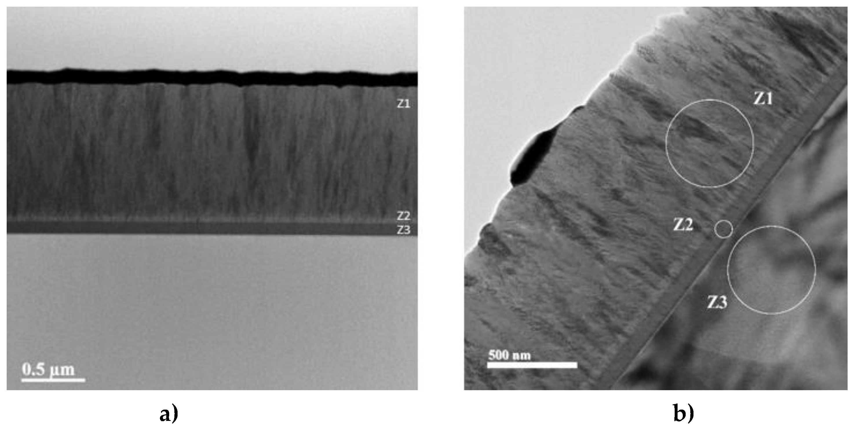
An analysis of the cross-section of the Ti samples coated with TiVN reveals the presence of the three deposited layers which can be observed in
Figure 3, Figure (a) shows the formation of the trilayer, figure (b) Z1 corresponds to the surface layer of the coating (TiVN), Z2 to the metal layer (Ti or V), Z3 to the substrate.
3.2 AFM measurements: As shown in
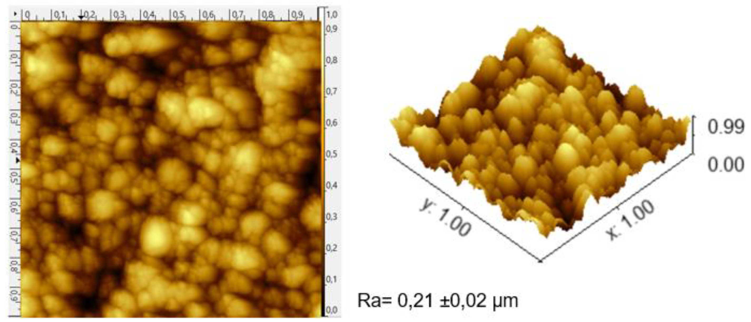
Figure 4, taking the TiVN
B4 system as an illustration, the growth process exhibits a granular pattern, showcasing layer roughness and grain size. Generally, the resulting coating systems display well-defined columns terminating in a dome-like fashion. Given that corrosion processes tend to increase the roughness of titanium, it is deemed a significant aspect of adhesion and colonization. Consequently, coatings with lower vanadium and titanium content, corresponding to smoother systems, are anticipated to have reduced biofilm accumulation on their surfaces. This would be beneficial, for example, in cases of dental implants to prevent peri-implantitis [
12,
13,
14].
The results of each analysis (
Figure 4), along with the data provided by the Gwyddion version 2.51® software, allowed for the calculation of the average roughness (Ra) values of all samples. In the case of the TiVN
A1 to TiVN
A4 samples, the Ra values averaged 165 nm, while the TiVN
B1 to TiVN
B4 samples exhibited an average roughness of 170 nm (TiVN
B4 Ra ≈214 ± 0.02 nm with the highest value). These data are fundamental for the calculations of the friction coefficient in the coatings and to determine how they influence the response of the system to sliding phenomena. The surface texture remains consistent across all samples (0.15 ± 0.03 nm) and is influenced by the masking effect caused by the base metal's roughness (1.3 μm). The consistent roughness values are appropriate due to their favorable influence on cellular metabolism. This characteristic demonstrates the applicability of the coatings as a component for implantation. It ensures that they do not hinder bone growth around the coating by preventing the formation of tissue, thus promoting favorable behavior.
3.3. Contact Angle
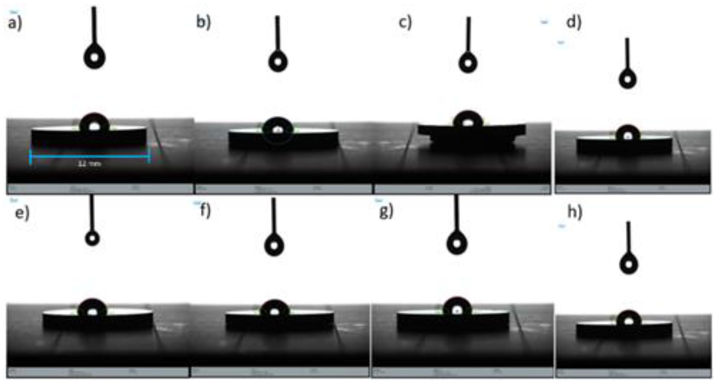
The contact angle (wettability) results indicate that the surfaces of the TiVN
A1, TVN
A2, TiVN
B2, and TiVN
B4 coating systems (see
Figure 5) exhibit significantly lower contact angles compared to the other systems. On the other hand, the TiVN
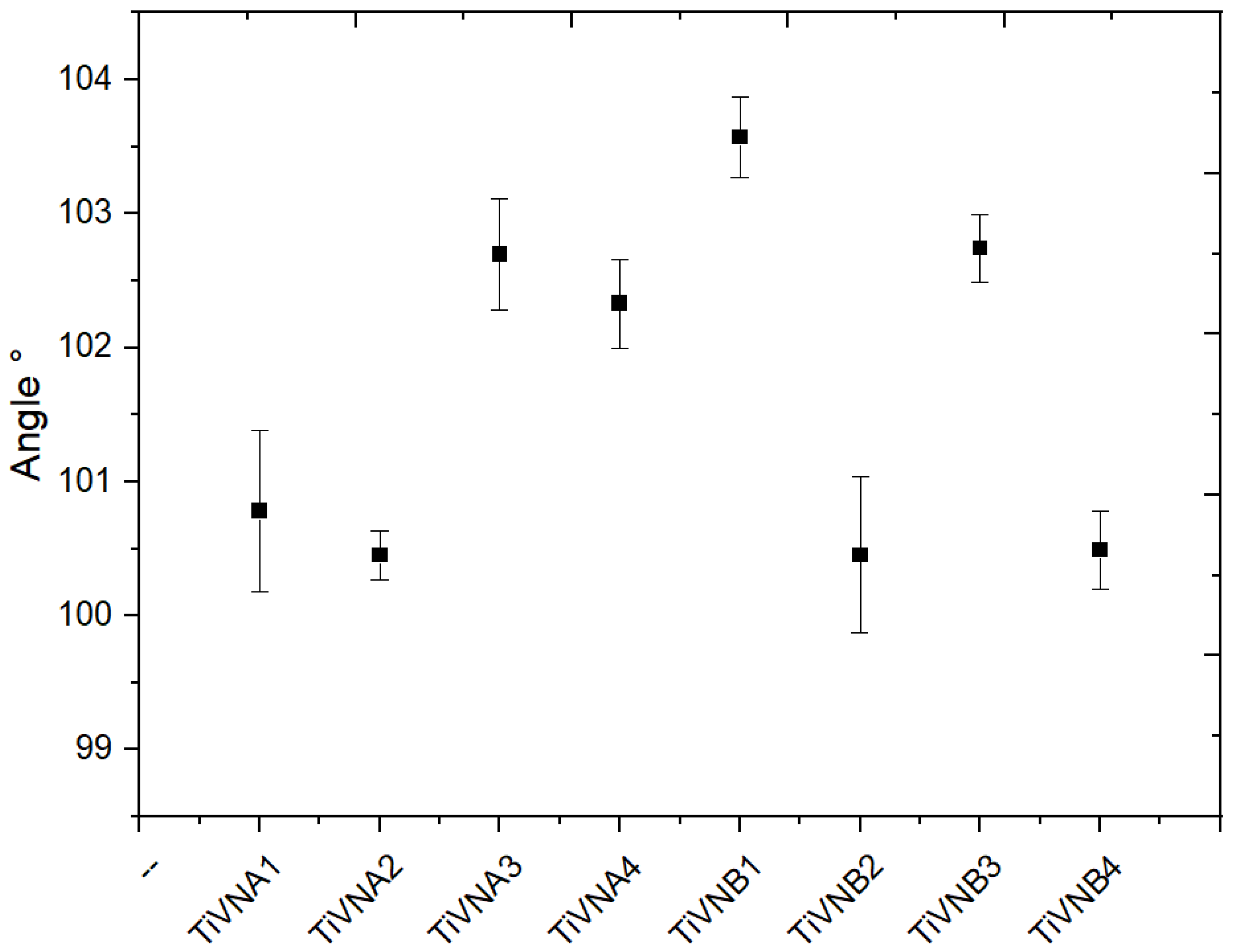
B1 sample, as represented in
Figure 6, shows a higher contact angle value, which is consistent with the roughness values in TiVN
B2 and TiVN
A3, where the standard deviation was higher, especially for TiVN
B2. For this system, the spray power was equal for both elements (Ti and V).
On average, the contact angle values are around 102.54°, in contrast to the un-coated Ti sample, which has a contact angle of 85.2 ± 1.5°. These results suggest significant differences in wettability between coating systems, which could influence their interaction with liquids and possibly their behavior in biomedical or implant applications.
Due to the higher surface tension of water compared to the tension at the liquid-solid interface, a distinct droplet is formed on the surface. TiVN films are categorized as Type I hydrophobic according to the standard, as hydrophobicity increases when θ > 90º, demonstrating the surface uniformity of these films. It’s clear that the contact angle diminishes as the contact surface becomes more polished.
3.4. EIS Electrochemical Impedance Spectroscopy
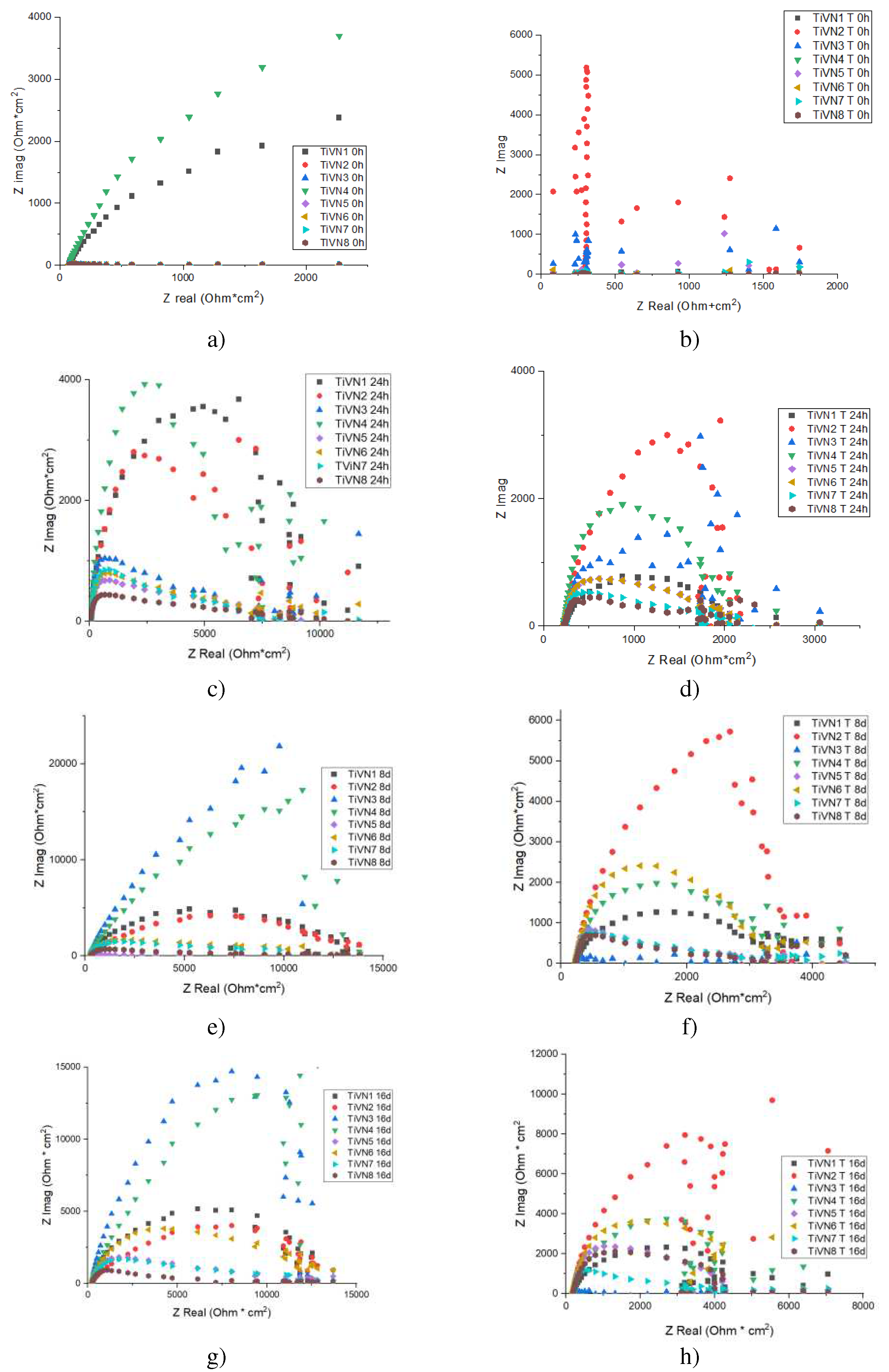
The EIS results for TiVN coating systems under dry conditions yield the Nyquist diagram. The diagrams for the TiVN samples are shown at zero, one, eight, and sixteen days of exposure. Prior to slip-page, it’s noted that the rise in vanadium and titanium concentration doesn’t significantly affect the system’s impedance. As the exposure time is prolonged, the resistance to charge transfer also increases. This is due to the formation of layers of vanadium oxide and titanium oxide, which become denser over time. Consequently, the contact between the surface of the substrate and the environment is reduced. This is due to the formation of vanadium oxide and titanium oxide layers, which become denser over time. Consequently, the contact between the substrate surface and the environment is reduced.
The study of Electrochemical Impedance (EIS) is depicted in the Nyquist diagram shown in
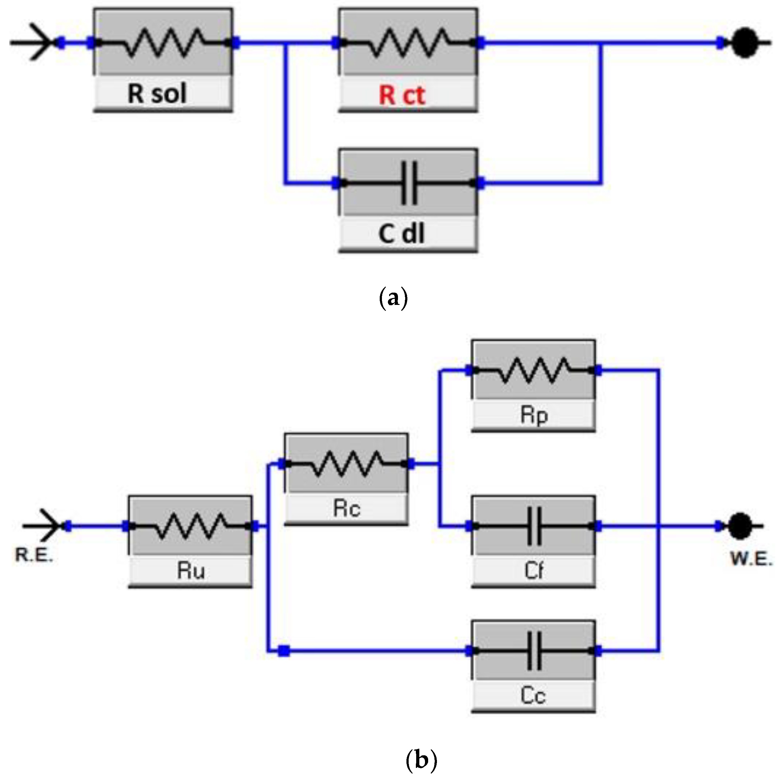
Figure 7, which presents a single semicircle. This pattern can be modeled using the Randles equivalent electrical circuit, as illustrated in
Figure 8(a). This circuit comprises several elements, including a solution resistor (Rs) that signifies the electrolyte’s resistance, a charge transfer resistor (Rct) that characterizes the resistance to charge transfer at the interface between the working electrode and the electrolyte, and a constant phase element (Cdl) symbolizing the double-layered capacitance on the surface of the electrode.
The findings indicate that the TiVN layer enhances corrosion resistance as the duration of exposure to the electrolyte (plasma) extends. Initially, the Rct was 10.50 Ohms at zero time. However, after 384 hours of exposure, the Rct significantly rose to 13.87 Ohms, signifying an enhancement in corrosion resistance. This implies that the TiVN layer is effective in shielding the substrate from corrosion when in contact with the solution that mimics body fluids.
Importantly, after subjecting the TiVN layer to slip wear tests, the Rct resistance decreased to 2.9 Ohms. This change suggests that the TiVN layer became less resistant to corrosion due to the normal wear process. Reactions in the solution simulating body fluids (plasma) affected charge flow control in the coating system. The electrical circuit representing the system reflects this decrease in corrosion resistance, as shown in
Figure 8(b), where double capacitance and double charge transfer resistance are introduced, describing the behavior during immersion and sliding.
3.5. Wear Analysis and Coefficient of Friction
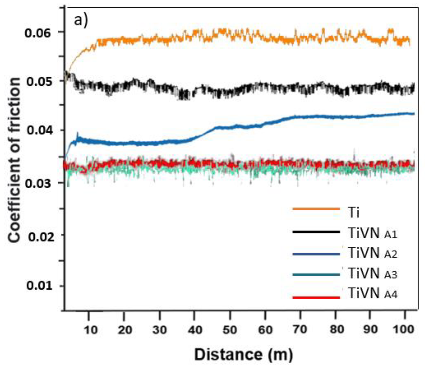
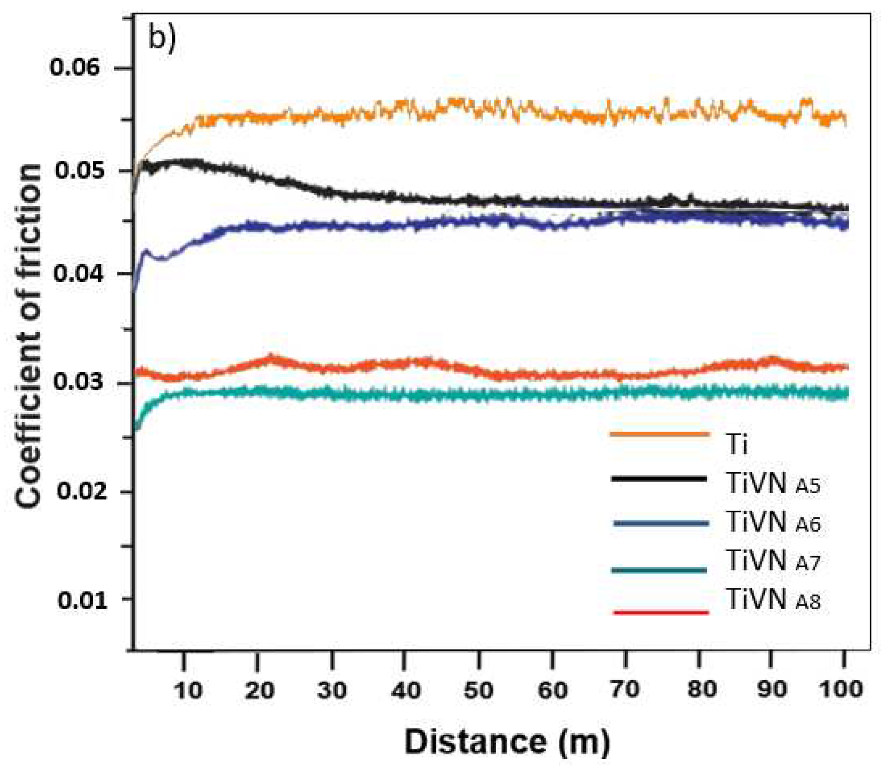
The friction coefficients of the coatings are derived from the wear test results. Two phases are observed: taxiing and steady state. In general, compared to the substrate, the trilayers exhibit lower friction coefficients, indicating a similar trend to the wear rate, as shown in
Figure 9. The TiVN
A4 and TiVN
B1 coatings displayed the highest friction coefficient, measuring at 0.045 ± 0.01 and 0.048 ± 0.02 respectively, while TIVN
B3 exhibited the lowest at 0.0286 ± 0.02. The impact of vanadium on sliding characteristics is evident, with a significant decrease when an adequate vanadium quantity was introduced while maintaining low titanium content. The adhesion of abrasive particles between the pin and the sample led to a gradual increase in the COF in certain instances until it reached a peak, stabilizing once the surface was clear of such particles (
Figure 9).
4. Conclusions
Integrated electrochemical testing serves as a crucial instrument for examining the interplay between corrosion and wear. These tests enable the assessment of the suggested materials in relation to corrosion, wear, and tribocorrosion. The results indicate that the TiVN layer enhances corrosion resistance as the duration of exposure to the electrolyte (plasma) extends. Notably, after 16 days of exposure, there was a significant rise in the Rct, indicating an improvement in corrosion resistance. This suggests that the TiVN layer is effective in safeguarding the substrate from corrosion when in contact with a solution that mimics body fluids.
The results suggest that the TiVN layer initially increases corrosion resistance, which could be beneficial in medical applications, such as implants. However, it’s crucial to consider the impact of wear on the longevity of this corrosion protection. Future research could focus on creating coatings that maintain their corrosion resistance even after experiencing slip wear.
Author Contributions
Conceptualización, A. R., W.A, E. V; Metodología, W. A. and A. R. escritura y preparación del documento, A. R., A. J. P., D. F. A.; O. D. and D. F. A.; writing—review and editing, E. V.; Todos los escritores han revisado y dado su aprobación a la versión final del documento que se ha publicado.
Acknowledgments
A la Universidad Pedagógica y Tecnológica de Colombia, al Dr. Alberto Monsalve y al personal del laboratorio de Biomateriales de la Universidad Santiago de Chile Project FONDEQUIP N°EQM150139, FONDEQUIP EQM 190002. A los miembros del Grupo interdiciplinario de Nanotecnologia (GINA), al labora-torio de Materiales Hibridos (HML), al DIMAT de la Universidad de Concepción. Al Ministerio de Ciencias, Tecnología e Innova-ción por el patrocinio para la realización de los análisis de labora-torio.
Conflicts of Interest
The authors declare no conflict of interest.
References
- Duffo G. Materials, raw materials, Biomater. (2011). http://www.bnm.me.gov.ar/giga1/documentos/EL007269.pdf.
- Roldan M.; Alcala M., Real C. Characterization of ternary TixV1-xNy nitride prepared by chemosynthesis. Ceram. (2012). Int. 687–693. [CrossRef]
- Knotek O.; Burgmer W. Stoessel C. Arc-evaporated Ti-V-N thin films. Surf. Coat. Technol. (1992). 54 – 55. 249-254. [CrossRef]
- Escudero M., González J. In vitro corrosion behavior of MA 956 superalloy. Biomater. (1994). 15. 1175. [CrossRef]
- Bundy K., Dillard J., Leudemann R. Use of a.c. impedance methods to study the corrosion behaviour of implant alloys. Biomater. 1993. (14) 529. [CrossRef]
- Ibrahim Z.; Sarhan A., Yusuf F., Hamdi M. Biomedical materials and techniques to improve the tribological, mechanical and biomedical properties of orthopedic implants—A review arti-cle. J. Alloys Compd. (2017). 636–667. [CrossRef]
- Sánchez-Bodón, J.; Diaz-Galbarriatu, M.; Pérez-Álvarez, L.; Moreno-Benítez, I.; Vilas-Vilela, J.L. Strategies to Enhance Bio-medical Device Performance and Safety: A Comprehensive Review. Coatings (2023), 13, 1981. [CrossRef]
- Orozco G.; Durán, P., & Aperador, W. Tribocorrosion Evalua-tion of Nb2O5, TiO2, and Nb2O5 + TiO2 Coatings for Medical Applications. Lubricants, (2021), 9(5), 49. [CrossRef]
- Tsai M., Chang Y., Huang H., Chi Chen Y., et al. Biological characteristics of human fetal skin fibroblasts and MG-63 hu-man osteosarcoma cells on tantalum-doped carbon films. Surf. Coat. Technol. (2014), 245 16-21. [CrossRef]
- Rios A.; Vera E., Aperador W., Ramirez J., Melendrez M. y col. Tribological characterization of TiVN trilayer coatings synthesized by sputtering for biomedical applications, Ceram. Int., (2023). [CrossRef]
- Pan J.; Thierry D., Leygraf C. Electrochemical impedance spectroscopy study of the passive oxide film on titanium for implant application. Electrochim. Acta., (1996). Volume 41. Issues 7–8. 1143-1153. ISSN 0013-4686. [CrossRef]
- Liu X., Yuan F., Wei Y. Grain size effect on the hardness of nanocrystal measured by the nanosize indenter. Applied Sur-face Science (2013), 279. 159–166. [CrossRef]
- Montero C. et al. Effect of codeposition parameters on the hardness and adhesion of TiVN coatings. Ceram. Int. 2015. [CrossRef]
- Hasegawa H., Kimura A., Suzuki T., Microhardness and structural analysis of (Ti,Al)N, (Ti,Cr)N, (Ti,Zr)N and films, J. Vac. Sci. Technol. A 18 (3) (2000) 1038–1040. [CrossRef]
Figure 1.
Basic configuration of the trilayer.
Figure 1.
Basic configuration of the trilayer.
Figure 2.
Example EDS Spectra of TiVN samples. The peaks of EDS show the elemental presence of titanium (Ti), vanadium (V), and nitrogen (N), in accordance with the targets and gas used. Source: Authors.
Figure 2.
Example EDS Spectra of TiVN samples. The peaks of EDS show the elemental presence of titanium (Ti), vanadium (V), and nitrogen (N), in accordance with the targets and gas used. Source: Authors.
Figure 3.
SEM micrographs of the transverse cut (TiVNA4) as a representation of a typical structure of thin ceramic coatings deposited by PVD (fine columnar).
Figure 3.
SEM micrographs of the transverse cut (TiVNA4) as a representation of a typical structure of thin ceramic coatings deposited by PVD (fine columnar).
Figure 4.
As a result of the AFM analysis, all samples show defined columns with dome-shaped terminations.
Figure 4.
As a result of the AFM analysis, all samples show defined columns with dome-shaped terminations.
Figure 5.
Contact angle tests. Contact angle measurement provides valuable insights into how biomaterials will interact with liquids. a) TiVNA1, b) TiVNA2, c) TiVNA3, d) TiVNA4, e) TiVNB1, f) TiVNB2, g) TiVNB3, h) TiVNB4.
Figure 5.
Contact angle tests. Contact angle measurement provides valuable insights into how biomaterials will interact with liquids. a) TiVNA1, b) TiVNA2, c) TiVNA3, d) TiVNA4, e) TiVNB1, f) TiVNB2, g) TiVNB3, h) TiVNB4.
Figure 6.
Contact angle variations for the TiVN systems were evaluated. The effect of the concentration of Ti and V is evident.
Figure 6.
Contact angle variations for the TiVN systems were evaluated. The effect of the concentration of Ti and V is evident.
Figure 7.
Nyquist TiVN diagram tests performed a) zero hours, b) 24 hours, c) 192 hours, d) 384 hours before wear a), c), e), g) and during wear b), d), f), h). Impedance increases with exposure time and with V concentration.
Figure 7.
Nyquist TiVN diagram tests performed a) zero hours, b) 24 hours, c) 192 hours, d) 384 hours before wear a), c), e), g) and during wear b), d), f), h). Impedance increases with exposure time and with V concentration.
Figure 8.
EIS analysis. Equivalent circuit of TiVN coatings a) Dry, b) In plasma. There is an effect between dry and plasma conditions, which benefit from the possible growth of a TiO2 layer.
Figure 8.
EIS analysis. Equivalent circuit of TiVN coatings a) Dry, b) In plasma. There is an effect between dry and plasma conditions, which benefit from the possible growth of a TiO2 layer.
Figure 9.
Friction coefficient of TiVN coatings using a 6 mm PEEK pin in plasma as an electrolyte with a normal load of 10 N a) Coating system Condition A, V Constant. b) Coating system Condition B, Ti Constant.
Figure 9.
Friction coefficient of TiVN coatings using a 6 mm PEEK pin in plasma as an electrolyte with a normal load of 10 N a) Coating system Condition A, V Constant. b) Coating system Condition B, Ti Constant.
Table 2.
EDS Results of TiVN samples. Atomic % for Ti, N and V.
Table 2.
EDS Results of TiVN samples. Atomic % for Ti, N and V.
| Coating |
N at. % |
V at. % |
Ti at. % |
TiVNA1
TiVNA2
TiVNA3
|
51,19 |
15,12 |
33,69 |
| 53,16 |
16,99 |
28,86 |
| 48,3 |
21,59 |
30,15 |
TiVNA4
TiVNB1
|
48,28 |
23,19 |
28,53 |
| 51,77 |
16,1 |
32,13 |
TiVNB2
TiVNB3
TiVNB4
Ti |
51,38 |
13,91 |
34,71 |
| 51,31 |
13,97 |
34,72 |
| 49,13 |
14,41 |
36,46 |
| |
|
100 |
|
Disclaimer/Publisher’s Note: The statements, opinions and data contained in all publications are solely those of the individual author(s) and contributor(s) and not of MDPI and/or the editor(s). MDPI and/or the editor(s) disclaim responsibility for any injury to people or property resulting from any ideas, methods, instructions or products referred to in the content. |
© 2023 by the authors. Licensee MDPI, Basel, Switzerland. This article is an open access article distributed under the terms and conditions of the Creative Commons Attribution (CC BY) license (http://creativecommons.org/licenses/by/4.0/).


