Preprint
Article

Synthesized Ligands of Amino Phenyl TIPS-pentacene and Tetraphenylporphyrin for Singlet Fission

Altmetrics

Downloads

111

Views

29

Comments

0

This version is not peer-reviewed

Submitted:

01 December 2023

Posted:

07 December 2023

You are already at the latest version

Alerts
Abstract
A hybrid organic molecules as ligands and inorganic NCs in this research combines the chemical properties of organic semiconductors with the chemical stability of inor- ganic nanoparticles like PbS. It is possible to improve the ligand exchange and PbS-NCs' distribution by adding Amino phynel anchor group to TIPs-pentacene and Carboxylic anchor group to Tetraphenylporphyrin molecules. By adding anchor groups to one or two sides of these molecules, they would convert the molecules to ecient ligands to obtain superlattice coupled organic-inorganic nanostrcuture semicondcutor layers (COINs). Adding on side group would cap the PbS nanoparticles while adding two an- chor group would play a linker role between two PbS NCs. This morophology enhance- ment paves the way to manipulate the physical properties of the COINs and fabricate solar cells. Singlet ssion phenomena demonstrates pentacene molecule's advantage for high eciency in organic solar cells and its ability to overcome the Schockley-Queisser limit. Ultraviolet photo-emission spectroscopy (UPS) determines the highest occupied molecular orbital (HOMO) and the work function of COINs, while the lowest unoccu- pied molecular orbital (LUMO) of COINs were calculated subsequently by adding both the exciton binding energy and the optical band gap to the measured HOMO energy. The current versus voltage characteristics and impedance spectroscopy were studied for these molecules as well.
Keywords: 
Subject: Physical Sciences  -   Applied Physics

1. Introduction

A hybrid organic ligands and inorganic PbS-NCs combines their properties to form a chemically stable film. The final properties have led to different promising optoelectronic applications such as photovoltaic. Our choice for this research is PbS-QDs as inorganic material because they have a small carrier effective mass (0.09 m 0 ), high static dielectric constant, and large exciton Bohr radius (18 nm)[1]. The utilization of singlet fission molecules in solar cells has recently resurfaced because of their ability to increase the quantum efficiency. Also these molecules were interest for different groups to study their triplet excitons with the ultra-short time scale energy transfer [2,3,4,5,6]. These groups have detected singlet fission optically by using methods like transient absorption spectroscopy [5,7]. Other method like transient photoluminescence has been applied to different types of chromophores[8]. Moreover, long-time stability of organic-inorganic of solar cells is another goal which enticed scientists to deepen their research in this area[9]. To be precise, excited singlet states of pentacene transfer their energy to multiexcitons of triplet states of the same and adjacent molecule. The size of PbS-NCs and type of ligand decide the energy alignment between the optical energy states of COINs in connection to the triplet state of pentacene[7,10,11,7]. The alignment of the optical energy level S 1 of PbS-NCs which are capped with different types of ligands later decides the cleft of these multiexcitons [6] to be dissociated into free charge carriers. If these charge carriers are not be trapped again within the QDs and recombined radiativly [12] or non-radiativly [13], they would be collected at the diode terminals. The charge transfer in organic-inorganic layers of PbS-ligands has been studied intensively by many groups like Sargent et.al [13] and others [14,15]. They demonstrated several important theoretical models which explain the carrier hopping transport. Organic ligands in another research [2] and ours have chosen to align the PbS-ligands’ LUMO energetically parallel or under the position of the triplet state T 1 of pentacene to assure transferring the excitons. In our research, we depend on the same concept to separate the excitons to improve the photo-current of solar cells.

2. Experimental Work and Instruments

2.1. Materials
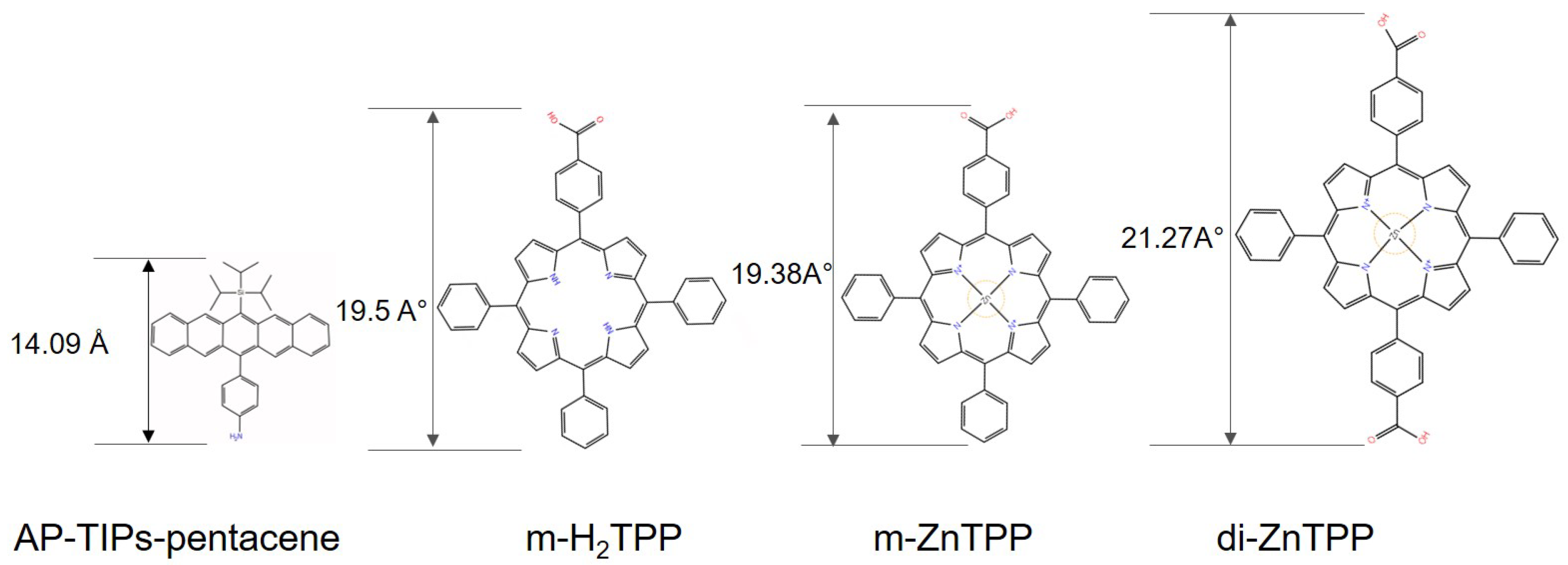
Lead quantum dots PbS-QDs have been purchased from the Quantum Solutions company with average size 6.1+/-0.9 nm and approximately 0.78 eV band energy. A cuboctahedron NCs shape with (111) and (100) facets [16,17] were capped with long aliphatic chained insulator oleic acid (OA) ligands which are typically applied during QD synthesis as stabilizing and passivating surfactants [18]. OA is replaced by different types of ligands in this work. Anchor group of Amino Phenyl (AP) added to TIPS- pentacene (6-(phenylamineethyinyl)-13-(triisopropylsilylethinyl)-pentacene) has been synthesized by Bettinger’s group in Tübingen. P b [ O l e a t e ] 2 reacts with the lone electron pair on the nitrogen of amino-phenyl N H 3 + 1 of AP-TIPS- pentacene in n-Hexan solvent to fabricate thin films of PbS-AP-TIPS-pentacene core-shell semiconductor nanoparticles. These ligands were classified according to their electrons donation to P b + 2 atoms. Ligands which donate 1 called X-type e.g. iodide, carboxylates, thiolates and 0 called Z-type like amines[19]. The neutrality and Fermi level position with respect to LUMO or HOMO level depends on the charge balance and thermodynamic stability of QDs and ligands together. Fermi level determines the semiconductor type of the final PbS- ligands films. If the ligands do not totally cover the QDs, atoms can react with oxygen atoms during or post-preparation. In that case, dangling bonds would remain at the surface. Both oxygen and dangling bonds are a source of traps. Other molecules like m H 2 T P P c a r b o x y l i c acid (5-monocarboxyphenyl-10,15, 20 - Tetraphenylporphyrin), mZnTPP-carboxylic acid (Zn-(5-monocarboxyphenyl-10,15, 20 - Tetraphenylporphyrin)) and diZnTPP-carboxylic acid (Zn-(5-dicarboxyphenyl-10,15, 20 -Tetraphenylporphyrin)) were modified with mono - and di- caboxyl (COOH) side groups. These molecules were synthesized in Toluene and Dimethylformamid (DMF). Since the carboxylic acid group dissociates upon binding to a nanocrystal surface, this results in a proton H + 1 and an oleate C O O 1 . In this case, the reaction takes place between the P b + 2 and carboxylate C O O 1 . The new ligands of mono m H 2 T P P c a r b o x y l i c acid and mZnTPP-carboxylic acid replace OA and form distinctive shells around the NCs. Subsequently, the distances among the NCs and the electronic properties also undergo transmutation depending on the ligand properties and dimensions. A cross link between two adjacent NCs is formed in the case of diZnTPP-carboxylic acid because the molecules have two carboxylic side groups. In the real space, the molecules have different confirmation shapes. One or more of their side phenyl rings can form angles in reference to the main axis of the molecules’ backbones and other corresponding rings. The Jaguar optimization tool of Schrödinger software is used to plot the molecules and the calculation of the angles. Ligand exchange was performed by spin coating one of the ligands m H 2 T P P , mZnTPP-carboxylic acid, diZnTPP-carboxylic acid and PbS-NCs layers sequentially followed by a washing process after each PbS-ligand exchange layer. PbS-NCs and AP-TIPS-pentacene were mixed and the reaction took place inside the same vial before spin-coating the layers without a washing process. For oxidization reduction, samples were prepared in a nitrogen environment inside a glove box as oxygen and hydroxyl ( O H ) were observed attached to the PbS NCs’ surface of (111) facets by Fourier-transform infrared spectroscopy (FTIR) analyzer [20]. Molecules like bathocuproine (BCP) and hexaazatriphenylenehexacarbonitrile (HATCN) were used in the normal and inverted stacks. BCP was used as an exciton blocking layer, while HATCN was used as an efficient transport layer at the reverse bias of the solar cell [21].
Figure 1. Sketches of PbS-NC and organic molecules which have been used in this research.
Preprints 92081 g001

2.2. Device Preparation

Normal and inverted stacks have been performed in this work which are illustrated in Figure 2. In the case of PbS-AP-TIPs- pentacene in the normal stack, the pentacene layer was replaced by the COINs and molecules of (C60, DBP,PTCBI and ZnPc) were used as donor layer. In the inverted stack, ethoxylated polyethylenimine (PEIE) as a buffer layer was purchased from Sigma Aldrich and spun to modify the work function of ITO [2].

2.3. Experimental Methods

Transmission electron microscopy (TEM) was performed on a JEOL Neoarm F200 with a cold field-emission gun (Cold FEG) using carbon-coated copper grids (type S160-3) from Plano (Germany), operated at 200 keV electron beam energy under vacuum. Samples were scanned under ambient atmosphere with the scanasyst mode of atomic force microscopy (AFM) from Bruker company. Ultraviolet Photoelectron Spectroscopy (UPS) was performed in ultra high vacuum (UHV) using He I radiation (21.22 eV) from a gas discharge lamp and the radiation was attenuated by passing through an aluminum foil (350 nm) before reaching the sample to minimize sample damage. Survey data was collected from X-ray photoelectron spectroscopy (XPS) using a non-monochromatic MgK α radiation (1.2536 keV). To collect radiation, a pass energy of 2.0 eV for UPS, 20 eV and 50 eV for high-resolution and survey XPS scans were used. By measuring the Fermi edge of a clean Au crystal, it was possible to determine the energy resolution and energy scale calibration. A bias of (-10V) was applied to measure the secondary electron cut-off (SECO). Photodiodes were measured with Keithley 236 SMU in the dark and under one sun simulated AM1.5G, 100 mW/cm2 illumination with a Xe lamp (Oriel 300 W with AM1.5G filters) integrated in a glove box system with nitrogen atmosphere. Current-voltage characteristics of the solar cells were measured from -1.5 V to 1.5 V in 0.05 V steps [22].

3. Results

This section summarizes the findings made about a comparison between the optoelectrical properties of four different ligands. Structure and morphology of the films were investigated using TEM and AFM. Also, the electronic structure of the energy levels were studied using ultraviolet photoelectron spectroscopy. Moreover, the electrical and impedance were measured using different set-ups like sun-simulator and PAIOS.

3.1. Transmission Electron Microscope (TEM)

Scanning transmission electron microscope imaging (Figure 3 a) reveals a scope of large PbS NCs capped with oleic acid (OA). This scope has a well-ordered distribution hexagonal domain in the first monolayer. This superlattice is initiated from the weak reaction of oleic acid with NCs and prevents them from aggregation. A hexagonal superlattice structure (Figure 3 d) of PbS-AP-TIPS-pentacene affirms a weak interaction between the amino phenyl anion and NCs with full ligand replacement of OA. This one-sided ligand interaction with NCs shows similar distances among the NCs at the first monolayer that equals to the double size of AP-TIPS-pentacene molecule with slight differences in some positions because of molecules’ overlap or different molecule shape confirmations. Furthermore, a transition in lattice orientation among different block domains combines phenomenally. A full shift of PbS-NCs’ correlation among the monolayers predicts a complete packed film for thicker layers. This is verified by atomic force microscope Figure 4. In the case of H2-TPP Figure 3 e, although the sample shows disorder distribution, it is crucial to confirm it because of the sample prepartion difficulty. Figure 3f and g reveal also a hexagonal structure for NCs capped with mZnTPP-carboxylic acid and diZnTPP-carboxylic acid ligands with less order than PbS-AP-TIPS-pentacene. These ligands form carboxylate-NCs after the ligand exchange process. Essentially, the film quality depends quantitatively on the ligand exchange process. The average measured distance among the NCs in the case of mZnTPP-carboxylic acid is found to be (1.8 nm) from the live profile tool using the GATAN program which is very close to the ligand size (1.9nm). Actually, a double molecule size distance was expected from this ligand. On the other hand, the STEM image in Figure 3 g of diZnTPP-carboxlate-PbS NCs reveals an average distance equal to 2.7 nm while molecule size is 2.1 nm. A similar range (1-6 nm) of spacial spaces among the NCs is measured for both mZnTPP-carboxylic acid and diZnTPP-carboxylic acid using different techniques with GATAN software. These techniques are amply illustrated in the supporting information file. This can be concluded from the discordant distances among NCs where the disharmonized distribution is observed with divergence in different spots. However, this could initiate from the sample preparation and washing process. Several lattice planes were distinguished for the PbS-QDs such as (200), (111), (110), (220) and etc. There were other lattices planes detected from the diffraction pattern of fast Fourier transform (FFT) which are illustrated in the supporting file.

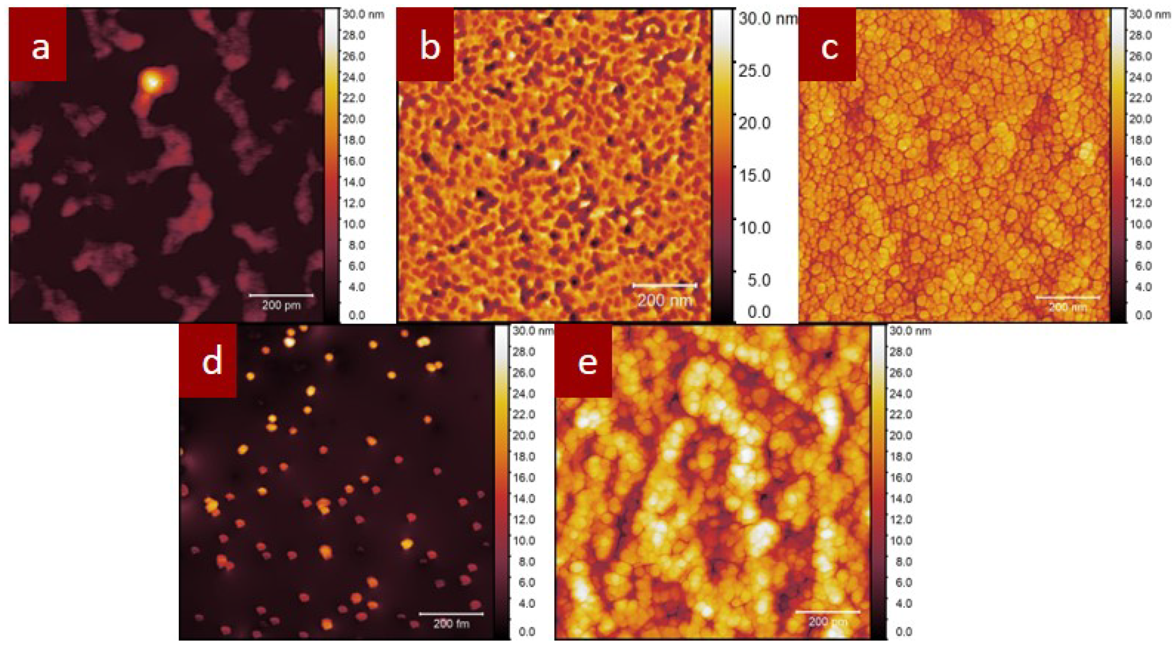
3.2. Atomic Force Microscope (AFM)

AFM images of PbS-ligands are shown in Figure 4. Average thicknesses and roughness are listed in Table 1 for disparate COINs. A complete COINs coverage in samples (Figure 4 b - c and e) are formed. Nonetheless, the roughness and grain sizes are different as illustrated in Table 1. These COINs are the outgrowth of the early monolayers which have been demonstrated in TEM images. The AP-TIPS-pentacene formed a smoother film as a result of superlattice monolayers. On the other hand, indivdual islands are illustrated in Figure 4d because COINs’ substances have been removed during the washing process which give an indication of weak adhesion between COINs and the substrate. In the case of PbS-mZnTPP, COINs are grown in three-dimensional clusters.

4. Electrical Characteristics

4.1. AP-TIPS-Pentacene

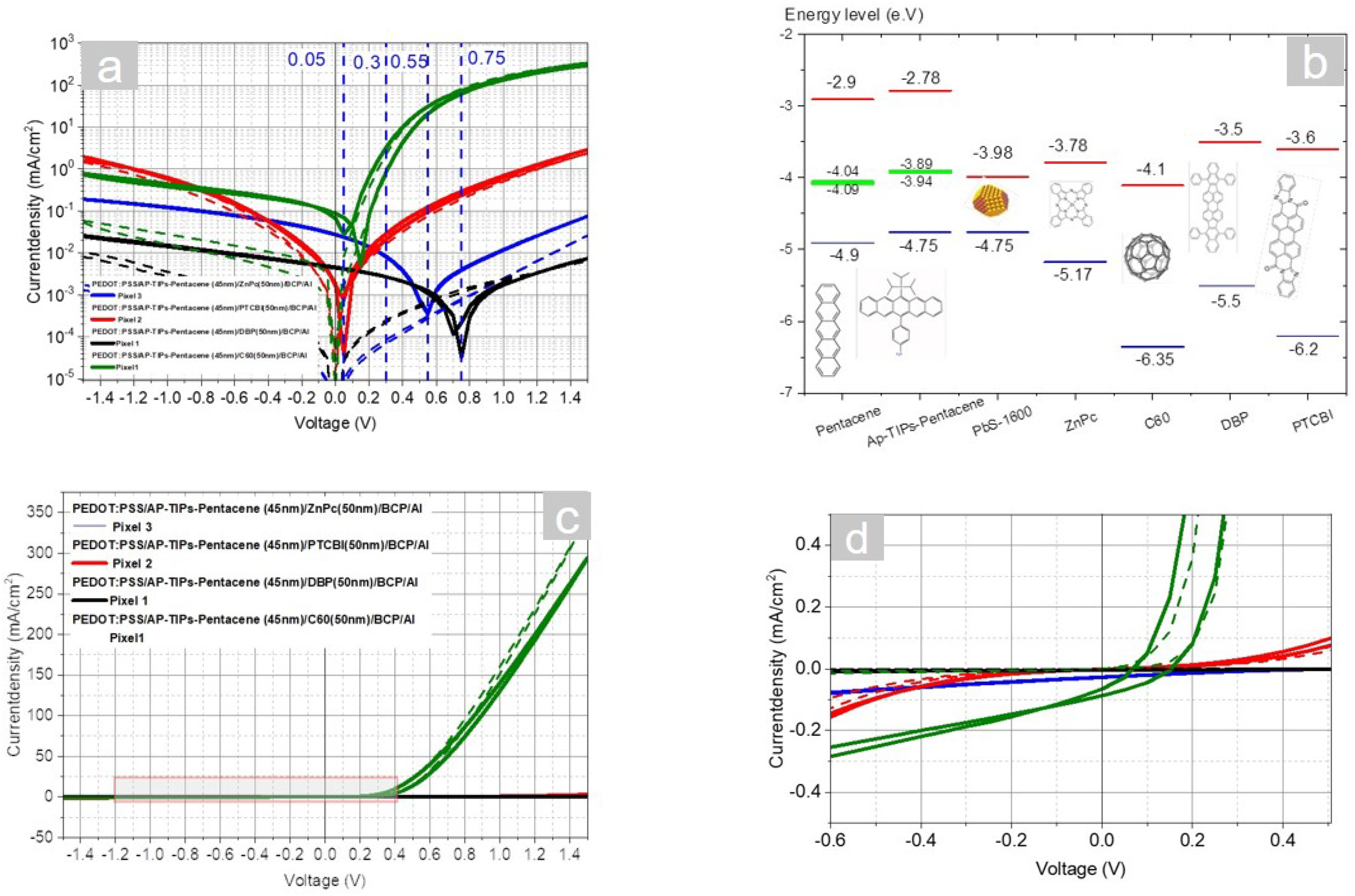
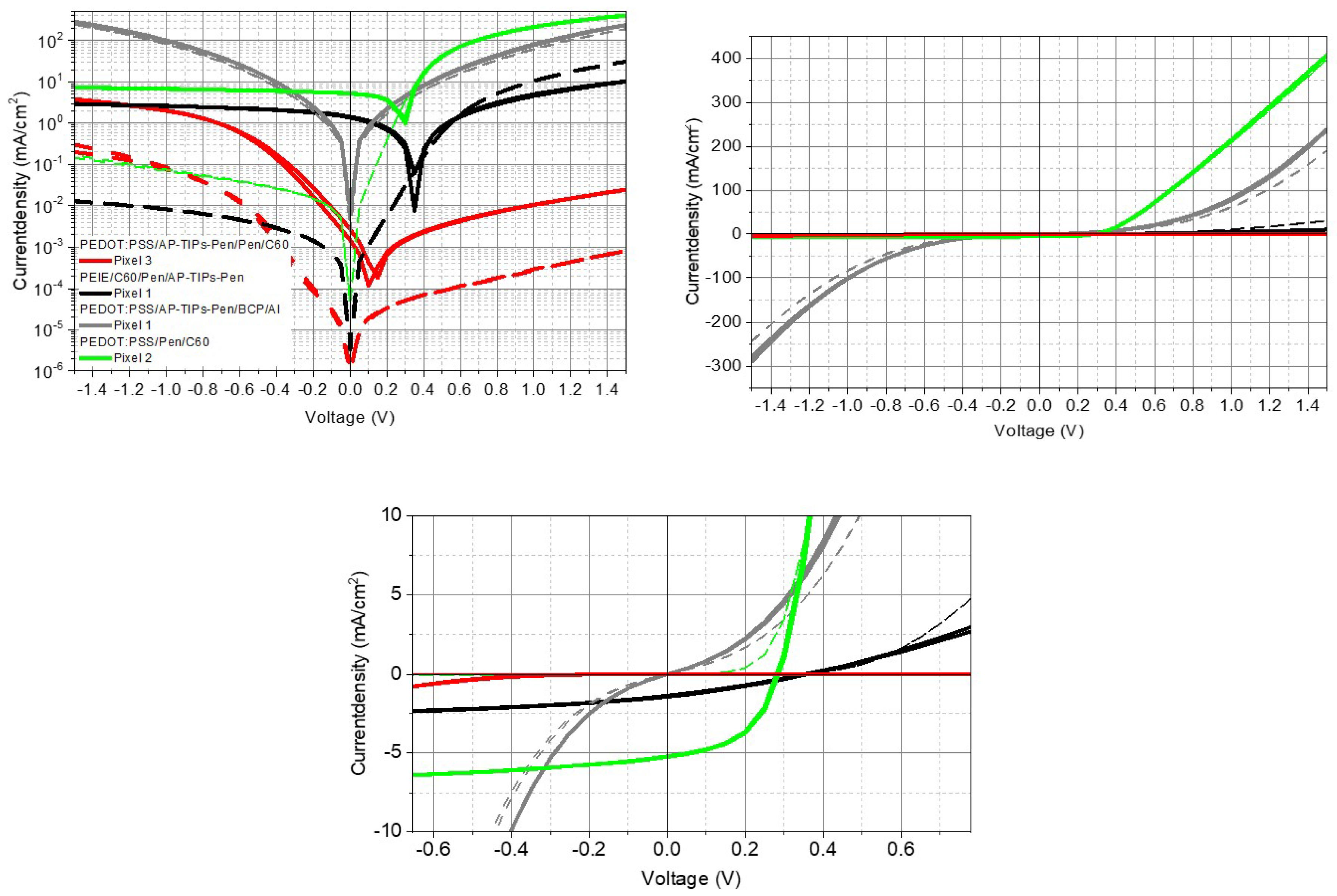
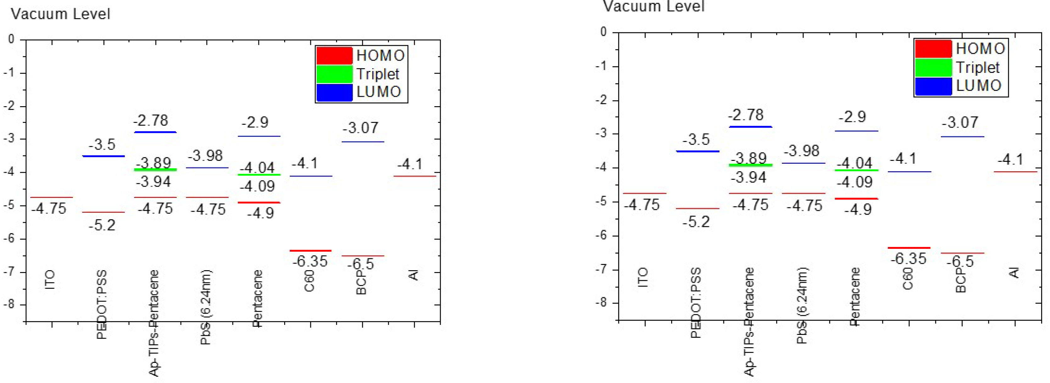
Neotric organic molecules (amino-phynel-TIPS-pentacene) were synthesized to bring the organic nanoparticles closer to the NCs. This was done as an enhancement to collect the excitons and for better charge carrier separation. The unique molecule surpasses the short previous ligands because it uniformly makes a shell around the NCs to form a film with superlattice structure. That means, the new ligand react with all QDs’ facets equally and it has no preferable facet. The final morphology under AFM shows a very smooth surface. It was necessary to look for a nominated acceptor to use the current COINs in a solar cell. Several molecules ( C 60 , DBP, ZnPc and PTCBE) were tested. HOMO-LUMO level of the new PbS-AP-TIPS- pentacene were assigned according to the UPS measurement in Figure 5. The triplet state is assigned by assuming the same distance from the HOMO level of the original pentacene molecule. The C 60 molecule has a clear current injection region in the forward bias and high short circuit current, better photo- to dark current ratio in the reverse bias. DBP has the highest open circuit voltage. However, the injection current is not clear in this graph because it is lying beyond 1.5 V. Other molecules’ parameters are lying in between C 60 and DBP, taking into account that the source of the light is unstable. The intensity is varying between (86 and 119 mW/cm2). Losses in energy between the HOMO of COINs and LUMO of the acceptors are calculated and illustrated in Table 3.

4.2. AP-TIPS-pentacene- Single Carrier Devices

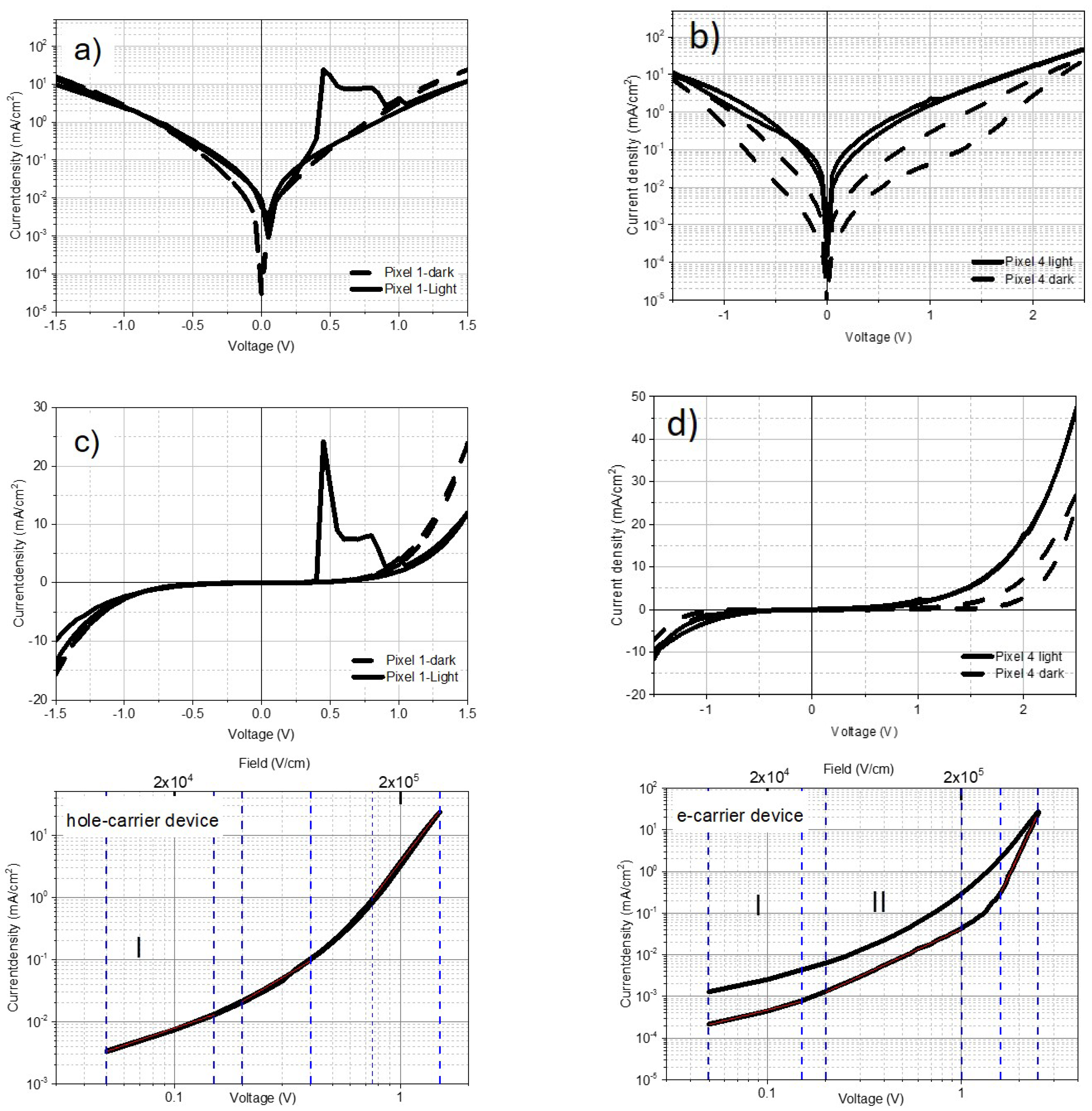
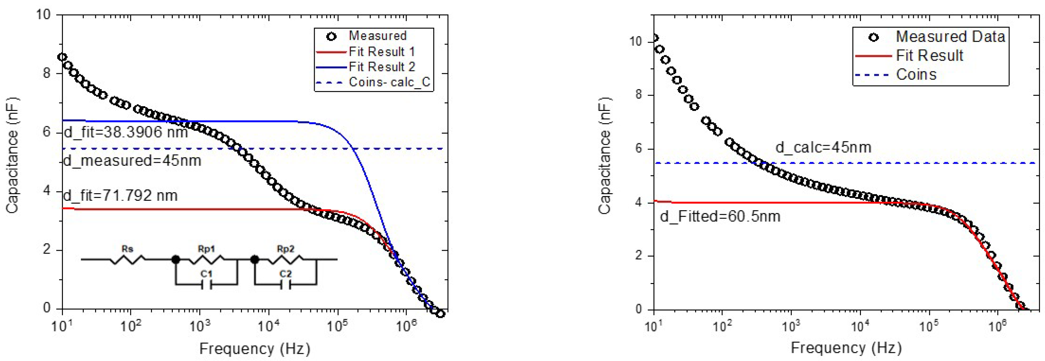
Single carrier devices in Figure 6 show unexpected behavior that the photocurrent of the hole carrier device is lower than the dark current. The capacitance-voltage graph in Figure 7 reveals a step plateau which is an indication of charge accumulation at a certain interface of the stack. This could be initiated from the holes’ accumulation at the COINs-HATCN interface. The equivalent electrical circuit is plotted to explain the step frequency response. However, the superlattice structure of PbS and AP-TIPS-pentacene leads to single carrier devices for both electrons and holes without a clear trap charge limited current region which are shown in log-log scale in Figure 6. Because AP-TIPS-pentacene has a semiconductor band gap, longer than EDT and its weak interaction with NCs, that generates intirnsic carriers with 10 16 c m 3 concentration. It was possible to calculate the mobility of both electron and holes as seen in Table 4.
It is possible to measure the capacitance of individual QDs from the modified Laikhtman–Wolf model [15,23]:
C S 1 = 1 4 π ε 0 r ε QD ε matrix ε QD . ε matrix + 0.94 4 π ε QD ε 0 r ε QD ε matrix ε QD + ε matrix
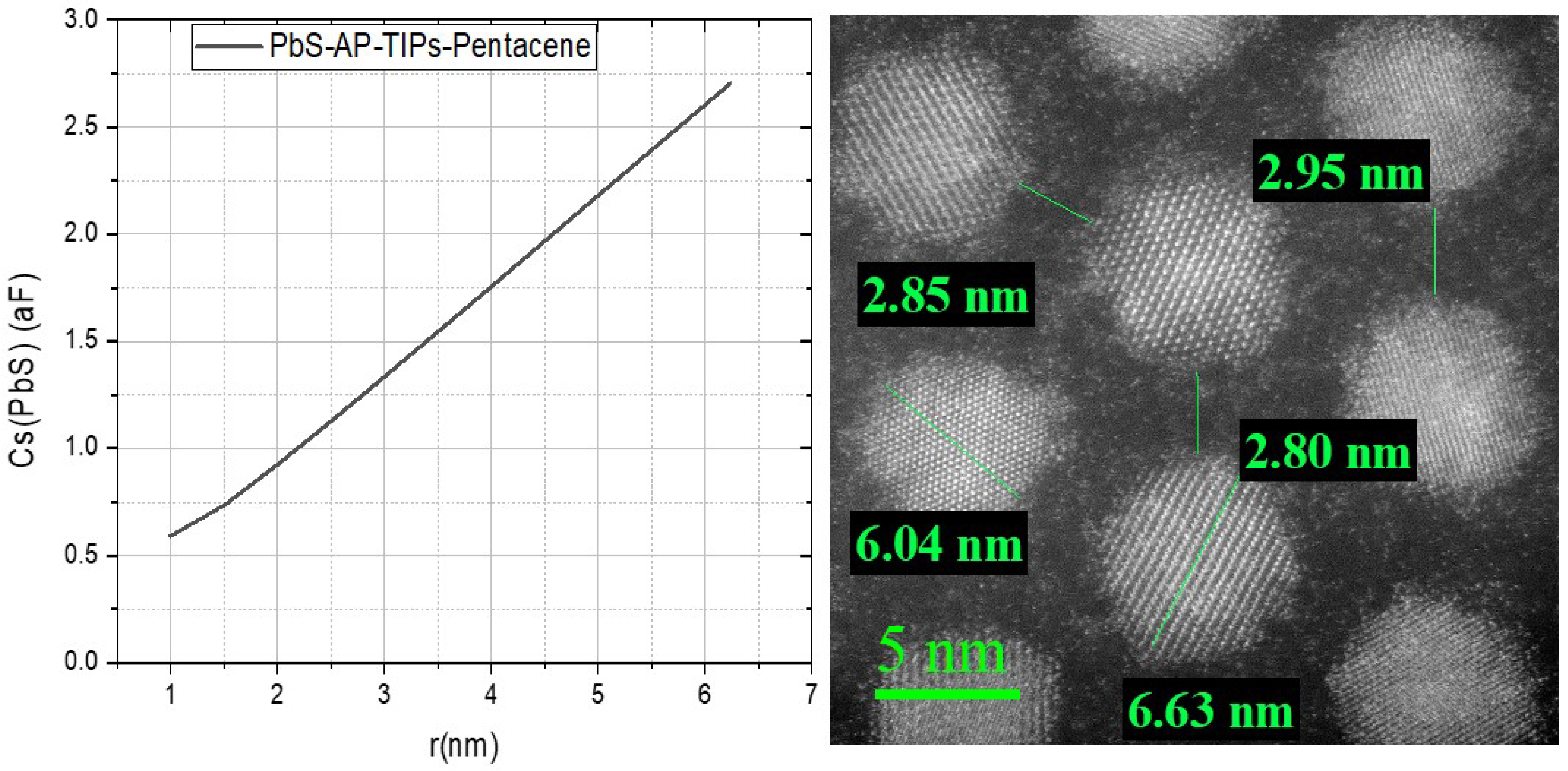
r is the distance between the PbS QDs center to center, C S is the capacitance of individual nanoparticles, ε QD is the dielectric constant of individual quantum dot, ε matrix is the dielectric constant of COINs layer. We assume that the average distance between NCs in Figure 7 b is D=10.11nm. There are 2 x 10 28 QDs in an area of 2 m m 2 . The height distance =2r between the layers. Therefore, Cs= 1.08 nF for one monolayer whereas total Cs in the film of 45 nm thickness is 3.9nF. This value is very close to the first step plateau in the hole CF measurement. Figure 7 represents the difference of the calculated capacitance for individual QDs in COINs with EDT and AP-TIPS-pentacene versus QDs’ sizes. The importance of having superlattice layers upon the disordered distribution of the QDs is observed here. The difference reflects the effective QD contribution inside the AP-TIPS-pentacene COINs which allow them to be charged to the maximum inspite of the fact that QDs in EDT are denser.

4.3. Difference between Normal and Inverted stack

PbS-AP-TIPS-pentacene has been added to pentacene/ C 60 solar cells in the normal and inverted stacks. The JV characteristic of these solar cells are shown in Figure 9. The double hetrojunction solar cell (PbS-AP-TIPS-pentacene/ C 60 ) shows unexpected behavior in the normal stack. The forward current is lower than the reverse bias for both dark and under illumination. It is important to mention that we assumed PbS-AP-TIPS-pentacene is a one layer when we assigned the energy level diagrams in Figure 5. The JV characteristics set back this hypothesis and the LUMO level of QDs can play the role of an electron blocking layer between pentacene and the new COINs. However, the charge separation is still at a high level from the photo to dark current ratio. We can imagine the opposite where a barrier can be inserted between the COINs and HATCN in the inverted stack. This was clarified by the forward bias in Figure 6 and the step plateau of CF in Figure 7. The leakage current is very low which suggested high shunt resistance and lower trap concentrations. The COINs alone in a normal stack did show a resistance behavior but there is no charge separation. That means, these COINs need an acceptor layer for solar cell operation.

4.4. Tetraphenylporphyrin Ligands-TPP

Our previous results and conclusions paved the way to look for other ligands which can form COINs with LUMO level and with an optical energy level lying under the triplet state of pentacene. In addition, these molecules must have suitable length, semiconductor properties and can covalently be bound to PbS-QDs. Therefore, we selected a Tetraphenylporphyrin molecule from the publication [24] and its derivative with a zinc metal core. Mono and di-carboxylic acid was added to the molecule to form m H 2 TPP-carboxylic acid, mZnTPP-carboxylic acid, and diZnTPP-carboxylic acid. Figure 11 reveals three different diodes. However, their detection of light is lower that what has been observed in AP-TIPS-pentacene. This information reinforces the hypothesis which we theorize is related to the distance between QDs and pentacene. The novel COINs have only one line parallel with pentacene molecules at the interface. Hence, many generated excitons in the bulk of pentacene would recombine without having the chance to transfer them to the QDs. However, further research needs to be done with the ligands under study. Retracing to JV, all types of the new ligands show injection current above 1.2 V in the forward bias. There is low shunt resistance which causes high leakage current in the reverse bias. COINs with m H 2 -TPP ligands has the highest current as expected.
Table 6. Solar cell parameters for inverted stack PEIE/PbS(Abs.peak=1600nm)-ligands (4 layers)/pen/HATCN/Au.
Sample Pixel J sc V oc FF Efficiency
- - mA/cm2 V - Percent
m-Zn-TPP 2 -0.01621 0.45009 0.32815 0.00281
di-Zn-TPP 4 -0.02813 0.24074 0.24811 0.00198
m H 2 -TPP 2 -0.01153 0.20961 0.31217 8.795E-4

References

  1. Scheele, M.; Hanifi, D.; Zherebetskyy, D.; Chourou, S.T.; Axnanda, S.; Rancatore, B.J.; Thorkelsson, K.; Xu, T.; Liu, Z.; Wang, L.W.; et al. PbS nanoparticles capped with tetrathiafulvalenetetracarboxylate: utilizing energy level alignment for efficient carrier transport. ACS nano 2014, 8, 2532–2540. [Google Scholar] [CrossRef] [PubMed]
  2. Ehrler, B.; Wilson, M.W.B.; Rao, A.; Friend, R.H.; Greenham, N.C. Singlet exciton fission-sensitized infrared quantum dot solar cells. Nano letters 2012, 12, 1053–1057. [Google Scholar] [CrossRef] [PubMed]
  3. Smith, M.B.; Michl, J. Singlet fission. Chemical reviews 2010, 110, 6891–6936. [Google Scholar] [CrossRef] [PubMed]
  4. Papa, C.M.; Garakyaraghi, S.; Granger, D.B.; Anthony, J.E.; Castellano, F.N. TIPS-pentacene triplet exciton generation on PbS quantum dots results from indirect sensitization. Chemical science 2020, 11, 5690–5696. [Google Scholar] [CrossRef] [PubMed]
  5. Garakyaraghi, S.; Mongin, C.; Granger, D.B.; Anthony, J.E.; Castellano, F.N. Delayed molecular triplet generation from energized lead sulfide quantum dots. The journal of physical chemistry letters 2017, 8, 1458–1463. [Google Scholar] [CrossRef] [PubMed]
  6. Pun, A.B.; Asadpoordarvish, A.; Kumarasamy, E.; Tayebjee, M.J.Y.; Niesner, D.; McCamey, D.R.; Sanders, S.N.; Campos, L.M.; Sfeir, M.Y. Ultra-fast intramolecular singlet fission to persistent multiexcitons by molecular design. Nature chemistry 2019, 11, 821–828. [Google Scholar] [CrossRef] [PubMed]
  7. Ganesan, A.A.; Houtepen, A.J.; Crisp, R.W. Quantum dot solar cells: Small beginnings have large impacts. Applied Sciences 2018, 8, 1867. [Google Scholar] [CrossRef]
  8. Hu, J.; Xu, K.; Shen, L.; Wu, Q.; He, G.; Wang, J.Y.; Pei, J.; Xia, J.; Sfeir, M.Y. New insights into the design of conjugated polymers for intramolecular singlet fission. Nature communications 2018, 9, 1–9. [Google Scholar] [CrossRef] [PubMed]
  9. Dai, Z.; Yadavalli, S.K.; Chen, M.; Abbaspourtamijani, A.; Qi, Y.; Padture, N.P. Interfacial toughening with self-assembled monolayers enhances perovskite solar cell reliability. Science 2021, 372, 618–622. [Google Scholar] [CrossRef]
  10. Brown, P.; Kim, D.; Lunt, R.; Bawendi, M.; Grossman, J.; Bulovic, V. Energy level modification in lead sulfide quantum dot photovoltaics through ligand exchange. APS 2014, 2014, L24–002. [Google Scholar] [CrossRef]
  11. Tabachnyk, M.; Ehrler, B.; Gélinas, S.; Böhm, M.L.; Walker, B.J.; Musselman, K.P.; Greenham, N.C.; Friend, R.H.; Rao, A. Resonant energy transfer of triplet excitons from pentacene to PbSe nanocrystals. Nature materials 2014, 13, 1033–1038. [Google Scholar] [CrossRef]
  12. Davis, N.J.L.K.; Allardice, J.R.; Xiao, J.; Petty, A.J.; Greenham, N.C.; Anthony, J.E.; Rao, A. Singlet fission and triplet transfer to PbS quantum dots in TIPS-tetracene carboxylic acid ligands. The journal of physical chemistry letters 2018, 9, 1454–1460. [Google Scholar] [CrossRef] [PubMed]
  13. Hu, L.; Mandelis, A.; Yang, Z.; Guo, X.; Lan, X.; Liu, M.; Walters, G.; Melnikov, A.; Sargent, E.H. Temperature-and ligand-dependent carrier transport dynamics in photovoltaic PbS colloidal quantum dot thin films using diffusion-wave methods. Solar Energy Materials and Solar Cells 2017, 164, 135–145. [Google Scholar] [CrossRef]
  14. Liu, Y.; Gibbs, M.; Puthussery, J.; Gaik, S.; Ihly, R.; W. Hillhouse, H.; Law, M. Dependence of Carrier Mobility on Nanocrystal Size and Ligand Length in PbSe Nanocrystal Solids. Nano Lett 2010, 10, 1960–1969. [CrossRef] [PubMed]
  15. Scheele, M.; Brütting, W.; Schreiber, F. Coupled organic-inorganic nanostructures (COIN). Physical Chemistry Chemical Physics 2015, 17, 97–111. [Google Scholar] [CrossRef] [PubMed]
  16. Choi, H.; Ko, J.H.; Kim, Y.H.; Jeong, S. Steric-hindrance-driven shape transition in PbS quantum dots: understanding size-dependent stability. Journal of the American Chemical Society 2013, 135, 5278–5281. [Google Scholar] [CrossRef] [PubMed]
  17. Beygi, H.; Sajjadi, S.A.; Babakhani, A.; Young, J.F.; van Veggel, F.C.J.M. Surface chemistry of as-synthesized and air-oxidized PbS quantum dots. Applied Surface Science 2018, 457, 1–10. [Google Scholar] [CrossRef]
  18. Heuer-Jungemann, A.; Feliu, N.; Bakaimi, I.; Hamaly, M.; Alkilany, A.; Chakraborty, I.; Masood, A.; Casula, M.F.; Kostopoulou, A.; Oh, E.; et al. The role of ligands in the chemical synthesis and applications of inorganic nanoparticles. Chemical reviews 2019, 119, 4819–4880. [Google Scholar] [CrossRef]
  19. Giansante, C.; Infante, I. Surface traps in colloidal quantum dots: a combined experimental and theoretical perspective. The journal of physical chemistry letters 2017, 8, 5209–5215. [Google Scholar] [CrossRef]
  20. Tom, A.E.; Thomas, A.; Ison, V.V. Novel post-synthesis purification strategies and the ligand exchange processes in simplifying the fabrication of PbS quantum dot solar cells. RSC Advances 2020, 10, 30707–30715. [Google Scholar] [CrossRef]
  21. Falkenberg, C.; Olthof, S.; Rieger, R.; Baumgarten, M.; Muellen, K.; Leo, K.; Riede, M. The role of energy level matching in organic solar cells—Hexaazatriphenylene hexacarbonitrile as transparent electron transport material. Solar Energy Materials and Solar Cells 2011, 95, 927–932. [Google Scholar] [CrossRef]
  22. Brütting, W.; Riel, H.; Beierlein, T.; Riess, W. Influence of trapped and interfacial charges in organic multilayer light-emitting devices. Journal of Applied Physics 2001, 89, 1704–1712. [Google Scholar] [CrossRef]
  23. Laikhtman, B.; Wolf, E.L. Tunneling time and effective capacitance for single electron tunneling. Physics Letters A 1989, 139, 257–260. [Google Scholar] [CrossRef]
  24. Liao, M.S.; Scheiner, S. Electronic structure and bonding in metal porphyrins, metal= Fe, Co, Ni, Cu, Zn. The Journal of chemical physics 2002, 117, 205–219. [Google Scholar] [CrossRef]
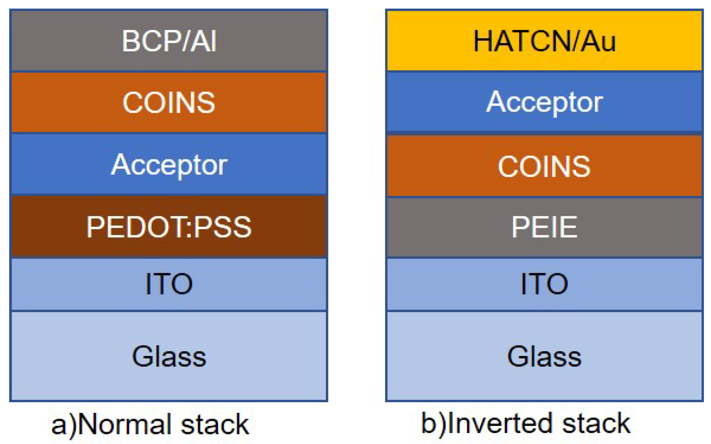
Figure 2. Shows the sample stacks, pixel size is 2 x 2 m m 2 a) normal stack and b) inverted stack.
Preprints 92081 g002
Figure 3. STEM images of a) PbS-OA, b) PbS-AP-TIPS-pentacene, c) m H 2 T P P c a r b o x y l a t e P b S , d) mZnTPP-carboxylate-PbS and e) diZnTPP-carboxylate-PbS.
Preprints 92081 g003
Figure 4. AFM for a) PbS-OA, b) PbS AP-TIPS-pentacene, c) H 2 T P P , d) PbS-mZnTPP-carboxylate and e) diZnTPP-carboxylate, respectively.
Preprints 92081 g004
Figure 5. a),c) and d)J-V characteristics of Amino phynel TIPS-pentacene with different acceptors b) represents the energy level diagrams of pentacene, Amino phynel TIPS-pentacene and different acceptors.
Preprints 92081 g005
Figure 6. Logarithmic scale and linear scale of a),c),e) hole carrier device and b),d),f)electron carrier device of AP-TIPS-pentacene.
Preprints 92081 g006
Figure 7. Capacitance versus frequency for a) hole and b) electron single carrier devices of AP-TIPS-pentacene.
Preprints 92081 g007
Figure 8. QDs capacitance versus PbS-QDs radius for EDT and AP-TIPS-pentacene ligands.
Preprints 92081 g008
Figure 9. Difference between normal and inverted stack by spinning PbS-AP-TIPS pentacene as an extra layer on Pentacene/ C 60 solar cells.
Preprints 92081 g009
Figure 10. Energy levels of PbS-AP-TIPS with pentacene/ C 60 solar cell in a) normal stack and b) inverted stack.
Preprints 92081 g010
Figure 11. Inverted stack of three different types of ligands: m H 2 -TPP, mZnTPP and diZnTPP.
Preprints 92081 g011
Table 1. Film parameters for different PbS-ligands
COINs Thickness (nm) Roughness (nm)
PbS-AP-TIPS-pentacene 45 1.582
P b S m H 2 c a r b o x y l a t e 28 3.77
PbS-mZnTPP-carboxylate 3 0.6
PbS-diZnTPP-carboxylate 26 5.239
Table 2. Solar cell parameters for normal stack, PEDOT:PSS/AP-TIPS-Pen(45nm)/acceptors(50nm)/BCP(5nm)/Al.
Sample Pixel J sc V oc FF Efficiency
- - mA/cm2 V - percent
ZnPc 3 -0.02355 0.53362 0.19046 0.00278
PTCBI 2 -0.00168 0.04165 0 0
DBP 1 -0.00419 0.73612 0.25642 8.43E-4
C 60 1 -0.09152 0.11048 0.30928 0.00293
Table 3. Losses in energy difference between HOMO-LUMO in comparison to e V oc for PbS-AP-TIPS-pentacene/acceptors.
Sample Δ E ( e . V ) , E LUMO E HOMO V oc (V) Δ E Loss (e.V)
ZnPc 0.97 0.65 0.32
PTCBI 1.15 0.35 0.8
DBP 1.25 0.9 0.35
C 60 0.65 0.06-0.15 0.59-0.5
Table 4. Intrinsic and electron(hole) mobility of AP-TIPS- pentacene.
Sample Electron mobility Hole mobility n i
- c m 2 / V . s c m 2 / V . s c m 3
PbS-AP-TIPS-pentacene (1600nm) 1.63 x 10 5 - 3.95 x 10 16
PbS-AP-TIPS-pentacene (1600nm) - 9.76 x 10 5 2.91 x 10 16
Table 5. Solar cell parameters for normal stack PEDOT:PSS/AP-TIPS-Pen(45nm)/Pen(50nm)/ C 60 (50nm)/BCP(5nm)/Al and inverted stack PEIE/ C 60 /Pen/Ap-TIPS-Pen/HATCN/Au
Sample Pixel J sc V oc FF Efficiency
- - mA/cm2 V - Percent
Normal Stack
COINs/Pen/ C 60 3 -0.00168 0.12403 0.19263 5.035E-5
COINs/BCP/Al 1 -0.00674 0.001 0.00E+00 0
Pen/ C 60 2 -5.16213 0.28292 0.50081 0.73877
Inverted Stack
C 60 /Pen/COINs 1 -1.10365 0.35154 0.2856 0.13655
Disclaimer/Publisher’s Note: The statements, opinions and data contained in all publications are solely those of the individual author(s) and contributor(s) and not of MDPI and/or the editor(s). MDPI and/or the editor(s) disclaim responsibility for any injury to people or property resulting from any ideas, methods, instructions or products referred to in the content.
Copyright: This open access article is published under a Creative Commons CC BY 4.0 license, which permit the free download, distribution, and reuse, provided that the author and preprint are cited in any reuse.
Prerpints.org logo

Preprints.org is a free preprint server supported by MDPI in Basel, Switzerland.

Subscribe

© 2024 MDPI (Basel, Switzerland) unless otherwise stated