1. Introduction
A flywheel is a rotational device that stores rotational energy as it spins. When this energy can be converted into electrical energy, it is called an electromechanical battery [
1,
2,
3] which, in the simplest way, is referred to as the first generation. The second generation incorporates an AC generator, an inverter and a rectifier. If it reaches the power grid and the flow of energy can be reversed, it becomes a Flywheel Energy Storage System (FESS) [
2,
3]. The third generation [
3,
4,
5,
6] includes more characteristics (magnetic bearings, vacuum, etc). New and expensive materials can improve the range of energy storage, but as they are expensive it is desirable to increase the stored energy density through new geometries.
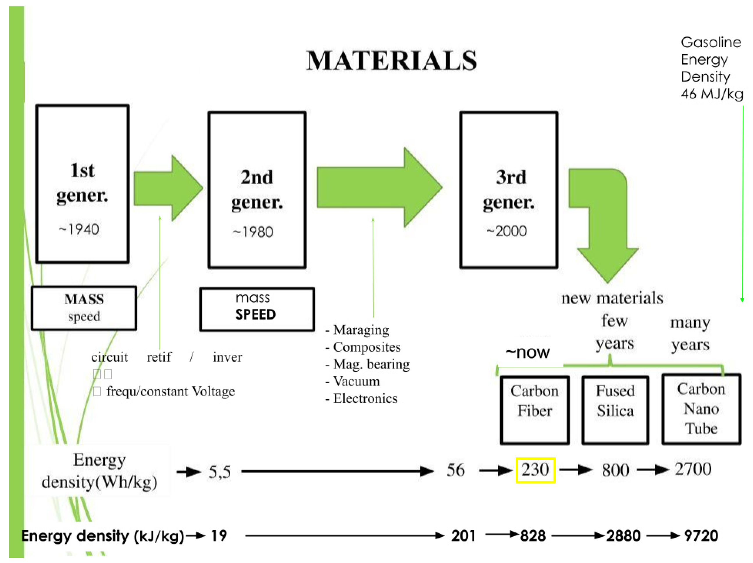
Figure 1 shows the evolution of the flywheel generations [
2,
3,
4]. It also shows that the important goal at the present is to reach a very high energy density storage. As can be seen in the figure, the energy density depends on the material that is used to fabricate the flywheel. For instance if the flywheel could be made of carbon nanotubes (CNT) it could reach an energy density that is about 20% of gasoline’s energy density, if an efficiency of 20% is considered for a combustion engine and an efficiency of 99% is considered for flywheels; therefore, their performances could be quite close.In this case, such flywheels could perhaps replace gasoline tanks as energy storage devices. They could even be used in aeroplanes.
Other electrical properties of Flywheels are very important but let’s consider that they are advanced enough at present to fulfil the requirements.
To reach such a goal many simulations using finite elements method (FEM) with a variety of geometries were made using the von Mises criterion to determine the maximum allowed stress on the Flywheel, followed by simulations of the normal vibration modes to verify the rotational stability of the system.
The rotational energy density in a flywheel is estimated by the formula [
7,
8,
9]:
where E is the rotational energy stored, m is the mass of the rotating flywheel,
max is the material’s ultimate tensile stress and
is the material’s specific mass. Using equation (1), in
Table 1 examples are shown of energy densities for different materials [
8,
10]. The material used in the simulations of this work appears in the last line of
Table 1: Carbon-Fiber-Hexcel-UHM-12000.
Figure 1.
The figure presents the evolution of flywheels with emphasis in the fabrication material. Flywheels made of Carton NanoTubes (CNT) are expected to store energy at the rate of one fifth of gasoline’s storage; however, taking into account the efficiency, the former might equalise with the latter. Source: The authors.
Table 1.
Materials used in the fabrication of flywheels. Data from [
8], except Hexcel UHM Carbon Fibre 12000 (source MatWeb [
10]). Results shown in the last column were calculated from eqn. (1).
Table 1.
Materials used in the fabrication of flywheels. Data from [
8], except Hexcel UHM Carbon Fibre 12000 (source MatWeb [
10]). Results shown in the last column were calculated from eqn. (1).
| Material |
Ultimate tensile
Stress (MPa) |
Specific mass
(kg/m3) |
Flywheel energy density (Wh/kg) |
| 7075 Aluminium |
572 |
2810 |
28 |
| 17-7 PH Stainless steel |
1650 |
7800 |
29 |
| Ti-15V-3Cr-3Al-3Sn ST 790 °C |
1380 |
4760 |
40 |
| E-glass (glass-fibre) laminated |
~1400 |
2146 |
90 |
| T1000G laminated (Toray) |
3040 |
1800 |
234 |
| T1000G fibre only (Toray) |
6370 |
1800 |
491 |
| Carbon-Nano-Fibres |
2920 |
2000 |
202 |
| Carbon-Fiber-Hexcel-UHM-12000 |
3730 |
1870 |
277 |
Coppede [
11] performed simulations using a finite-element analysis of flywheels made of two materials: Maraging steel (AISI 18 Ni 350) and carbon fibre (Hexcel UHM 12000), with carbon fibre as a reinforcement. His main result indicates that the best option is to make the flywheel only with carbon fibre, as can be seen in
Figure 2.
This work presents a series of simulations with the intention to optimise the rotational energy density that can be stored in a flywheel, also analysing the stability of the system under high rotational speeds. The second section describes materials and methods used during the simulations. In the third section the results for maximum rotational speed and the von Mises stress distribution are presented. Later in the same section the simulations about stability using vibrational modes are presented and some solution for a stability problem is presented. The fourth section presents a discussion about the results.
Figure 2.
Several FEM simulations were performed using flywheels made of Maraging steel, carbon fibre and Maraging steel revested with carbon fibre. The figure shows the total rotational energy (in J): in green is the rotational energy in the Maraging steel and in blue is the rotational energy in the carbon fibre. From the left to right: pure Maraging steel, then the carbon fibre revestment was increased to finally a rotor of pure carbon fibre. The best result was achieved with pure carbon fibre. Source: [
10].
2. Materials and Methods
The authors have experience with instrumentation [
12,
13,
14], which aided in the development of this work. A variety of flywheels were simulated by finite element modelling using SOLIDWORKS [
15] with geometries studied by Coppede and Nogueira [
11,
16]. The adopted FEM simulation characteristics are shown in
Table 2. The characteristics of carbon fibre Hexcel UHM 12000 appear in reference [
10]; there are new carbon fibres with more resistance but the resistance was kept the same to allow comparison.
Some of the authors have experience with detection of gravitational waves [
17], with many works using SOLIDWORKS [
18,
19,
20,
21].
Table 2.
Finite Elements characteristics.
Table 2.
Finite Elements characteristics.
| Type-of-Analysis |
static analysis |
| Type-of-Meshing |
solid |
| Thermal-effect |
activated |
| Load-type |
centrifugal |
| Connector-Support-type |
bearing |
3. Results
3.1. First Analysed Models
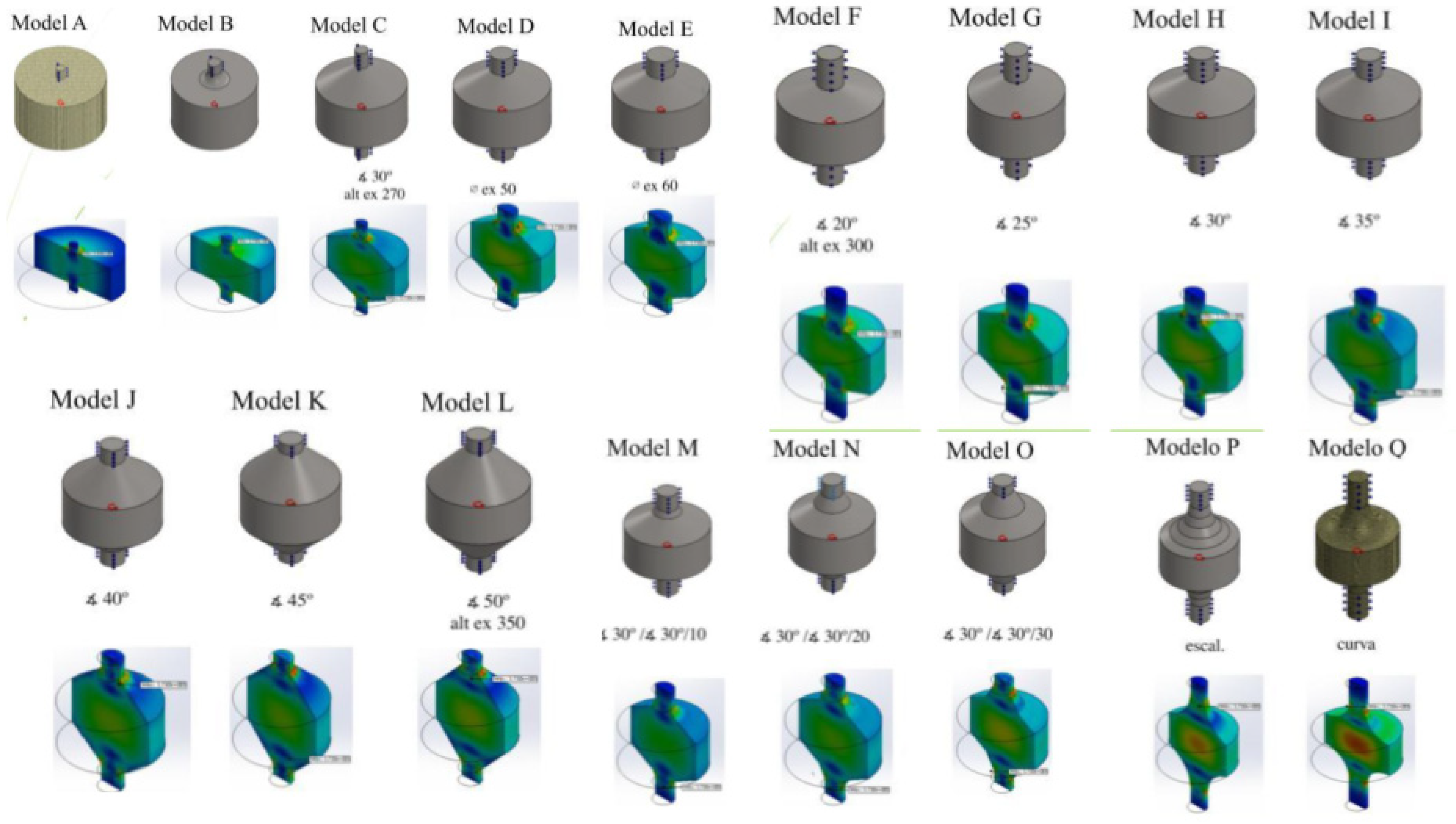
The simulations presented below are characterised as solid cylindrical bodies. All geometries are generally cylindrical with 200 mm of external diameter and about 100 mm of height. The results of the simulations are shown in
Figure 3 and
Table 3.
As the Q model presented a better behaviour and there was an indication that to increase the energy density the model needed to present a more uniform distribution in tensile stress, then a model with 180 mm of external diameter and 130 mm of height was developed, with a shape defined by the revolution of a Gaussian curve, justified next.
Following the sequence of the changes in the geometry, it is known that the best outcome results from the geometry that makes the stress get more homogeneous in the rotor. It seems quite reasonable that the best result will be reached if the whole section of the rotor experiences maximum stress. A calculation was made and the shape that allows this condition is a Gaussian shape, with formula
where ρ is the mass density, ω is the rotational velocity and σ is the resistance stress.
This Gaussian parameter was the one defined by Stodola [
22], which is the formulation for a disk with constant stress, where the exponential squared parameter is the ratio of the squared rotational speed times specific mass divided by 2 times the ultimate tensile stress. This model is denominated
R, where the central shaft with 20 mm diameter extends a further 20 mm on each side of the flywheel (see
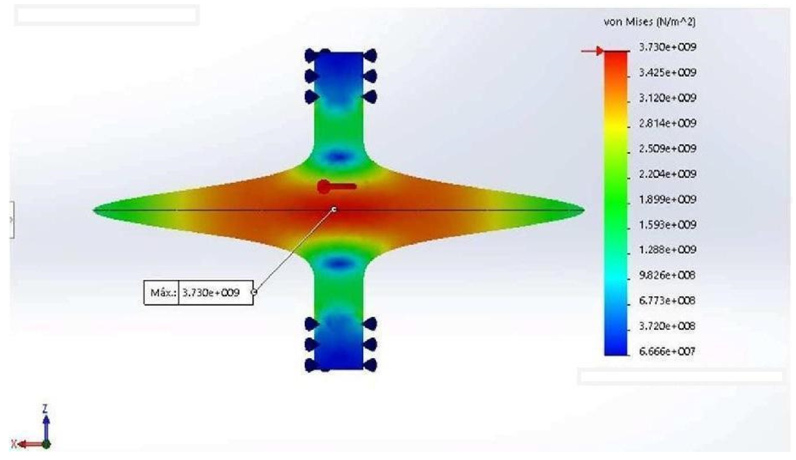
Figure 3). In
Table 3 the results of all simulations can be found. The new model
R (
Figure 3) shows for highest rotation and energy density the best results, as the total energy and mass depend on the size of the flywheel.
Figure 3.
Von Mises stress for the R model. Source: the authors.
Figure 3.
Von Mises stress for the R model. Source: the authors.
Table 3.
Results of the simulations for different flywheel models. The best results are bolded.
Table 3.
Results of the simulations for different flywheel models. The best results are bolded.
| Model |
Maximum rotation speed (RPM) |
Mass (kg) |
Stored energy (Wh) |
Energy density (Wh/kg) |
| A |
162000 |
5.89 |
1176 |
199 |
| B |
153000 |
6.02 |
1053 |
175 |
| C |
167000 |
8.23 |
1528 |
185 |
| D |
192000 |
8.4 |
2042 |
243 |
| E |
185000 |
8.54 |
1905 |
223 |
| F |
187000 |
7.81 |
1803 |
231 |
| G |
192000 |
8.15 |
1964 |
241 |
| H |
194000 |
8.51 |
2086 |
245 |
| I |
185000 |
8.92 |
1967 |
220 |
| J |
186000 |
9.38 |
2065 |
220 |
| K |
182000 |
9.91 |
2080 |
210 |
| L |
188000 |
10.73 |
2328 |
217 |
| M |
163000 |
8.54 |
1468 |
172 |
| N |
176000 |
8.64 |
1715 |
199 |
| O |
189900 |
8.82 |
2013 |
228 |
| P |
195440 |
9.33 |
2145 |
230 |
| Q |
204820 |
8.16 |
2081 |
255 |
| R |
279180 |
0.96 |
374 |
387 |
3.2. Adding Mass to the Rotor Edge
The next step to increase the energy density in the rotor was to add some mass to the rotor. As can be seen in
Figure 3, the von Mises stress at the edge of the rotor is lower because there is little mass on the very edge to create significant centrifugal force. Therefore, adding mass to the extremities is expected to generate more force. In
Figure 3 the new design is presented, with mass added to the rotor’s edge and the masses having a diamond cross section; the model will be called after the dimensions of this diamond cross section.
Table 4 shows the results.
Figure 4.
Von Mises stresses for the R model with mass added to the edge of the rotor. Source: the authors.
Figure 4.
Von Mises stresses for the R model with mass added to the edge of the rotor. Source: the authors.
3.3. Double and Triple Flywheel Rotors
As the masses of these rotors are small, the total energy stored in a flywheel is equally small. In order to increase the total energy stored in each flywheel the model was modified to include two or three rotors with a Gaussian shape. In
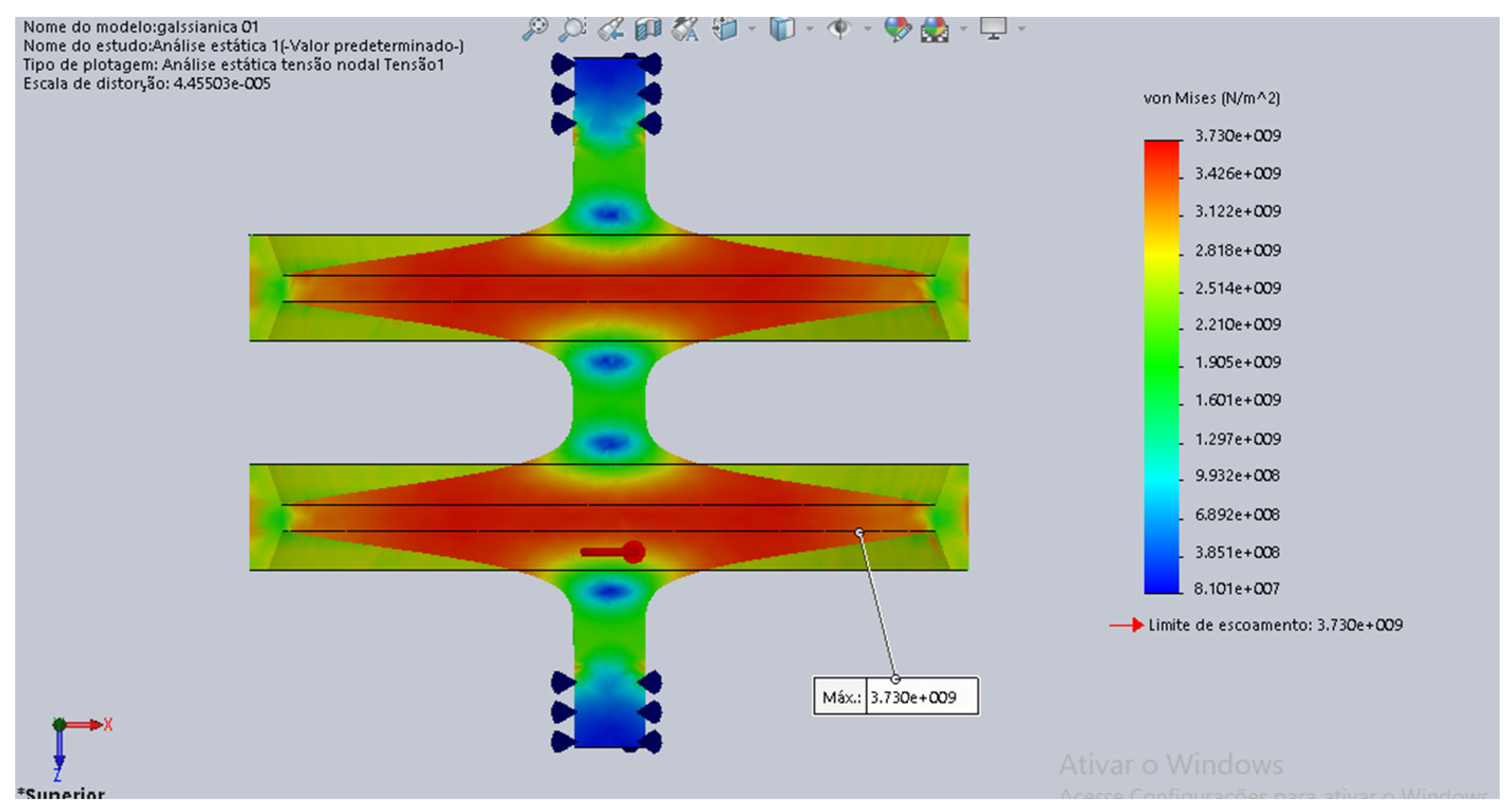
Figure 5 a flywheel is shown with a double Gaussian rotor and in
Figure 6 there is an example of a flywheel with a triple gaussian rotor. In
Table 5 there is an example of total energy, total mass, maximum rotation and energy density for a triple gaussian rotor.
3.4. Vibrational Modes for Stability
One of the main concerns when working at very high rotational speeds is the stability of the rotor. As the rotor spins, small variations in its shape create torques that could excite the rotor normal modes of vibration that, under resonance, could destroy the rotor and the flywheel.
In order to avoid such a situation, the vibrational normal modes of the flywheels were simulated to have their frequencies found. An example is shown in
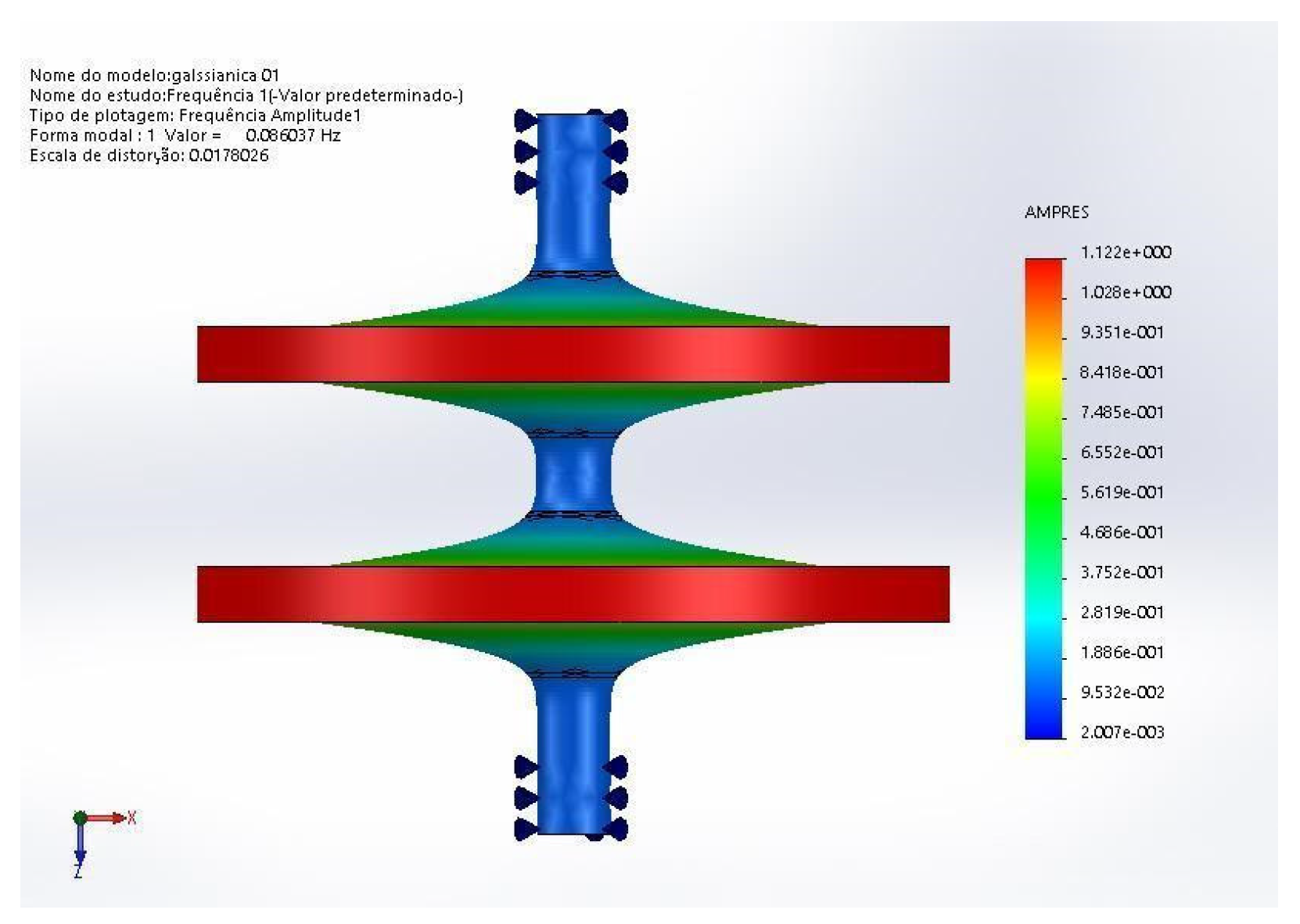
Figure 7,whose first normal mode has a frequency of 0.086 Hz and is characterised by the masses added to the edges of the Gaussian rotor vibrating up and down in the system’s axial direction. This mode is very inconvenient, as all the harmonics of this frequency could resonate with the rotation torque. These masses at the edges do not help much in increasing the energy density, so the best option seems to be to withdraw them from the flywheel. Therefore, all flywheel rotors now are formed only by the Gaussian-shaped ring. A double rotor vibration mode can be seen in
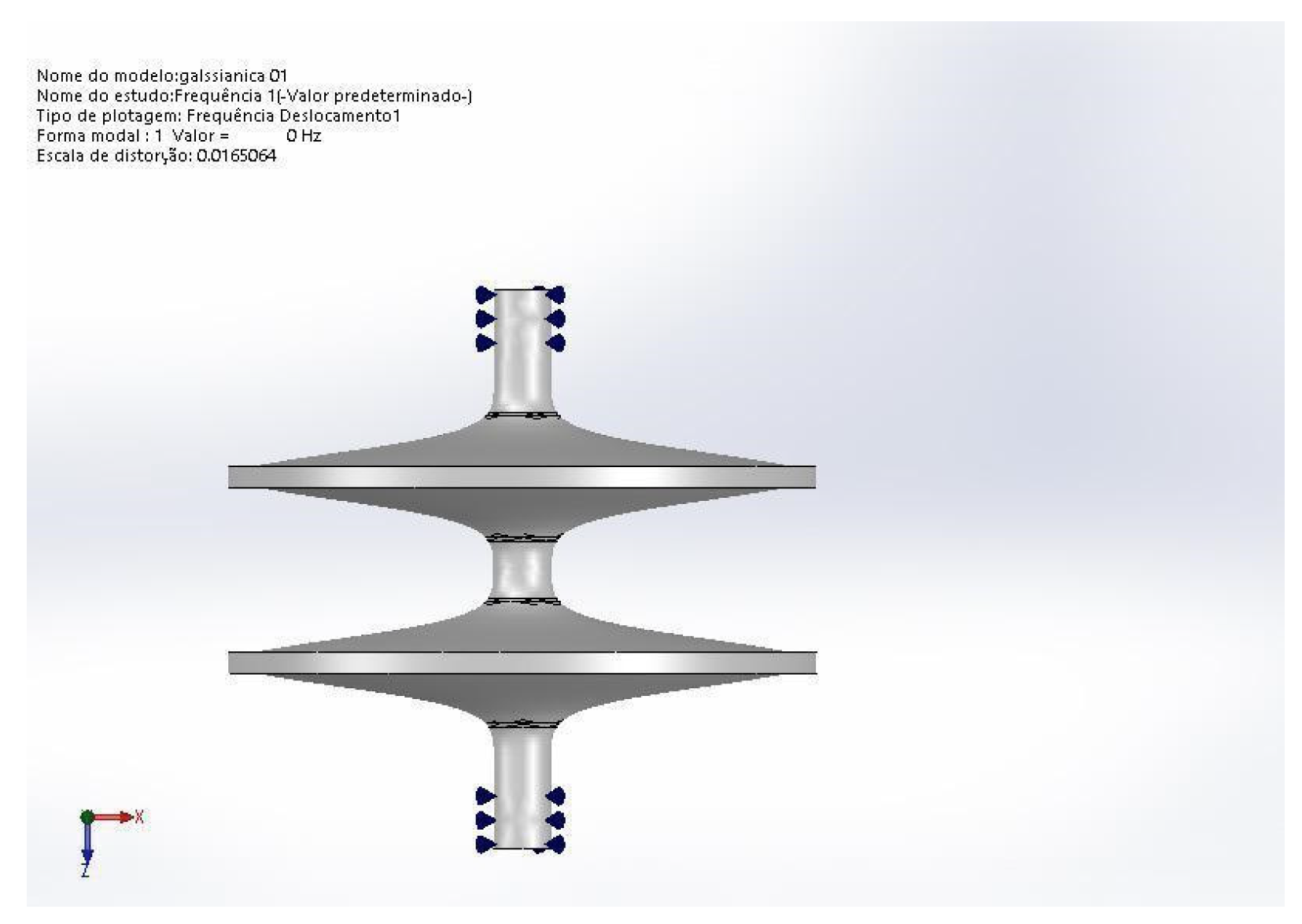
Figure 8 with only Gaussian disks and showing no signal of vibration as this model presents a frequency of zero for this mode with no amplitude of vibration.
The normal modes were then found with the simulations for the double and triple flywheel rotors. The respective frequencies and their harmonics could be avoided by the flywheel control system of the electromechanical battery; this job is reasonable as there are few of these modes in the flywheel operational range,
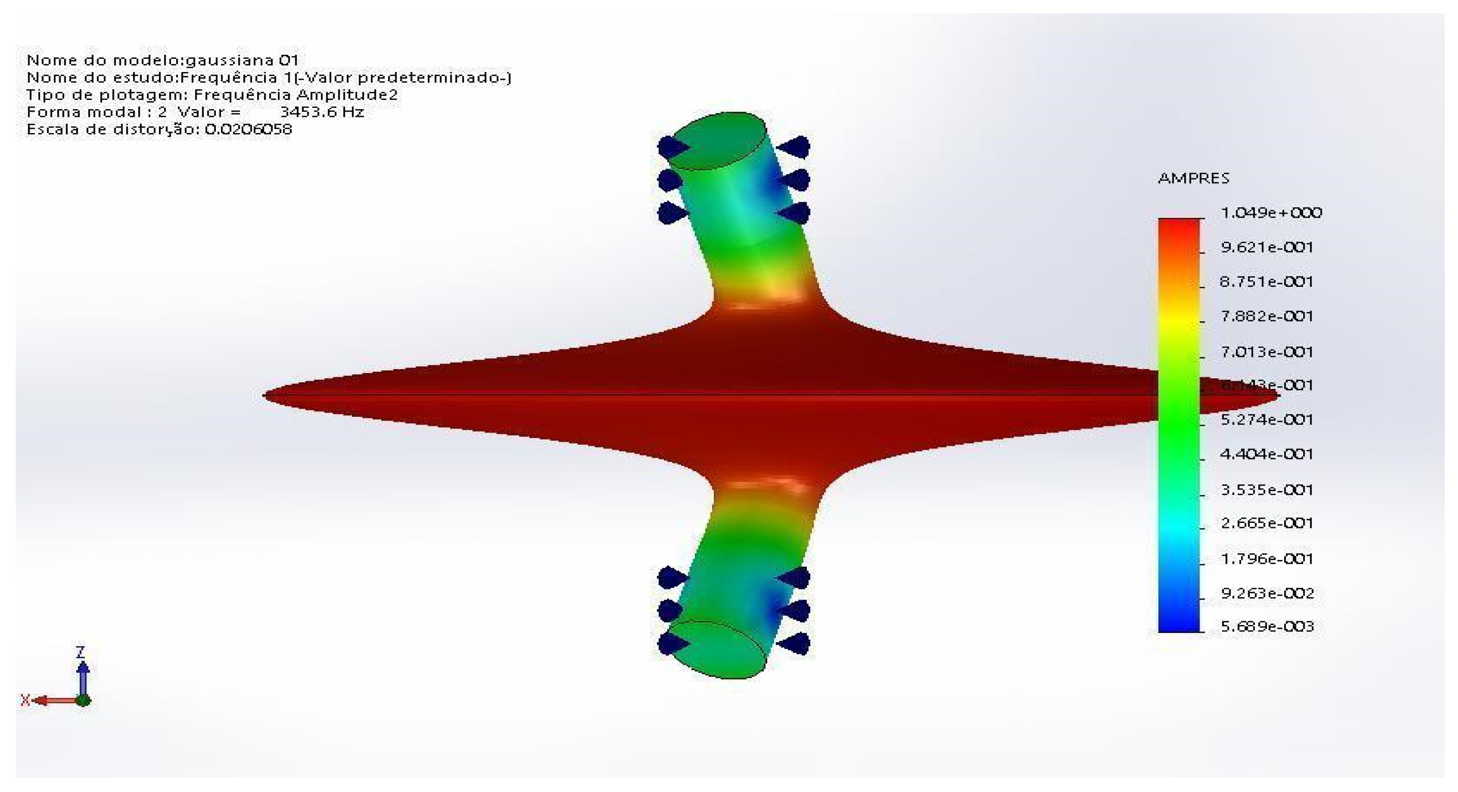
Figure 9 and
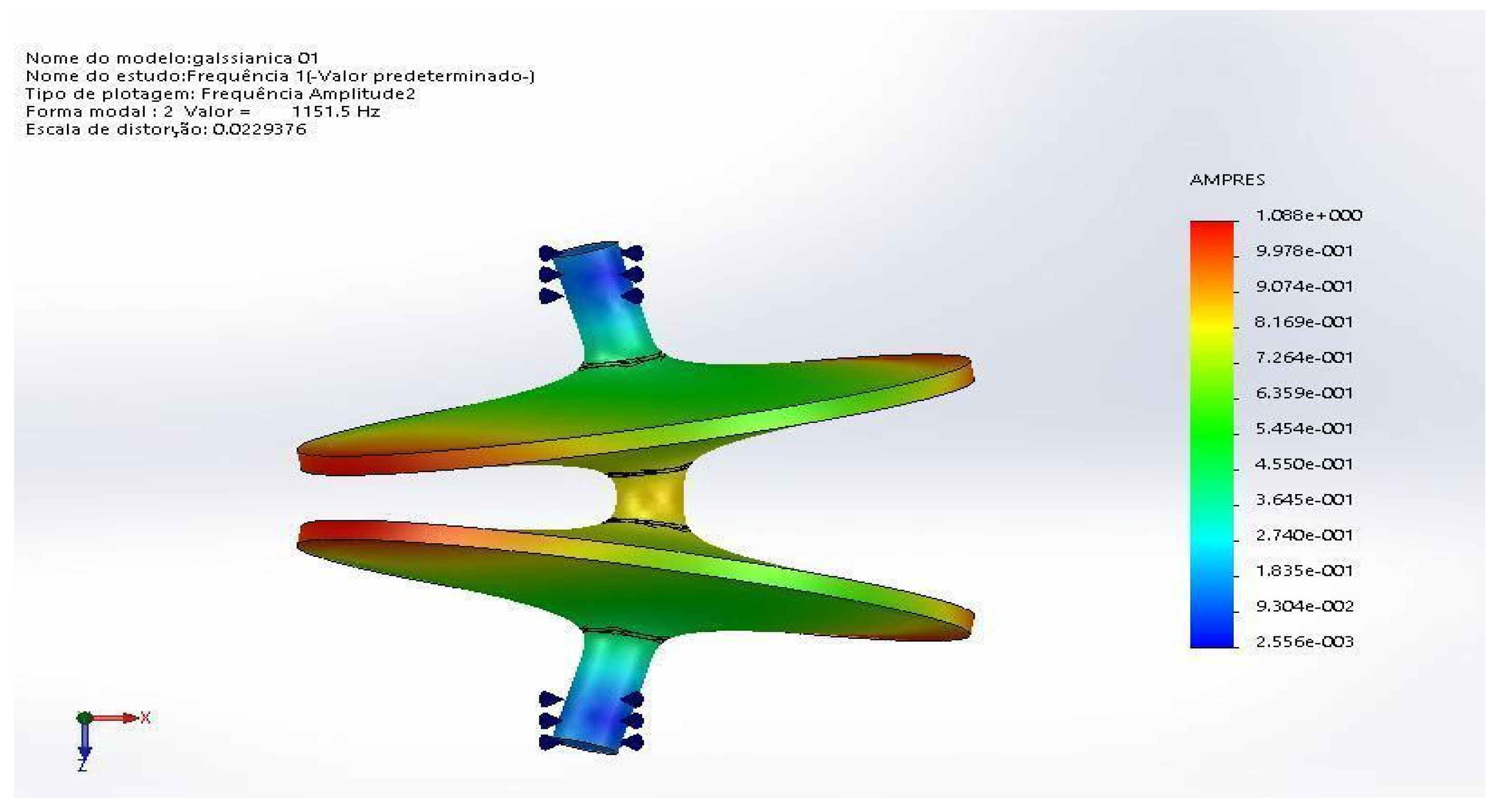
Figure 10 show these results. For the double rotor the first normal mode appears at a frequency of 1151 Hz, for a single rotor this frequency appears at 3341 Hz, these are the normal modes that appear in the operational range up to 4000 Hz in both cases.
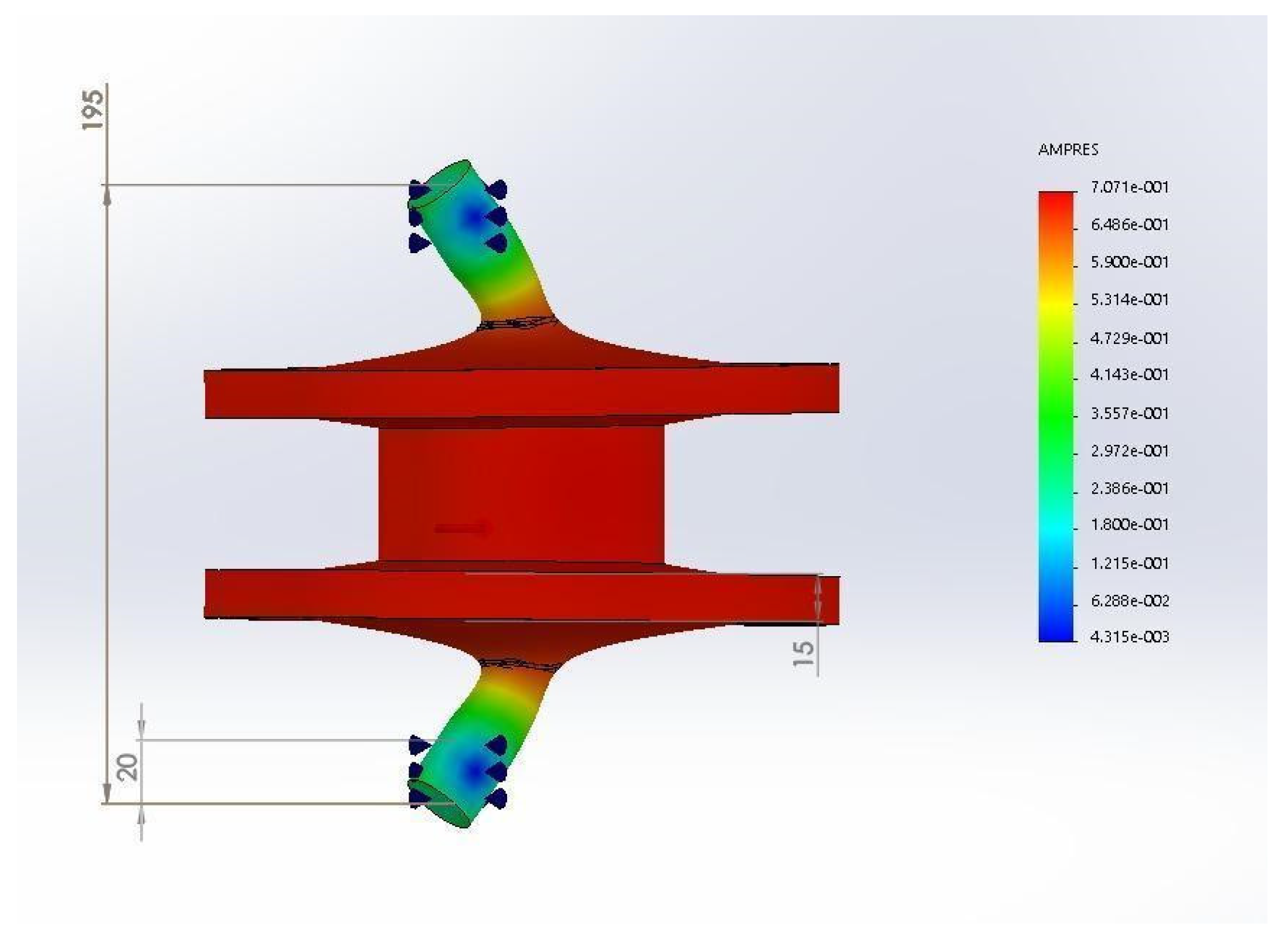
In order to avoid the instability of the double rotor flywheel a reinforcement was added connecting both disks, as shown in
Figure 11. The frequency of the first normal mode first was calculated as 2500 Hz. It can be changed to a higher value by making the bearing axes shorter. This was not done in the simulation as this length is necessary for the simulation to run. There is also the possibility of improvement making the reinforcement wider.
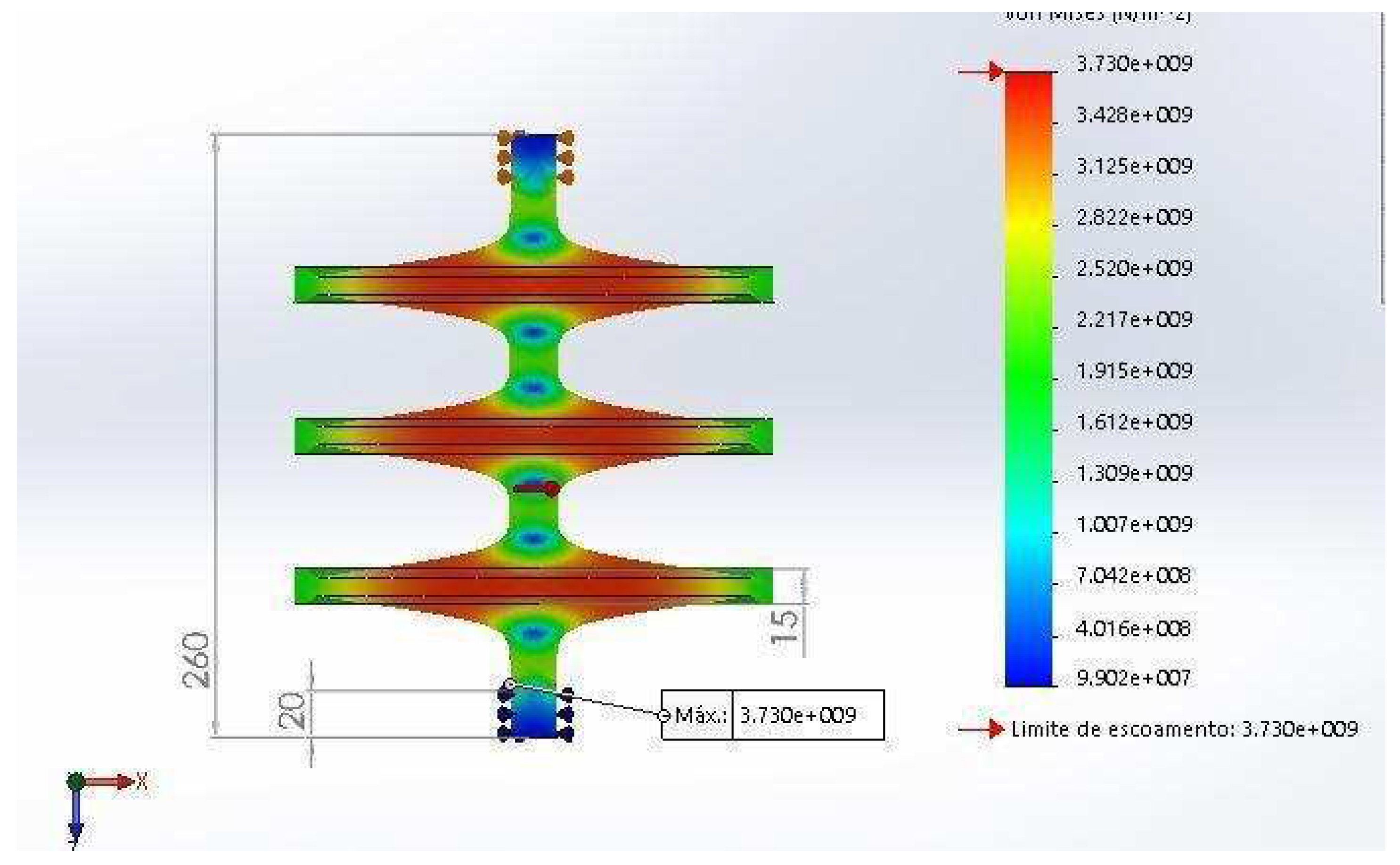
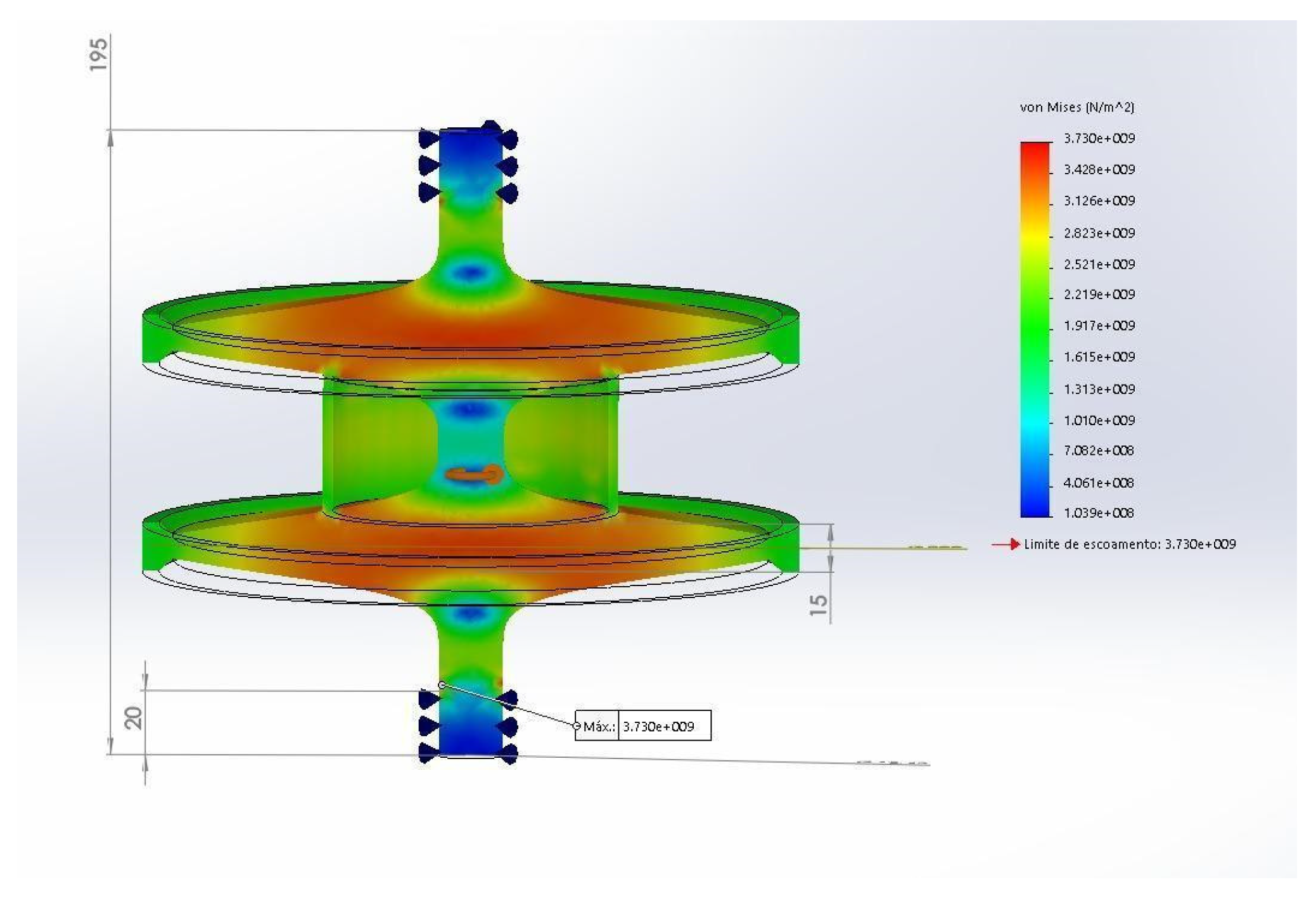
Figure 12 shows the simulation of this reinforced double rotor and presents an energy density of 403 Wh/kg or 1.45 MJ/kg, with some room for improvements as the point of maximum von Mises stress stress is located on the surface of the gaussian curve of the shaft.
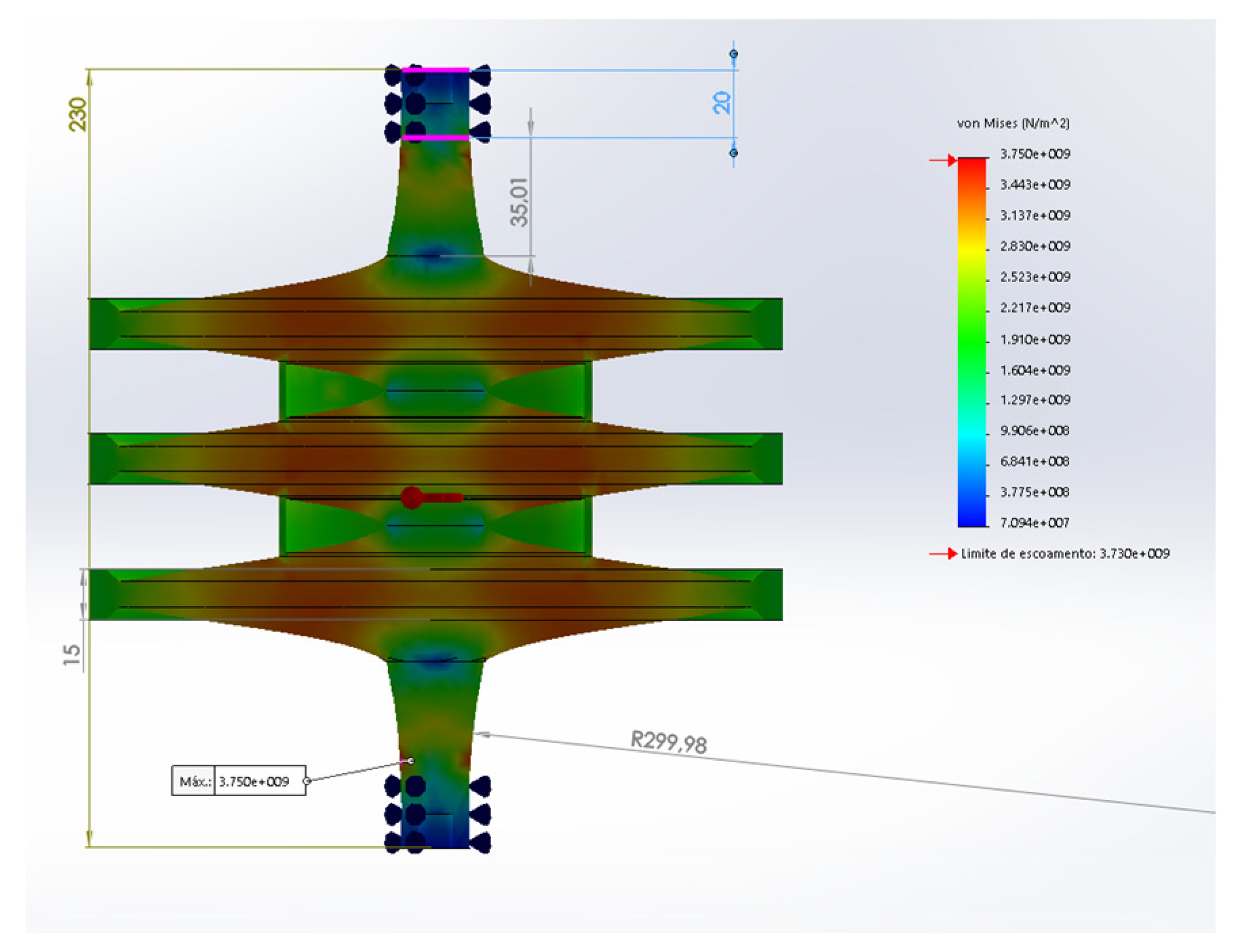
Figure 13 shows the same simulation for the reinforced triple rotor, which presents the same energy density of 403 Wh/kg or 1.45 MJ/kg, with some room for improvements as the point of maximum von Mises stress is located on the surface of the support axis.
4. Discussion
This work shows a case study of many flywheel rotors’ geometries by the use of FEM simulations. All flywheel rotors were assumed to be made of carbon fibre Hexcel UHM 12000. Eighteen different geometries were analysed, comparing: maximum rotational speed, total stored energy, total mass and specific stored energy. An analysis of the von Mises stress was made in all models, showing the critical stress points.
In regard to the total stored rotational energy, Model L presented the highest value of 2328 Wh. However, as it has a relatively large mass of 10.731 kg the respective energy density is only 216.97 Wh/kg, which is lower than most of the other models.
The model R, with the Gaussian-shaped rotor, presents the highest value for the specific energy, with a value of 387 Wh/kg, and the largest rotational speed of 279180 rpm.
As for the triple rotor, it reached an energy density of 431 Wh/kg, which is about 56% higher than the one found using eqn. (1) for the same Hexcel UHM 12000 carbon fibre (277 Wh/kg). There are more resistant carbon fibres available in the market, but this work kept it constant to allow for comparisons.
There is more room for improvement, but not much as almost all the volume of the flywheel is filled with high von Mises stress.
Possible instabilities due to normal rotational modes were found at the operational frequency, being one mode for each kind of flywheel rotor. These frequencies must be avoided at all costs in the flywheel’s operation, a process that can be easily implemented by a flywheel control system that can accelerate or decelerate the device as passing by these frequencies redirecting energy from one device to another as these devices operate in pairs.
The double and triple rotors can have their instability issues reduced by the use of a reinforcement tube connecting the two Gaussian disks that does not degrade the specific rotational energy much. As an example, we found that the reinforced double rotor has an energy density of 403 Wh/kg, also allowing room for improvement. This improvement will reach a maximum of 100%, where all the volume of the Flywheel has the maximum stress allowed in the material.
The results of this work are references for future investigations on the next steps for manufacturing an actual flywheel especially if they are made of carbon nanotubes, which are very expensive materials. If materials has enough resistance the storage density energy can reach the same values of common liquid fuels.
In the case carbon nanotubes can not be used because they could not be fabricated in long enough dimensions, the natural way is to use carbon fibres, as their resistance is improving with time.
The next step of this work is to simulate the resistance of these Flywheel rotors made of laminated carbon fibres aligned in the radial direction, the direction were the efforts are higher.
Author Contributions
Conceptualization: Carlso Frajuca; methodology: Carlos Frajuca and Fabio da Silva Bortoli; software: Daniel Coppede; validation: Carlos Frajuca and Daniel Coppede; formal analysis: all the authors; investigation: all the authors.; resources: Daniel Coppede; writing—original draft preparation: Carlos Frajuca and Nadja Simao Magalhaes; writing—review and editing: Nadja Simao Magalhaes; supervision: Carlos Frajuca and Fabio da Silva Bortoli; project administration: Carlos Frajuca and Joao Manoel Lozada Moreira; funding acquisition, Carlos Frajuca, Fabio da Silva Bortoli and Daniel Coppede
Funding
This research was funded by FAPESP through grant #2013/26258-4 and by CNPq through grant #312454/2021-0. The APC was funded by vouchers.
Conflicts of Interest
The authors declare no conflict of interest.
References
- Junling, C.; Xinjian, J.; Dongqi, Z.; Haigang, W. A Novel Uninterruptible Power Supply using Flywheel Energy Storage Unit. In Proceedings of The 4th International Power Electronics and Motion Control Conference - IPEMC 3, 2004, pp. 1180.
- Stephan, R.M.; Andrade, Jr.R.; Sotelo, G.G. Third Generation of Flywheels: a Promising Substitute to Batteries. Revista Eletronica de Potencia 2008, 13, pp. 171. [CrossRef]
- Fiske, O.J.; Ricci, M.R. Third Generation Flywheels For High Power Electricity Storage. LaunchPoint Technologies, Inc., 2016 Goleta, California, USA. Available online: https://www.launchpnt.com/hs-fs/hub/53140/file-14467597-pdf/docs/002_fiske_powerring.pdf.
- Bankston, S.; Mo, C. Geometry Modification of Flywheels and its Effect on Energy Storage. Energy Res. J. 2015, 6, 54. [CrossRef]
- IRENA. International Renewable Energy Agency. Electricity Storage and Renewables: Costs and Markets to 2030. International Renewable Energy Agency, 2017 Abu Dhabi.
- Ribeiro, M.R. Sistema Armazenador de Energia Cinetica SAEC - Estrategia de Controle e Simulacoes. Rio de Janeiro: MSc thesis - COPPE/UFRJ, Brazil, 2008.
- Hedlund, M.; Lundin, J.; de Santiago, J.; Abrahamsson, J.; Bernhoff, H. Flywheel Energy Storage for Automotive Applications. Energies 2015, 8, 10636. [CrossRef]
- Ashby, M.F. 2017 Materials Selection in Mechanical Design. Fifth edition, Elsevier Ltd., Cambridge, United States.
- Wang, B. CNT bundle material for flywheels: 40 times better than batteries. 2018. Available https://www.nextbigfuture.com/2018/10/cnt-bundle-material-for-flywheels-40-times-better-thanbatteries.html.
- MatWeb - The Online Materials Information Resource. Available online: http://www.matweb.com.
- Coppede, D. Análise por Simulação de Materiais Conjugados para Baterias Eletromecânicas. MSc thesis - IFSP, Sao Paulo, Brazil, 2018.
- Bortoli, F.S.; Frajuca, C.; Sousa, S.T.; de Waard, A.; Magalhaes, N.S.; Aguiar, O.D. On the massive antenna suspension system in the brazilian gravitational wave detector Schenberg. Braz. J. Phys. 2016, 46, 308. [CrossRef]
- Andrade, L.; Costa, C. Aguiar, O.D.; Frajuca, C.; Mosso, M.; Podcameni, A.; Da Silva, H.; Magalhaes, N.S. Ultra-low phase noise 10 Ghz oscillator to pump the parametric transducers of the mario Schenberg gravitational wave detector. Class Quantum Gravity 2004, 21, S1215. [CrossRef]
- Bortoli, F.S.; Frajuca, C.; Magalhaes, N.S.; Duarte, E.N. A physical criterion for validating the method used to design mechanical impedance matchers for mario schenberg’s transducers. J. Phys. Conf. Ser. 2010, 228, 012001. [CrossRef]
- SOLIDWORKS. Available online: https://www.solidworks.com.
- Nogueira, P.R.M. Otimizacao de Geometria e Material para Baterias Eletromecanicas. MSc thesis - IFSP, Sao Paulo, Brazil, 2016.
- Aguiar, O.D.; et al. The gravitational wave detector “Mario Schenberg”: Status of the project. Braz. J. Phys. 2002, 32, 866. [CrossRef]
- Frajuca, C.; Bortoli, F.S.; Magalhaes, N.S. Resonant transducers for spherical gravitational wave detectors. Braz. J. Phys. 2005, 35, 1201. [CrossRef]
- Frajuca, C.; Bortoli, F.S.; Magalhaes, N.S. Studying a new shape for mechanical impedance matchers in Mario Schenberg transducers. 2006 J. Phys. Conf. Ser. 2006, 32, 319. [CrossRef]
- Frajuca, C.; Souza, M.A.; Coppede, D.; Nogueira, P.R.M.; Bortoli, F.S.; Santos, G.A.; Nakamoto, F.Y. J. Braz. Soc. Mech. Sci. Eng. 2018, 40, 319. [CrossRef]
- Bortoli, F.S.; Frajuca, C.; Magalhaes, N.S.; Aguiar, O.D.; Souza, S.T. On the cabling seismic isolation for the microwave transducers of the Schenberg detector. 2019 Braz. J. Phys. 2019, 49, 133. [CrossRef]
- Kress, R. Shape optimization of a flywheel. Struc. Multidiscipl Optim 2000, 19, 74. [CrossRef]
|
Disclaimer/Publisher’s Note: The statements, opinions and data contained in all publications are solely those of the individual author(s) and contributor(s) and not of MDPI and/or the editor(s). MDPI and/or the editor(s) disclaim responsibility for any injury to people or property resulting from any ideas, methods, instructions or products referred to in the content. |
© 2023 by the authors. Licensee MDPI, Basel, Switzerland. This article is an open access article distributed under the terms and conditions of the Creative Commons Attribution (CC BY) license (http://creativecommons.org/licenses/by/4.0/).
