
You are currently viewing a beta version of our website. If you spot anything unusual, kindly let us know.
Preprint
Article
Numerical Investigation for Strengthening a Concrete Filled Steel Tube Composite Columns Using CFRP
Altmetrics
Downloads
85
Views
28
Comments
0
A peer-reviewed article of this preprint also exists.


This version is not peer-reviewed
Abstract
Hollow and concrete-filled steel tubes (CFSTs) are widely used as columns in many structural systems and local buckling can occur when they are subjected to axial compression loading. The critical regions for the local buckling of the columns are near the ends of the column where the moments are the highest. To strengthen the critical regions of the CFSTs the CFRP provides a simple and effective method which used previously as an enhancement for both of strength and ductility. So, this study suggests investigating the axial load behaviour of CFST strengthened with CFRP using FE method after a verification study and then a various parametric studies were carried out to cover the effect of the CFRP layers, number, confinement length and position. The FE results proved that, one CFRP sheet with thickness equal to 1.2 mm was strengthened the composite column by 8.5%, two CFRP sheets with total thickness equal to 2.4 mm was strengthened the composite column by 23.5%, three CFRP sheets with total thickness equal to 3.6 mm was strengthened the composite column by 35.1% and four CFRP sheets with total thickness equal to 4.8 mm was strengthened the composite column by 44.5%. Moreover, this study proved that by strengthened the composite columns with CFRP sheets with different lengths, the axial load resistance was improved by 8.5%, 4.6%, 0.1% and 0.0% for length percentages 100%, 75%, 50% and 25% respectively.
Keywords:
Subject: Engineering - Civil Engineering
1. Introduction
Hollow and concrete-filled steel tubes find widespread application as columns in various structural systems (Al Zand, Badaruzzaman et al. 2015, Contento, Aloisio et al. 2022, Liao, Zeng et al. 2022). These columns can experience local buckling when subjected to axial compression alone or combined with monotonic/cyclic loading (Hilo, Sabih et al. 2022). While buckling modes are crucial failure considerations for concrete-filled steel tubes (CFST) under axial compression and/or bending, similar failure tendencies are observed in thinner cylindrical shells of steel storage silos and tanks. These buckling issues manifest under combined axial compression and internal pressure, both in cyclic and static loading scenarios (Hilo, Sabih et al. 2021, Abdulrazzaq, Hilo et al. 2022, Al Zand, Badaruzzaman et al. 2016). The synergy between concrete and steel in CFST offers benefits: the steel tube confines the concrete and vice versa, effectively delaying local buckling. Primarily employed as columns in buildings and bridges, CFSTs represent economical structural elements, supported by extensive research in the field (Uy 1998, Haj-Ali and Kilic 2002, Han, Tao et al. 2004).
Fiber reinforced polymer (FRP) composites are crafted by embedding continuous fibers within a polymer resin matrix (Al-Zand, Badaruzzaman et al. 2017). Two prevalent FRP systems are recognized: the glass FRP (GFRP) system and the carbon FRP (CFRP) system (Belarbi and Acun 2013). FRP composites boast a high strength-to-weight ratio, exceptional corrosion resistance, and facile on-site handling due to their lightweight nature and adhesive bonding technique (Van Den Einde, Zhao et al. 2003, EL-Fiky, Awad et al. 2022, Kumar, Rangappa et al. 2022). These advantageous characteristics have propelled the adoption of FRP composites in civil engineering. A variety of commercial FRP products, such as bars, sheets, plates, and profiles, have emerged, serving diverse construction purposes: new builds, structural reinforcement/repair, internal reinforcement, and external strengthening. Notably, the external application of FRP composites for strengthening/repairing composite column structures has gained popularity (Ye, Zeng et al. 2022). A novel column design introduced by (Xiao, He et al. 2005) entails confined CFT (CCFT) columns, featuring steel tube segments or FRP jackets at the column's end portions. This approach prevents inward deformation by the concrete core and outward deformation by the jacket, markedly enhancing both ductility and strength in the column's end regions. (Xiao and Wu 2000) validated several anticipated benefits of the CCFT system through initial tests. It's noteworthy that the CCFT system and the tube confinement retrofit method proposed by (Al-Rousan 2022) share a common principle. The use of FRP jackets to mitigate local buckling in circular hollow steel tubes and shells was initially explored at The Hong Kong Polytechnic University, building upon (Wright 1993) concept for FRP confinement of CFT columns.
The literature discussed above clearly demonstrates the potential of CFRP in reinforcing CFSTs. Strengthening CFST using CFRP presents a globally employed method to significantly enhance both strength and ductility. Similar to other structural elements, CFST columns might require upgrading or reinforcement for reasons such as accommodating additional loads or recovering from external damage. In this context, the utilization of CFRP composite sheets has emerged as a highly suitable strategy for reinforcing composite elements in recent times (Ye, Liang et al. 2021). These sheets are user-friendly, exceptionally flexible (moldable into various shapes) (Abdulrazzaq, Hilo et al. 2022), exhibit a higher modulus of elasticity, and possess greater tensile strength compared to steel (Pawlak, Górny et al. 2022).
However, enveloping CFST composite columns with varying lengths and quantities of unidirectional CFRP sheets may not prove to be an economical solution. Additionally, applying CFRP sheets over short spans of CFST composite columns' length could result in failure due to debonding. This is attributed to the substantial peeling stress that arises along the bond interface between the steel and CFRP sheets, particularly under considerable bending stress. Given this context, this study proposes an examination of the axial load behavior of CFRP-strengthened CFST under diverse parametric scenarios. This investigation aims to encompass the impact of factors like the number of CFRP layers, confinement length, and positioning, thereby providing a comprehensive understanding.
2. Experimental Study
The methodology of this research was described in three different stages: the first stage was, compare the results of the FE analysis using ABAQUS software (Hibbitt, Karlsson et al. 2011) with results of an existing experimental test done by (Han and Yao 2004). Second stage was, generate a parametric study to cover the effect of the CFRP layers, length and positions on the axial load behaviour of the CFST composite columns strengthened with CFRP by designing many different FE models. Third stage was, generate the FE analysis results, conclusions and suggestions.
An existing experimental study done by (Han and Yao 2004) was chosen for the verification in this study. Thirty-eight specimens, including 18 stub columns and 20 beam columns were tested. The main parameters varied in the tests are: (1) column section type, circular and square; (2) tube diameter (or width) to thickness ratio, from 33 to 67; and (3) load eccentricity ratio (e/r), from 0 to 0.3 mm.
Among all of the experimental models (38 models), this study suggests to choose specimen 1 which labelled as (ICSCI-1) in the existing study. This study selects the specimen 1 as an experimental test to verify the FE analysis only, so it was suggested to avoid the other specimens which were designed with different details and not valid for the main objective of this research. Brief details of the experimental specimen were presented in Table 1 and the cross-section was presented in Figure 1.
3. Finite Element Modelling
Nonlinear full scale FE models were prepared, designed and analyzed using ABAQUS software (Hibbitt, Karlsson et al. 2011) in order to investigate the structural behaviour of CFST composite columns strengthened with CFRP sheets. Boundary conditions, elements types, parts, meshing, and material modelling, of the FE models were presented in details in this study.
3.1. Geometry, element assignment and interaction
The primary Finite Element (FE) model was crafted using ABAQUS software (Hibbitt, Karlsson et al. 2011), adhering to the specifications of the experimental test, including loading system, test arrangement, and boundary conditions. This model aimed to simulate CFST composite columns reinforced with CFRP sheets. Notably, the FE simulation employed a comprehensive scale model (depicted in Figure 2) for all CFST composite columns.
In this investigation, a progressive monotonic analysis was conducted using the displacement load approach. Loading was incrementally applied to specific points, increasing at a controlled rate of 0.1 mm/s. This process continued until the ultimate capacity of the CFRP-strengthened CFST composite columns was attained. The loading system employed in Abaqus supported this procedure.
Within the ABAQUS software, an array of element types is available in the Standard Element Library. For this study, the choice was made to utilize the S4R element type for the steel tube and CFRP components. In parallel, the element type C3D8R was chosen to represent the concrete material. For a more comprehensive breakdown of element selections for each segment of the FE model, refer to Table 2.
Ensuring alignment between the outcomes of the experimental test and the FE model necessitates meticulous consideration of surface interactions among the constituent parts of the composite columns, including concrete, steel tube, CFRP, and adhesive substances. This stands out as a pivotal and intricate aspect of parameter selection.
Therefore, this study adopts the ‘cohesive behaviour’ technique which it is breakable nodes along the surface interaction between the steel tube and the CFRP. The full tie interaction technique was selected to represent the surface interaction between the inner surface of the steel tube and the outer surface of concrete, because no slip is assumed to occur along the surface interaction due to bending; the reason was the tube totally confines the concrete core at all of the loading stages. For more details Table 3 presented summery of the interaction type between the parts of the composite column FE model.
3.2. Properties of Materials
This section outlines the material properties utilized in the study, offering a comprehensive insight into their integration within the FE models.
- Steel
The material properties of steel adopted in the FE models precisely mirrored those from the experimental parameters. These properties encompass Poisson's ratio, modulus of elasticity, and yield strength, with values directly sourced from the pre-existing experimental study. Specifically, these values were 0.3, 206,500 MPa, and 303.5 MPa, respectively, as detailed in Table 4. Notably, the steel material is characterized as an elastic-plastic isotropic substance. Implementing these mechanical attributes in the FE models using Abaqus involved opting for the elastic-isotropic approach to define mechanical properties. The tri-linear stress-strain model exhibited in Figure 4, as presented by (Han and Yao 2004), was embraced in this study to estimate stress-strain correlations within the FE models.
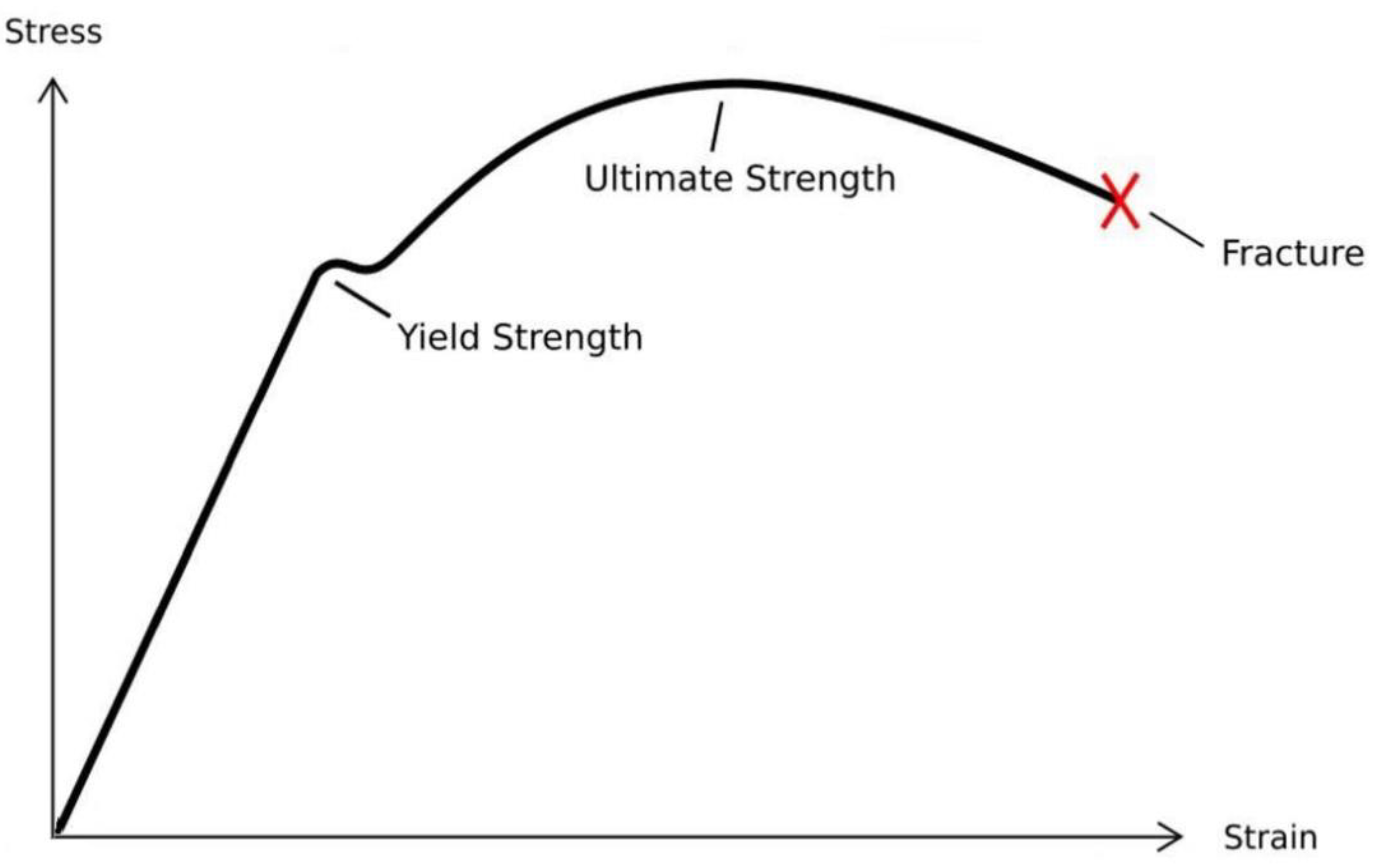
Figure 4.
Stress-strain curve of steel material used in the FE model. Source: (Han and Yao 2004).
- Concrete
The concrete properties adopted in this study were directly extracted from the experimental tests. Compressive strength was assigned a value of 40 MPa, Poisson's ratio 0.2, and the modulus of elasticity 37,420 MPa, as outlined in Table 5. Concrete, in its essence, is an isotropic substance. To represent its mechanical elasticity in the FE models through Abaqus, the elastic-isotropic approach was employed to define the modulus of elasticity and Poisson's ratio. Additionally, the mechanical-plasticity properties were identified through the selection of the concrete damaged plasticity option. Figure 5 depicts the stress-strain relationship for concrete, adopting the same equations as (Sundarraja and Prabhu 2011).
- CFRP sheet
For enhancing CFST columns, unidirectional CFRP sheets were introduced. Specifically, the MBrace 240 type of CFRP sheet was utilized, characterized by a modulus of elasticity of 240,000 GPa, ultimate tensile strength of 1747 MPa, sheet thickness of 1.2 mm, and Poisson's ratio of 0.4, as provided in Table 6. Notably, CFRP material follows an elastic-brittle nature. Thus, its mechanical properties are represented through the fiber reinforced polymer-Hashin Damage model (Al-Zand, Badaruzzaman et al. 2017). This material is treated as orthotropic, and its elastic-engineering constants are harnessed to determine key elasticity properties, including the modulus of elasticity, Poisson's ratio, and shear modulus.
4. Convergence Study
Convergence study was generated in this study to find the suitable meshing for the FE modelling in non-linear analysis for the CFST composite columns. To verify the finer meshing for the models, six different meshes sizes were applied and analyzed, the meshing sizes were 30, 40, 50, 60, 70 and 80 mm as presented in Figure 6. These meshing sizes were with different ultimate axial loading. This study found that the axial loading resistance between the model with 60 mm meshing size and 70 mm meshing size had no considerable difference through comparing the ultimate axial load for each mesh size, as presented in Figure 7. The ultimate axial loads for the FE model with 50 mm meshing size was 2,161 kN and it was equal to 1841kN for the FE model with 60 mm meshing size which it was very near to the experimental ultimate axial loading 1818 kN. This study suggests choosing meshing size 60 mm as a meshing size for all of the rest of the composite columns FE models because of the high accuracy and less analysis time for the models.
5. Verification Study
An existing experimental study done by Han and Yao (2004) was chosen for the verification in the current study. This study suggests choosing specimen 1 which labelled as (ICSCI-1) in the existing study. Brief details of the existing experimental specimen were presented in Table 7.
A FE model was designed and analyzed with parameters exactly similar to the experimental test and results were compared. The experimental test was labelled as Lcsc11, and the FE model labelled as Cir-CM. The ultimate axial loading for the experimental test was 1818 kN with 5.5 mm displacement, and the ultimate axial loading for the FE model was 1841 kN with displacement 5.8 mm as presented in Table 8.
The accuracy of the FE verification was achieved through the comparison and the deviation percentage was 1.2 % only as presented in Figure 8 which it considered very close to the experimental results. The verified FE model (CM) was selected as a control model for all of the parametric study.
It was suggested in this study to investigate the effect of CFRP sheets on the square CFST composite column as well. Therefore, a FE model was analyzed and designed and the properties of the FE Model were exactly similar to the experimental test. The cross-section area for the Square CFST was 30,625 mm2 and it was similar to the Circular CFST cross-section area 31,415.9 mm2. Moreover, the moment of inertia for both of the cross-section was very close as well which it were around 78,157,552. As a result, Figure 9 presenting the axial load – displacement for the circular and square CFST to prove that these two different cross-sections were with very similar load displacement behaviour.
6. Parametric Studies
This study suggests investigating the effect of various parameters on the axial load behaviour of circular and square CFST composite columns strengthened with CFRP to present more information about using the CFRP as a strengthening method for the composite columns. The main parameters were the effect of CFRP layers numbers and positions and confinement length for both cross-sections circular and square.
6.1. Effect of CFRP layers numbers
It was suggested to investigate the effect of the CFRP layers numbers on the axial load behaviour of circular and square CFST composite columns to present clear understanding about the CFRP positive effect on the cross-section shape of the CFST composite column.
Eight (8) different FE models were designed and, analyzed and divided into two groups, the first group was four (4) FE models designed with circular cross-sectional shape, the first FE model was with 1 CFRP layer and labelled as Cir-1.2, second FE model was with 2 CFRP layers and labelled as Cir-2.4, third FE model was with 3 CFRP layers and labelled as Cir-3.6 and the fourth FE model was with 4 CFRP layers and labelled as Cir-4.8. The second group, was another four (4) FE models but this time the models designed with square cross-sectional shape, the first FE model was with 1 CFRP layer and labelled as Squ-1.2, second FE model was with 2 CFRP layers and labelled as Squ-2.4, third FE model was with 3 CFRP layers and labelled as Squ-3.6, and the fourth FE model was with 4 CFRP layers and labelled as Squ-4.8. Figure 10 (a and b) presenting the cross-sectional shapes of the FE CFST composite columns models with different CFRP layers number.
To assess the influence of CFRP sheet quantity on the axial load behavior of CFST composite columns, the ultimate axial load of the initial group of FE models (with circular cross-sectional shape) was juxtaposed with the ultimate axial load of the control model (Cir-CM). The ultimate axial load values were as follows: 1998 kN, 2275 kN, 2488 kN, and 2660 kN for FE models Cir-1.2, Cir-2.4, Cir-3.6, and Cir-4.8, respectively. These results are tabulated in Table 9, and the corresponding displacement was approximately 5.6 mm.
The FE results proved that, number of CFRP sheet was positively affect on the axial load behaviour of the CFST composite column with circular cross-sectional shape. One CFRP sheet with thickness equal to 1.2 mm was strengthened the composite column by 8.5%, two CFRP sheets with total thickness equal to 2.4 mm was strengthened the composite column by 23.5%, three CFRP sheets with total thickness equal to 3.6 mm was strengthened the composite column by 35.1% and four CFRP sheets with total thickness equal to 4.8 mm was strengthened the composite column by 44.5% as presented in Figure 11.
To evaluate the impact of varying CFRP sheet quantities on the axial load behavior of CFST composite columns, the ultimate axial load of FE models featuring square cross-sectional shapes was juxtaposed with that of the control model (Squ). The ultimate axial load values stood at 1979 kN, 2112 kN, 2235 kN, and 2713 kN for FE models Squ-1.2, Squ-2.4, Squ-3.6, and Squ-4.8, respectively. These findings, detailed in Table 10, exhibited a consistent displacement of around 7.5 mm across all FE models.
The FE results proved that, number of CFRP sheet was positively affect on the axial load behaviour of the CFST composite column with square cross-sectional shape. One CFRP sheet with thickness equal to 1.2 mm was strengthened the composite column by 5.1%, two CFRP sheets with total thickness equal to 2.4 mm was strengthened the composite column by 12.1%, three CFRP sheets with total thickness equal to 3.6 mm was strengthened the composite column by 18.6% and four CFRP sheets with total thickness equal to 4.8 mm was strengthened the composite column by 44.0% as presented in Figure 12.
The stress of the FE CFST models strengthened with different CFRP sheets was presented in Figure 12. The failure mode for the FE models was local at the ends of the CFST composite columns and the stress was uniformly distributed on the CFRP sheets, meanwhile the highest stress for the control models (no CFRP) was local buckling at the bottom end of the CFST composite columns and that lead to concrete crash and steel tube local buckling at the same position. This parametric proved that the CFRP sheets decrease the local buckling and enhanced the concrete compression resistance and increase the ultimate axial loading as presented in Figure 12.
6.2. Effect of CFRP Confinement Length
The confinement effect of the CFRP sheets on the axial load behaviour of the CFST composite columns was studied as well and another eight (8) FE models were designed and analyzed and divided into two groups, the first group was with four FE models designed with circular cross-sectional shape, the first FE model was with 50% CFRP sheets confinement of the CFST composite columns total length and positioned in the mid span, second FE model was with 75% CFRP sheets confinement of the CFST composite columns total length and positioned in the mid span as well, third FE model was with 100% CFRP sheets confinement of the CFST composite columns total length positioned in mid span also and the fourth FE model was with two 25% CFRP sheets confinement of the CFST composite columns total length the first it was 25% in the top side and the second 25% in the bottom side as presented in Figure 13-(a). the second group was with different four FE models designed with square cross-sectional shape, and the CFRP sheets confinement of the CFST composite columns were designed exactly similar to the first group as presented in Figure 13-(b).
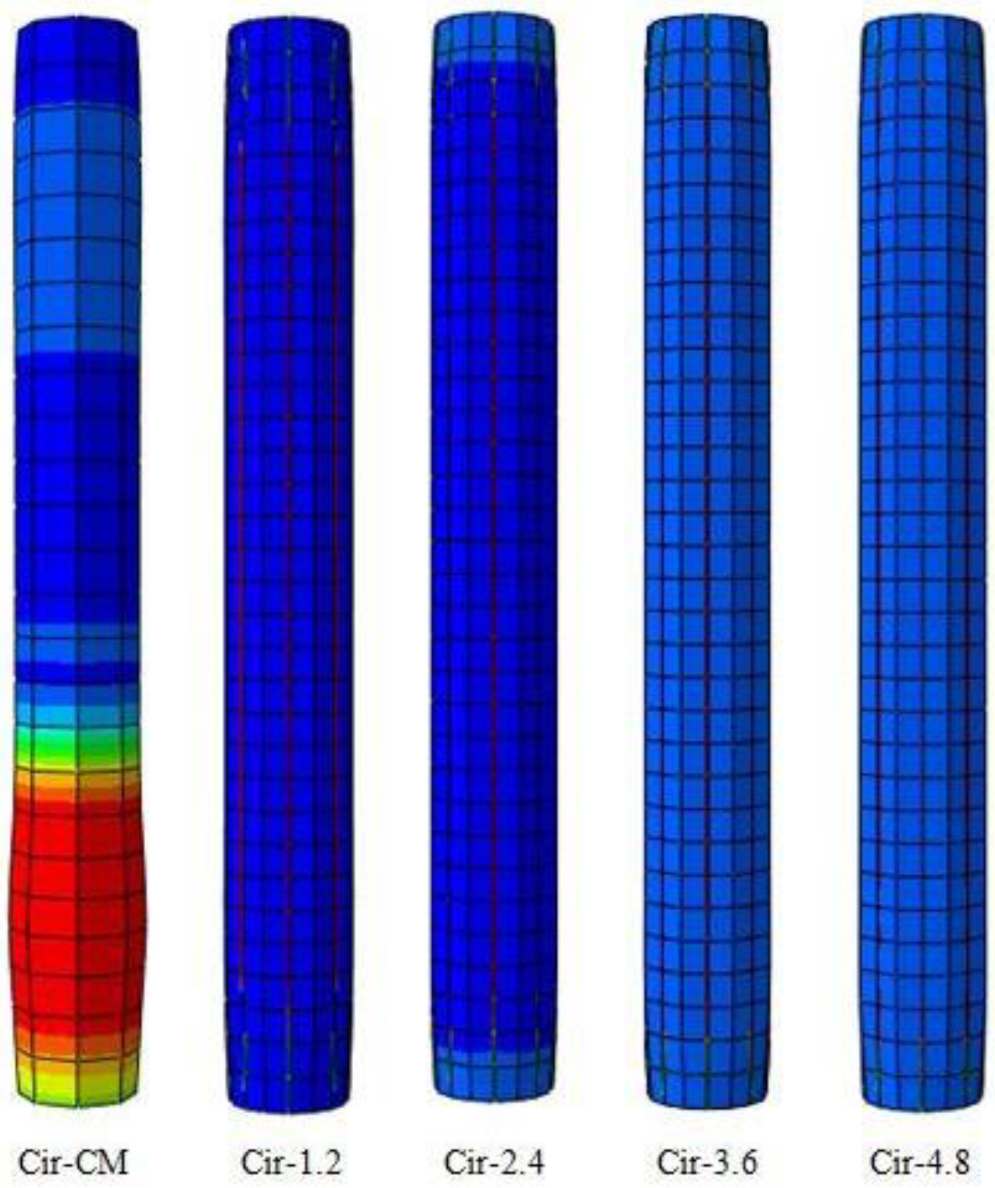
Figure 12.
Stress for the circular CFST strengthened with/without CFRP sheets with different layers.
Figure 12.
Stress for the circular CFST strengthened with/without CFRP sheets with different layers.
The results proved that the ultimate axial load for the FE models of the first group (circular cross-section) was equal to 1998, 1972, 1843 and 1842 kN, respectively for the models Cir100%, Cir-75%, Cir-50% and Cir-25% and it was with displacement 5.7 mm for all of these FE models as presented in Table 11. Improvement percentages were recorded for the FE models when strengthened with CFRP with different lengths ant it was equal to 8.5, 4.6, 1.1 and 1.01% respectively for the FE models Cir-100%, Cir-75%, Cir-50% and Cir-25% as presented in Figure 14.
The results proved that the ultimate axial load for the second group (square cross-sectional shape) of the FE models was equal to 1997, 1934, 1885 and 1884 kN, respectively for the FE models Sqe-100%, Sqe-75%, Sqe-50% and Sqe-25% and the with displacement was around 5.7 mm for all of these FE models as presented in Table 12. Improvement percentages were recorded for the FE models when strengthened with CFRP with different lengths and it was equal to 5.10, 2.63, 0.06 and 0.002%, respectively, for the FE models Sqe-100%, Sqe-75%, Sqe-50% and Sqe-25% as presented in Figure 15.
The stress of the FE square CFST composite columns strengthened with CFRP sheets with different lengths was presented in Figure 19. The failure mode for the FE models Sqe100%, Sqe-75%, Sqe-50% and Sqe-25% was local at the area which it was unconfined with CFRP meanwhile the failure mode for the control models Sqe-CM (no CFRP) was local buckling at the mid span. The FE results proved that the CFRP sheets decrease the local buckling and increases the ultimate axial loading.
7. Failure Mode and Discussion
In this section, the study delves into the failure mode predictions between the FE analysis and their comparison with the results of an existing experimental study conducted by Han and Yao (2004).
The primary objective of this study was to assess the accuracy of the FE analysis in predicting the failure modes of CFST composite columns strengthened with CFRP sheets. The verification process involved selecting a specific specimen, labeled as ICSCI-1 in the experimental study, to serve as the experimental benchmark for the FE analysis of the current study. In the verification phase, the study opted to use specimen ICSCI-1 from the existing experimental dataset, as it closely aligned with the objectives of our research. This specimen was subjected to various parameters, including column section type (circular), tube diameter to thickness ratio, and load eccentricity ratio. The decision to focus on specimen ICSCI-1 ensured the compatibility of the FE analysis with the experimental data.
The results of the FE analysis exhibited an exceptionally close alignment with the experimental findings, both in terms of ultimate axial load behavior and failure mode prediction. Figure 20 show cases a visual representation of this remarkable agreement between the FE analysis and the experimental test. The figure highlights the accuracy of the FE model in capturing the specific failure mode exhibited by specimen ICSCI-1.
This study has provided a comprehensive assessment of the axial load behavior of CFST composite columns strengthened with CFRP sheets. The FE analysis's ability to accurately predict the failure mode, as confirmed through experimental validation, signifies its robustness and reliability.
8. Conclusion
This study offers a comprehensive analysis of the axial load behavior of circular and square CFST composite columns, augmented by varying quantities of CFRP sheets and distinct confinement percentages. To validate the fidelity of the FE analysis, a comparison was drawn against the findings of a prior experimental test conducted by Han and Yao (2004). Subsequently, this investigation meticulously designed and analyzed 18 distinct FE models utilizing Abaqus software, encompassing four distinct parametric studies. These studies focused on exploring the impact of CFRP sheet counts and confinement lengths across differing cross-sectional shapes.
The FE results notably showcased that employing a single CFRP sheet with a thickness of 1.2 mm bolstered the composite column by 8.5%. Meanwhile, the implementation of two CFRP sheets, totalling 2.4 mm in thickness, led to a 23.5% enhancement in column strength. Elevating the number of CFRP sheets to three, with a combined thickness of 3.6 mm, resulted in a remarkable 35.1% reinforcement. Similarly, the application of four CFRP sheets, summing to a total thickness of 4.8 mm, yielded an impressive 44.5% increase in column strength. Furthermore, it was observed that strengthening composite columns with varying lengths of CFRP sheets led to improvements of 8.5%, 4.6%, 0.1%, and 0.0% for length percentages of 100%, 75%, 50%, and 25%, respectively.
This study also proposes several promising avenues for future research. Firstly, it suggests investigating the axial load behavior of composite columns filled with lightweight concrete or alternative environmentally-friendly materials, while concurrently evaluating the impact of CFRP sheets as a strengthening technique. Secondly, the study advocates delving into the axial load behavior of composite columns fortified with steel plates as an alternative to CFRP. This investigation could encompass varying factors like steel yield, thickness, or confinement area, aiming to mitigate the costs associated with CFRP repair and strengthening approaches.
Looking ahead, future research avenues could explore the axial load behavior of composite columns filled with alternative materials and investigate the potential of steel plates as an alternative to CFRP for strengthening purposes. These directions offer opportunities to enhance the performance and cost-effectiveness of composite column strengthening techniques.
References
- Abdulrazzaq, M. M., S. J. Hilo, S. M. Sabih, S. A. Hilmi, A. W. Al-Zand and M. M. Ali (2022). "Numerical investigation for the flexural load behaviour of profiled composite slab strengthened with CFRP." Materials Today: Proceedings 61: 1115-1125. [CrossRef]
- Al-Rousan, R. Z. (2022). "Cyclic lateral behavior of NLFEA heat-damaged circular CFT steel columns confined at the end with CFRP composites." Case Studies in Construction Materials 17: e01223. [CrossRef]
- Al-Zand, A. W., W. H. W. Badaruzzaman, A. A. Mutalib and S. J. Hilo (2017). "Modelling the delamination failure along the CFRP-CFST beam interaction surface using different finite element techniques." Journal of Engineering Science and Technology 12(2): 214-228.
- Al Zand, A. W., W. H. W. Badaruzzaman, A. A. Mutalib and S. J. Hilo (2016). "The enhanced performance of CFST beams using different strengthening schemes involving unidirectional CFRP sheets: An experimental study." Engineering Structures 128: 184-198. [CrossRef]
- Al Zand, A. W., W. H. W. Badaruzzaman, A. A. Mutalib and A. Qahtan (2015). "Finite element analysis of square CFST beam strengthened by CFRP composite material." Thin-Walled Structures 96: 348-358. [CrossRef]
- Belarbi, A. and B. Acun (2013). "FRP systems in shear strengthening of reinforced concrete structures." Procedia Engineering 57: 2-8. [CrossRef]
- Contento, A., A. Aloisio, J. Xue, G. Quaranta, B. Briseghella and P. Gardoni (2022). "Probabilistic axial capacity model for concrete-filled steel tubes accounting for load eccentricity and debonding." Engineering Structures 268: 114730. [CrossRef]
- EL-Fiky, A. M., Y. A. Awad, H. M. Elhegazy, M. G. Hasan, I. Abdel-Latif, A. M. Ebid and M. A. Khalaf (2022). "FRP Poles: A State-of-the-Art-Review of Manufacturing, Testing, and Modeling." Buildings 12(8): 1085.
- Haj-Ali, R. and H. Kilic (2002). "Nonlinear behavior of pultruded FRP composites." Composites Part B: Engineering 33(3): 173-191. [CrossRef]
- Han, L.-H., Z. Tao, H. Huang and X.-L. Zhao (2004). "Concrete-filled double skin (SHS outer and CHS inner) steel tubular beam-columns." Thin-walled structures 42(9): 1329-1355. [CrossRef]
- Han, L.-H. and G.-H. Yao (2004). "Experimental behaviour of thin-walled hollow structural steel (HSS) columns filled with self-consolidating concrete (SCC)." Thin-Walled Structures 42(9): 1357-1377. [CrossRef]
- Hibbitt, H., B. Karlsson and P. Sorensen (2011). "Abaqus analysis user’s manual version 6.10." Dassault Systèmes Simulia Corp.: Providence, RI, USA.
- Hilo, S. J., S. M. Sabih and M. M. Abdulrazzaq (2021). " Numerical analysis on the behavior of polygonal CFST composite columns under axial loading using finite element." Journal of Engineering Science and Technology 16(6): 4975-4999.
- Hilo, S. J., S. M. Sabih, M. M. Faris and A. W. Al-Zand (2022). "Numerical Investigation on the Axial Load Behaviour of Polygonal Steel Tube Columns." 2022 13(5). [CrossRef]
- Kumar, G., S. M. Rangappa, S. Siengchin and S. Zafar (2022). "A review of recent advancements in drilling of fiber-reinforced polymer composites." Composites Part C: Open Access: 100312. [CrossRef]
- Liao, J., J.-J. Zeng, Y.-L. Long, J. Cai and Y. Ouyang (2022). "Behavior of square and rectangular concrete-filled steel tube (CFST) columns with horizontal reinforcing bars under eccentric compression." Engineering Structures 271: 114899. [CrossRef]
- Pawlak, A. M., T. Górny, Ł. Dopierała and P. Paczos (2022). "The Use of CFRP for Structural Reinforcement—Literature Review." Metals 12(9): 1470. [CrossRef]
- Sundarraja, M. and G. G. Prabhu (2011). "Finite element modelling of CFRP jacketed CFST members under flexural loading." Thin-Walled Structures 49(12): 1483-1491. [CrossRef]
- Teng, J. and L. Lam (2006). "Behavior and modeling of FRP-confined concrete: a state-of-the-art review." Special Publication 238: 327-346. [CrossRef]
- Uy, B. (1998). "Concrete-filled fabricated steel box columns for multistorey buildings: behaviour and design." Progress in Structural Engineering and Materials 1(2): 150-158. [CrossRef]
- Van Den Einde, L., L. Zhao and F. Seible (2003). "Use of FRP composites in civil structural applications." Construction and building materials 17(6-7): 389-403. [CrossRef]
- Wright, H. (1993). "Buckling of plates in contact with a rigid medium." Structural Engineer 71(12).
- Xiao, Y., W. He and K.-k. Choi (2005). "Confined concrete-filled tubular columns." Journal of structural engineering 131(3): 488-497.
- Xiao, Y. and H. Wu (2000). "Compressive behavior of concrete confined by carbon fiber composite jackets." Journal of materials in civil engineering 12(2): 139-146.
- Ye, Y.-Y., S.-D. Liang, P. Feng and J.-J. Zeng (2021). "Recyclable LRS FRP composites for engineering structures: Current status and future opportunities." Composites Part B: Engineering 212: 108689. [CrossRef]
- Ye, Y.-Y., J.-J. Zeng and P.-L. Li (2022). "A State-of-the-Art Review of FRP-Confined Steel-Reinforced Concrete (FCSRC) Structural Members." Polymers 14(4): 677. [CrossRef]
- El-Fiky, A. M., Awad, Y. A., Khalaf, M. A., Ebid, A. M., Hasan, M. G., & Abdel-Latif, I. (2021). "Strength and Stiffness of Recycled Carbon Fiber Reinforced Polymer (CFRP) Strengthened Recycled Concrete Columns." Construction and Building Materials, 271, 121468.
- Alshamaileh, K., Al-Mahaidi, R., Zhao, X. L., & Rizkalla, S. (2020). "Behavior of Circular Concrete-Filled Steel Tube Columns Reinforced with CFRP Bars." Journal of Composites for Construction, 24(2), 04019183.
- Heidarzadeh, A., Sheikh, S. A., Saneinejad, A., & Green, M. F. (2019). "Axial Behavior of CFRP-Confined Short Square Concrete-Filled Steel Tubes." Journal of Structural Engineering, 145(5), 04019022.
- Liu, Q., & El-Hacha, R. (2018). "Experimental Study on Square Concrete-Filled Fiber-Reinforced Polymer Tube Columns under Axial Compression." Journal of Composites for Construction, 22(2), 04017094.
- Wang, L., Han, L. H., & Li, X. (2017). "Experimental Investigation on the Behavior of Concrete-Filled Thin-Walled Steel Tubes with External CFRP Sheets." Journal of Composites for Construction, 21(6), 04017032.
- Du, X., & Lam, D. (2017). "Behavior of Circular Concrete-Filled Steel Tube Columns Externally Confined with CFRP." Journal of Composites for Construction, 21(4), 04017003.
- Bai, Y., Ou, J., & Niu, D. (2016). "Experimental Behavior of CFRP-Confined Square Concrete-Filled Steel Tube Columns." Journal of Composites for Construction, 20(3), 04015076.
- Hao, J., Wang, J. Y., & Teng, J. G. (2015). "Stress-Strain Model for Confined Concrete with Different Types of Fiber-Reinforced Polymers (FRP) Composites." Journal of Composites for Construction, 19(5), 04014073.
- Jiang, X., Wu, Y., & Wu, J. (2013). "Experimental Investigation on Behavior of CFRP-Confined Concrete-Filled Steel Tube Columns." Journal of Composites for Construction, 17(1), 45-54.
- Rizkalla, S., Soudki, K., & Hassan, T. (2000). "Behavior of Concrete-Filled Carbon Fiber-Reinforced Polymer Tube Columns." ACI Structural Journal, 97(4), 605-614.
Figure 1.
Cross-section and front view for specimen in the existing study. Source: (Han and Yao 2004).
Figure 1.
Cross-section and front view for specimen in the existing study. Source: (Han and Yao 2004).
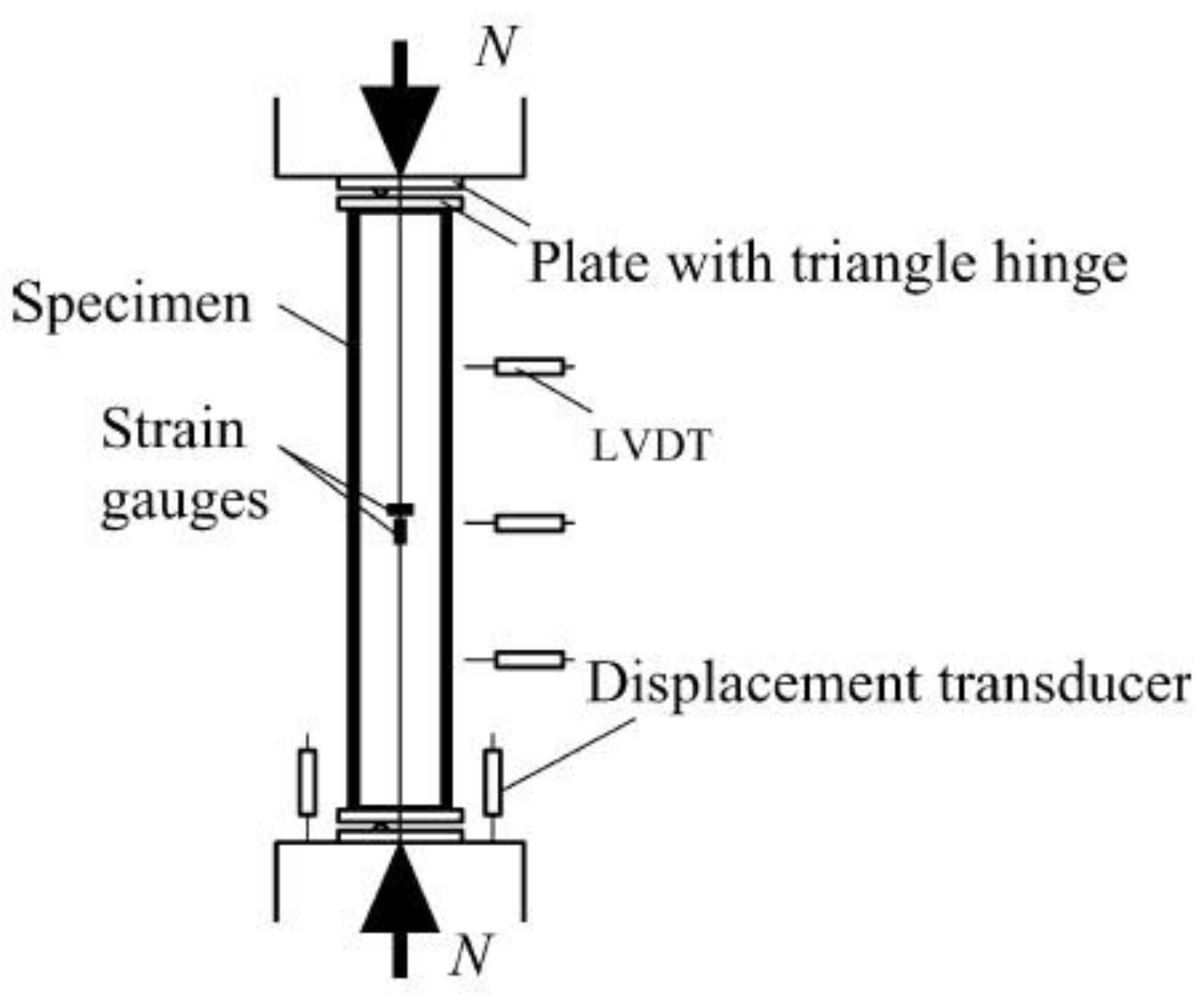
Figure 2.
Boundary conditions and details of the CFST column.
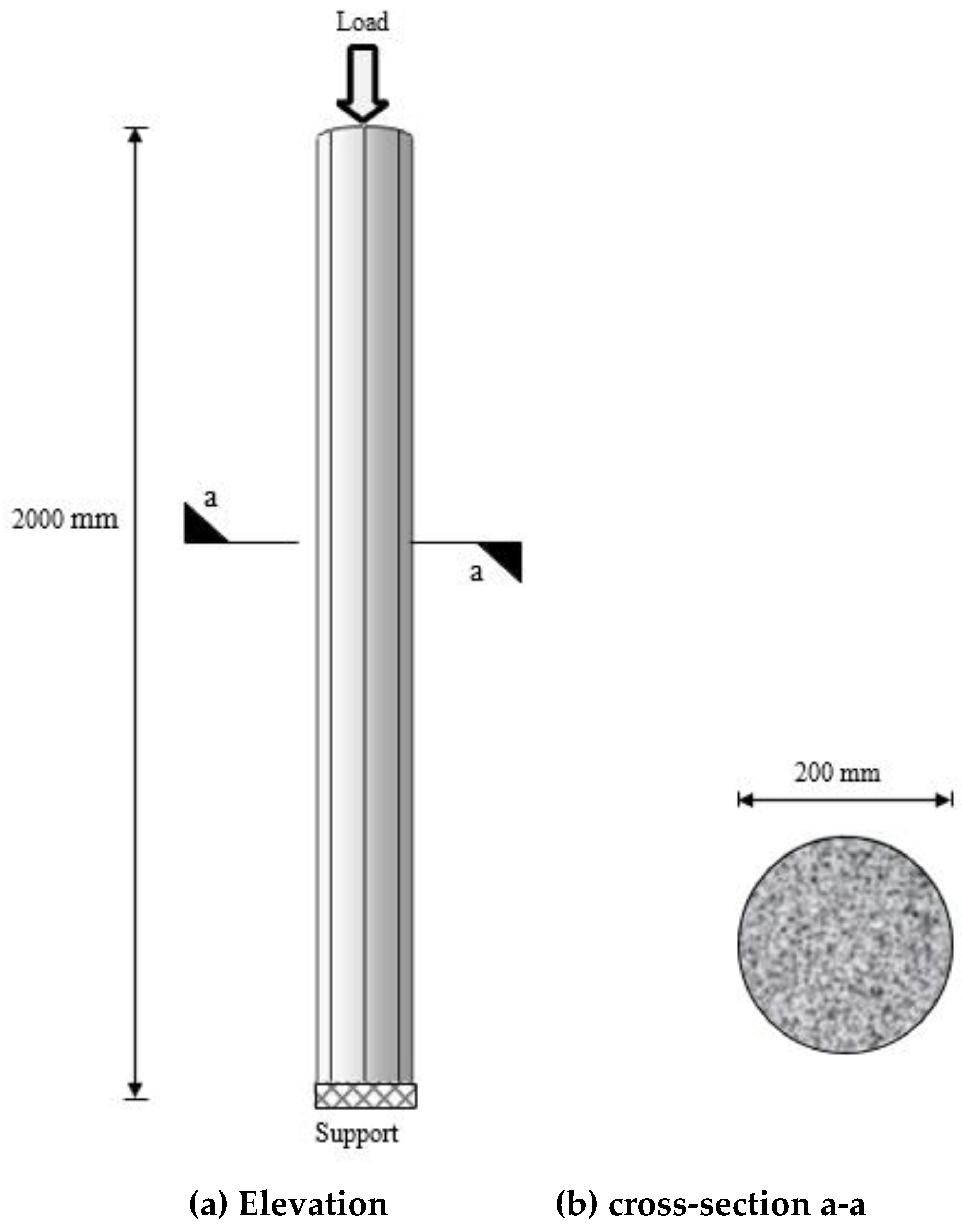
Figure 5.
Stress-strain relationship of concrete material that used in the FE model. Source: (Han and Yao 2004).
Figure 5.
Stress-strain relationship of concrete material that used in the FE model. Source: (Han and Yao 2004).
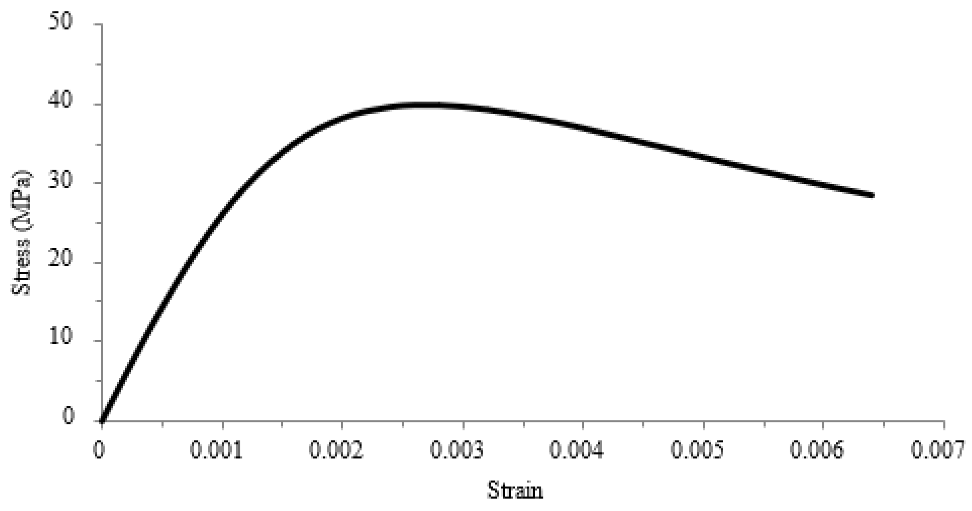
Figure 6.
Typical FE meshing sizes with elements number for the FE models.
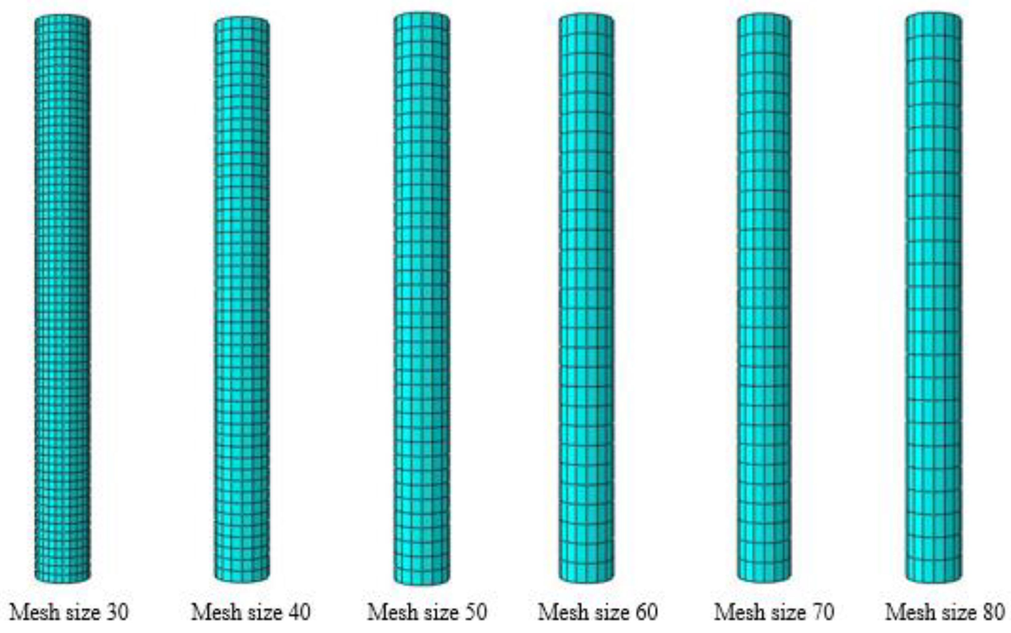
Figure 7.
Finite elements models curves for the convergence study.
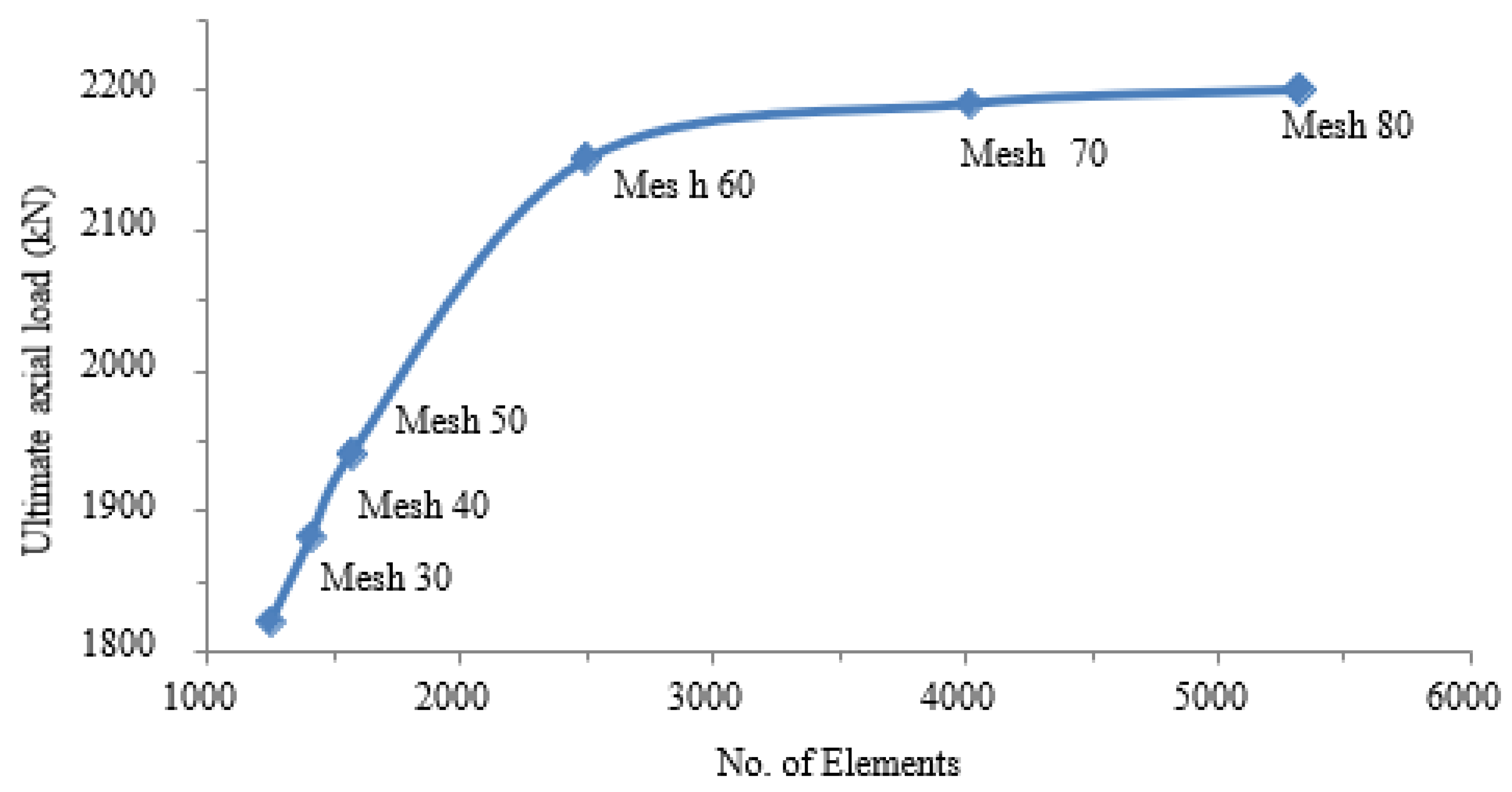
Figure 8.
Axial load – Displacement curve for the circular FE model and existing experimental test.
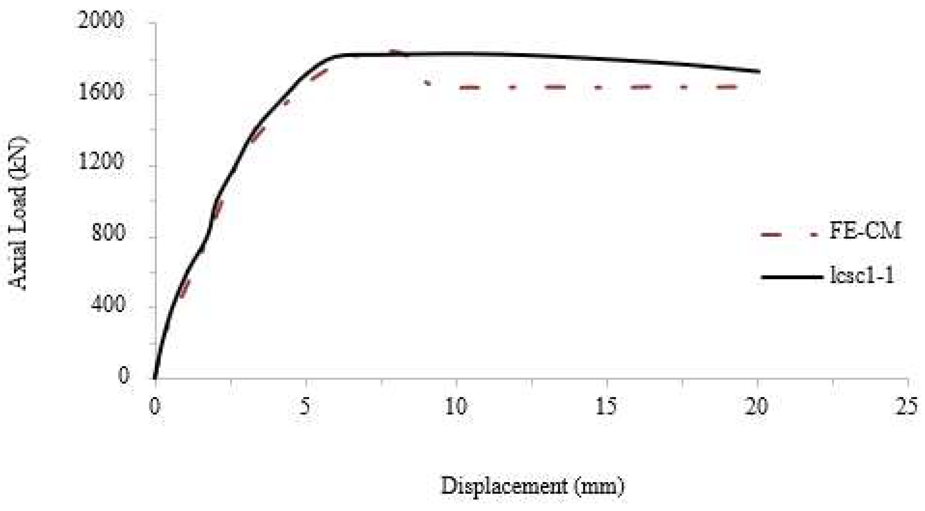
Figure 9.
Axial load – displacement for the circular and square CFST control models.
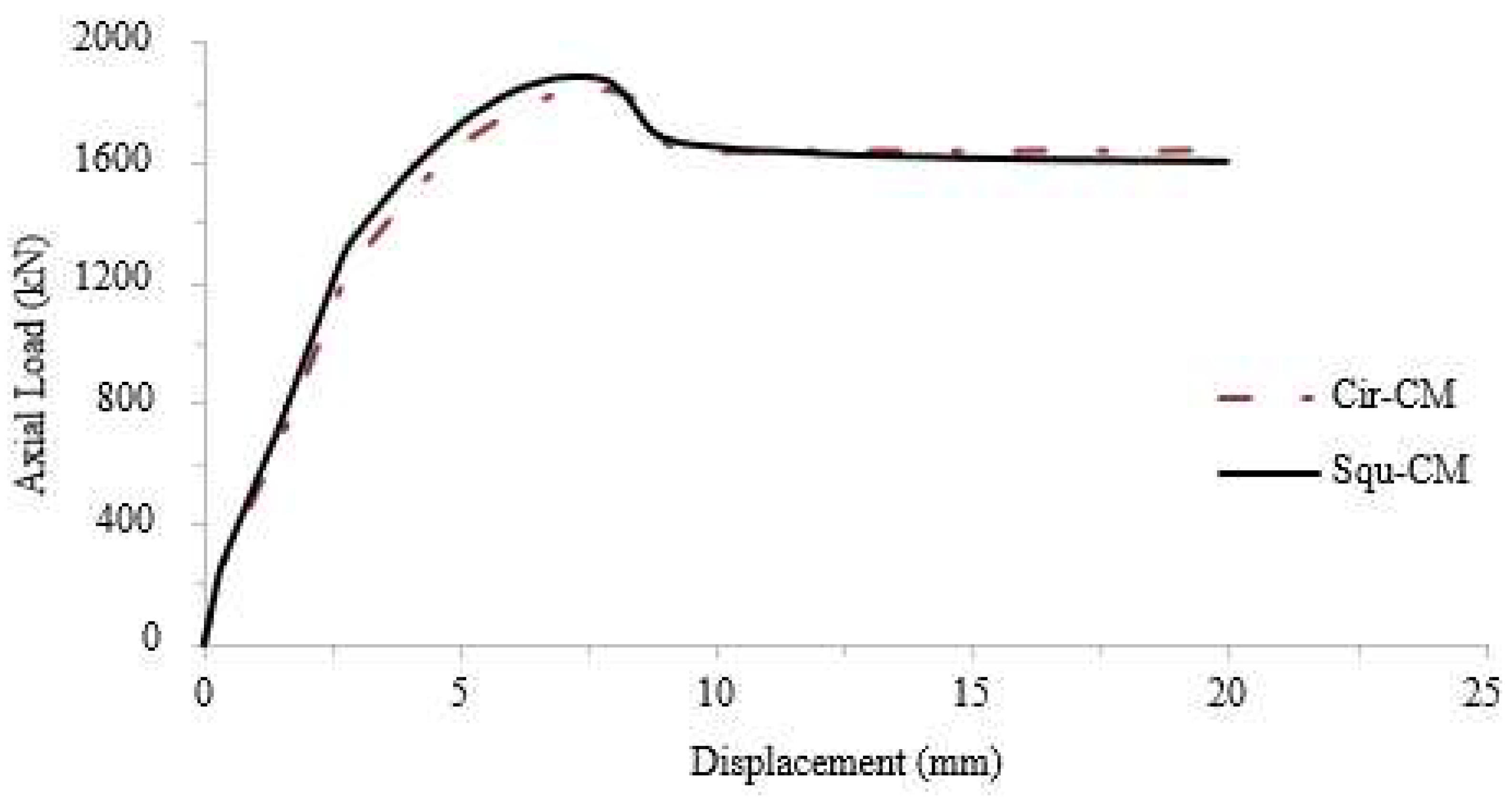
Figure 10.
Details of the FE CFST composite columns with different cross-sections and different CFRP layers number.
Figure 10.
Details of the FE CFST composite columns with different cross-sections and different CFRP layers number.
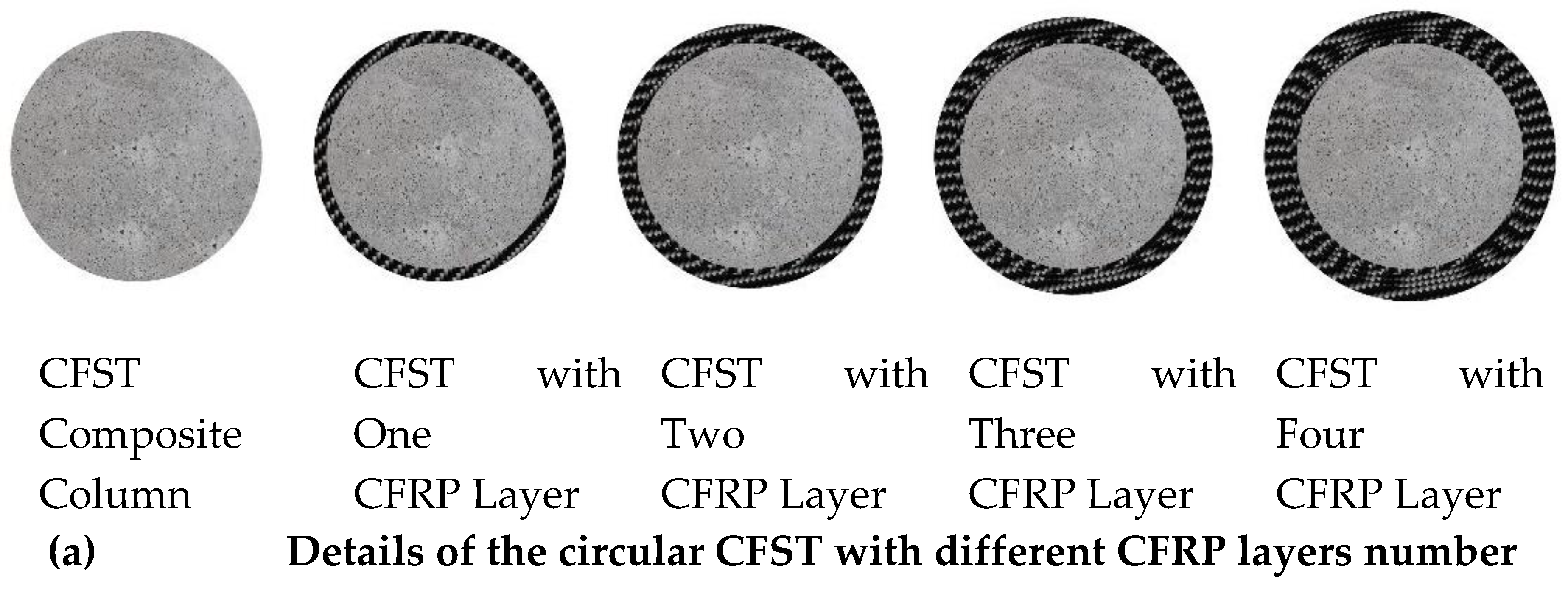
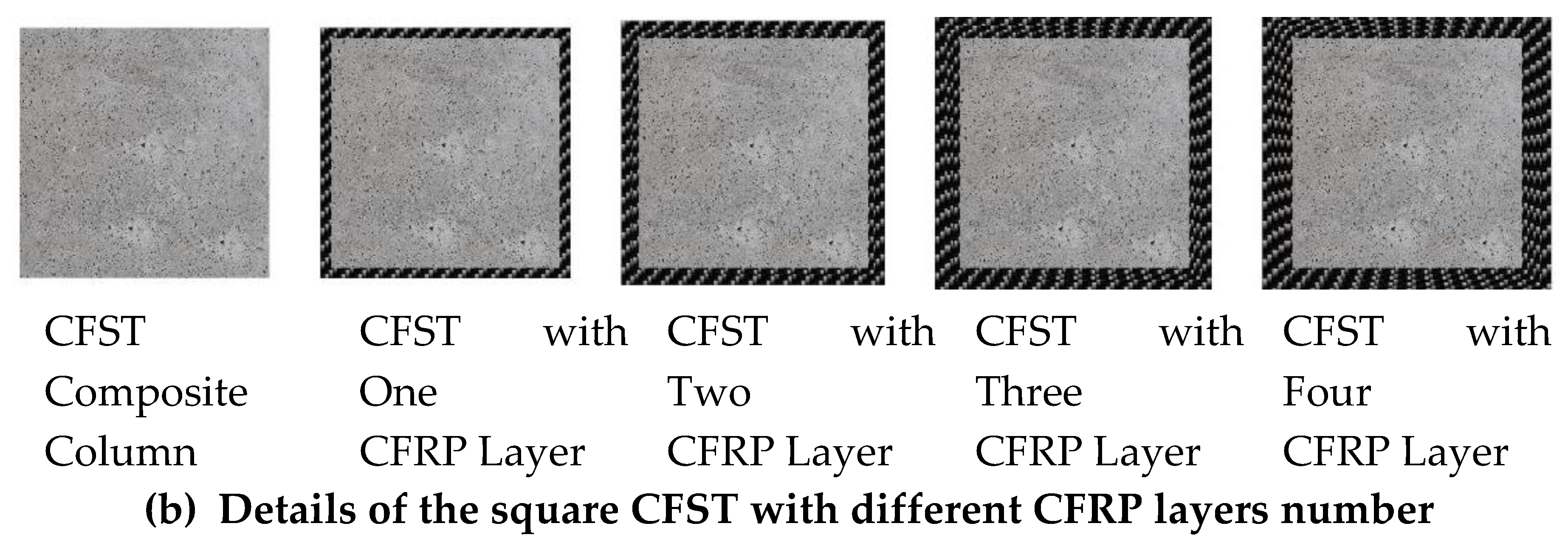
Figure 11.
Axial load – Displacement curve for the control model and FE models with circular cross-sectional shape and different CFRP sheets.
Figure 11.
Axial load – Displacement curve for the control model and FE models with circular cross-sectional shape and different CFRP sheets.
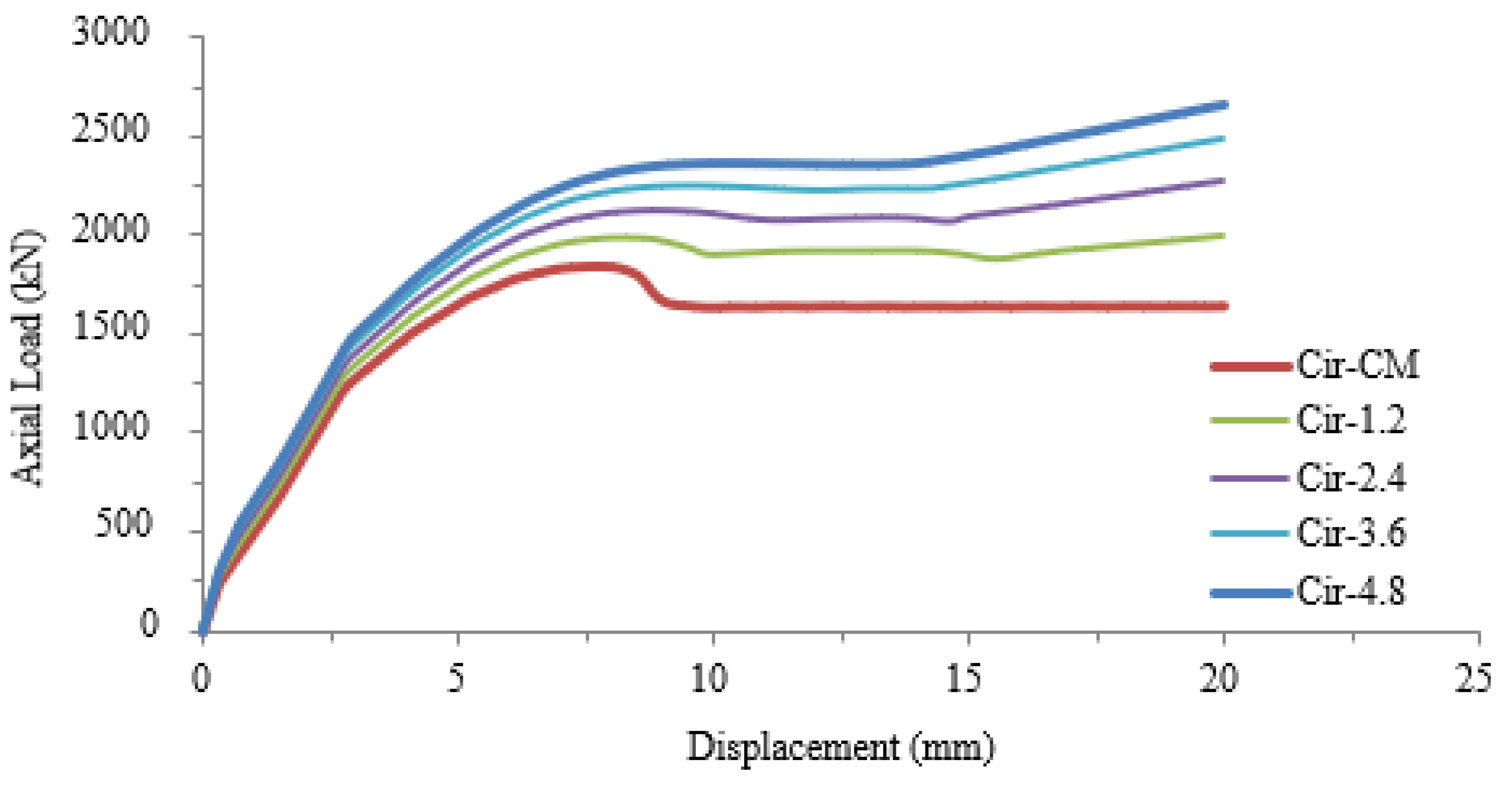
Figure 12.
Axial load – Displacement curve for the control model and FE models with square cross-sectional shape and different CFRP sheets.
Figure 12.
Axial load – Displacement curve for the control model and FE models with square cross-sectional shape and different CFRP sheets.
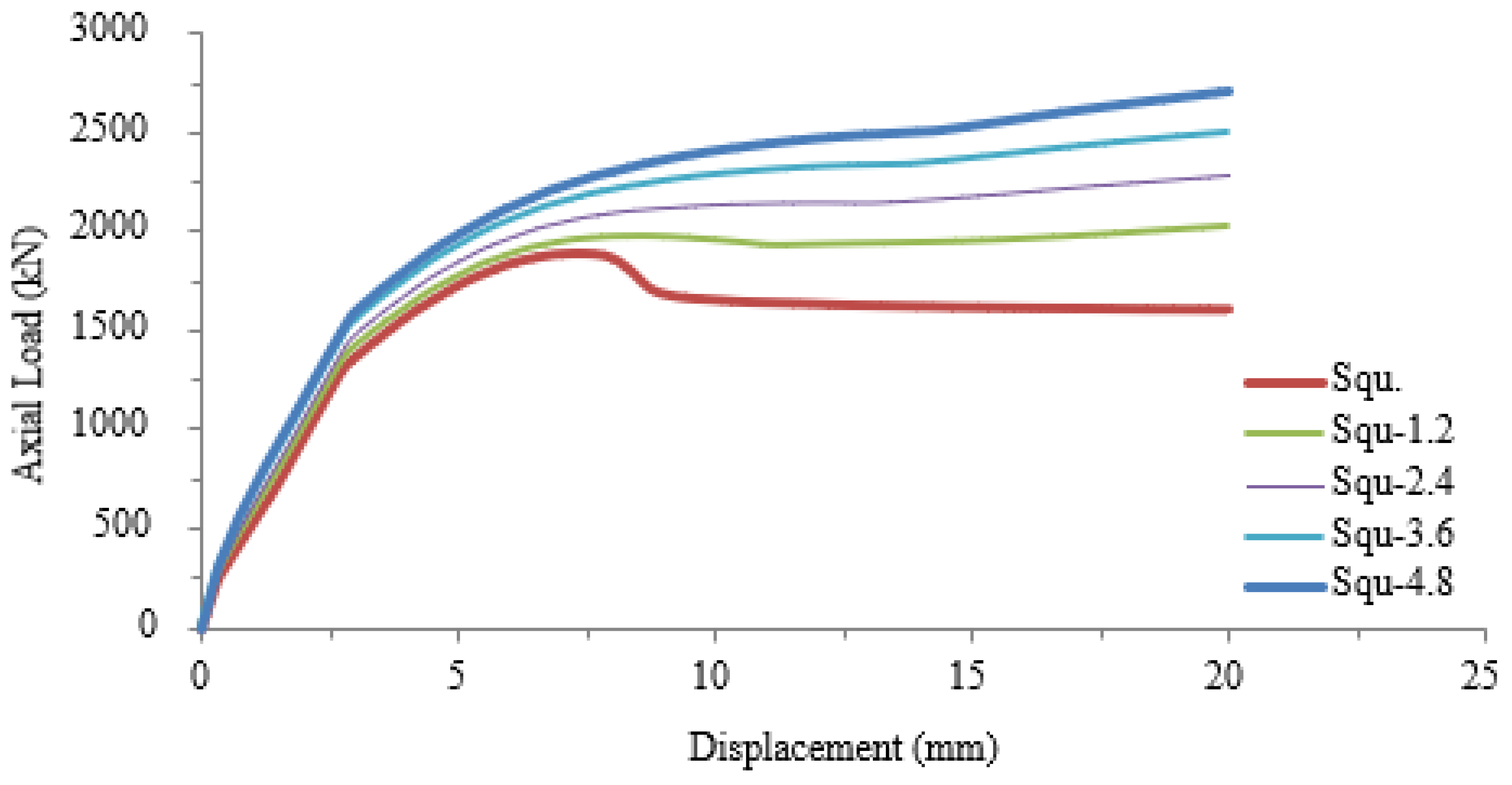
Figure 13.
Details of the FE CFST composite columns with different cross-sections and different CFRP confinement percentages.
Figure 13.
Details of the FE CFST composite columns with different cross-sections and different CFRP confinement percentages.


Figure 14.
Axial load – Displacement curve for the control model and FE models with circular cross-sectional shape and different CFRP confinements.
Figure 14.
Axial load – Displacement curve for the control model and FE models with circular cross-sectional shape and different CFRP confinements.
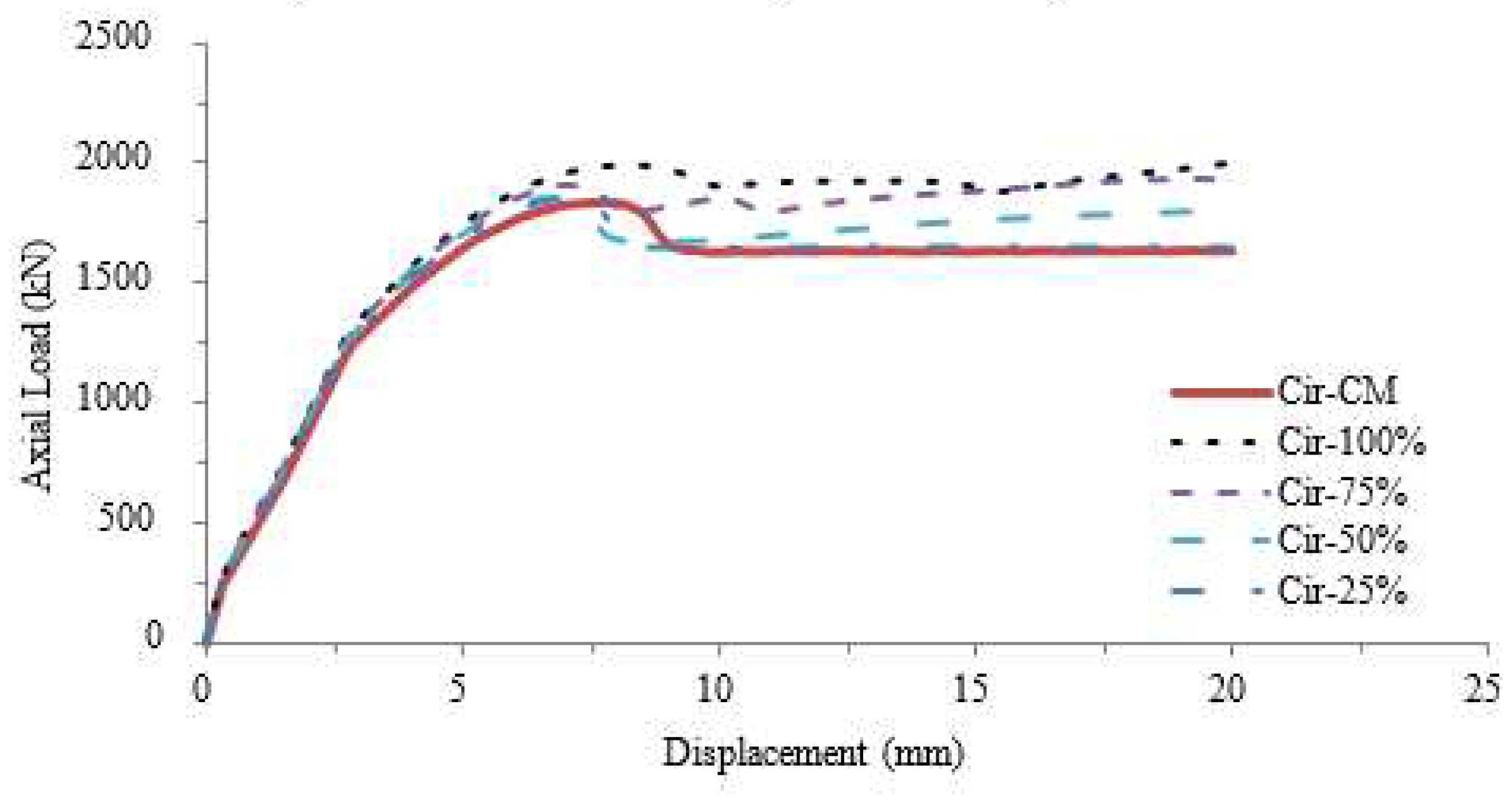
Figure 15.
Axial load – Displacement curve for the control model and FE models with square cross-sectional shape and different CFRP confinements.
Figure 15.
Axial load – Displacement curve for the control model and FE models with square cross-sectional shape and different CFRP confinements.
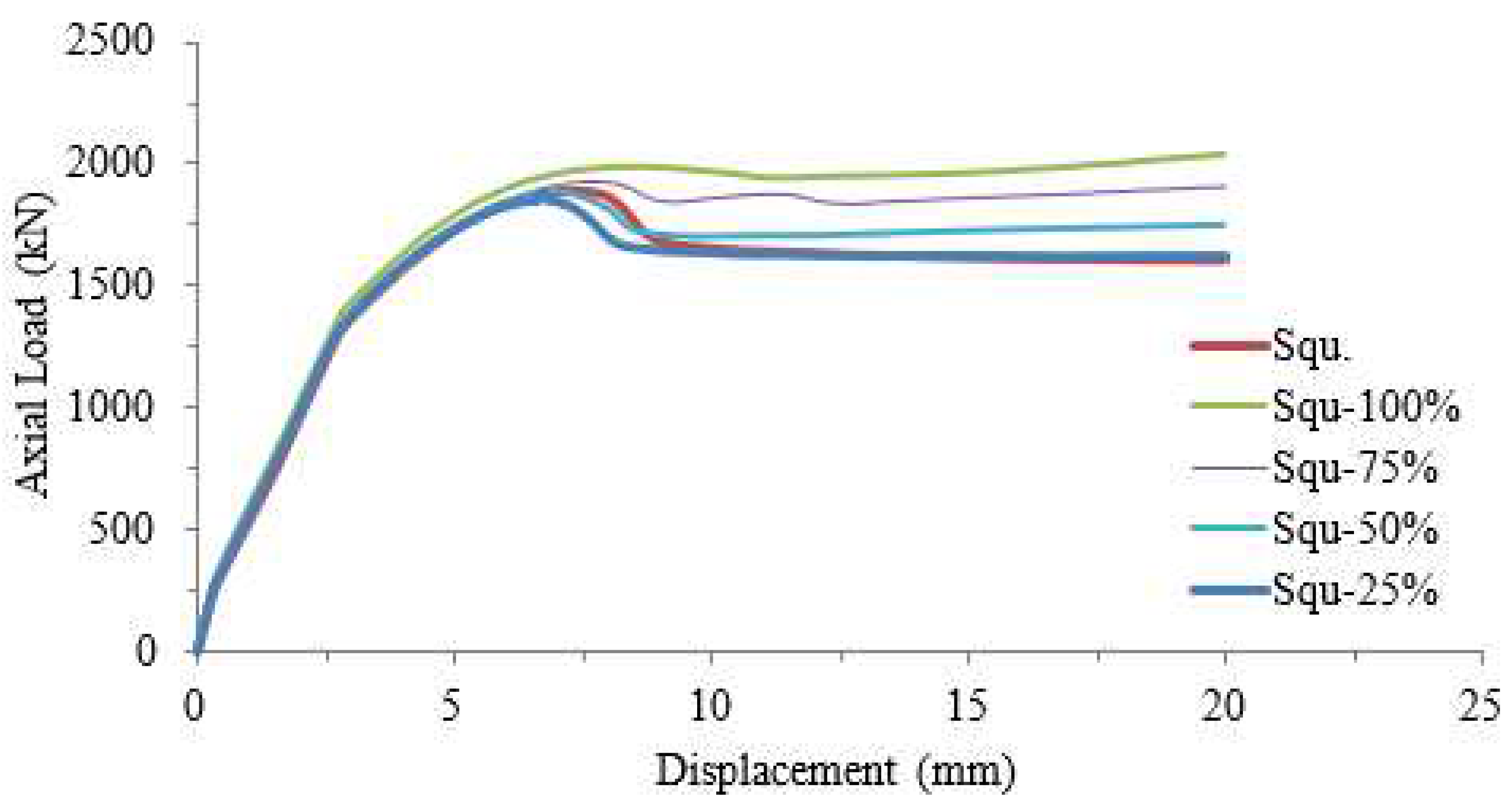
Figure 19.
Stress for the square CFST strengthened with/without CFRP sheets with different lengths.
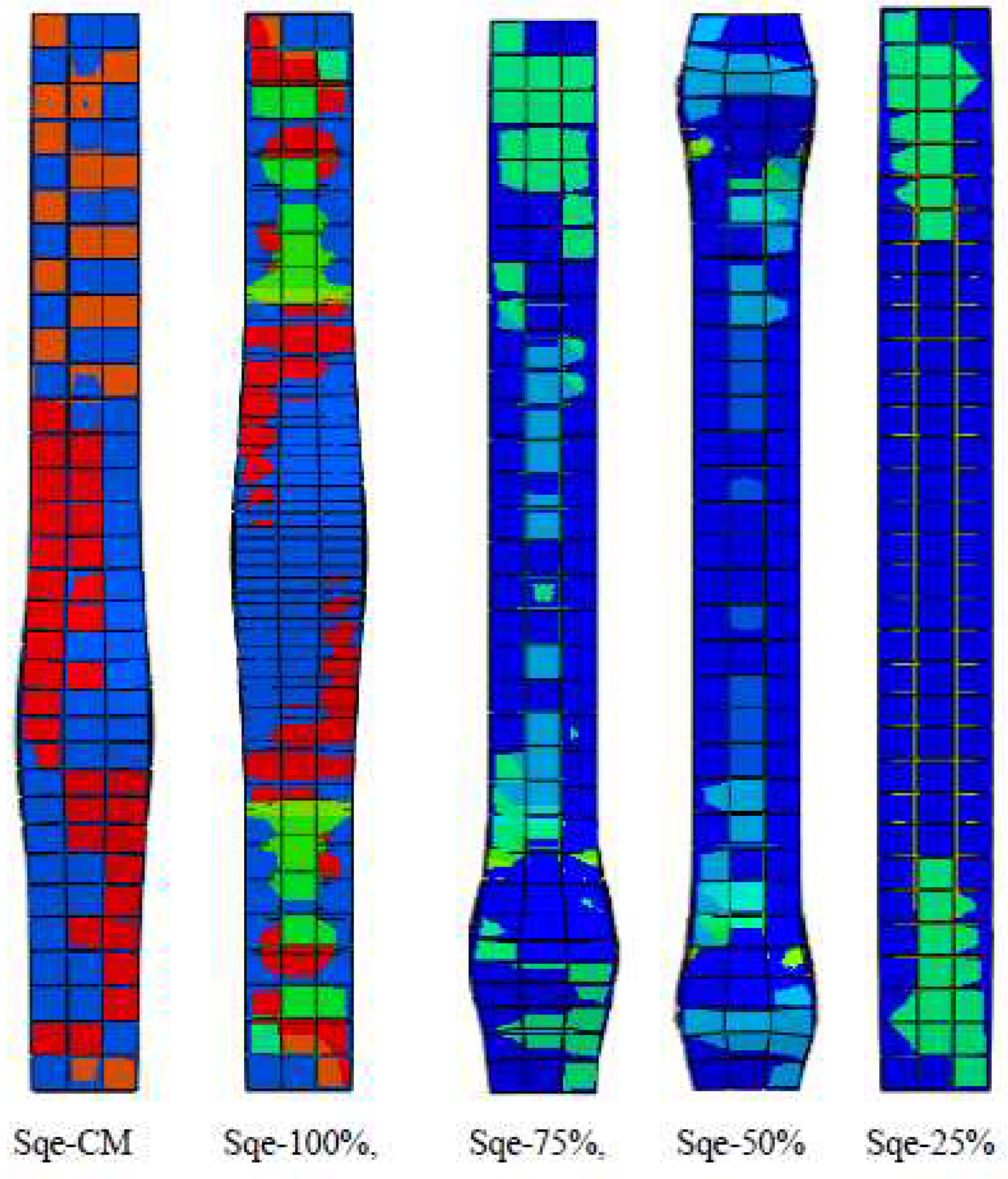
Figure 20.
General view for the experimental specimen and the FE model with circular section after test.
Figure 20.
General view for the experimental specimen and the FE model with circular section after test.
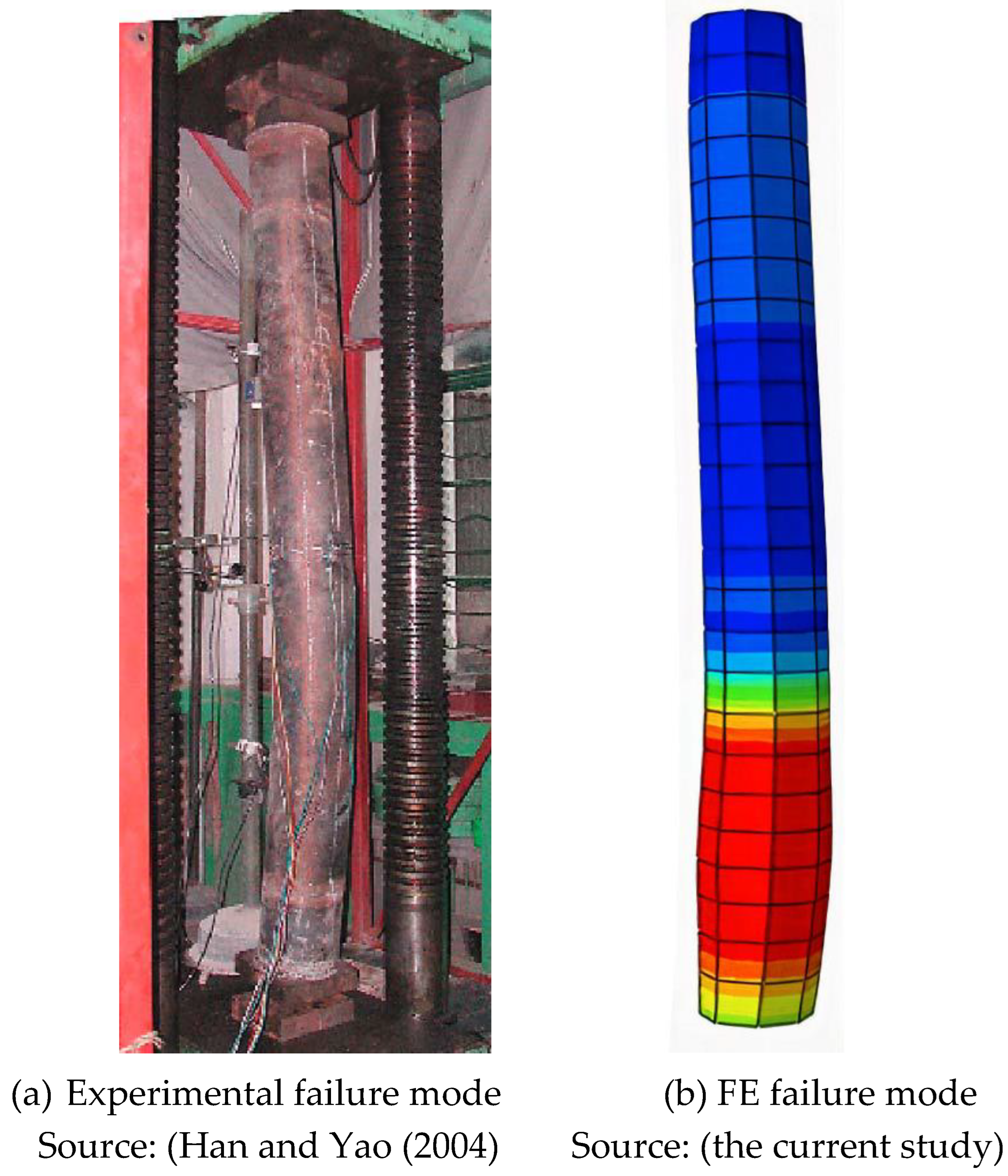

Table 1.
Details of experimental test (specimen 1 which labelled as ICSCI-1).
| Specimens |
L (mm) |
D (mm) |
t (mm) |
Fcu (MPa) |
Ec (MPa) |
Fy (MPa) |
Es (MPa) |
| ICSCI-1 | 2000 | 200 | 3.0 | 40.0 | 37,420 | 303.5 | 206,500 |
Table 2.
Elements type for each part of the FE model.
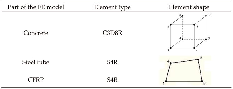 |
Table 3.
Interaction types between the components of the CFST composite columns.
| Surfaces | Interaction type |
| Concrete - Steel | Full tie interaction |
| Steel - CFRP | Cohesive behavior |
Table 4.
Steel material properties.
| Material | Poisson’s ratio | Modulus of elasticity (MPa) |
Yield strength (MPa) |
| Steel | 0.3 | 206,500 | 303.5 |
Table 5.
Concrete material properties.
| Material | Poisson’s ratio | Modulus of elasticity (MPa) |
Compressive strength (MPa) |
| Concrete | 0.2 | 37,420 | 40.0 |
Table 6.
CFRP material properties.
| Material | Thickness (mm) |
Poisson’s ratio | Modulus of elasticity (MPa) |
Tensile strength (MPa) |
|---|---|---|---|---|
| CFRP | 1.2 | 0.4 | 240,000 | 1747 |
Table 7.
Details and properties of the existing experimental composite column.
| Specimens | L (mm) |
D (mm) |
t (mm) |
Fcu (MPa) |
Ec (MPa) |
Fy (MPa) |
Es (MPa) |
|---|---|---|---|---|---|---|---|
| Lcsc1-1 | 2000 | 200 | 3.0 | 40.0 | 37,420 | 303.5 | 206,500 |
Table 8.
Load, displacement and deviation percentages for the FE model and the existing experimental test.
Table 8.
Load, displacement and deviation percentages for the FE model and the existing experimental test.
| Label | Ultimate axial loading (kN) |
Displacement (mm) |
Deviation percentages (%) |
|---|---|---|---|
| Lcsc1-1 | 1818 | 5.5 | - |
| CM | 1841 | 5.8 | +1.2 |
Table 9.
Ultimate axial load, displacement and deviation percentages for the control model and FE models with circular cross-sectional shape and different CFRP sheets number.
Table 9.
Ultimate axial load, displacement and deviation percentages for the control model and FE models with circular cross-sectional shape and different CFRP sheets number.
| Label | Axial loading (kN) |
Displacement (mm) |
Deviation percentages (%) |
| Cir-CM | 1841 | 5.8 | - |
| Cir-1.2 | 1998 | 5.7 | +8.5 |
| Cir-2.4 | 2275 | 5.7 | +23.5 |
| Cir-3.6 | 2488 | 5.6 | +35.1 |
| Cir-4.8 | 2660 | 5.4 | +44.5 |
Table 10.
Ultimate axial load, displacement and deviation percentages for the control model and FE models with square cross-sectional shape and different CFRP sheets number.
Table 10.
Ultimate axial load, displacement and deviation percentages for the control model and FE models with square cross-sectional shape and different CFRP sheets number.
| Label | Axial loading (kN) |
Displacement (mm) |
Deviation percentages (%) |
| Squ | 1883 | 5.8 | - |
| Squ-1.2 | 1979 | 5.7 | +5.1 |
| Squ-2.4 | 2112 | 5.7 | +12.1 |
| Squ-3.6 | 2235 | 5.6 | +18.6 |
| Squ-4.8 | 2713 | 5.4 | +44.0 |
Table 11.
Ultimate axial load, displacement and deviation percentages for the control model and FE models with circular cross-sectional shape and different CFRP confinement percentages.
Table 11.
Ultimate axial load, displacement and deviation percentages for the control model and FE models with circular cross-sectional shape and different CFRP confinement percentages.
| Label | Axial loading (kN) |
Displacement (mm) |
Deviation percentages (%) |
| Cir-CM | 1841 | 5.8 | - |
| Cir-100% | 1998 | 5.7 | +8.50 |
| Cir-75% | 1927 | 5.7 | +4.60 |
| Cir-50% | 1843 | 5.6 | +1.10 |
| Cir-25% | 1842 | 5.6 | +1.01 |
Table 12.
Ultimate axial load, displacement and deviation percentages for the control model and FE models with square cross-sectional shape and different CFRP confinement percentages.
Table 12.
Ultimate axial load, displacement and deviation percentages for the control model and FE models with square cross-sectional shape and different CFRP confinement percentages.
| Label | Axial loading (kN) |
Displacement (mm) |
Deviation percentages (%) |
| Sqe-CM | 1883 | 5.8 | - |
| Sqe-100% | 1979 | 5.7 | +5.10 |
| Sqe-75% | 1934 | 5.7 | +2.63 |
| Sqe-50% | 1885 | 5.6 | +0.06 |
| Sqe-25% | 1884 | 5.6 | +0. 002 |
Disclaimer/Publisher’s Note: The statements, opinions and data contained in all publications are solely those of the individual author(s) and contributor(s) and not of MDPI and/or the editor(s). MDPI and/or the editor(s) disclaim responsibility for any injury to people or property resulting from any ideas, methods, instructions or products referred to in the content. |
© 2023 by the authors. Licensee MDPI, Basel, Switzerland. This article is an open access article distributed under the terms and conditions of the Creative Commons Attribution (CC BY) license (http://creativecommons.org/licenses/by/4.0/).
Copyright: This open access article is published under a Creative Commons CC BY 4.0 license, which permit the free download, distribution, and reuse, provided that the author and preprint are cited in any reuse.
Submitted:
10 December 2023
Posted:
11 December 2023
You are already at the latest version
Alerts
A peer-reviewed article of this preprint also exists.
This version is not peer-reviewed
Submitted:
10 December 2023
Posted:
11 December 2023
You are already at the latest version
Alerts
Abstract
Hollow and concrete-filled steel tubes (CFSTs) are widely used as columns in many structural systems and local buckling can occur when they are subjected to axial compression loading. The critical regions for the local buckling of the columns are near the ends of the column where the moments are the highest. To strengthen the critical regions of the CFSTs the CFRP provides a simple and effective method which used previously as an enhancement for both of strength and ductility. So, this study suggests investigating the axial load behaviour of CFST strengthened with CFRP using FE method after a verification study and then a various parametric studies were carried out to cover the effect of the CFRP layers, number, confinement length and position. The FE results proved that, one CFRP sheet with thickness equal to 1.2 mm was strengthened the composite column by 8.5%, two CFRP sheets with total thickness equal to 2.4 mm was strengthened the composite column by 23.5%, three CFRP sheets with total thickness equal to 3.6 mm was strengthened the composite column by 35.1% and four CFRP sheets with total thickness equal to 4.8 mm was strengthened the composite column by 44.5%. Moreover, this study proved that by strengthened the composite columns with CFRP sheets with different lengths, the axial load resistance was improved by 8.5%, 4.6%, 0.1% and 0.0% for length percentages 100%, 75%, 50% and 25% respectively.
Keywords:
Subject: Engineering - Civil Engineering
1. Introduction
Hollow and concrete-filled steel tubes find widespread application as columns in various structural systems (Al Zand, Badaruzzaman et al. 2015, Contento, Aloisio et al. 2022, Liao, Zeng et al. 2022). These columns can experience local buckling when subjected to axial compression alone or combined with monotonic/cyclic loading (Hilo, Sabih et al. 2022). While buckling modes are crucial failure considerations for concrete-filled steel tubes (CFST) under axial compression and/or bending, similar failure tendencies are observed in thinner cylindrical shells of steel storage silos and tanks. These buckling issues manifest under combined axial compression and internal pressure, both in cyclic and static loading scenarios (Hilo, Sabih et al. 2021, Abdulrazzaq, Hilo et al. 2022, Al Zand, Badaruzzaman et al. 2016). The synergy between concrete and steel in CFST offers benefits: the steel tube confines the concrete and vice versa, effectively delaying local buckling. Primarily employed as columns in buildings and bridges, CFSTs represent economical structural elements, supported by extensive research in the field (Uy 1998, Haj-Ali and Kilic 2002, Han, Tao et al. 2004).
Fiber reinforced polymer (FRP) composites are crafted by embedding continuous fibers within a polymer resin matrix (Al-Zand, Badaruzzaman et al. 2017). Two prevalent FRP systems are recognized: the glass FRP (GFRP) system and the carbon FRP (CFRP) system (Belarbi and Acun 2013). FRP composites boast a high strength-to-weight ratio, exceptional corrosion resistance, and facile on-site handling due to their lightweight nature and adhesive bonding technique (Van Den Einde, Zhao et al. 2003, EL-Fiky, Awad et al. 2022, Kumar, Rangappa et al. 2022). These advantageous characteristics have propelled the adoption of FRP composites in civil engineering. A variety of commercial FRP products, such as bars, sheets, plates, and profiles, have emerged, serving diverse construction purposes: new builds, structural reinforcement/repair, internal reinforcement, and external strengthening. Notably, the external application of FRP composites for strengthening/repairing composite column structures has gained popularity (Ye, Zeng et al. 2022). A novel column design introduced by (Xiao, He et al. 2005) entails confined CFT (CCFT) columns, featuring steel tube segments or FRP jackets at the column's end portions. This approach prevents inward deformation by the concrete core and outward deformation by the jacket, markedly enhancing both ductility and strength in the column's end regions. (Xiao and Wu 2000) validated several anticipated benefits of the CCFT system through initial tests. It's noteworthy that the CCFT system and the tube confinement retrofit method proposed by (Al-Rousan 2022) share a common principle. The use of FRP jackets to mitigate local buckling in circular hollow steel tubes and shells was initially explored at The Hong Kong Polytechnic University, building upon (Wright 1993) concept for FRP confinement of CFT columns.
The literature discussed above clearly demonstrates the potential of CFRP in reinforcing CFSTs. Strengthening CFST using CFRP presents a globally employed method to significantly enhance both strength and ductility. Similar to other structural elements, CFST columns might require upgrading or reinforcement for reasons such as accommodating additional loads or recovering from external damage. In this context, the utilization of CFRP composite sheets has emerged as a highly suitable strategy for reinforcing composite elements in recent times (Ye, Liang et al. 2021). These sheets are user-friendly, exceptionally flexible (moldable into various shapes) (Abdulrazzaq, Hilo et al. 2022), exhibit a higher modulus of elasticity, and possess greater tensile strength compared to steel (Pawlak, Górny et al. 2022).
However, enveloping CFST composite columns with varying lengths and quantities of unidirectional CFRP sheets may not prove to be an economical solution. Additionally, applying CFRP sheets over short spans of CFST composite columns' length could result in failure due to debonding. This is attributed to the substantial peeling stress that arises along the bond interface between the steel and CFRP sheets, particularly under considerable bending stress. Given this context, this study proposes an examination of the axial load behavior of CFRP-strengthened CFST under diverse parametric scenarios. This investigation aims to encompass the impact of factors like the number of CFRP layers, confinement length, and positioning, thereby providing a comprehensive understanding.
2. Experimental Study
The methodology of this research was described in three different stages: the first stage was, compare the results of the FE analysis using ABAQUS software (Hibbitt, Karlsson et al. 2011) with results of an existing experimental test done by (Han and Yao 2004). Second stage was, generate a parametric study to cover the effect of the CFRP layers, length and positions on the axial load behaviour of the CFST composite columns strengthened with CFRP by designing many different FE models. Third stage was, generate the FE analysis results, conclusions and suggestions.
An existing experimental study done by (Han and Yao 2004) was chosen for the verification in this study. Thirty-eight specimens, including 18 stub columns and 20 beam columns were tested. The main parameters varied in the tests are: (1) column section type, circular and square; (2) tube diameter (or width) to thickness ratio, from 33 to 67; and (3) load eccentricity ratio (e/r), from 0 to 0.3 mm.
Among all of the experimental models (38 models), this study suggests to choose specimen 1 which labelled as (ICSCI-1) in the existing study. This study selects the specimen 1 as an experimental test to verify the FE analysis only, so it was suggested to avoid the other specimens which were designed with different details and not valid for the main objective of this research. Brief details of the experimental specimen were presented in Table 1 and the cross-section was presented in Figure 1.
3. Finite Element Modelling
Nonlinear full scale FE models were prepared, designed and analyzed using ABAQUS software (Hibbitt, Karlsson et al. 2011) in order to investigate the structural behaviour of CFST composite columns strengthened with CFRP sheets. Boundary conditions, elements types, parts, meshing, and material modelling, of the FE models were presented in details in this study.
3.1. Geometry, element assignment and interaction
The primary Finite Element (FE) model was crafted using ABAQUS software (Hibbitt, Karlsson et al. 2011), adhering to the specifications of the experimental test, including loading system, test arrangement, and boundary conditions. This model aimed to simulate CFST composite columns reinforced with CFRP sheets. Notably, the FE simulation employed a comprehensive scale model (depicted in Figure 2) for all CFST composite columns.
In this investigation, a progressive monotonic analysis was conducted using the displacement load approach. Loading was incrementally applied to specific points, increasing at a controlled rate of 0.1 mm/s. This process continued until the ultimate capacity of the CFRP-strengthened CFST composite columns was attained. The loading system employed in Abaqus supported this procedure.
Within the ABAQUS software, an array of element types is available in the Standard Element Library. For this study, the choice was made to utilize the S4R element type for the steel tube and CFRP components. In parallel, the element type C3D8R was chosen to represent the concrete material. For a more comprehensive breakdown of element selections for each segment of the FE model, refer to Table 2.
Ensuring alignment between the outcomes of the experimental test and the FE model necessitates meticulous consideration of surface interactions among the constituent parts of the composite columns, including concrete, steel tube, CFRP, and adhesive substances. This stands out as a pivotal and intricate aspect of parameter selection.
Therefore, this study adopts the ‘cohesive behaviour’ technique which it is breakable nodes along the surface interaction between the steel tube and the CFRP. The full tie interaction technique was selected to represent the surface interaction between the inner surface of the steel tube and the outer surface of concrete, because no slip is assumed to occur along the surface interaction due to bending; the reason was the tube totally confines the concrete core at all of the loading stages. For more details Table 3 presented summery of the interaction type between the parts of the composite column FE model.
3.2. Properties of Materials
This section outlines the material properties utilized in the study, offering a comprehensive insight into their integration within the FE models.
- Steel
The material properties of steel adopted in the FE models precisely mirrored those from the experimental parameters. These properties encompass Poisson's ratio, modulus of elasticity, and yield strength, with values directly sourced from the pre-existing experimental study. Specifically, these values were 0.3, 206,500 MPa, and 303.5 MPa, respectively, as detailed in Table 4. Notably, the steel material is characterized as an elastic-plastic isotropic substance. Implementing these mechanical attributes in the FE models using Abaqus involved opting for the elastic-isotropic approach to define mechanical properties. The tri-linear stress-strain model exhibited in Figure 4, as presented by (Han and Yao 2004), was embraced in this study to estimate stress-strain correlations within the FE models.
Figure 4.
Stress-strain curve of steel material used in the FE model. Source: (Han and Yao 2004).
- Concrete
The concrete properties adopted in this study were directly extracted from the experimental tests. Compressive strength was assigned a value of 40 MPa, Poisson's ratio 0.2, and the modulus of elasticity 37,420 MPa, as outlined in Table 5. Concrete, in its essence, is an isotropic substance. To represent its mechanical elasticity in the FE models through Abaqus, the elastic-isotropic approach was employed to define the modulus of elasticity and Poisson's ratio. Additionally, the mechanical-plasticity properties were identified through the selection of the concrete damaged plasticity option. Figure 5 depicts the stress-strain relationship for concrete, adopting the same equations as (Sundarraja and Prabhu 2011).
- CFRP sheet
For enhancing CFST columns, unidirectional CFRP sheets were introduced. Specifically, the MBrace 240 type of CFRP sheet was utilized, characterized by a modulus of elasticity of 240,000 GPa, ultimate tensile strength of 1747 MPa, sheet thickness of 1.2 mm, and Poisson's ratio of 0.4, as provided in Table 6. Notably, CFRP material follows an elastic-brittle nature. Thus, its mechanical properties are represented through the fiber reinforced polymer-Hashin Damage model (Al-Zand, Badaruzzaman et al. 2017). This material is treated as orthotropic, and its elastic-engineering constants are harnessed to determine key elasticity properties, including the modulus of elasticity, Poisson's ratio, and shear modulus.
4. Convergence Study
Convergence study was generated in this study to find the suitable meshing for the FE modelling in non-linear analysis for the CFST composite columns. To verify the finer meshing for the models, six different meshes sizes were applied and analyzed, the meshing sizes were 30, 40, 50, 60, 70 and 80 mm as presented in Figure 6. These meshing sizes were with different ultimate axial loading. This study found that the axial loading resistance between the model with 60 mm meshing size and 70 mm meshing size had no considerable difference through comparing the ultimate axial load for each mesh size, as presented in Figure 7. The ultimate axial loads for the FE model with 50 mm meshing size was 2,161 kN and it was equal to 1841kN for the FE model with 60 mm meshing size which it was very near to the experimental ultimate axial loading 1818 kN. This study suggests choosing meshing size 60 mm as a meshing size for all of the rest of the composite columns FE models because of the high accuracy and less analysis time for the models.
5. Verification Study
An existing experimental study done by Han and Yao (2004) was chosen for the verification in the current study. This study suggests choosing specimen 1 which labelled as (ICSCI-1) in the existing study. Brief details of the existing experimental specimen were presented in Table 7.
A FE model was designed and analyzed with parameters exactly similar to the experimental test and results were compared. The experimental test was labelled as Lcsc11, and the FE model labelled as Cir-CM. The ultimate axial loading for the experimental test was 1818 kN with 5.5 mm displacement, and the ultimate axial loading for the FE model was 1841 kN with displacement 5.8 mm as presented in Table 8.
The accuracy of the FE verification was achieved through the comparison and the deviation percentage was 1.2 % only as presented in Figure 8 which it considered very close to the experimental results. The verified FE model (CM) was selected as a control model for all of the parametric study.
It was suggested in this study to investigate the effect of CFRP sheets on the square CFST composite column as well. Therefore, a FE model was analyzed and designed and the properties of the FE Model were exactly similar to the experimental test. The cross-section area for the Square CFST was 30,625 mm2 and it was similar to the Circular CFST cross-section area 31,415.9 mm2. Moreover, the moment of inertia for both of the cross-section was very close as well which it were around 78,157,552. As a result, Figure 9 presenting the axial load – displacement for the circular and square CFST to prove that these two different cross-sections were with very similar load displacement behaviour.
6. Parametric Studies
This study suggests investigating the effect of various parameters on the axial load behaviour of circular and square CFST composite columns strengthened with CFRP to present more information about using the CFRP as a strengthening method for the composite columns. The main parameters were the effect of CFRP layers numbers and positions and confinement length for both cross-sections circular and square.
6.1. Effect of CFRP layers numbers
It was suggested to investigate the effect of the CFRP layers numbers on the axial load behaviour of circular and square CFST composite columns to present clear understanding about the CFRP positive effect on the cross-section shape of the CFST composite column.
Eight (8) different FE models were designed and, analyzed and divided into two groups, the first group was four (4) FE models designed with circular cross-sectional shape, the first FE model was with 1 CFRP layer and labelled as Cir-1.2, second FE model was with 2 CFRP layers and labelled as Cir-2.4, third FE model was with 3 CFRP layers and labelled as Cir-3.6 and the fourth FE model was with 4 CFRP layers and labelled as Cir-4.8. The second group, was another four (4) FE models but this time the models designed with square cross-sectional shape, the first FE model was with 1 CFRP layer and labelled as Squ-1.2, second FE model was with 2 CFRP layers and labelled as Squ-2.4, third FE model was with 3 CFRP layers and labelled as Squ-3.6, and the fourth FE model was with 4 CFRP layers and labelled as Squ-4.8. Figure 10 (a and b) presenting the cross-sectional shapes of the FE CFST composite columns models with different CFRP layers number.
To assess the influence of CFRP sheet quantity on the axial load behavior of CFST composite columns, the ultimate axial load of the initial group of FE models (with circular cross-sectional shape) was juxtaposed with the ultimate axial load of the control model (Cir-CM). The ultimate axial load values were as follows: 1998 kN, 2275 kN, 2488 kN, and 2660 kN for FE models Cir-1.2, Cir-2.4, Cir-3.6, and Cir-4.8, respectively. These results are tabulated in Table 9, and the corresponding displacement was approximately 5.6 mm.
The FE results proved that, number of CFRP sheet was positively affect on the axial load behaviour of the CFST composite column with circular cross-sectional shape. One CFRP sheet with thickness equal to 1.2 mm was strengthened the composite column by 8.5%, two CFRP sheets with total thickness equal to 2.4 mm was strengthened the composite column by 23.5%, three CFRP sheets with total thickness equal to 3.6 mm was strengthened the composite column by 35.1% and four CFRP sheets with total thickness equal to 4.8 mm was strengthened the composite column by 44.5% as presented in Figure 11.
To evaluate the impact of varying CFRP sheet quantities on the axial load behavior of CFST composite columns, the ultimate axial load of FE models featuring square cross-sectional shapes was juxtaposed with that of the control model (Squ). The ultimate axial load values stood at 1979 kN, 2112 kN, 2235 kN, and 2713 kN for FE models Squ-1.2, Squ-2.4, Squ-3.6, and Squ-4.8, respectively. These findings, detailed in Table 10, exhibited a consistent displacement of around 7.5 mm across all FE models.
The FE results proved that, number of CFRP sheet was positively affect on the axial load behaviour of the CFST composite column with square cross-sectional shape. One CFRP sheet with thickness equal to 1.2 mm was strengthened the composite column by 5.1%, two CFRP sheets with total thickness equal to 2.4 mm was strengthened the composite column by 12.1%, three CFRP sheets with total thickness equal to 3.6 mm was strengthened the composite column by 18.6% and four CFRP sheets with total thickness equal to 4.8 mm was strengthened the composite column by 44.0% as presented in Figure 12.
The stress of the FE CFST models strengthened with different CFRP sheets was presented in Figure 12. The failure mode for the FE models was local at the ends of the CFST composite columns and the stress was uniformly distributed on the CFRP sheets, meanwhile the highest stress for the control models (no CFRP) was local buckling at the bottom end of the CFST composite columns and that lead to concrete crash and steel tube local buckling at the same position. This parametric proved that the CFRP sheets decrease the local buckling and enhanced the concrete compression resistance and increase the ultimate axial loading as presented in Figure 12.
6.2. Effect of CFRP Confinement Length
The confinement effect of the CFRP sheets on the axial load behaviour of the CFST composite columns was studied as well and another eight (8) FE models were designed and analyzed and divided into two groups, the first group was with four FE models designed with circular cross-sectional shape, the first FE model was with 50% CFRP sheets confinement of the CFST composite columns total length and positioned in the mid span, second FE model was with 75% CFRP sheets confinement of the CFST composite columns total length and positioned in the mid span as well, third FE model was with 100% CFRP sheets confinement of the CFST composite columns total length positioned in mid span also and the fourth FE model was with two 25% CFRP sheets confinement of the CFST composite columns total length the first it was 25% in the top side and the second 25% in the bottom side as presented in Figure 13-(a). the second group was with different four FE models designed with square cross-sectional shape, and the CFRP sheets confinement of the CFST composite columns were designed exactly similar to the first group as presented in Figure 13-(b).
Figure 12.
Stress for the circular CFST strengthened with/without CFRP sheets with different layers.
Figure 12.
Stress for the circular CFST strengthened with/without CFRP sheets with different layers.
The results proved that the ultimate axial load for the FE models of the first group (circular cross-section) was equal to 1998, 1972, 1843 and 1842 kN, respectively for the models Cir100%, Cir-75%, Cir-50% and Cir-25% and it was with displacement 5.7 mm for all of these FE models as presented in Table 11. Improvement percentages were recorded for the FE models when strengthened with CFRP with different lengths ant it was equal to 8.5, 4.6, 1.1 and 1.01% respectively for the FE models Cir-100%, Cir-75%, Cir-50% and Cir-25% as presented in Figure 14.
The results proved that the ultimate axial load for the second group (square cross-sectional shape) of the FE models was equal to 1997, 1934, 1885 and 1884 kN, respectively for the FE models Sqe-100%, Sqe-75%, Sqe-50% and Sqe-25% and the with displacement was around 5.7 mm for all of these FE models as presented in Table 12. Improvement percentages were recorded for the FE models when strengthened with CFRP with different lengths and it was equal to 5.10, 2.63, 0.06 and 0.002%, respectively, for the FE models Sqe-100%, Sqe-75%, Sqe-50% and Sqe-25% as presented in Figure 15.
The stress of the FE square CFST composite columns strengthened with CFRP sheets with different lengths was presented in Figure 19. The failure mode for the FE models Sqe100%, Sqe-75%, Sqe-50% and Sqe-25% was local at the area which it was unconfined with CFRP meanwhile the failure mode for the control models Sqe-CM (no CFRP) was local buckling at the mid span. The FE results proved that the CFRP sheets decrease the local buckling and increases the ultimate axial loading.
7. Failure Mode and Discussion
In this section, the study delves into the failure mode predictions between the FE analysis and their comparison with the results of an existing experimental study conducted by Han and Yao (2004).
The primary objective of this study was to assess the accuracy of the FE analysis in predicting the failure modes of CFST composite columns strengthened with CFRP sheets. The verification process involved selecting a specific specimen, labeled as ICSCI-1 in the experimental study, to serve as the experimental benchmark for the FE analysis of the current study. In the verification phase, the study opted to use specimen ICSCI-1 from the existing experimental dataset, as it closely aligned with the objectives of our research. This specimen was subjected to various parameters, including column section type (circular), tube diameter to thickness ratio, and load eccentricity ratio. The decision to focus on specimen ICSCI-1 ensured the compatibility of the FE analysis with the experimental data.
The results of the FE analysis exhibited an exceptionally close alignment with the experimental findings, both in terms of ultimate axial load behavior and failure mode prediction. Figure 20 show cases a visual representation of this remarkable agreement between the FE analysis and the experimental test. The figure highlights the accuracy of the FE model in capturing the specific failure mode exhibited by specimen ICSCI-1.
This study has provided a comprehensive assessment of the axial load behavior of CFST composite columns strengthened with CFRP sheets. The FE analysis's ability to accurately predict the failure mode, as confirmed through experimental validation, signifies its robustness and reliability.
8. Conclusion
This study offers a comprehensive analysis of the axial load behavior of circular and square CFST composite columns, augmented by varying quantities of CFRP sheets and distinct confinement percentages. To validate the fidelity of the FE analysis, a comparison was drawn against the findings of a prior experimental test conducted by Han and Yao (2004). Subsequently, this investigation meticulously designed and analyzed 18 distinct FE models utilizing Abaqus software, encompassing four distinct parametric studies. These studies focused on exploring the impact of CFRP sheet counts and confinement lengths across differing cross-sectional shapes.
The FE results notably showcased that employing a single CFRP sheet with a thickness of 1.2 mm bolstered the composite column by 8.5%. Meanwhile, the implementation of two CFRP sheets, totalling 2.4 mm in thickness, led to a 23.5% enhancement in column strength. Elevating the number of CFRP sheets to three, with a combined thickness of 3.6 mm, resulted in a remarkable 35.1% reinforcement. Similarly, the application of four CFRP sheets, summing to a total thickness of 4.8 mm, yielded an impressive 44.5% increase in column strength. Furthermore, it was observed that strengthening composite columns with varying lengths of CFRP sheets led to improvements of 8.5%, 4.6%, 0.1%, and 0.0% for length percentages of 100%, 75%, 50%, and 25%, respectively.
This study also proposes several promising avenues for future research. Firstly, it suggests investigating the axial load behavior of composite columns filled with lightweight concrete or alternative environmentally-friendly materials, while concurrently evaluating the impact of CFRP sheets as a strengthening technique. Secondly, the study advocates delving into the axial load behavior of composite columns fortified with steel plates as an alternative to CFRP. This investigation could encompass varying factors like steel yield, thickness, or confinement area, aiming to mitigate the costs associated with CFRP repair and strengthening approaches.
Looking ahead, future research avenues could explore the axial load behavior of composite columns filled with alternative materials and investigate the potential of steel plates as an alternative to CFRP for strengthening purposes. These directions offer opportunities to enhance the performance and cost-effectiveness of composite column strengthening techniques.
References
- Abdulrazzaq, M. M., S. J. Hilo, S. M. Sabih, S. A. Hilmi, A. W. Al-Zand and M. M. Ali (2022). "Numerical investigation for the flexural load behaviour of profiled composite slab strengthened with CFRP." Materials Today: Proceedings 61: 1115-1125. [CrossRef]
- Al-Rousan, R. Z. (2022). "Cyclic lateral behavior of NLFEA heat-damaged circular CFT steel columns confined at the end with CFRP composites." Case Studies in Construction Materials 17: e01223. [CrossRef]
- Al-Zand, A. W., W. H. W. Badaruzzaman, A. A. Mutalib and S. J. Hilo (2017). "Modelling the delamination failure along the CFRP-CFST beam interaction surface using different finite element techniques." Journal of Engineering Science and Technology 12(2): 214-228.
- Al Zand, A. W., W. H. W. Badaruzzaman, A. A. Mutalib and S. J. Hilo (2016). "The enhanced performance of CFST beams using different strengthening schemes involving unidirectional CFRP sheets: An experimental study." Engineering Structures 128: 184-198. [CrossRef]
- Al Zand, A. W., W. H. W. Badaruzzaman, A. A. Mutalib and A. Qahtan (2015). "Finite element analysis of square CFST beam strengthened by CFRP composite material." Thin-Walled Structures 96: 348-358. [CrossRef]
- Belarbi, A. and B. Acun (2013). "FRP systems in shear strengthening of reinforced concrete structures." Procedia Engineering 57: 2-8. [CrossRef]
- Contento, A., A. Aloisio, J. Xue, G. Quaranta, B. Briseghella and P. Gardoni (2022). "Probabilistic axial capacity model for concrete-filled steel tubes accounting for load eccentricity and debonding." Engineering Structures 268: 114730. [CrossRef]
- EL-Fiky, A. M., Y. A. Awad, H. M. Elhegazy, M. G. Hasan, I. Abdel-Latif, A. M. Ebid and M. A. Khalaf (2022). "FRP Poles: A State-of-the-Art-Review of Manufacturing, Testing, and Modeling." Buildings 12(8): 1085.
- Haj-Ali, R. and H. Kilic (2002). "Nonlinear behavior of pultruded FRP composites." Composites Part B: Engineering 33(3): 173-191. [CrossRef]
- Han, L.-H., Z. Tao, H. Huang and X.-L. Zhao (2004). "Concrete-filled double skin (SHS outer and CHS inner) steel tubular beam-columns." Thin-walled structures 42(9): 1329-1355. [CrossRef]
- Han, L.-H. and G.-H. Yao (2004). "Experimental behaviour of thin-walled hollow structural steel (HSS) columns filled with self-consolidating concrete (SCC)." Thin-Walled Structures 42(9): 1357-1377. [CrossRef]
- Hibbitt, H., B. Karlsson and P. Sorensen (2011). "Abaqus analysis user’s manual version 6.10." Dassault Systèmes Simulia Corp.: Providence, RI, USA.
- Hilo, S. J., S. M. Sabih and M. M. Abdulrazzaq (2021). " Numerical analysis on the behavior of polygonal CFST composite columns under axial loading using finite element." Journal of Engineering Science and Technology 16(6): 4975-4999.
- Hilo, S. J., S. M. Sabih, M. M. Faris and A. W. Al-Zand (2022). "Numerical Investigation on the Axial Load Behaviour of Polygonal Steel Tube Columns." 2022 13(5). [CrossRef]
- Kumar, G., S. M. Rangappa, S. Siengchin and S. Zafar (2022). "A review of recent advancements in drilling of fiber-reinforced polymer composites." Composites Part C: Open Access: 100312. [CrossRef]
- Liao, J., J.-J. Zeng, Y.-L. Long, J. Cai and Y. Ouyang (2022). "Behavior of square and rectangular concrete-filled steel tube (CFST) columns with horizontal reinforcing bars under eccentric compression." Engineering Structures 271: 114899. [CrossRef]
- Pawlak, A. M., T. Górny, Ł. Dopierała and P. Paczos (2022). "The Use of CFRP for Structural Reinforcement—Literature Review." Metals 12(9): 1470. [CrossRef]
- Sundarraja, M. and G. G. Prabhu (2011). "Finite element modelling of CFRP jacketed CFST members under flexural loading." Thin-Walled Structures 49(12): 1483-1491. [CrossRef]
- Teng, J. and L. Lam (2006). "Behavior and modeling of FRP-confined concrete: a state-of-the-art review." Special Publication 238: 327-346. [CrossRef]
- Uy, B. (1998). "Concrete-filled fabricated steel box columns for multistorey buildings: behaviour and design." Progress in Structural Engineering and Materials 1(2): 150-158. [CrossRef]
- Van Den Einde, L., L. Zhao and F. Seible (2003). "Use of FRP composites in civil structural applications." Construction and building materials 17(6-7): 389-403. [CrossRef]
- Wright, H. (1993). "Buckling of plates in contact with a rigid medium." Structural Engineer 71(12).
- Xiao, Y., W. He and K.-k. Choi (2005). "Confined concrete-filled tubular columns." Journal of structural engineering 131(3): 488-497.
- Xiao, Y. and H. Wu (2000). "Compressive behavior of concrete confined by carbon fiber composite jackets." Journal of materials in civil engineering 12(2): 139-146.
- Ye, Y.-Y., S.-D. Liang, P. Feng and J.-J. Zeng (2021). "Recyclable LRS FRP composites for engineering structures: Current status and future opportunities." Composites Part B: Engineering 212: 108689. [CrossRef]
- Ye, Y.-Y., J.-J. Zeng and P.-L. Li (2022). "A State-of-the-Art Review of FRP-Confined Steel-Reinforced Concrete (FCSRC) Structural Members." Polymers 14(4): 677. [CrossRef]
- El-Fiky, A. M., Awad, Y. A., Khalaf, M. A., Ebid, A. M., Hasan, M. G., & Abdel-Latif, I. (2021). "Strength and Stiffness of Recycled Carbon Fiber Reinforced Polymer (CFRP) Strengthened Recycled Concrete Columns." Construction and Building Materials, 271, 121468.
- Alshamaileh, K., Al-Mahaidi, R., Zhao, X. L., & Rizkalla, S. (2020). "Behavior of Circular Concrete-Filled Steel Tube Columns Reinforced with CFRP Bars." Journal of Composites for Construction, 24(2), 04019183.
- Heidarzadeh, A., Sheikh, S. A., Saneinejad, A., & Green, M. F. (2019). "Axial Behavior of CFRP-Confined Short Square Concrete-Filled Steel Tubes." Journal of Structural Engineering, 145(5), 04019022.
- Liu, Q., & El-Hacha, R. (2018). "Experimental Study on Square Concrete-Filled Fiber-Reinforced Polymer Tube Columns under Axial Compression." Journal of Composites for Construction, 22(2), 04017094.
- Wang, L., Han, L. H., & Li, X. (2017). "Experimental Investigation on the Behavior of Concrete-Filled Thin-Walled Steel Tubes with External CFRP Sheets." Journal of Composites for Construction, 21(6), 04017032.
- Du, X., & Lam, D. (2017). "Behavior of Circular Concrete-Filled Steel Tube Columns Externally Confined with CFRP." Journal of Composites for Construction, 21(4), 04017003.
- Bai, Y., Ou, J., & Niu, D. (2016). "Experimental Behavior of CFRP-Confined Square Concrete-Filled Steel Tube Columns." Journal of Composites for Construction, 20(3), 04015076.
- Hao, J., Wang, J. Y., & Teng, J. G. (2015). "Stress-Strain Model for Confined Concrete with Different Types of Fiber-Reinforced Polymers (FRP) Composites." Journal of Composites for Construction, 19(5), 04014073.
- Jiang, X., Wu, Y., & Wu, J. (2013). "Experimental Investigation on Behavior of CFRP-Confined Concrete-Filled Steel Tube Columns." Journal of Composites for Construction, 17(1), 45-54.
- Rizkalla, S., Soudki, K., & Hassan, T. (2000). "Behavior of Concrete-Filled Carbon Fiber-Reinforced Polymer Tube Columns." ACI Structural Journal, 97(4), 605-614.
Figure 1.
Cross-section and front view for specimen in the existing study. Source: (Han and Yao 2004).
Figure 1.
Cross-section and front view for specimen in the existing study. Source: (Han and Yao 2004).
Figure 2.
Boundary conditions and details of the CFST column.
Figure 5.
Stress-strain relationship of concrete material that used in the FE model. Source: (Han and Yao 2004).
Figure 5.
Stress-strain relationship of concrete material that used in the FE model. Source: (Han and Yao 2004).
Figure 6.
Typical FE meshing sizes with elements number for the FE models.
Figure 7.
Finite elements models curves for the convergence study.
Figure 8.
Axial load – Displacement curve for the circular FE model and existing experimental test.
Figure 9.
Axial load – displacement for the circular and square CFST control models.
Figure 10.
Details of the FE CFST composite columns with different cross-sections and different CFRP layers number.
Figure 10.
Details of the FE CFST composite columns with different cross-sections and different CFRP layers number.
Figure 11.
Axial load – Displacement curve for the control model and FE models with circular cross-sectional shape and different CFRP sheets.
Figure 11.
Axial load – Displacement curve for the control model and FE models with circular cross-sectional shape and different CFRP sheets.
Figure 12.
Axial load – Displacement curve for the control model and FE models with square cross-sectional shape and different CFRP sheets.
Figure 12.
Axial load – Displacement curve for the control model and FE models with square cross-sectional shape and different CFRP sheets.
Figure 13.
Details of the FE CFST composite columns with different cross-sections and different CFRP confinement percentages.
Figure 13.
Details of the FE CFST composite columns with different cross-sections and different CFRP confinement percentages.
Figure 14.
Axial load – Displacement curve for the control model and FE models with circular cross-sectional shape and different CFRP confinements.
Figure 14.
Axial load – Displacement curve for the control model and FE models with circular cross-sectional shape and different CFRP confinements.
Figure 15.
Axial load – Displacement curve for the control model and FE models with square cross-sectional shape and different CFRP confinements.
Figure 15.
Axial load – Displacement curve for the control model and FE models with square cross-sectional shape and different CFRP confinements.
Figure 19.
Stress for the square CFST strengthened with/without CFRP sheets with different lengths.
Figure 20.
General view for the experimental specimen and the FE model with circular section after test.
Figure 20.
General view for the experimental specimen and the FE model with circular section after test.
Table 1.
Details of experimental test (specimen 1 which labelled as ICSCI-1).
| Specimens |
L (mm) |
D (mm) |
t (mm) |
Fcu (MPa) |
Ec (MPa) |
Fy (MPa) |
Es (MPa) |
| ICSCI-1 | 2000 | 200 | 3.0 | 40.0 | 37,420 | 303.5 | 206,500 |
Table 2.
Elements type for each part of the FE model.
|
Table 3.
Interaction types between the components of the CFST composite columns.
| Surfaces | Interaction type |
| Concrete - Steel | Full tie interaction |
| Steel - CFRP | Cohesive behavior |
Table 4.
Steel material properties.
| Material | Poisson’s ratio | Modulus of elasticity (MPa) |
Yield strength (MPa) |
| Steel | 0.3 | 206,500 | 303.5 |
Table 5.
Concrete material properties.
| Material | Poisson’s ratio | Modulus of elasticity (MPa) |
Compressive strength (MPa) |
| Concrete | 0.2 | 37,420 | 40.0 |
Table 6.
CFRP material properties.
| Material | Thickness (mm) |
Poisson’s ratio | Modulus of elasticity (MPa) |
Tensile strength (MPa) |
|---|---|---|---|---|
| CFRP | 1.2 | 0.4 | 240,000 | 1747 |
Table 7.
Details and properties of the existing experimental composite column.
| Specimens | L (mm) |
D (mm) |
t (mm) |
Fcu (MPa) |
Ec (MPa) |
Fy (MPa) |
Es (MPa) |
|---|---|---|---|---|---|---|---|
| Lcsc1-1 | 2000 | 200 | 3.0 | 40.0 | 37,420 | 303.5 | 206,500 |
Table 8.
Load, displacement and deviation percentages for the FE model and the existing experimental test.
Table 8.
Load, displacement and deviation percentages for the FE model and the existing experimental test.
| Label | Ultimate axial loading (kN) |
Displacement (mm) |
Deviation percentages (%) |
|---|---|---|---|
| Lcsc1-1 | 1818 | 5.5 | - |
| CM | 1841 | 5.8 | +1.2 |
Table 9.
Ultimate axial load, displacement and deviation percentages for the control model and FE models with circular cross-sectional shape and different CFRP sheets number.
Table 9.
Ultimate axial load, displacement and deviation percentages for the control model and FE models with circular cross-sectional shape and different CFRP sheets number.
| Label | Axial loading (kN) |
Displacement (mm) |
Deviation percentages (%) |
| Cir-CM | 1841 | 5.8 | - |
| Cir-1.2 | 1998 | 5.7 | +8.5 |
| Cir-2.4 | 2275 | 5.7 | +23.5 |
| Cir-3.6 | 2488 | 5.6 | +35.1 |
| Cir-4.8 | 2660 | 5.4 | +44.5 |
Table 10.
Ultimate axial load, displacement and deviation percentages for the control model and FE models with square cross-sectional shape and different CFRP sheets number.
Table 10.
Ultimate axial load, displacement and deviation percentages for the control model and FE models with square cross-sectional shape and different CFRP sheets number.
| Label | Axial loading (kN) |
Displacement (mm) |
Deviation percentages (%) |
| Squ | 1883 | 5.8 | - |
| Squ-1.2 | 1979 | 5.7 | +5.1 |
| Squ-2.4 | 2112 | 5.7 | +12.1 |
| Squ-3.6 | 2235 | 5.6 | +18.6 |
| Squ-4.8 | 2713 | 5.4 | +44.0 |
Table 11.
Ultimate axial load, displacement and deviation percentages for the control model and FE models with circular cross-sectional shape and different CFRP confinement percentages.
Table 11.
Ultimate axial load, displacement and deviation percentages for the control model and FE models with circular cross-sectional shape and different CFRP confinement percentages.
| Label | Axial loading (kN) |
Displacement (mm) |
Deviation percentages (%) |
| Cir-CM | 1841 | 5.8 | - |
| Cir-100% | 1998 | 5.7 | +8.50 |
| Cir-75% | 1927 | 5.7 | +4.60 |
| Cir-50% | 1843 | 5.6 | +1.10 |
| Cir-25% | 1842 | 5.6 | +1.01 |
Table 12.
Ultimate axial load, displacement and deviation percentages for the control model and FE models with square cross-sectional shape and different CFRP confinement percentages.
Table 12.
Ultimate axial load, displacement and deviation percentages for the control model and FE models with square cross-sectional shape and different CFRP confinement percentages.
| Label | Axial loading (kN) |
Displacement (mm) |
Deviation percentages (%) |
| Sqe-CM | 1883 | 5.8 | - |
| Sqe-100% | 1979 | 5.7 | +5.10 |
| Sqe-75% | 1934 | 5.7 | +2.63 |
| Sqe-50% | 1885 | 5.6 | +0.06 |
| Sqe-25% | 1884 | 5.6 | +0. 002 |
Disclaimer/Publisher’s Note: The statements, opinions and data contained in all publications are solely those of the individual author(s) and contributor(s) and not of MDPI and/or the editor(s). MDPI and/or the editor(s) disclaim responsibility for any injury to people or property resulting from any ideas, methods, instructions or products referred to in the content. |
© 2023 by the authors. Licensee MDPI, Basel, Switzerland. This article is an open access article distributed under the terms and conditions of the Creative Commons Attribution (CC BY) license (http://creativecommons.org/licenses/by/4.0/).
Copyright: This open access article is published under a Creative Commons CC BY 4.0 license, which permit the free download, distribution, and reuse, provided that the author and preprint are cited in any reuse.
Experimental and Numerical Study of the Behavior of Concrete-Filled High-Strength Steel Tube Columns with Large D/t Ratio under Axial Compression
Zaiyu Zhang
et al.
Buildings,
2022
High-Strength Concrete Circular Columns with TRC-TSR Dual Internal Confinement
Rami Eid
et al.
Buildings,
2019
Axial Compression Test and Numerical Investigation of Concrete-Filled Double-Skin Elliptical Tubular Short Columns
Jingzhe Li
et al.
Buildings,
2022


MDPI Initiatives
Important Links
© 2024 MDPI (Basel, Switzerland) unless otherwise stated