1. Introduction
Since the 1990s, performance-based seismic design [
1,
2,
3,
4] has gradually become one of the mainstream directions in seismic research. Performance based seismic design requires buildings to have expected seismic performance and safety under potential seismic actions. Due to the uncertainty and complexity of earthquakes, buildings are often subjected to seismic effects exceeding the fortification intensity, making it difficult to repair and seriously affecting people's normal lives. At the same time, the long-term shutdown and high costs caused by repair cause huge economic losses to society. Therefore, the goal of seismic performance is gradually shifting from ensuring life safety to restoring building functionality. In January 2009, at the NEES/E-Defense United States Japan Earthquake Engineering Phase II Cooperation Research Plan Conference, American and Japanese scholars proposed for the first time the "resilient cities" as the main direction of earthquake engineering cooperation [
5]. Building a "resilient city" and enhancing the city's disaster prevention, reduction, and resilience has become one of the important contents of urban development in China's 14th Five Year Plan period. How to improve the seismic resilience of buildings has become one of the important research directions in the field of engineering seismic resistance.
With the continuous development of urbanization in China, large industrial and civil buildings with large volume and complex functions are constantly developing, and the requirements for structural seismic performance, impact resistance, and post disaster recovery performance are increasing. The steel plate concrete composite structure, due to its high bearing capacity, good ductility, excellent impact and explosion resistance, is suitable for complex working conditions such as heavy loads, strong earthquakes, and explosive impacts, and has been widely used in large and complex public buildings. However, due to factors such as materials, construction techniques, and design specifications, the application of high-strength steel plates and concrete is limited, which affects the further utilization of the advantages of steel plate concrete composite components. In the context of China’s dual carbon goals and further promotion of industrialization in the construction sector, developing a high-performance steel-concrete composite structure system that combines high-strength steel and high-performance concrete to achieve high load-bearing capacity, high disaster resistance and resilience, lightweight, and easy construction, and promoting its application in large-scale industrial and civil buildings is a major requirement for enhancing China’s comprehensive disaster prevention and mitigation capabilities, safeguarding urban safety, and promoting green and sustainable development.
Shear walls are one of the main lateral force resistant components widely used in tall buildings, playing a crucial role in the seismic resistance of tall buildings. Traditional reinforced concrete shear walls are inherently heavy and prone to cracking, and the reinforced concrete walls at the bottom of tall buildings are prone to failure under strong earthquakes [
6]. Compared to traditional reinforced concrete shear walls, steel plate concrete shear walls can effectively improve the bearing capacity, energy dissipation capacity, and ductility of components. Among them, the double-sided steel plate shear wall can only be filled with concrete inside without the need for reinforcement, reducing the difficulty of construction; At the same time, the steel plate is arranged on the outermost side to maximize its mechanical properties [
7]. At present, many scholars have conducted extensive research on the mechanical and seismic performance of steel plate concrete composite shear walls with conventional strength materials, confirming their good ductility and bearing capacity [
8,
9,
10,
11,
12]; The design and construction requirements for steel plate concrete composite shear walls with conventional strength materials have been well established in national and industry design specifications [
13,
14], and steel plate concrete composite shear walls have been applied in super tall buildings [
15,
16,
17].
At present, significant progress has been made in the research and application of high-strength steel and high-performance concrete. Q550 grade high-strength steel and C120 grade high-strength concrete have been applied in fields such as bridges. However, there is relatively little research and application of high-strength materials in the construction field. In existing building specifications, the concrete strength of steel plate concrete composite structures is as high as C60, and the steel plate strength is as high as Q420, to some extent, it limits the application of high-strength materials in super tall buildings. The latest research on high-strength concrete structures shows that using C100 high-strength concrete shear walls and reasonable system design can ensure the overall seismic safety of the structure [
18]. For steel plate concrete composite shear walls, research has shown that the combined effect of steel plates can compensate for the brittleness of high-strength concrete. However, research and application are limited to steel plates of Q390 and below and concrete of C80 and below [
19], and higher strength combinations require further research.
At present, the construction of super tall buildings above 250m is limited in China. Therefore, this paper takes a 200m building as an example, and the main structural type of super tall buildings within this height range is frame core tube. Therefore, in order to enhance the seismic resilience of structures, reduce building carbon emissions, and improve construction economic benefits, this paper proposes a composite frame - high-strength steel plate wall core tube resilient structure system suitable for super tall buildings. The steel strength in this system can reach up to Q550, and the concrete strength can reach up to C100. This paper provides a detailed introduction to the main components of the new high-performance structural system, and presents the performance objectives of the new system and its key components under service level earthquakes (SLEs), design basis earthquakes (DBEs), and maximum considered earthquake (MCEs). At the same time, in order to verify the seismic performance of the proposed new high-performance structural system, this paper designs and establishes two 200m level frame core tube structures based on PKPK building structure design software, namely the conventional reinforced concrete frame core tube structure and the new high-performance frame core tube structure, and conducts elastic analysis and reinforcement design. Then, based on the commonly used finite element analysis software SAUSAGE (abbreviated as SSG in the following text) in China, an elastoplastic analysis model for the above two models was established. The dynamic elastoplastic time history analysis of the structure under DBEs, MCEs, and extremely rare earthquakes (EREs) was carried out, and the seismic performance of the new high-performance structural system under MCEs was summarized. Finally, based on the Standard for seismic resilience assessment of buildings (GB/T 38591-2020) [
20] (hereinafter referred to as the Resilience Standard), and using the seismic resilience assessment program developed by the research group [
21] as a tool, combined with supplementary research and statistics on the vulnerability parameter values of composite components, the seismic resilience assessment of each structural model was carried out, and the assessment results of restoration cost, repair time and casualties were given.
2. Overview of high-performance structural systems
2.1. System composition
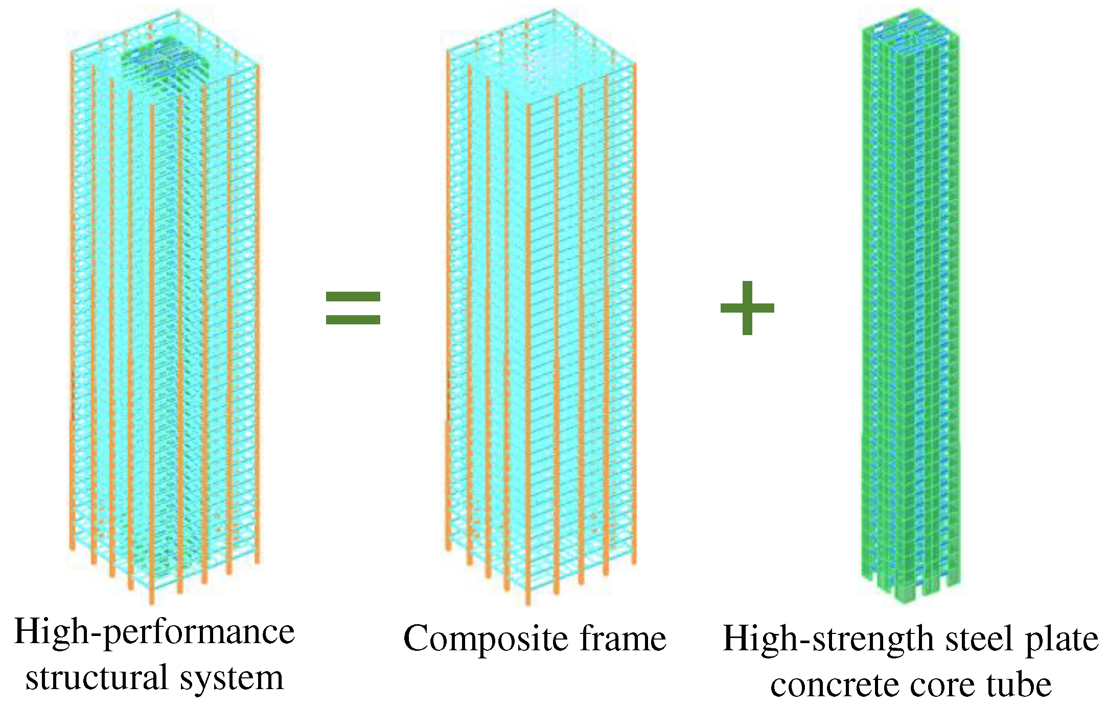
The high-performance structural system proposed by the paper mainly includes a composite frame and a high-strength steel plate concrete core tube (
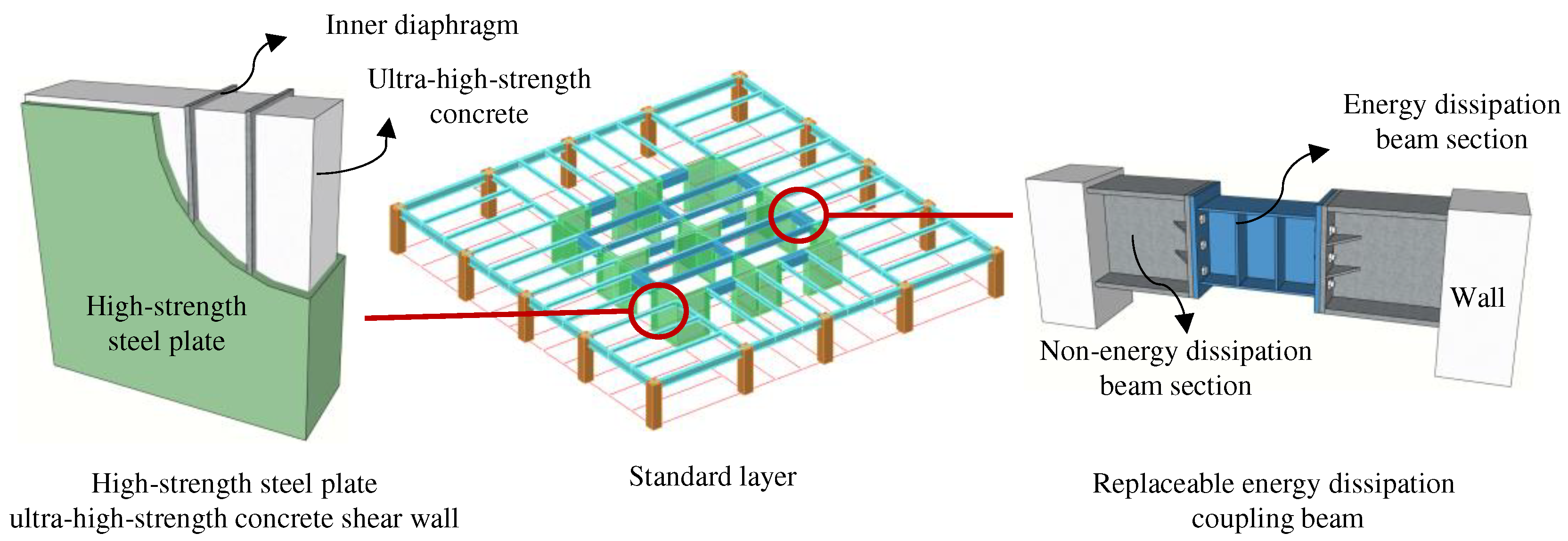
Figure 1); Among them, the high-strength steel plate concrete core tube is composed of high-strength steel plate ultra-high-strength concrete shear walls and replaceable energy dissipation coupling beams (
Figure 2). The proposed system aims to achieve the following objectives:
(1) Under MCEs, the energy consumption of the structure is mainly concentrated in the frame beam and replaceable energy dissipation coupling beam. The main structure is undamaged, ensuring that the structure can achieve rapid repair after earthquakes and improve the overall seismic resilience of the structure.
(2) The high-performance structural system, composed of high-strength steel and high-strength concrete, effectively saves building materials and achieves the goal of energy conservation and emission reduction in green buildings.
(3) Compared to the frame core tube structure made of conventional strength materials, the high-performance structural system can save engineering costs and improve the overall structural construction economy.
2.2. Performance Objectives
The seismic performance objectives for various structural components are detailed in
Table 1. The overall performance objective can meet the requirements of structural seismic performance objective C defined in the Technical Specification for Concrete Structures of Tall Buildings (JGJ 3-2010) [
22] (hereinafter referred to as the Tall Buildings Design Code).
3. Analysis model
3.1. Basic design information
The research object is a frame core tube structure, with 7.5 fortification intensity (0.15g,g=9.8 m/s
2), site class II and design earthquake classification I specified in the Code for Seismic Design of Buildings (GB 50011-2010) [
23] (hereinafter referred to as the Seismic Design Code). The height of the structure is 198.4m, with a total of 46 stories and an aspect ratio of 4.4. The plane size of the outer frame is 45m × 45m, with a core tube plane size of 21m × 21m.
To study the seismic performance of a new high-performance structural system, based on the PKPM building structure design software and with
Table 1 as the seismic performance objective, a conventional frame core tube design model (referred to as the conventional model, denoted as BM-7.5-C-P) and a high-performance frame core tube design model (referred to as the high-performance model, denoted as HP-7.5-C-P) were established, respectively. The structural layout is shown in
Figure 3.
The outer frame columns of the above two models are both concrete-filled square steel tubular columns (CFSSTCs), and the outer frame beams and the connecting beams between the outer frame and the core tube are all H-shaped steel beams. The connection form between the outer frame beam and the outer frame column is rigid connection, and the connecting beam is hinged at both ends. The main difference between the two models is the core tube. The core tube of BM-7.5-C-P is composed of reinforced concrete shear walls and reinforced concrete coupling beams, while the core tube of HP-7.5-C-P is composed of high-strength steel plate ultra-high-strength concrete shear walls and replaceable energy dissipation coupling beams. The main material consumption of the two models is shown in
Table 2, and the total structural weight of the high-performance model is reduced by 17% compared to the conventional model. The cross-sectional dimensions and material information of the main structural components of the two models are shown in
Table 3 and
Table 4, respectively.
3.2. Main design results
The vibration mode-decomposition response spectrum method is used for elastic time history analysis, with a damping ratio of 4% for each vibration mode. The main calculation indexes of BM-7.5-C-P and HP-7.5-C-P are shown in
Table 5. For tall concrete structures, the Tall Buildings Design Code stipulates that for tall buildings with heights between 150m and 250m, the elastic story drift ratio limit is interpolated between 1/800-1/500, and the limit value of the 198.4m model is 1/620; For structural systems composed of CFSSTCs, steel beams or composite beams, and concrete-filled steel plate shear walls (CFSPSWs), the General Composite Code for Composite Structures (GB55004-2021) [
24] (hereinafter referred to as the General Composite Code) stipulates that the elastic story drift ratio limit shall be taken according to the regulations of steel structures and shall not exceed 1/250. In summary, the design results of each structural model meet the requirements of China's structural design specifications.
3.3. Establishment and Verification of Elastoplastic Model
Establish SSG models for BM-7.5-C-P and HP-7.5-C-P, denoted as BM-7.5-C-S and HP-7.5-C-S, respectively. In the elastoplastic analysis of this paper, mode damping is used, and the damping ratio of each mode in the elastic stage of the structure is 4%. When the structure enters plasticity, damping is reflected through the nonlinear behavior of the material. Shear walls, reinforced concrete coupling beams, and slabs use elastoplastic layered shell elements, while columns, reinforced concrete beams, and H-shaped steel beams use fiber bundle Timoshenko beam elements. The constitutive model of concrete adopts an elastoplastic damage model, which can consider the differences in tensile and compressive strength of concrete materials, stiffness and strength degradation, as well as the stiffness recovery presented by the closure of tensile and compressive cyclic cracks; The nonlinear material model of steel adopts a bilinear kinematic hardening model.
Perform modal analysis on the structure and compare the main calculation indexes with PKPM results. For both types of structures, the total mass (representative value of gravity load) and the error between the first six periods calculated by the SSG model and the PKPM model are controlled within 3%, indicating that the SSG model is reasonable and accurate, and can be used for subsequent calculation and analysis.
3.4. Establishment and Verification of Elastoplastic Model
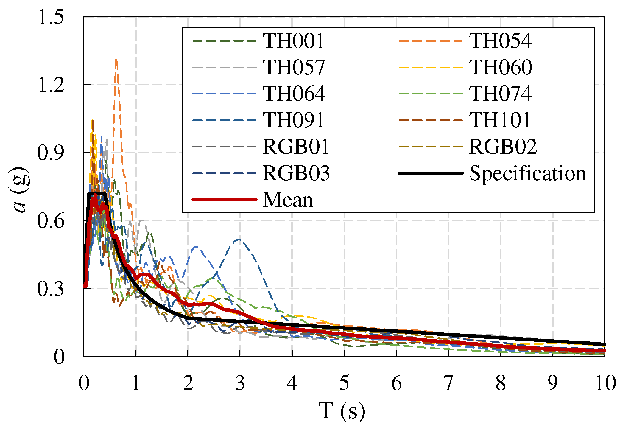
This paper focuses more on the elastoplastic situation of structures during MCEs. Therefore, an elastic model is used for ground motion selection, with a damping ratio of 5% equivalent to the level of MCEs. In theory, the damping ratio closed to the elastoplastic damping ratio of MCEs is the best. Based on the design earthquake and site classes of the research object, 8 sets of natural waves were selected from the strong earthquake record database, and 3 sets of artificial waves were generated. A total of 11 sets of ground motion records were used as seismic inputs, with each set of seismic waves containing two horizontal components and one vertical component. The number of seismic motions selected in this paper meets the requirements of 7 sets in the Seismic Design Code, and also meets the requirements of 11 sets in the Resilience Standard for the seismic resilience assessment of structures.
The ratio of the base shear force calculated by elastic time history analysis to the calculated results by mode-decomposition response spectrum method under each group of seismic input of the two models ranges from 0.76 to 1.21; The ratio of the average value of the base shear force input to the response spectrum for 11 sets of ground motion records is 99% for BM-7.5-C-P and 97% for HP-7.5-C-P, which meets the requirements of Article 5.1.2 (3) of the Seismic Design Code. The comparison between the main direction acceleration response spectrum and its average response spectrum of each group of ground motion records and the standard design response spectrum is shown in
Figure 4.
4. Elastoplastic analysis under MCEs
The seismic input for the elastoplastic analysis under MCEs in this paper is a three-dimensional input. The ratio of peak ground acceleration (PGA) in three directions is 1:0.85:0.65 (main direction: secondary direction: vertical), and the PGA of the main direction is 0.31g. The specific analysis results are as follows.
4.1. Story displacement and story drift ratio
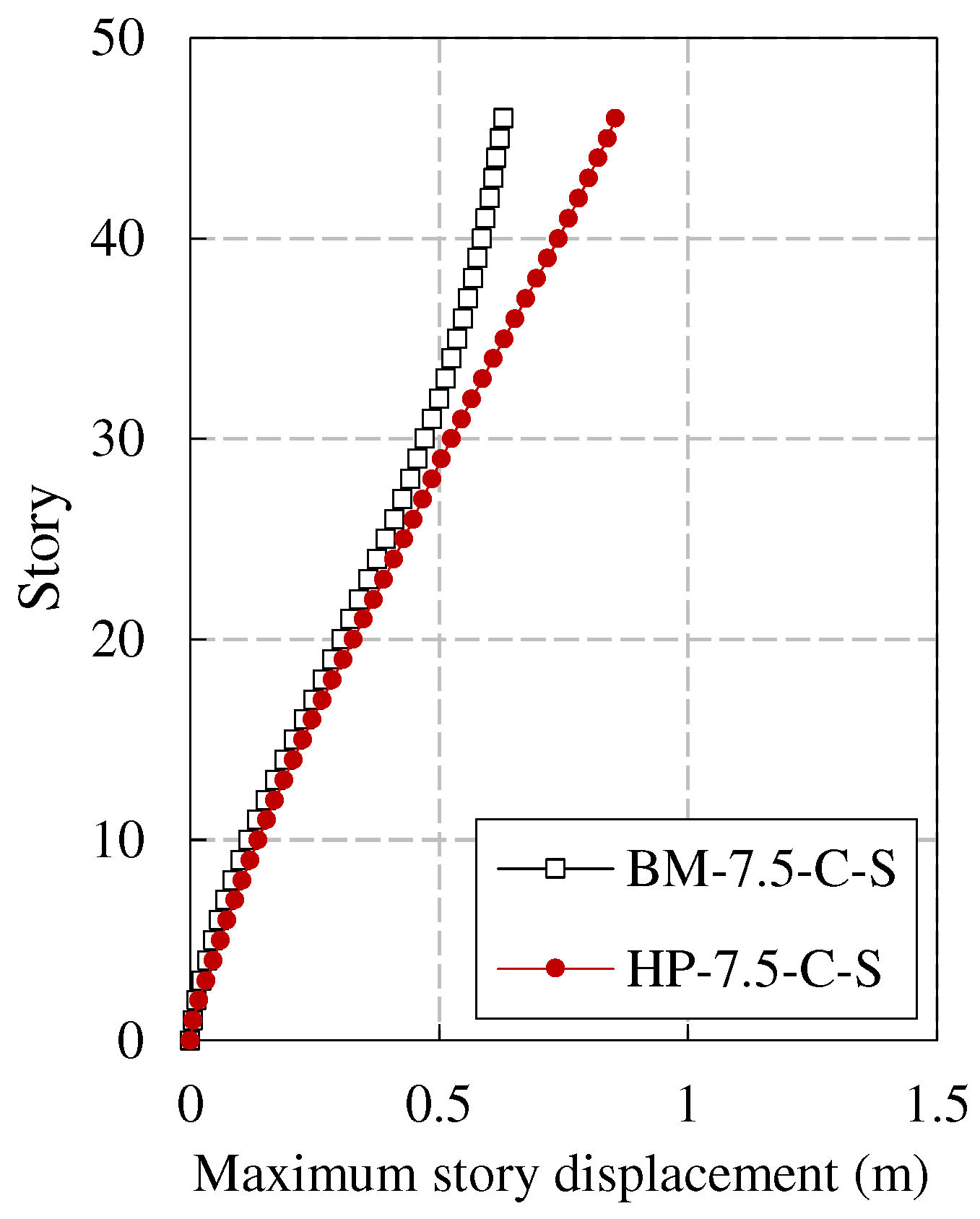
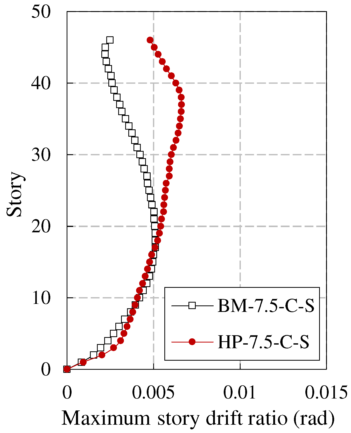
The average values of the story displacement envelope and story drift ratio envelope of the two models (BM-7.5-C-S and HP-7.5-C-S) under the input ground motions are shown in
Figure 5 and
Figure 6, respectively. It can be observed that the story displacement and story drift ratio responses in the lower part of the two models are relatively close; In the middle upper part, the story displacement and story drift ratio of BM-7.5-C-S are smaller than those of HP-7.5-C-S.
According to the Seismic Design Code and the General Composite Code, the story drift ratio limit of BM-7.5-C-S under MCEs is 1/100; The story drift ratio limit of HP-7.5-C-S is 1/50. From the analysis results, it can be seen that the story drift ratio of the two models under MCEs meets the specification requirements. The ratios of the plastic story drift ratio limits corresponding to BM-7.5-C-S and HP-7.5-C-S to their corresponding maximum story drift ratios are 2.0 and 3.0, respectively. It can be seen that under MCEs, the story drift ratio of HP-7.5-C-S has higher redundancy than that of BM-7.5-C-S compared to the specification limits. In summary, the new high-performance structural system performs better in evaluating the story drift ratio under MCEs.
4.2. Development of Structural Plasticity
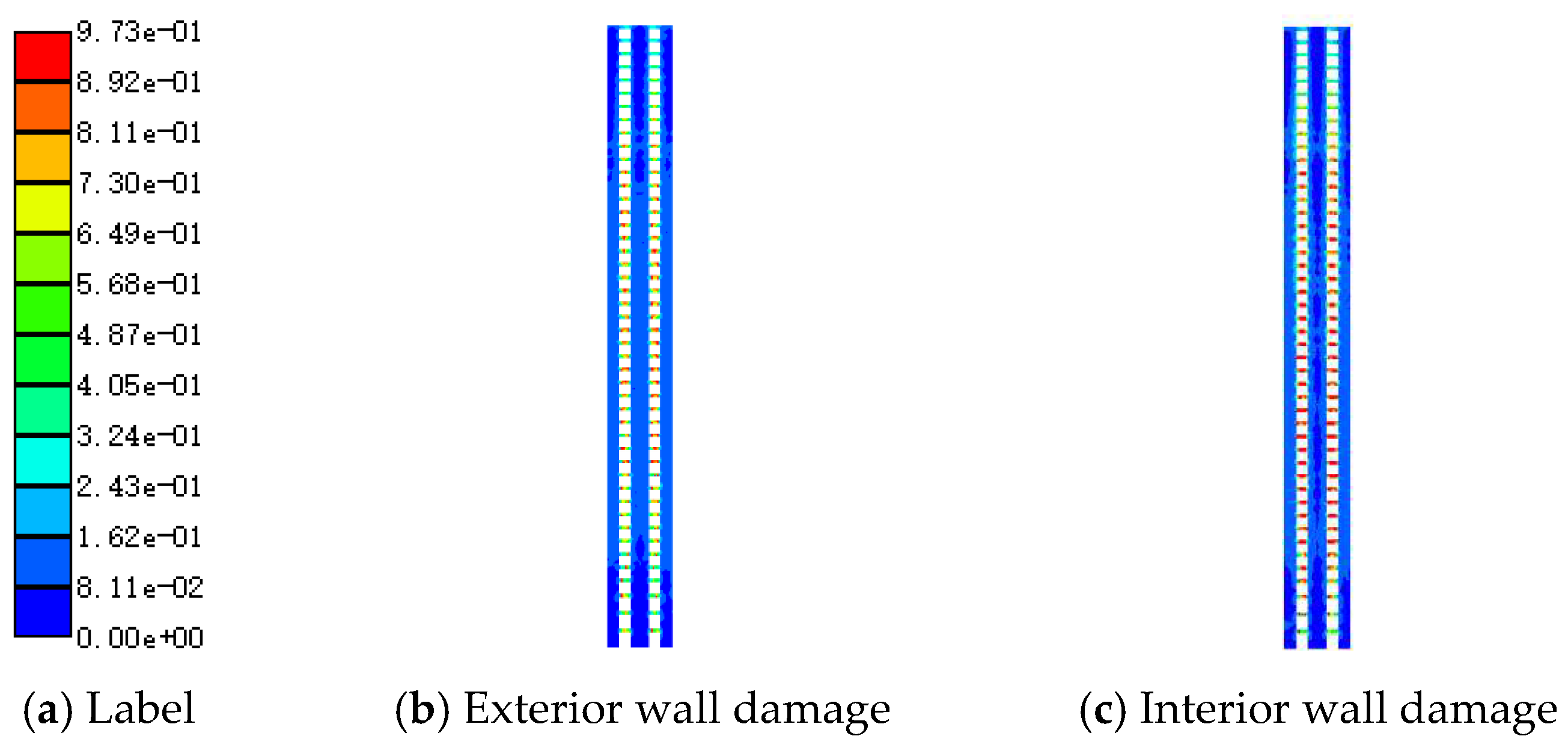
There are certain differences in the damage of the structure under different seismic inputs. According to the finite element analysis results, the plastic development of the two models is more significant under the action of natural wave TH054. Therefore, taking the TH054 earthquake condition as an example, the plastic development of the core tube and outer frame of the two models under MCEs is introduced. The plastic development of the core tube of BM-7.5-C-S and HP-7.5-C-S is shown in
Figure 7 and
Figure 8, respectively. For concrete components in the figure, the label represents the compressive damage factor; For steel components, the label represents the ratio of the maximum stress to yield stress of the component. The steel of the outer frame of both models has not entered plasticity, and the concrete compression damage factor is within 0.1. The outer frame is basically intact, and will not be repeated in the following text.
The majority of shear walls in BM-7.5-C-S have a compressive damage factor of less than 0.1, and the components are basically intact; More than 50% of the coupling beams have a compression damage factor exceeding 0.3, which plays a role in energy dissipation and vibration reduction. The majority of HP-7.5-C-S shear wall concrete is undamaged, and the stress level of the steel plate is relatively low, which can be controlled within 30% of the yield stress. The components are basically intact; The non-energy dissipation beam section of the replaceable energy dissipation coupling beam is in an elastic working state, meeting the design requirements. The energy dissipation beam section can achieve energy consumption, and the hysteresis curve under earthquakes is full.
4.3. Structural stiffness degradation
As the seismic response increases, the structure gradually enters plasticity, the overall stiffness deteriorates, and the period extends. Therefore, after the elastoplastic time history analysis of the structure, the mode analysis can be performed to quantitatively evaluate the stiffness degradation of the structure through the extension of the fundamental period of the structure. According to the relationship between period and stiffness, the degradation rate
DKi of a certain order of stiffness can be calculated by the following equation:
In the formula, Ti is the i-th order period of the structure before earthquake, and Ti’ is the i-th order period of the structure after earthquake.
The first-order stiffness degradation rates of the two models after 11 sets of ground motion records are shown in
Table 6. The average stiffness degradation rates of BM-7.5-C-S and HP-7.5-C-S are 0.09 and 0.02, respectively. It can be observed that the stiffness degradation of the high-performance structural system is significantly smaller than that of conventional structural systems, indicating that the high-performance structural system has better seismic performance.
4.4. Assessment of the function of the second line of defense of the outer frame
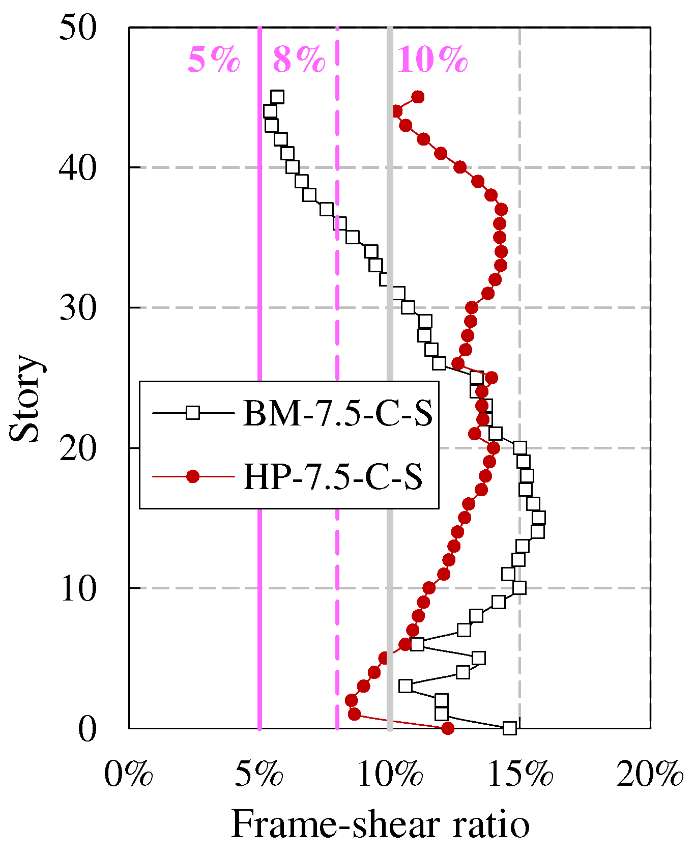
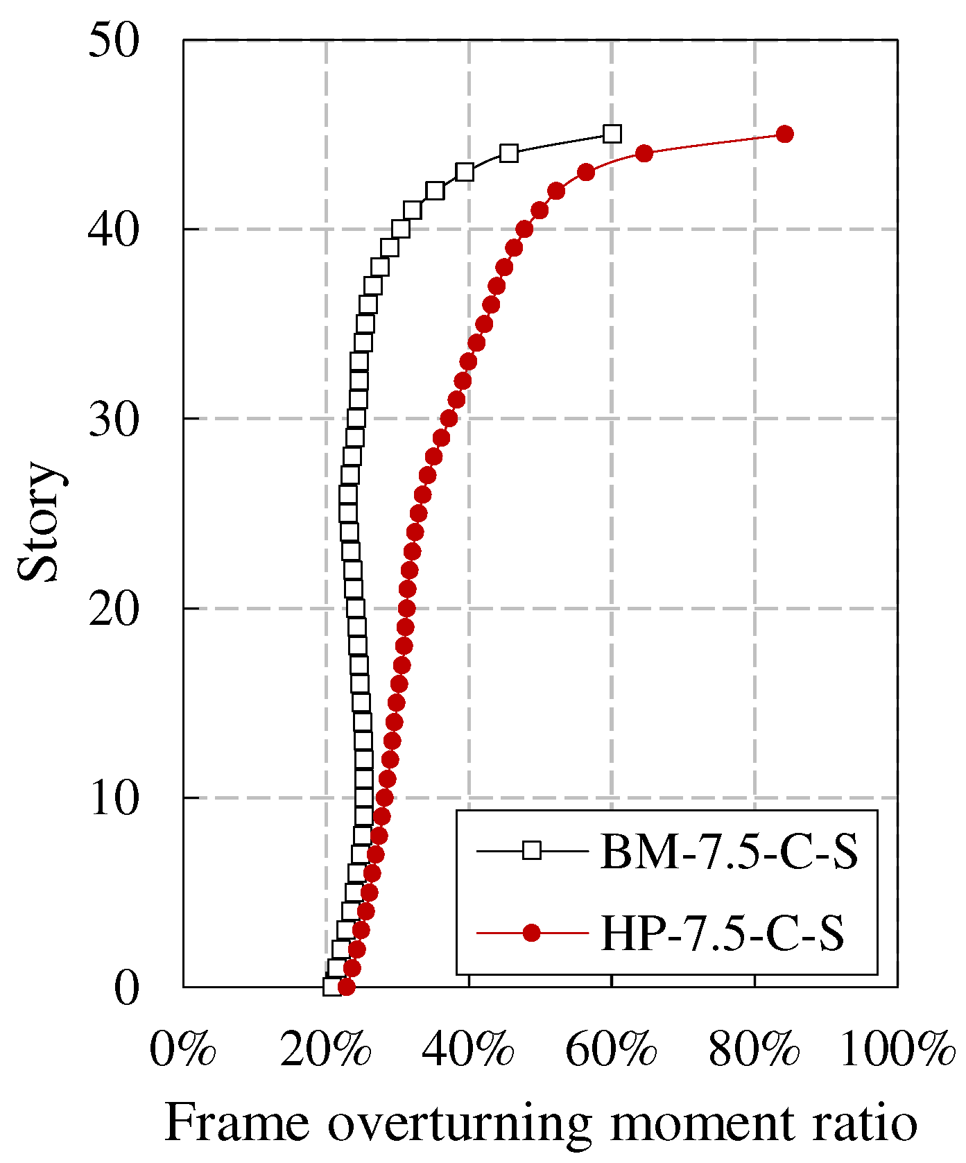
For frame core tube super tall buildings, under strong earthquake, the core tube, as the first line of defense, may suffer serious damage. After internal force redistribution, the outer frame will bear a significant seismic effect. Therefore, there should be an appropriate proportion of stiffness between the core tube and the outer frame to play the role of the second line of defense of the outer frame. The effect of the second line of defense can be evaluated by the frame-shear ratio (frame layer shear force/base shear force) and the frame overturning moment ratio (frame overturning moment/total overturning moment). The calculation results are shown in
Figure 9 and
Figure 10, respectively.
In the 2015 edition of the Technical Key Points for Special Review of Seismic Fortification of Tall Building Engineering (MOHURD, 2015) (hereinafter referred to as the Technical Key Points), it is stipulated that the story shear force allocated by the outer frame, except for individual stories at the bottom, strengthened stories and theirs upper and lower stories, is not less than 8% of the base shear force, and the maximum value should not be less than 10%, and the minimum value should not be less than 5%. The maximum frame-shear ratio of both models is greater than 10%, and the minimum value is greater than 5%; The proportion of stories with frame-shear ratio greater than 8% for BM-7.5-C-S and HP-7.5-C-S is 80.4% and 100%, respectively. In summary, the frame-shear ratio of each model meets the requirements of the Technical Key Points, and HP-7.5-C-S has better performance.
The frame overturning moment ratio of the bottom frame under MCEs for BM-7.5-C-S and HP-7.5-C-S is 20.9% and 22.9%, respectively, which is increased by 30.3% and 1.0% compared to the results under SLEs. The results indicate that the function of the second line of defense of the new high-performance structural system is slightly stronger than that of the conventional structural system. At the same time, with the development of structural plasticity, the function of the second line of defense is also increasing, reflecting the advantages of the dual system. It is worth noting that the bottom frame overturning moment ratio of the HP-7.5-C-S has only increased by 1%, which to some extent indicates that the plastic damage of the core tube and the overall stiffness degradation of the structure are relatively small under MCEs. This conclusion can be mutually confirmed with the analysis results in sections 4.2 and 4.3.
5. Seismic resilience assessment
5.1. Assessment process
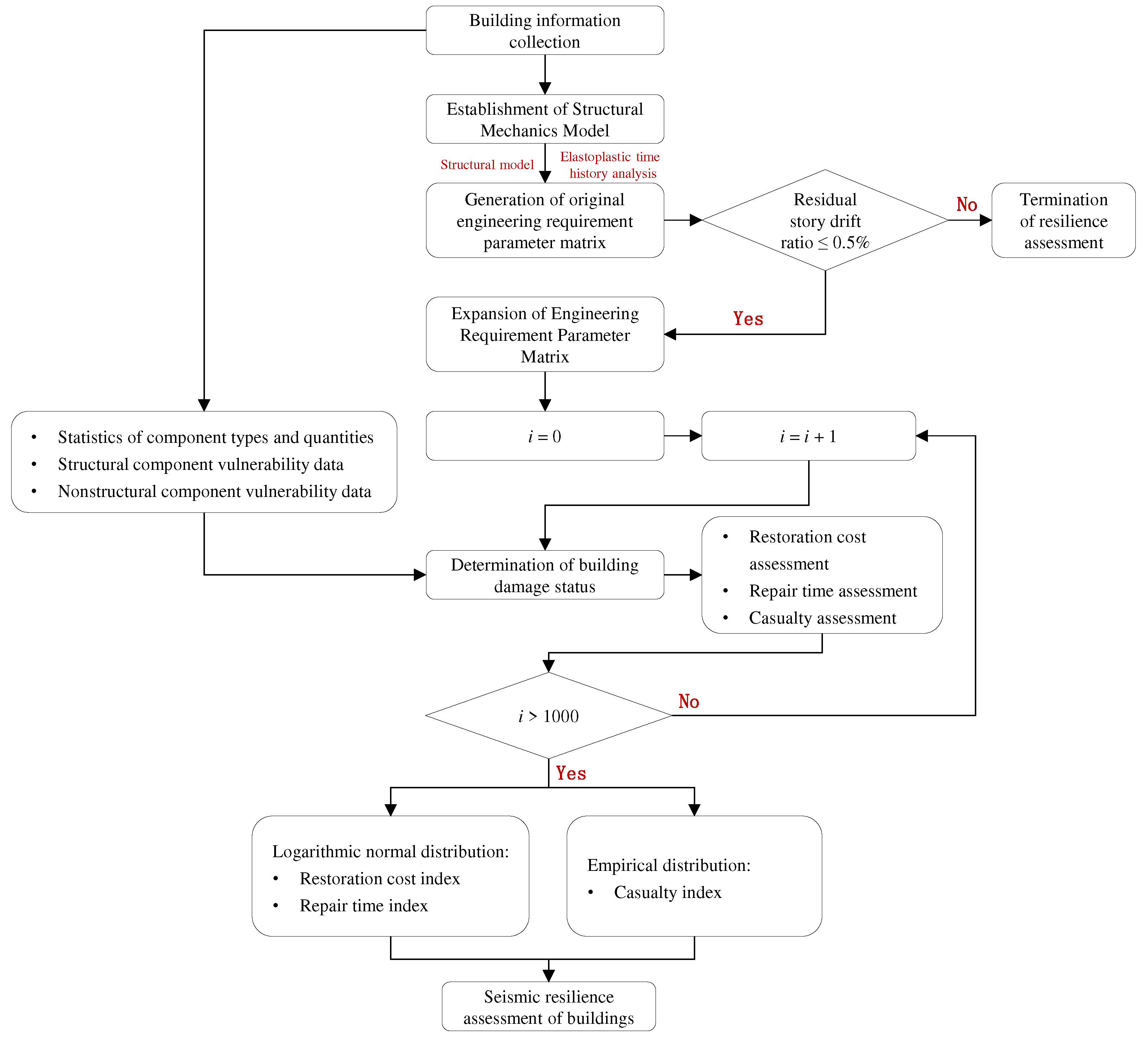
Based on the Resilience Standard and using the seismic resilience assessment program developed by the research group as a tool (Cui, 2022), the seismic resilience assessment of various structural models is carried out. The specific assessment process is shown in
Figure 11.
For a given structural model, first, determine the basic information of buildings and its components (type, quantity, and vulnerability data), and select no less than 11 sets of ground motion records according to the design earthquake and site classes; Then, elastoplastic time history analysis of the structural model is carried out, and the seismic input adopts a three-dimensional input to form the original engineering demand parameter matrix. When the average value of the residual story drift ratio envelope meets the 0.5% limit specified in the Resilience Standard, the seismic resilience assessment of buildings can be carried out.
To enhance the robustness of the assessment results, Monte Carlo simulation method is used to expand the engineering demand parameter matrix, so that the expanded engineering demand parameters have the same joint distribution and probability distribution parameters as the original engineering demand parameter matrix; In a Monte Carlo simulation, the damage state of components is determined by generating random numbers, combined with the exceeding probability of various damage states of the components, and the seismic resilience assessment index of buildings (restoration cost, repair time, and casualty) can be calculated. The Resilience Standard stipulates that the number of simulations should not be less than 1000. The seismic resilience assessment index adopts the fitting values with an 84% guarantee rate calculated by Monte Carlo simulation method. Among them, the restoration cost index and repair time index are fitted using the logarithmic normal distribution model recommended by the Resilience Standard. While the distribution of casualty index does not conform to the logarithmic normal distribution [
25], therefore, an empirical distribution model is used for fitting.
Finally, the seismic resilience assessment level of buildings should be comprehensively evaluated based on the three seismic resilience assessment indexes, and the lowest level of the three indexes should be taken as the seismic resilience assessment level of buildings.
The determination of the seismic resilience assessment level of buildings is divided into two stages [
26]: (1) In the first stage, the seismic resilience assessment of buildings under DBEs should be carried out. If it meets the requirements of one-star resilient buildings, the next stage assessment can be carried out; otherwise, the assessment will be terminated; (2) In the second stage, seismic resilience assessment of buildings under MCEs will be carried out. If it meets the requirements of two-star or three-star buildings, the seismic resilience assessment level will be updated. Otherwise, the judgment results of the original one-star resilient building will be maintained.
5.2. Value of vulnerability parameters for composite components.
The structural models for seismic resilience comparison in this section include CFSSTCs, CFSPSWs, and steel reinforced concrete shear walls. The recommended values for the vulnerability parameters of these components are not provided in the Resilience Standard. Among them, for steel reinforced concrete shear walls, Cui [
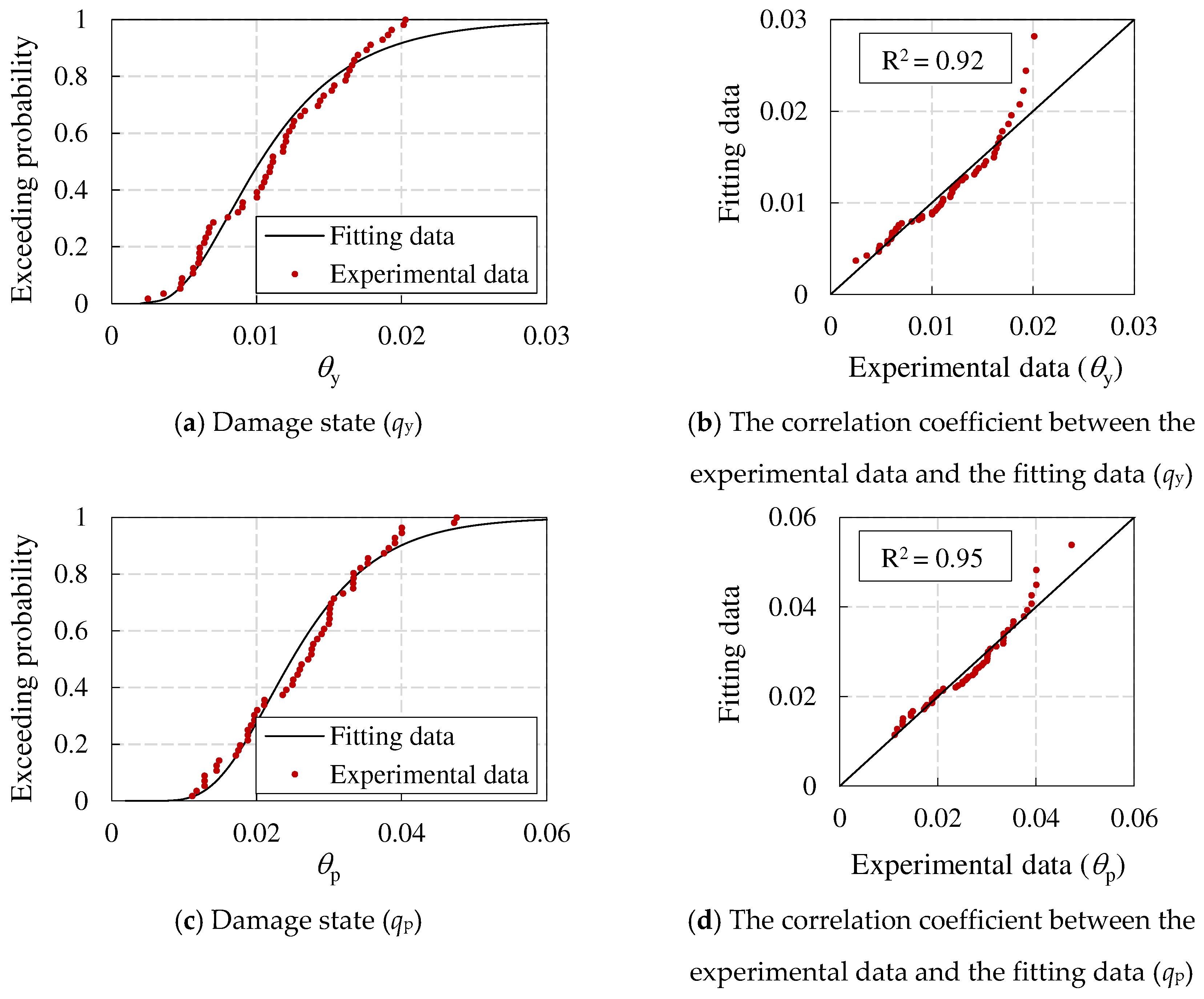
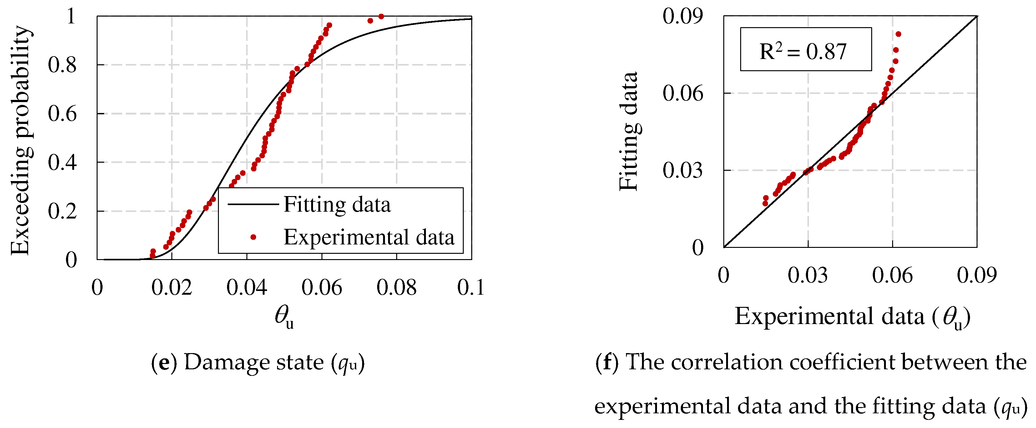
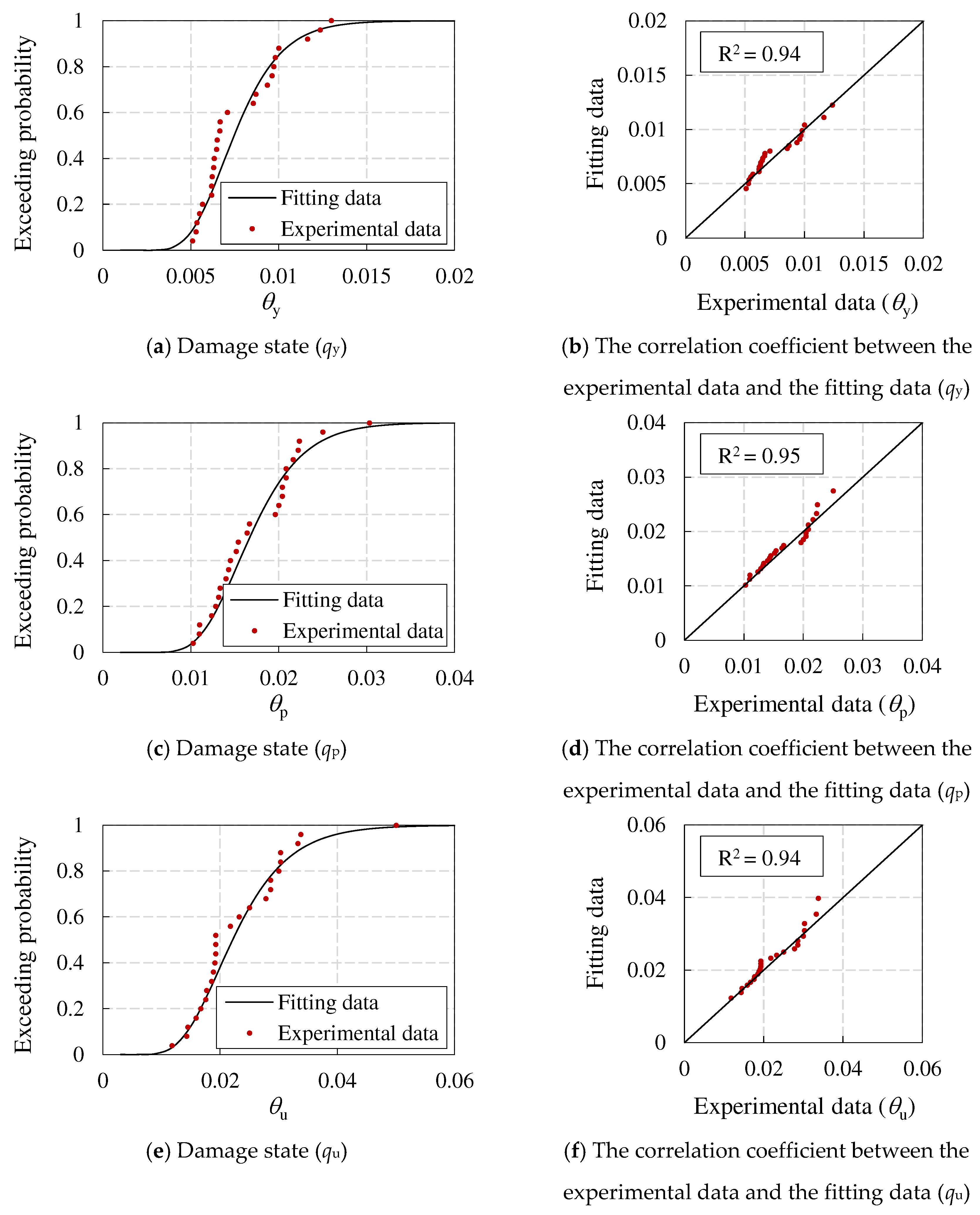
21] provided the suggested value that can be used for the seismic resilience assessment based on existing literature experimental data. Therefore, this paper adopts the suggested value as the vulnerability parameter of steel reinforced concrete shear walls. For CFSSTCs and CFSPSWs, there is no relevant literature to statistically organize the experimental data. Therefore, this paper calibrates the vulnerability parameters of CFSSTCs and CFSPSWs by collecting and organizing experimental data from existing literature. The specific steps are as follows:
(1) Based on experimental data in the literature, calculate the rotation angles of the components corresponding to the nominal yield point, peak point, and limit point, namely θy, θp, θu;
(2) Assuming that the experimental data conforms to a logarithmic normal distribution, calculate the logarithmic mean and logarithmic standard deviation of the experimental data under various rotation angles, and determine the corresponding logarithmic normal distribution function;
(3) Calculate the correlation coefficient R between the experimental data and the fitted data determined based on the logarithmic normal distribution. If R>0.8, it indicates a strong correlation between the experimental data and the fitted data, and the assumption of a logarithmic distribution is valid;
(4) Determine the median value and logarithmic standard deviation for each limit state of the component based on the characteristics of the logarithmic normal distribution.
This paper collected relevant literature and summarized the seismic experimental data of 56 CFSSTCs [
27,
28,
29,
30,
31,
32,
33,
34,
35] and 25 CFSPSWs [
11,
36,
37,
38,
39]. Then, statistical analysis was conducted on the
θy,
θp,
θu of CFSSTCs and CFSPSWs, respectively. The experimental data conforms to the logarithmic normal distribution, as shown in
Figure 12 and
Figure 13. The correlation coefficient between the experimental data and the fitting data of each limit rotation angle of various components is greater than 0.93, indicating that each group of experimental data conforms to the logarithmic normal distribution. The vulnerability parameters of CFSSTCs and CFSPSWs are shown in
Table 7.
5.3. Comparison of seismic resilience assessment results
This section conducted seismic resilience assessment for both conventional and high-performance models under DBEs and MCEs, and the assessment results (restoration cost index
κ, repair time index
Ttot, injury rate
γH, and death rate
γD) are shown in
Table 8. The specific conclusions are as follows:
(1) Under DBEs, seismic resilience assessment results of both models are one-star, and all indexes are superior to the assessment standards. Among them, the high-performance model has better indexes;
(2) Under MCEs, seismic resilience assessment results of both models are two-star; The restoration cost index of both models can reach a three-star rating, and the repair time index can reach a two-star rating, while the high-performance model have better indexes; There is a significant difference in casualty index between the two models. The high-performance model is rated as three-star, while the conventional model is rated as two-star;
(3) The conventional model already has good seismic resilience. For high-performance models, the entire core tube adopts high-performance CFSPSWs and replaceable energy dissipation coupling beams, which have better seismic resilience assessment indexes under DBEs and MCEs. The restoration cost index, repair time index, injury rate, and death rate under MCEs of the high-performance model are 62.2%, 84.7%, 4.9%, and 0% of those of the conventional model, respectively. Therefore, high-performance models can better ensure the safety of people’s lives and property.
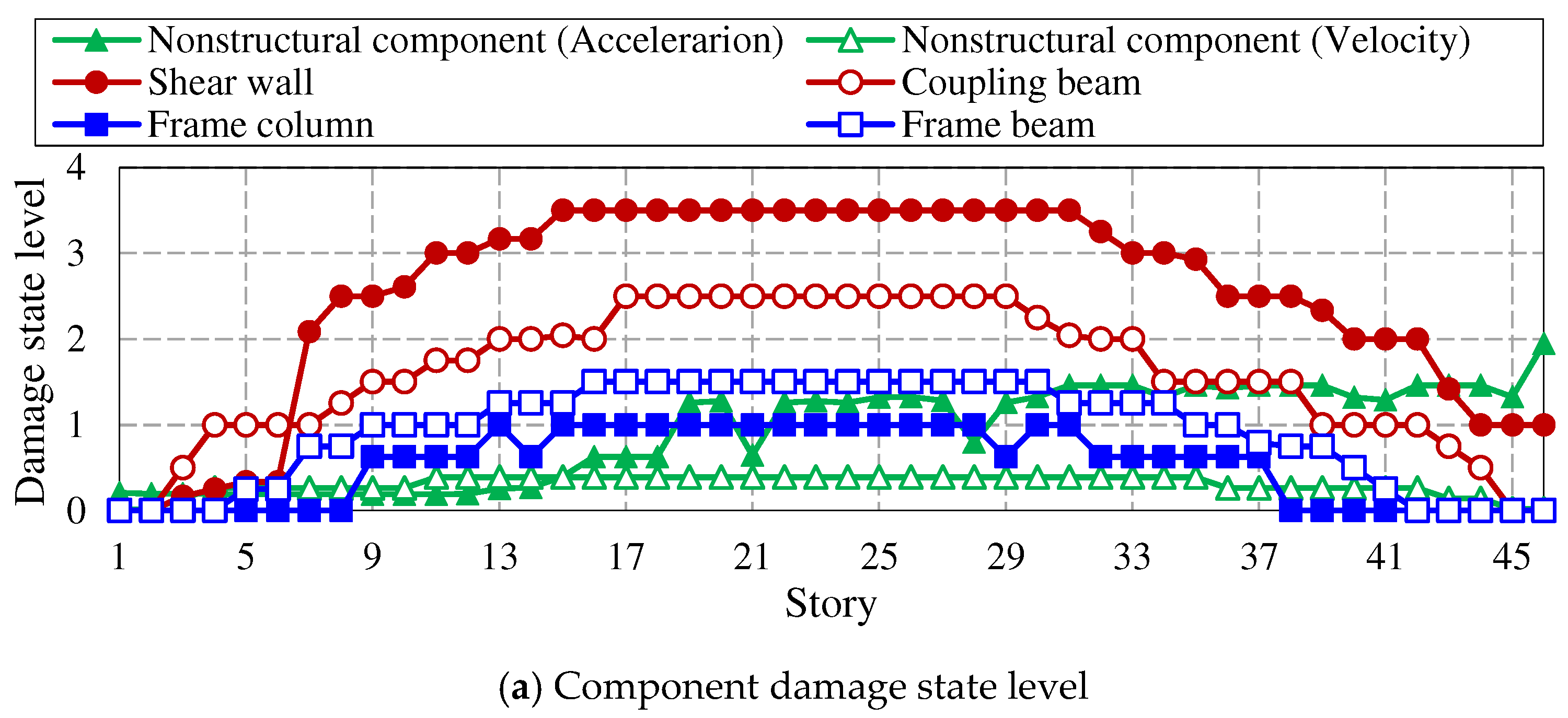
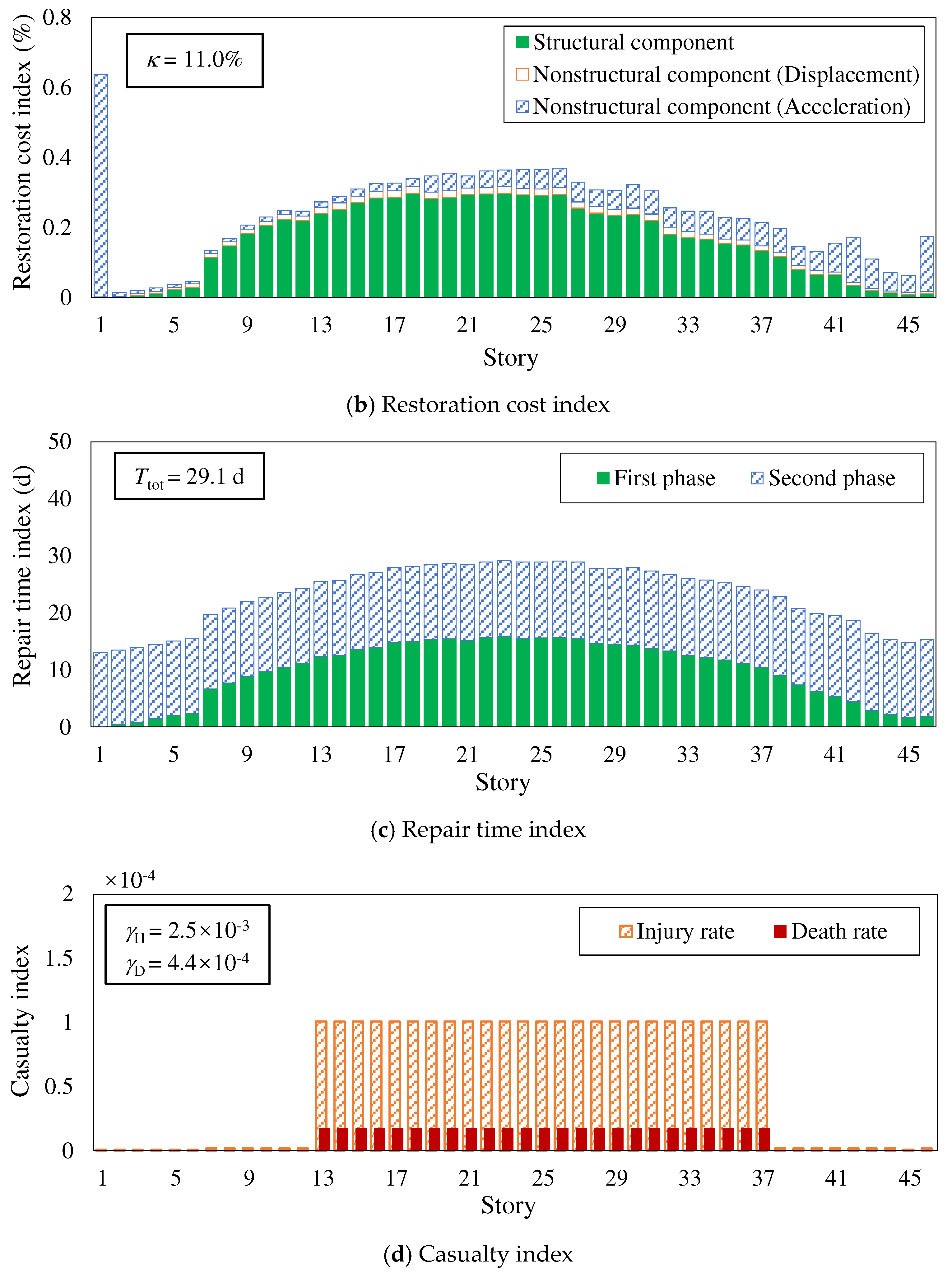
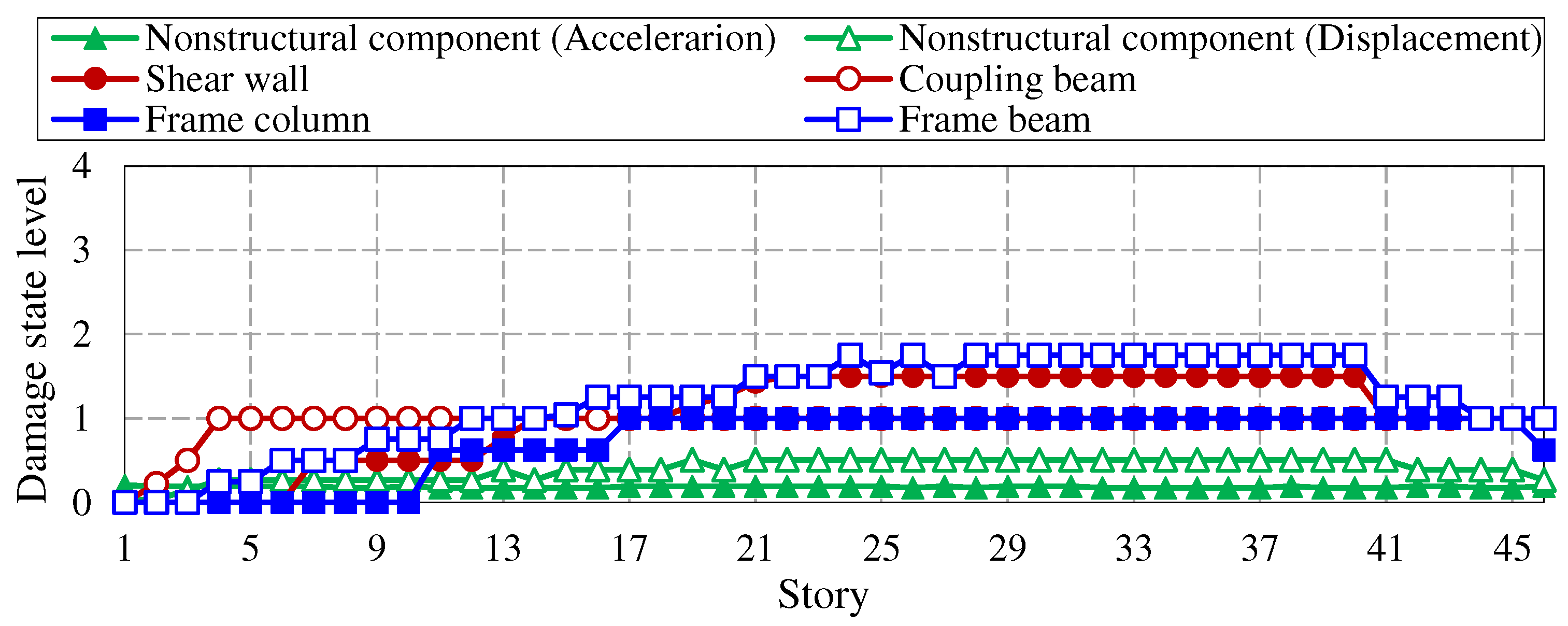
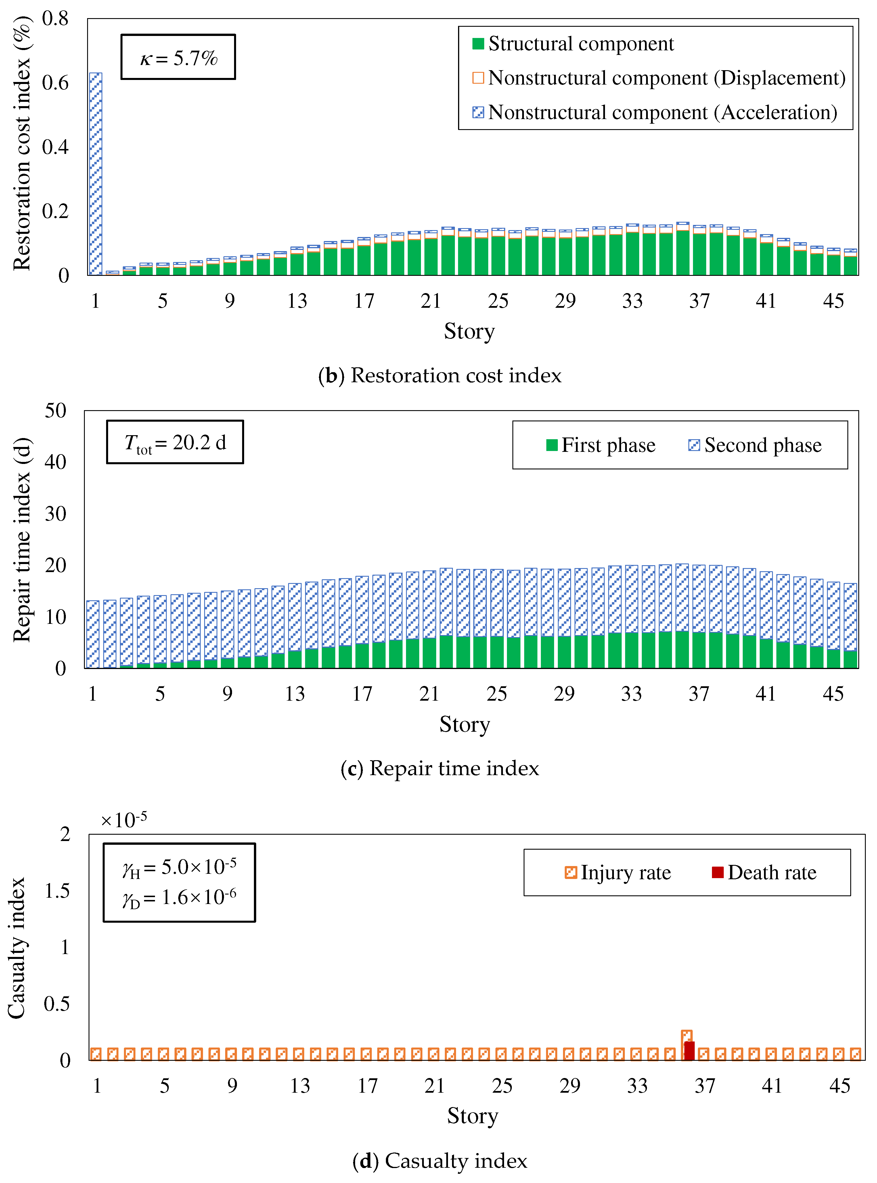
At present, the impact of EREs on building structures is not considered in China’s seismic fortification system. However, due to the complexity and uncertainty of earthquakes, there is a possibility of buildings being subjected to EREs during the design reference period, such as the Tangshan earthquake in 1976, when the fortification intensity of Tangshan was 6 degrees (currently 8 degrees) and the actual intensity of the epicenter reached 11 degrees; The 2008 Wenchuan earthquake had a fortification intensity of 7 degrees and the actual intensity of the epicenter reached 11 degrees. Therefore, it is necessary to study the seismic resilience of super tall buildings under EREs. This paper compares the seismic resilience assessment levels of two models under a ERE condition of 510gal, and the assessment results are shown in
Table 9. The component damage state level, restoration cost, repair time, injury rate and death rate of each story of each model are shown in
Figure 14 and
Figure 15. Among them, the component damage state level is evaluated based on the percentile value with an 84% guarantee rate obtained from 1000 Monte Carlo simulation results. The specific conclusions are as follows:
(1) According to the story distribution diagram of component damage state levels, under EREs, the damage of the conventional model is mainly concentrated in the central core tube, the damage state levels of shear walls and coupling beams are greater than level 3 and level 2, respectively, as shown in
Figure 14 (a); The overall damage of the high-performance model is relatively small, and the damage state level of each component is less than level 2, as shown in
Figure 15 (a);
(2) Under EREs, the final seismic resilience assessment result of the conventional model is zero-star, while that of the high-performance model is two-star. Among them, the repair time index of the conventional model is two-star, while other indexes are zero-star. The restoration cost index and repair time index of the high-performance model are two-star, and the casualty index is three-star, as shown in
Table 9; The restoration cost index, repair time index, injury rate, and death rate of the high-performance model are 51.8%, 69.4%, 2.0%, and 0.4% of those of the conventional model, respectively.
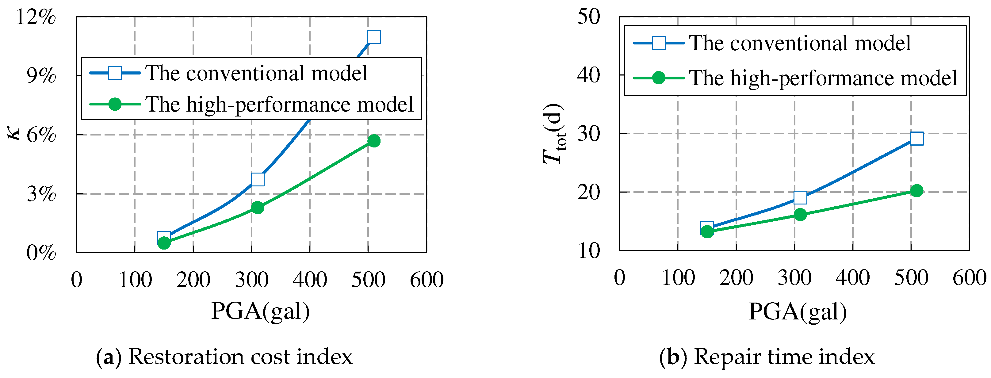
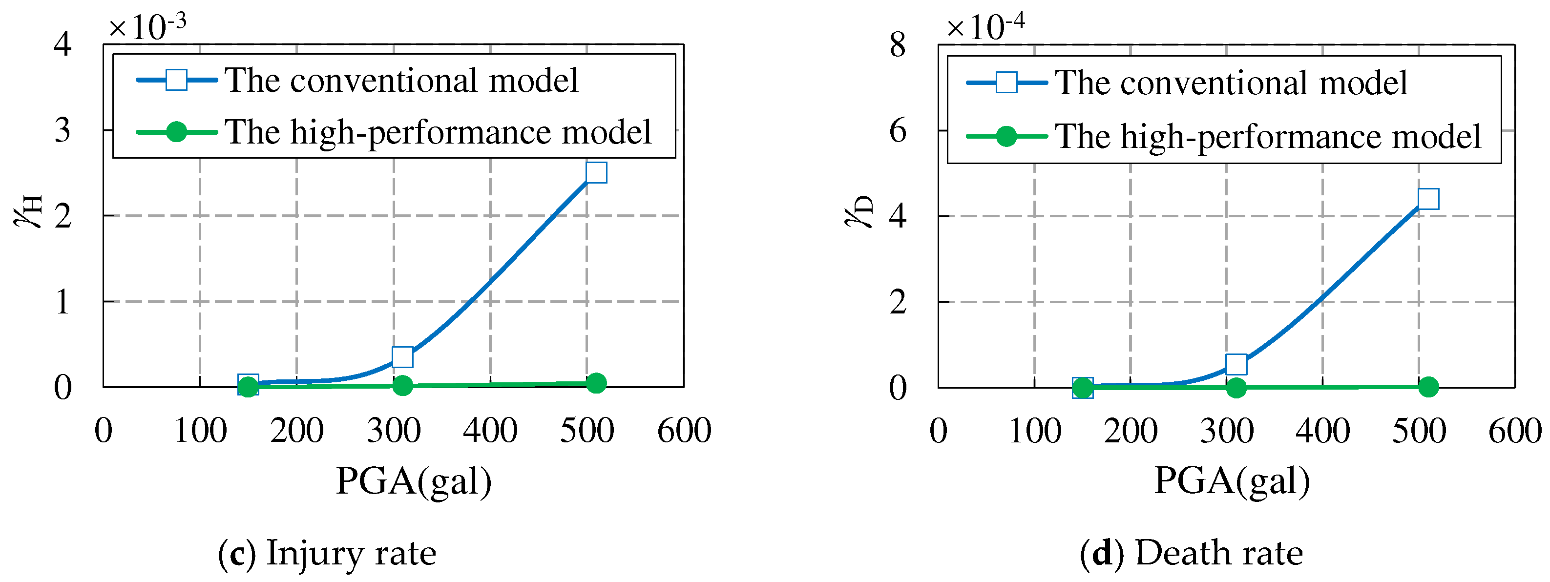
In summary, the high-performance model has the best seismic resilience under various earthquake conditions. At the same time, as the earthquake intensity increases, the seismic resilience of the high-performance model significantly improves, especially in terms of casualties, as shown in
Figure 16.
6. Conclusion
This paper proposes a composite frame - high-strength steel plate wall core tube resilient structure system, and designs two 200m level frame core tube models, which are the conventional model and the high-performance model. Corresponding elastoplastic analysis models are established to compare the seismic performance of each model under MCEs, as well as the seismic resilience under DBEs, MCEs, and EREs. The effectiveness of the proposed new high-performance structural system has been verified. The main conclusions of this paper are as follows:
(1) Compared to the conventional model, the high-performance model can effectively reduce the size of shear walls, reduce the self-weight of structures, and enhance the space for building use; The overall stiffness of the structure has decreased and the period has increased, but it is still within a reasonable range and meets the design requirements.
(2) Under MCEs, compared to the conventional model, the high-performance model has higher redundancy in terms of the story drift ratio, lower plastic damage and overall stiffness degradation of the structure, and better seismic performance; In addition, the frame-shear ratio of both models meets the requirements of the Technical Key Points, and the high-performance model performs better. At the same time, the bottom frame overturning moment ratio of both models exceeds 20%, and the outer frame can achieve the function of the second line of defense.
(3) This paper calibrates the vulnerability parameters of CFSSTCs and CFSPSWs by collecting and organizing experimental data from existing literature, providing basic data for the seismic resilience assessment of new high-performance structural systems.
(4) The seismic resilience assessment level of both conventional and high-performance models is two-star, but the assessment indexes of the high-performance model are better than those of the conventional model; Under EREs, the seismic resilience assessment level of the high-performance model is still two-star, while the conventional model is zero-star. The seismic resilience of the high-performance model is optimal under various earthquake conditions. At the same time, as the earthquake intensity increases, compared to the conventional model, the seismic resilience of the high-performance model significantly improves, especially in the case of casualties, which can better ensure the safety of people's lives and property.
Author Contributions
Writing – original draft, Lei Zhang; Writing – review & editing, Cuikun Wang, Caihua Chen and Mingzhe Cui.
Funding
In this paper, the research was sponsored by the National Key Research and Development Program of China (Grant No. 2022YFC3802000).
Data Availability Statement
Data presented in this research is available on request from the corresponding author.
Conflicts of Interest
The authors declare no conflict of interest.
References
- FEMA. NEHRP Guidelines and Commentary for Seismic Rehabilitation of Buildings: FEMA 273. Federal Emergency Management Agency: Washington, DC, 1997.
- FEMA. Prestandard and Commentary for the Seismic Rehabilitation of Buildings: FEMA 356. Federal Emergency Management Agency: Washington, DC, 2000.
- FEMA. Next-generation Performance-Based Seismic Design Guidelines: FEMA 445. Federal Emergency Management Agency: Washington, DC, 2007.
- FEMA. Seismic Performance Assessment of Buildings Volume 1-Methodology, FEMA-P58. Federal Emergency Management Agency: Washington, DC, 2012.
- PEER. Guidelines for Performance-Based Seismic Design of Tall Buildings. Berkeley: University of California, 2010.
- Wang, B.; Jiang, H.; Lu, X. Seismic Performance of Steel Plate Reinforced Concrete Shear Wall and Its Application in China Mainland. J. Constr. Steel Res. 2017, 131, 132-143. [CrossRef]
- Fan, J.; Ding, R.; Nie, X.; Guo, L.; Yan, J. Research and Application of High-Performance Double Steel-Plate Reinforced Concrete Structures. J. Build. Struct. 2022, 43, 55-72.
- Cao, W.; Yu, C.; Dong, H.; Qiao, Q.; Han, L.; Zhang, Y. Experimental Study on Seismic Performance of Composite Shear Walls with Double Steel Plates Under Different Constructions. J. Build. Struct. 2013, 34, 186-191.
- Chen, L.; Yin, C.; Wang, C.; Liu, Y. Experimental Study on Seismic Behavior of Double-Skin Composite Wall With L-Shaped Connectors. J. Constr. Steel Res. 2020, 174, 106312. [CrossRef]
- He, W.; Wan, Y.; Li, Y.; Bu, J.; Deng, J.; Chen, L.; Zhang, W.; Wen, L. Experimental Study on Seismic Behaviors of The Welded L-Shaped Double Steel Plate-Concrete Composite Shear Wall. J. Constr. Steel Res. 2021, 187, 106944. [CrossRef]
- Liu, D.; Shi, Y.; Yu, X. Experimental Study on Seismic Behavior of Modular Composite Shear Wall with Double Steel Plates and Infill Concrete. Eng. Mech. 2022, 39, 250-260.
- Wang, K.; Zhang, W.; Chen, Y.; Ding, Y. Seismic Analysis and Design of Composite Shear Wall with Stiffened Steel Plate and Infilled Concrete. Materials 2022, 15, 182-214. [CrossRef]
- Ministry of Housing and Urban-Rural Development of the People's Republic of China (MOHURD). Technical Key Points for Special Review of Seismic Fortification of Tall Building Engineering. 2015. Available online: https://www.mohurd.gov.cn/gongkai/zhengce/zhengcefilelib/201505/20150528_220992.html (accessed on 21 May 2015).
- Ministry of Housing and Urban-Rural Development of the People's Republic of China (MOHURD). Technical Standard for Steel Plate Concrete Structures of Nuclear Power Plants GB/T 51340-2018. China Planning Press: Beijing, China, 2018.
- Liu, H. Research on the Application of Steel Plate Shear Wall Construction Technology in The Construction of a Super High-Rise Building. Shanxi Archit. 2020, 46, 77-79.
- Mao, Z.; Ding, M.; Chen, Z. Structural Design of Steel Frame-Composite Steel Plate Shear Wall in a High-Rise Residential Building. Build. Struct. 2020, 50, 88-91.
- Dong, C.; Guo, Q.; Wang, S.; Li, F. Construction Technology of Core Combination Steel Shear Wall in Super High-rise Building Project. Struct. Constr. 2021, 43, 37-39.
- Xiao, C.; Li, J.; Lu, Y.; Li, Y. Research on Seismic Performance of Frame-Core Tube Energy Dissipation Structure with C100 High-Strength Concrete. J. Build. Struct. 2021, 42, 1-9.
- Jiang, D.; Xiao, C.; Chen, T.; Zhang, Y. Experimental Study of High-Strength Concrete-Steel Plate Composite Shear Walls. Appl. Sci. 2019, 9, 2820. [CrossRef]
- Ministry of Housing and Urban-Rural Development of the People's Republic of China (MOHURD). Standard for seismic Resilience Assessment of Buildings GB/T 38591-2020. China Quality Inspection Press: Beijing, China, 2020.
- Cui, M. Research on Seismic Performance Evaluation Method of Existing High-Rise Buildings. Doctor’s Thesis, China Academy of Building Research: Beijing, China, 2022.
- Ministry of Housing and Urban-Rural Development of the People's Republic of China (MOHURD). Technical Specification for Concrete Structures of Tall Building JGJ 3-2010. China Architecture & Building Press: Beijing, China, 2010.
- Ministry of Housing and Urban-Rural Development of the People's Republic of China (MOHURD). Code for Seismic Design of Buildings GB 50011-2010. China Architecture & Building Press: Beijing, China, 2010.
- Ministry of Housing and Urban-Rural Development of the People's Republic of China (MOHURD). General Code for composite structures GB 55004-2021. China Architecture & Building Press: Beijing, China, 2021.
- Cui, M.; Wang, C.; Chen, C.; Pan, Y.; Xiong, Y.; Ren, C. Seismic Resilience Assessment of Existing High-Rise Shear Wall Structure Based on Standard for Seismic Residence Assessment of Buildings. Build. Sci. 2023, 39, 47-53.
- Ren, J.; Pan, P.; Wang, T.; Zhou, Y.; Wang, H.; Shan, M. Interpretation of GB/T 38591-2020 ‘Standard for Seismic Resilience Assessment of Buildings’. J. Build. Struct. 2021, 42, 48-56.
- Zhao, L. Seismic Performance of Square Concrete-Filled Steel Tubular Assembly Columns Connected by Grout Anchors. Master’s Thesis, Chongqing University: Chongqing, China, 2022.
- Wang, H. Axial Compressive and Seismic Behavior of Spiral-Confined Ultra-High-Strength Concrete-Filled Square Steel Tube Columns. Master’s Thesis, Huaqiao University: Fujian, China, 2020.
- Zhang, J.; Li, Y.; Zhou, L.; Huang, Y. Experimental Research on Seismic Behavior of Concrete-Filled High Strength Cold-Formed Rectangular Steel Tubular Columns. J. Guangxi Univ. (Nat. Sci.) 2019, 44, 931-943.
- Wang, M.; Yang, M. Experimental Study on Seismic Behavior of Square Concrete-Filled Steel Tube Column with End Ribs. J. Hunan Univ. (Nat. Sci.) 2017, 44, 31-37.
- Zhang, J.; Lu, X.; Fan, Q.; Wu, S.; Wang, J. Experimental Study on Seismic Behavior of Recycled Aggregate Concrete Filled Square Steel Tube Columns. Concrete 2016, 7, 61-68.
- Zhang, X.; Chen, Z.; Xue, J.; Su, Y. Experimental Study on Seismic Behavior of Recycled Aggregate Concrete Filled Square Steel Tube Columns. J. Build. Struct. 2014, 35, 45-56.
- Nie, R.; Xu, P.; Yan, Y. Experimental Research and Finite Element Analysis on Seismic Behavior of Concrete-Filled Square Steel Tubular Columns. J. Tongji Univ. (Nat. Sci.) 2012, 40, 1596-1602.
- Ma, K.; Liang, X.; Li, B. Aseismic Behavior of High Strength Concrete-Filled Rectangular Steel Tubular Columns with High Axial Load Ratio. Eng. Mech. 2010, 27, 155-162.
- Li, L.; Li, N.; Chen, Z.; Jiang, X. Anti-seismic Test on Concrete-Filled Square Steel Tube Column. J. Jilin Univ. (Eng. Technol.) 2008, 38, 817-822.
- Zhu, F.; Yu, Y.; Wang, Z.; Shi, G.; Liu, H. Experimental Study on Seismic Behavior of Monolithic Precast Double-Skin Composite Shear Wall. J. Build. Struct. 2023, 44, 146-156.
- Sha, Z.; Xu, W.; Du, Y.; Si, X. Comparative Test on Seismic Performance of Double Steel Plate Composite Shear Wall with Multi Cavity Configuration. J. Civ. Eng. Manag. 2022, 39, 61-67.
- Chen, L.; Xia, D.; Liu, W.; Zhang, X. Experimental Study on Seismic Behavior of Double Steel Plates and Concrete Composite Shear Wall. Chin. Civ. Eng. J. 2017, 50, 10-19.
- Wu, J. Research on Seismic Behavior of High Strength Concrete Composite Shear Wall with Double Steel Plates. Master’s Thesis, Guangzhou University: Guangdong, China, 2012.
Figure 1.
Composite frame - high-strength steel plate wall core tube resilient structure system.
Figure 1.
Composite frame - high-strength steel plate wall core tube resilient structure system.
Figure 2.
Diagram of the high-strength steel plate ultra-high-strength concrete shear wall and the replaceable energy dissipation coupling beam.
Figure 2.
Diagram of the high-strength steel plate ultra-high-strength concrete shear wall and the replaceable energy dissipation coupling beam.
Figure 3.
The structural layout.
Figure 3.
The structural layout.
Figure 4.
Structural response spectrum.
Figure 4.
Structural response spectrum.
Figure 5.
The average values of the story displacement envelope.
Figure 5.
The average values of the story displacement envelope.
Figure 6.
The average values of the story drift ratio envelope.
Figure 6.
The average values of the story drift ratio envelope.
Figure 7.
The plastic development of the core tube of BM-7.5-C-S.
Figure 7.
The plastic development of the core tube of BM-7.5-C-S.
Figure 8.
The plastic development of the core tube of HP-7.5-C-S.
Figure 8.
The plastic development of the core tube of HP-7.5-C-S.
Figure 9.
The frame-shear ratio.
Figure 9.
The frame-shear ratio.
Figure 10.
The frame overturning moment ratio.
Figure 10.
The frame overturning moment ratio.
Figure 11.
Seismic resilience assessment process of buildings.
Figure 11.
Seismic resilience assessment process of buildings.
Figure 12.
Comparison between experimental data and fitting data of CFSSTCs.
Figure 12.
Comparison between experimental data and fitting data of CFSSTCs.
Figure 13.
Comparison between experimental data and fitting data of CFSPSWs.
Figure 13.
Comparison between experimental data and fitting data of CFSPSWs.
Figure 14.
Seismic resilience assessment results of the conventional model under EREs (510gal).
Figure 14.
Seismic resilience assessment results of the conventional model under EREs (510gal).
Figure 15.
Seismic resilience assessment results of the high-performance model under EREs (510gal).
Figure 15.
Seismic resilience assessment results of the high-performance model under EREs (510gal).
Figure 16.
The comparison of seismic resilience assessment indexes of the two models under various earthquake conditions.
Figure 16.
The comparison of seismic resilience assessment indexes of the two models under various earthquake conditions.
Table 1.
The seismic performance objectives for various structural components.
Table 1.
The seismic performance objectives for various structural components.
| Type |
Classification |
SLE |
DBE |
MCE |
Overall
structure |
Story drift ratio |
Concrete structure: 1/620Steel structure: 1/250 |
- |
Concrete structure: 1/100Steel structure: 1/50 |
Residual
story drift ratio |
0 |
- |
0.50% |
Key
components |
Core tube and
frame column of
bottom stiffened area |
Normal section elasticity
Inclined section elasticity |
Normal section elasticity
Inclined section elasticity |
Normal section unyielding under pressure
Inclined section elasticity |
Common
components |
Core tube and
frame column of
other stories |
Normal section elasticity
Inclined section elasticity |
Normal section unyielding
Inclined section elasticity |
Minimum shear section
(Moderate damage to
some components) |
Energy
Dissipation
components
|
Frame beam |
Normal section elasticity
Inclined section elasticity |
Inclined section elasticity |
Plastic energy dissipation |
| Coupling beam |
Normal section elasticity
Inclined section elasticity |
Plastic energy dissipation |
Plastic energy dissipation |
Table 2.
The main material consumption of the two models.
Table 2.
The main material consumption of the two models.
| Material |
Unit |
Model |
| BM-7.5-C-P |
HP-7.5-C-P |
| Concrete |
m3
|
25349 |
19988 (-21%) |
| t |
65908 |
51968 (-21%) |
| Steel |
t |
7271 |
10048 (+38%) |
| Rebar |
t |
2829 |
983 (-65%) |
| Total |
t |
76008 |
62999 (-17%) |
Table 3.
The cross-sectional dimensions and material information of the main structural components of BM-7.5-C-P.
Table 3.
The cross-sectional dimensions and material information of the main structural components of BM-7.5-C-P.
| Story |
Core tube |
Outer frame |
tEW
(mm) |
AES
(mm2) |
tIW
(mm) |
AIS
(mm2) |
HCB
(mm) |
Concrete
grade |
Steel
grade |
section of column(mm) |
section of beam(mm) |
Concrete
grade |
Steel
grade |
| L1~L2 |
1000 |
1933000 |
450 |
92000 |
1200 |
C70 |
Q355 |
□1300×1300×30 |
H1000×400×16×25 |
C60 |
Q355 |
| L3~L6 |
900 |
1757500 |
450 |
85000 |
1200 |
C70 |
Q355 |
□1200×1200×25 |
H1000×400×16×25 |
C60 |
Q355 |
| L7~L11 |
800 |
|
400 |
|
1200 |
C70 |
|
□1200×1200×25 |
H1000×400×16×25 |
C60 |
Q355 |
| L12~L16 |
700 |
|
400 |
|
1200 |
C60 |
|
□1100×1100×25 |
H1000×400×16×25 |
C60 |
Q355 |
| L17~L21 |
700 |
|
350 |
|
1200 |
C60 |
|
□1000×1000×22 |
H1000×400×16×25 |
C60 |
Q355 |
| L22~L26 |
700 |
|
350 |
|
1200 |
C50 |
|
□900×900×20 |
H1000×400×16×25 |
C50 |
Q355 |
| L27~L31 |
600 |
|
300 |
|
1200 |
C50 |
|
□800×800×18 |
H1000×400×16×25 |
C50 |
Q355 |
| L32~L36 |
500 |
|
300 |
|
1200 |
C50 |
|
□800×800×18 |
H1000×400×16×25 |
C50 |
Q355 |
| L37~L41 |
500 |
|
250 |
|
1200 |
C40 |
|
□800×800×18 |
H1000×400×16×25 |
C40 |
Q355 |
| L42~L46 |
400 |
|
250 |
|
1200 |
C40 |
|
□800×800×18 |
H1000×400×16×25 |
C40 |
Q355 |
Table 4.
The cross-sectional dimensions and material information of the main structural components of HP-7.5-C-P.
Table 4.
The cross-sectional dimensions and material information of the main structural components of HP-7.5-C-P.
| Story |
Core tube |
| Exterior wall |
Coupling beam of exterior wall |
Interior wall |
Coupling beam of interior wall |
|
tEW(mm) |
tSE(mm) |
Concrete
grade |
Steel
grade |
Non-energy dissipation beam section(mm) |
Energy dissipation beam section(mm) |
tIW(mm) |
tSI(mm) |
Concrete
grade |
Steel
grade |
Non-energy dissipation beam section(mm) |
Energy dissipation beam section(mm) |
| L1~L2 |
700 |
16 |
C100 |
Q550 |
H1200×450×25×35 |
H1000×420×25×25 |
250 |
10 |
C100 |
Q355 |
H1000×250×20×35 |
H750×250×12×25 |
| L3~L6 |
600 |
14 |
C100 |
Q550 |
H1200×450×25×35 |
H1000×420×25×25 |
250 |
10 |
C100 |
Q355 |
H1000×250×20×35 |
H750×250×12×25 |
| L7~L11 |
500 |
12 |
C90 |
Q550 |
H1200×450×25×35 |
H1000×400×25×25 |
250 |
10 |
C90 |
Q355 |
H1000×250×20×35 |
H750×250×12×25 |
| L12~L16 |
400 |
10 |
C80 |
Q460 |
H1200×400×25×30 |
H1000×400×20×20 |
250 |
10 |
C80 |
Q355 |
H800×250×16×30 |
H600×250×12×20 |
| L17~L21 |
350 |
10 |
C70 |
Q420 |
H1000×300×20×30 |
H800×300×15×20 |
250 |
10 |
C70 |
Q355 |
H800×250×16×30 |
H600×250×12×20 |
| L22~L26 |
300 |
10 |
C60 |
Q355 |
H1000×300×20×30 |
H800×300×15×20 |
250 |
10 |
C60 |
Q355 |
H800×250×16×30 |
H600×250×12×20 |
| L27~L31 |
300 |
10 |
C50 |
Q355 |
H1000×250×20×35 |
H800×250×15×25 |
250 |
10 |
C50 |
Q355 |
H800×250×16×30 |
H600×250×12×20 |
| L32~L36 |
250 |
10 |
C40 |
Q355 |
H750×250×15×25 |
H600×250×10×15 |
250 |
10 |
C40 |
Q355 |
H700×250×14×25 |
H500×250×12×20 |
| L37~L41 |
250 |
10 |
C40 |
Q355 |
H500×250×10×20 |
H400×200×8×15 |
250 |
10 |
C40 |
Q355 |
H500×250×10×20 |
H400×250×8×15 |
| L42~L46 |
250 |
10 |
C40 |
Q355 |
H500×250×10×20 |
H400×200×8×15 |
250 |
10 |
C40 |
Q355 |
H500×250×10×20 |
H400×250×8×15 |
Table 5.
The main calculation indexes of BM-7.5-C-P and HP-7.5-C-P.
Table 5.
The main calculation indexes of BM-7.5-C-P and HP-7.5-C-P.
| Model |
BM-7.5-C-P |
HP-7.5-C-P |
| Total structural mass (ton) |
123973 |
112681 |
| Period (s) |
T1
|
4.53 |
5.46 |
|
T2
|
4.52 |
5.43 |
|
T3
|
2.72 |
3.97 |
|
T4
|
1.20 |
1.72 |
|
T5
|
1.19 |
1.70 |
|
T6
|
0.99 |
1.56 |
| Maximum story drift ratio |
1/726 |
1/529 |
| Maximum frame-shear ratio |
11.7% |
17.6% |
| Bottom frame overturning moment ratio |
16.0% |
22.7% |
| Stiffness-weight ratio |
2.03 |
1.52 |
Table 6.
The first-order stiffness degradation rates.
Table 6.
The first-order stiffness degradation rates.
| Ground motion records |
BM-7.5-C-S |
HP-7.5-C-S |
|
T1’
|
1-(T1/T1’)2
|
T1’
|
1-(T1/T1’)2
|
| TH001 |
4.52 |
0.03 |
5.66 |
0.05 |
| TH054 |
4.79 |
0.13 |
5.64 |
0.04 |
| TH057 |
4.49 |
0.01 |
5.70 |
0.06 |
| TH060 |
4.84 |
0.15 |
5.48 |
-0.02 |
| TH064 |
4.51 |
0.02 |
5.52 |
0.00 |
| TH074 |
4.48 |
0.01 |
5.61 |
0.03 |
| TH091 |
4.79 |
0.13 |
5.59 |
0.02 |
| TH101 |
4.72 |
0.11 |
5.54 |
0.01 |
| RGB01 |
4.81 |
0.14 |
5.62 |
0.03 |
| RGB02 |
4.76 |
0.12 |
5.52 |
0.00 |
| RGB03 |
4.81 |
0.14 |
5.61 |
0.03 |
| Average value |
4.68 |
0.09 |
5.59 |
0.02 |
Table 7.
The vulnerability parameters of CFSSTCs and CFSPSWs.
Table 7.
The vulnerability parameters of CFSSTCs and CFSPSWs.
| Skeleton line parameters |
CFSSTC |
CFSPSW |
| Median value |
Logarithmic standard deviation |
Median value |
Logarithmic standard deviation |
|
qy
|
0.0103 |
0.48 |
0.0075 |
0.28 |
|
qP
|
0.0249 |
0.37 |
0.0167 |
0.28 |
|
qu
|
0.0401 |
0.40 |
0.0221 |
0.34 |
Table 8.
Comparison of seismic resilience assessment results of the two models under DBEs and MCEs.
Table 8.
Comparison of seismic resilience assessment results of the two models under DBEs and MCEs.
| Model |
Conventional model |
High-performance model |
| Index |
Assessment |
Index |
Assessment |
| DBE |
k |
0.70% |
One-star |
0.50% |
One-star |
|
Ttot
|
13.8d |
One-star |
13.2d |
One-star |
|
gH
|
2.8×10⁻⁵
|
One-star |
2.5×10⁻⁶
|
One-star |
|
gD
|
0 |
0 |
| Assessment |
One-star |
One-star |
| MCE |
k |
3.70% |
Three-star |
2.30% |
Three-star |
|
Ttot
|
19.0d |
Two-star |
16.1d |
Two-star |
|
gH
|
3.5×10⁻⁴
|
Two-star |
1.7×10⁻⁵
|
Three-star |
|
gD
|
5.4×10⁻⁵
|
0 |
| Assessment |
Two-star |
Two-star |
| Assessment |
Two-star |
Two-star |
Table 9.
Comparison of seismic resilience assessment results of the two models under EREs.
Table 9.
Comparison of seismic resilience assessment results of the two models under EREs.
| Model |
Conventional model |
High-performance model |
| Index |
Assessment |
Index |
Assessment |
| ERE |
k |
11.00% |
Zero-star |
5.70% |
Two-star |
|
Ttot
|
29.1d |
Two-star |
20.2d |
Two-star |
|
gH
|
2.5×10⁻³
|
Zero-star |
5.0×10⁻⁵
|
Three-star |
|
gD
|
4.4×10⁻⁴
|
1.6×10⁻⁶
|
| Assessment |
Zero-star |
Two-star |
|
Disclaimer/Publisher’s Note: The statements, opinions and data contained in all publications are solely those of the individual author(s) and contributor(s) and not of MDPI and/or the editor(s). MDPI and/or the editor(s) disclaim responsibility for any injury to people or property resulting from any ideas, methods, instructions or products referred to in the content. |
© 2023 by the authors. Licensee MDPI, Basel, Switzerland. This article is an open access article distributed under the terms and conditions of the Creative Commons Attribution (CC BY) license (http://creativecommons.org/licenses/by/4.0/).
