
Submitted:
11 December 2023
Posted:
11 December 2023
You are already at the latest version
Abstract
To address the challenges associated with the difficult electromagnetic (EM) scattering computations of anisotropic dielectric-coated metallic composite targets, we proposed an efficient hybrid algorithm for simulating the EM scattering of complex targets with anisotropic dielectric coatings. This method, based on Impedance Boundary Condition (IBC), utilizes surface impedance vectors to describe the EM properties of the dielectric. It fully leverages the respective advantages of the low-frequency Method of Moments (MoM) and the high-frequency Physical Optics (PO) to achieve high-precision and rapid EM simulation of anisotropic dielectric-coated metallic composite targets. Employing boundary conditions and equivalent principles, we equivalently transform the EM scattering problem of targets with thin dielectric coatings into the radiation problem of equivalent EM current on impedance surfaces. This enables the high-precision and rapid calculation of Radar Cross Sections (RCS) for complex targets with anisotropic dielectric coatings. Using examples such as a square plate structure, a simplified aircraft, and a complex satellite model, the simulation results exhibit a high degree of agreement with full-wave numerical solutions and demonstrate a significant advantage in computational resources. This research convincingly demonstrates the accuracy and effectiveness of the proposed method.
Keywords:
electromagnetic scattering
; dielectric-metal composite target
; anisotropy
; hybrid algorithm
1. Introduction
The high-precision and rapid estimation of Radar Cross Section (RCS) for dielectric-metal composite targets is a crucial technology in the field of computational electromagnetics. It holds significant importance in radar target detection, identification, stealth performance evaluation, and is presently a focal research area [1,2,3].
In the realm of electromagnetic (EM) stealth technology for complex targets, the application of anisotropic dielectric coatings on metal target surfaces presents a dual advantage: it attenuates the scattered EM waves while also offering the potential to selectively scatter EM waves in specific directions, thereby emerging as a highly scrutinized research avenue [4]. Presently, research on the EM properties of anisotropic dielectric coatings predominantly employs two models. One approach directly utilizes the dielectric constant or permeability tensor to construct an EM response model, yielding accurate computations but encountering challenges in high-frequency diffraction and similar issues. The alternative method employs an equivalent impedance model, imposing Impedance Boundary Condition (IBC) to constrain the EM field. This approach introduces surface impedance to describe the coupling of the EM field on the surface boundary of the target's top layer, thus solving for the EM field on the target surface. This model obviates the need to calculate the specific distribution of the internal fields within the medium, bypassing challenges associated with deriving and computing Green's functions in complex dielectric coating structures. Consequently, it enables the rapid resolution of scattering problems and has found extensive application in the EM scattering studies of targets with diverse dielectric coatings or coverings [5,6,7].
In the microwave frequency range where radar operates, common targets such as missiles and aircraft, featuring anisotropic material coatings and complex geometries, often exhibit large-scale scattering characteristics. When employing numerical methods to model the EM scattering of such targets, limitations and challenges arise due to computational resource constraints, while high frequency methods may lack precision in simulating discontinuous regions such as edges and corners. The numerical-high frequency hybrid algorithm extends the solution range to low-high frequencies globally, ensuring both algorithmic accuracy and high computational efficiency. Widely applied in the EM scattering research of multiscale targets, the MoM-PO method based on the surface equivalent EM current is particularly representative [8,9,10,11,12].
References [8,9,10,11] address enhancing the computational efficiency of the hybrid algorithm from two perspectives: matrix dimension reduction/iterative operations and accelerating the PO region illumination determination process. Building upon [12], reference [13] proposes a MoM-PO hybrid algorithm suitable for solving the far-field scattering of large-scale electrically large targets. However, the studies in the aforementioned references primarily focus on typical shapes with simple outlines and single dimensions, with limited exploration of scenarios involving anisotropic coating on large, complex targets. As the electrical size increases and the external structure becomes more intricate, challenges in the hybrid algorithm such as coupling between the two regions, partition criteria, illumination factor determination, and accurate calculation of the target surface equivalent EM current become increasingly complex and difficult. Research on the EM scattering hybrid algorithm for anisotropic coating on complex targets faces two major challenges: difficulty in characterizing the scattering properties of anisotropic materials by the hybrid algorithm and the impact of occlusion between different components on the PO region illumination determination.
In light of these challenges, this study, in establishing the EM field relationship on the boundary between the coating layer and the air layer, chooses to use IBC to constrain the EM field. The composite structure of a thin-layer material coating on a conductive target is equivalent to an impedance surface without thickness, and surface impedance is introduced to describe the coupling of the EM field on the surface boundary of the target's top layer. Solving the EM scattering of the composite structure is simplified by directly using the surface EM field integral formula. For cases involving occlusion between different structures on the surface of complex targets, real-time occlusion results are obtained using graphics hardware acceleration. Leveraging the rendering capabilities of Graphics Processing Units (GPUs) and utilizing the depth buffer, the PO illumination determination process is accelerated to improve computational accuracy.
In summary, this study proposes an IBC-MoM-PO hybrid algorithm for EM scattering problems of complex targets with anisotropic material coatings. Based on IBC and the equivalence principle, the EM scattering problem of a thin-layer dielectric-coated conductive target is equivalent to a radiation problem of equivalent EM current on an impedance surface. Starting from the boundary integral equation and considering the coupling between the MoM and PO regions, the interaction matrix equation is established using Rao-Wilton-Glisson (RWG) basis functions and point matching methods, thereby solving for the unknown current coefficients of the entire target region. Finally, through far-field integration, the high-precision rapid estimation of EM scattering for material-coated targets is achieved. Numerical comparisons of three cases validate the accuracy and effectiveness of the proposed method.
2. Algorithmic Scheme
The most widely employed high/low-frequency hybrid algorithms can be categorized into ray-optical methods based on Method of Moments - Geometrical Theory of Diffraction/Uniform Theory of Diffraction (MoM-GTD/UTD), represented by ray optics, and current-based methods represented by MoM -PO. The former exhibits high computational efficiency but relies on typical geometric models such as plates, cylinders, and cones, making it challenging to derive a universal computational framework. In comparison, the PO method, as opposed to GTD/UTD methods, can leverage advanced modeling techniques for the representation of arbitrarily shaped targets, offering better generality. Moreover, PO is a high-frequency method based on surface current, while MoM is a low-frequency method also based on surface current. Given the similarity in the geometric discretization of models, selection of basis functions, and far-field calculations, the hybridization of MoM and PO theories has experienced rapid development in recent years.
When utilizing the MoM and PO hybrid approach to solve complex EM models, it is necessary to segment the entire model into regions, as illustrated in Figure 1. The fundamental principle of segmentation is to achieve an accurate simulation of induced EM currents on the target surface. MoM is widely recognized for its ability to precisely compute the distribution of EM currents. Therefore, during segmentation, areas with discontinuities such as edges and corners, where the EM current changes rapidly, are assigned to the MoM region. Smooth and continuous regions are allocated to the PO region. For targets with minimal curvature changes, a small number of regions with significant scattering contributions can be designated to the MoM region, effectively enhancing the precision of this hybrid algorithm.
In order to describe the anisotropic characteristics of the target surface, a local reference coordinate system is established on the discretized triangular surface elements. Here, and represent two-unit tangent vectors on the surface element, and is the outward normal vector. The directional vectors of the optical axis for anisotropic materials are denoted as and , as depicted in Figure 2. Specifically, the angle between and is the optical axis tilt angle, denoted by α. Additionally, χ represents the angle between the incident wave's vertical electric field and the x-axis direction, while signifies the projection vector of the incident wave on the surface element. corresponds to the resultant surface impedance vector.
According to the Leontovich impedance boundary condition , in conjunction with the equivalence principle, the EM scattering of a thin-layer dielectric-coated conductive target can be equivalently represented as a radiation problem of equivalent EM current sources on the impedance surface.
The relationship satisfied by the equivalent EM current on the target surface can be expressed as
It can be represented using basis functions as
Here, represents the RWG basis function, and NMM, KPO correspond to the number of basis functions in the MoM and PO regions, respectively. , , , and denote the unknown current coefficients and unknown magnetic flow coefficients in the MoM and PO regions, respectively.
The current in the PO region can be expressed as
In Equation (5), represents the direction vector of the incident wave, is the direction vector of the excitation source in the MoM region, is the scattering direction vector, and Z0 is the impedance of free space. denotes the magnetic field generated by sources in the MoM region, represents the electric field generated by sources in the MoM region, and and respectively represent the illumination factors of the nth surface current basis at the observation point and the incident field.
Define and as unit vectors perpendicular to the common edge at the midpoint of the k-th common edge in the PO region. At each midpoint of the common edge in the PO region, taking the dot product of with both sides of Equation (5) yields.
Here, k = 1, 2, …, KPO. This provides the relationship between the current coefficients in the PO region and the incident field and the current coefficients in the MoM region. Equation (6) can be expressed in matrix form:
In which,
The matrix establishes the connection between the current in the PO region and the current in the MoM region, reflecting the excitation effect of the MoM region current on the PO region.
In the MoM region, Equation (2) can be expressed as
By employing the Galerkin matching method [14], the following matrix equation can be obtained
Here, is the self-impedance matrix of the MoM region surface current basis, is the mutual impedance matrix between the MoM region surface current basis and the PO region surface current basis, and is the voltage matrix of the MoM region surface current basis, taking into account the coupling effects from the PO region.
Substituting Equation (7) into Equation (10), we obtain
Equation (11) represents the matrix equation derived from the MoM-PO hybrid method. reflects the excitation effect of the MoM region current on the PO region and can be referred to as the excitation matrix.
With Equation (11), the current coefficients in the MoM region can be solved. Subsequently, utilizing Equation (7), the current coefficients in the PO region can be determined. This yields the unknown coefficients of the entire solution domain, enabling the calculation of the EM scattering characteristics for a given anisotropic surface.
3. Graphics Hardware Acceleration Technology
In the MoM-PO hybrid method, the determination of illuminated regions in the PO region involves two scenarios. One is the assessment of illuminated regions under plane wave incidence when calculating the scattering field in the PO region excited by the incident wave. The second scenario involves evaluating illuminated regions under point source incidence when computing the coupling effects between the MoM and PO regions. In previously published works, particularly focusing on simple structures such as plates and spheres, the determination of illuminated regions was accomplished solely based on the vector relationship between the outward normal of the surface element and the direction of the incident wave. However, for complex targets, where mutual occlusion between different structures may occur, relying solely on the vector relationship between the outward normal of the surface element and the direction of the incident wave might not be sufficient to fully determine the illumination status of discrete surface elements.
This study employs real-time occlusion results obtained through graphics hardware acceleration. Leveraging the rendering capabilities of GPUs and utilizing the depth buffer, the graphics rendering technique is employed to accelerate the determination of illuminated regions in the PO region.
Figure 3.
Determination of visible regions on the target.
The specific occlusion process in this study is as follows:
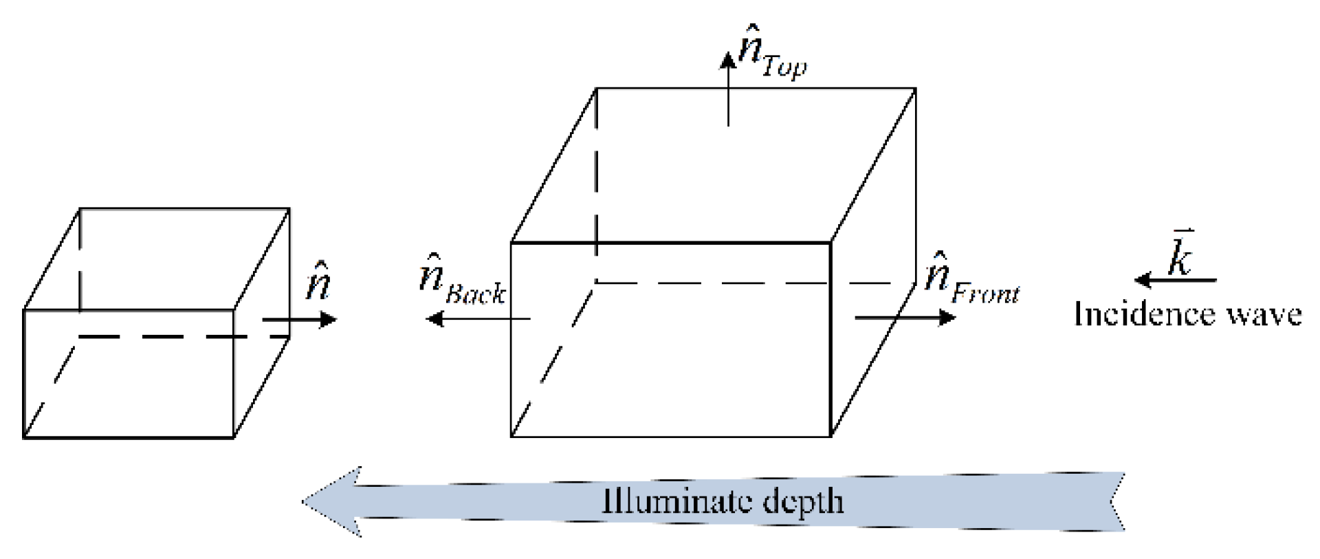
- Initially, eliminate the backward invisible faces based on the angle between the outward normal of the target surface element and the direction of the incident wave. As illustrated in Figure 3, if the dot product of the incident wave direction and the outward normal of a particular model surface element is greater than 0, then that surface element is considered a backward invisible face. For simple targets, determining the illuminated and shadowed regions can be achieved solely through the backward face elimination method.
- Utilize an orthogonal projection to transform the three-dimensional geometric data of the model into two-dimensional data on the screen for display. Implementing the hardware depth testing mechanism, conduct depth buffer tests in graphics hardware to accurately determine the visibility of each pixel, ensuring an efficient occlusion process.
- Obtain the model-view matrix, projection matrix, and viewport matrix, and calculate the screen coordinates (x, y, z) of the surface element center. Here, x and y are the two-dimensional coordinates on the screen, and z is the depth value. Read the depth value of the corresponding pixel on the screen for the surface element center. If the z value is greater than the pixel's depth value, then the surface element is considered a hidden face.
Figure 4a shows the wireframe model of a certain fighter jet model before occlusion processing, while Figure 4b displays the wireframe model after occlusion. It is evident from the figures that the occlusion process effectively removes the obscured portions of the model, resulting in a well-defined occlusion effect.
4. Numerical Results and Discussion
The analysis of the scattering characteristics of dielectric-coated conducting targets is closely tied to the boundary conditions on the coated surface. IBC is commonly employed to solve boundary problems at the interface between conductive materials and coating materials. When the thickness of the coated dielectric layer is very thin, IBC can be used to simplify the calculations. The expression for the calculation of the surface impedance Z for the external electric and magnetic fields on the outer surface of the thin-layer coated dielectric is given by
In the equation, Z0 represents the wave impedance in free space, k0 is the propagation constant in free space, d is the thickness of the coated dielectric, and ε and μ are the permittivity and permeability of the coated dielectric layer, respectively.
This section will present three verification examples with increasing levels of complexity, aiming to demonstrate the superiority of the proposed hybrid method in terms of accuracy and efficiency compared to the Method of Moments – Finite Element Method (MoM-FEM) in FEKO. The chip set used for the computational platform is an Intel Core i7 – 12700 with a clock speed of 2.10 GHz, and the total memory is 64 GB.
4.1. Square Plate
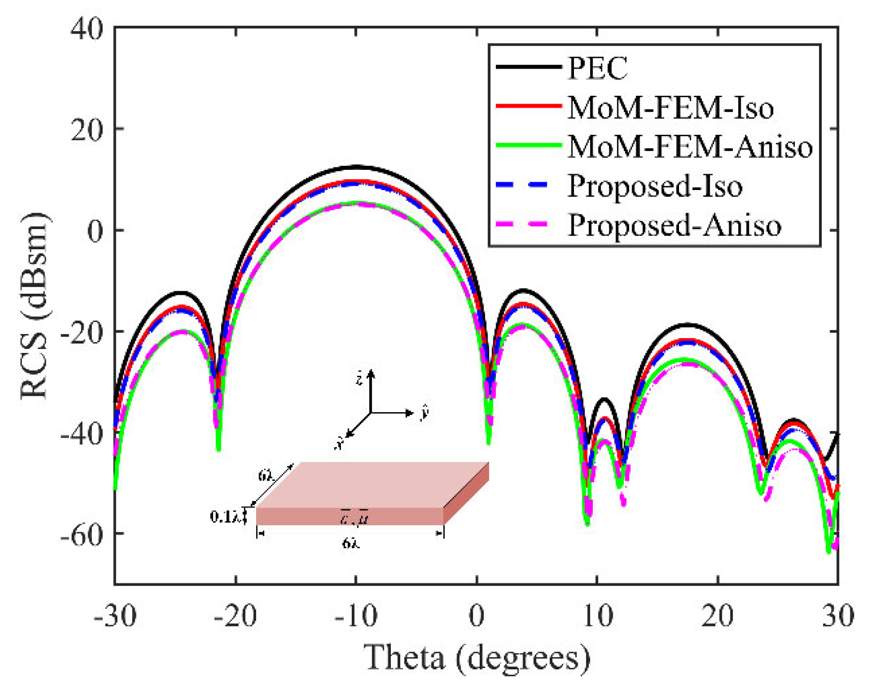
Figure 5 presents the Bistatic RCS simulation results on the surface of a square plate for two scenarios: one with isotropic dielectric coating and the other with anisotropic dielectric coating. The relative permittivity of the isotropic dielectric is ε = 15 – 15 j, and for the anisotropic dielectric, εuu = 5 – 7 j and εvv = 3 – 9 j. The thickness of the coating is d = 0.1 λ in both cases. The incident angle is θi = 10°, φi = 30°, and the observation angles are θs = –30° to 30°, φs = 30°. The incident wave frequency is 1 GHz with VV polarization. In the figure, "Iso" indicates the case with isotropic dielectric coating, and "Aniso" indicates the case with anisotropic dielectric coating.
For the isotropic dielectric coating case, the root mean square error (RMSE) between the results of the proposed method and the numerical method is 0.82 dB. In the case of anisotropic coating, the RMSE result is 1.57 dB, which is less than 3 dB. The comparative results demonstrate that the proposed hybrid algorithm results are in good agreement with the full-wave numerical solution, providing strong evidence for the applicability of the proposed method to open structures like square plates.
Figure 5.
The Bistatic RCS of square plate with isotropic and anisotropic dielectric coatings resulted in RMSE of 0.82 dB and 1.57 dB, respectively.
Figure 5.
The Bistatic RCS of square plate with isotropic and anisotropic dielectric coatings resulted in RMSE of 0.82 dB and 1.57 dB, respectively.
4.2. Aircraft Target
The geometric of an aircraft is depicted in Figure 6, where the red region represents the PO area, and the blue region represents the MoM area. The simulation results for the Bistatic RCS with isotropic dielectric coating on the surface are illustrated in Figure 7. The incident angles are θi = 10° and φi = 30°, while the scattering angles are θs = –90° - 270°, and φs = 30°. The incident wave frequency is 600 MHz with VV polarization. The relative permittivity of the isotropic dielectric is ε = 15 – 15 j, and the coating thickness is d = 0.1 λ.
In the figure, the green curve represents the simulation results obtained using the Ray-Launching Geometrical Optics (RL-GO) high-frequency solver in the FEKO software. Within the angular range of -45°, 43°, and 260°, the green curve exhibits noticeable errors. The RMSE between the RL-GO algorithm simulation results and the numerical solution is 3.91 dB, while the proposed method shows an RMSE of 1.56 dB compared to the numerical solution. Consequently, it can be concluded that current mainstream high-frequency solvers, on the one hand, cannot achieve RCS simulation for targets with anisotropic coating, and on the other hand, for RCS calculation of targets with isotropic coating, although they have lower memory requirements and computation time, their accuracy is lower than hybrid algorithms or numerical methods. The algorithm proposed in this paper is not only applicable to isotropic coating scenarios but also, through the application of IBC, provides EM characteristic data for targets with anisotropic coating. The computational efficiency is significantly superior to numerical simulation methods.
4.3. Complex Satellite Target
Figure 8 presents the simulated bistatic RCS results of a satellite target coated with anisotropic dielectric material, compared with the full-wave numerical solution. The top-left corner illustrates the coating effect on the satellite target's surface. The incident angle is θi = 120°, φi = 30°, and the scattering angles are θs = 0° – 360°, φs = 30°. The incident wave frequency is 800MHz, and the target's electrical size is 10 λ. The relative permittivity of the anisotropic material is εuu = 2 – 5 j and εvv = 3 – 7 j, with a coating thickness of d = 0.03 λ. Table 1 provides the required memory size and CPU computation time for the simulation process using the proposed method and MoM-FEM numerical method.
The hybrid method proposed in this paper demonstrates excellent agreement with full-wave numerical solutions for EM scattering from complex targets covered with anisotropic coatings over a wide angular range. The RMSE between the two is 2.64 dB, which is less than 3 dB, validating the high-precision characteristics of the proposed method. The resource comparison presented in Table 1 further highlights the efficiency advantages of the hybrid algorithm proposed in this paper. In conclusion, the use of the method presented in this paper enables accurate and rapid estimation of the RCS for complex coated targets.
5. Conclusions
This paper proposes an IBC-MoM-PO hybrid algorithm suitable for the EM scattering problems of complex targets covered with anisotropic coatings. The algorithm accelerates the PO visibility determination process using graphics hardware acceleration techniques. Based on IBC and the equivalent principle, the EM scattering problem of a thin-layer dielectric-coated conductive target is equivalently transformed into a radiation problem of equivalent EM currents on impedance surfaces. This enables high-precision and rapid estimation of EM scattering from material-coated targets. Numerical results validate the accuracy and effectiveness of the proposed method.
Future research efforts will focus on increasing the affordable electrical size of the targets, improving algorithm computational efficiency, and reducing memory requirements. Subsequent considerations include integrating the proposed method with popular fast algorithms such as fast multipole methods or multilevel UV methods [15], aiming for enhanced applicability to engineering problems.
Funding
This research received no external funding.
Conflicts of Interest
The authors declare no conflict of interest.
References
- Guo, S.J.; Wu, Y.M.; Wang, C.M.; et al. Analysis of the Electrically Large Target in Isotropic Medium by the Physical Optics Method with Adaptive Mesh Technique. IEEE Trans. Antennas Propag. 2023, 71, 6027–6036. [Google Scholar] [CrossRef]
- Yang, Z.; Yuan, X.W.; Huang, X.W.; et al. Resistive sheet boundary condition-based nonconformal domain decomposition FE-BI-MLFMA for electromagnetic scattering from inhomogeneous objects with honeycomb structures. IEEE Trans. Antennas Propag. 2022, 70, 9483–9496. [Google Scholar] [CrossRef]
- Mao, Y.; Zhan, Q.; Wang, D.; et al. Modeling Thin 3-D Material Surfaces Using a Spectral-Element Spectral-Integral Method With the Surface Current Boundary Condition. IEEE Trans. Antennas Propag. 2021, 70, 2375–2380. [Google Scholar] [CrossRef]
- Rao, Z.; Zhu, G.; He, S.; et al. Simulation and Analysis of Electromagnetic Scattering from Anisotropic Plasma-Coated Electrically Large and Complex Targets. Remote Sens. 2022, 14, 764. [Google Scholar] [CrossRef]
- Huang, X.W.; Yang, M.L.; Sheng, X.Q. A simplified discontinuous Galerkin self-dual integral equation formulation for electromagnetic scattering from extremely large IBC objects. IEEE Trans. Antennas Propag. 2021, 70, 3575–3586. [Google Scholar] [CrossRef]
- Gao, H.W.; Yang, M.L.; Sheng, X.Q. A new SDIE based on CFIE for electromagnetic scattering from IBC objects. IEEE Trans. Antennas Propag. 2019, 68, 388–399. [Google Scholar] [CrossRef]
- Huang, X.W.; Sheng, X.Q. A discontinuous Galerkin self-dual integral equation method for scattering from IBC objects. IEEE Trans. Antennas Propag. 2019, 67, 4708–4717. [Google Scholar] [CrossRef]
- Guo, L.; Li, M.; Xu, S.; et al. Modeling of Multiscale Wave Interactions Based on an Iterative Scheme of MoM-PO-EPA Algorithm. Electronics 2022, 11, 990. [Google Scholar] [CrossRef]
- Xue, Z.Y.; Wu, Y.M.; Jin, Y.Q. An Efficient iterative MoM-PO Hybrid Method for Calculating Scattered Fields of the Multiscale and Multiphysics Scatterers. In IEEE MTT-S International Conference on Numerical Electromagnetic and Multiphysics Modeling and Optimization (NEMO); IEEE: Piscataway, NJ, USA, 2020; pp. 1–3. [Google Scholar]
- Deng, J.Y.; Guo, L.X. An efficient octree-based Mom-PO method for analysis of antennas on large platform. IEEE Antennas Wirel. Propag. Lett. 2015, 14, 819–822. [Google Scholar] [CrossRef]
- Xiao, L.; Wang, X.H.; Wang, B.Z.; et al. An efficient hybrid method of iterative MoM-PO and equivalent dipole-moment for scattering from electrically large objects. IEEE Antennas Wirel. Propag. Lett. 2017, 16, 1723–1726. [Google Scholar] [CrossRef]
- Yu, D.F.; He, S.Y.; Chen, X.; et al. Simulation of electromagnetic scattering for 3-D impedance surface using MoM-PO method. IEEE Trans. Antennas Propag. 2012, 60, 3988–3991. [Google Scholar] [CrossRef]
- Zhou, H.; Wang, X.H.; Xiao, L.; et al. Efficient EDM-PO Method for the Scattering From Electrically Large Objects With the High-Order Impedance Boundary Condition. IEEE Trans. Antennas Propag. 2022, 70, 8242–8249. [Google Scholar] [CrossRef]
- Rao, S.; Wilton, D.; Glisson, A. Electromagnetic scattering by surfaces of arbitrary shape. IEEE Trans. Antennas Propag. 1982, 30, 409–418. [Google Scholar] [CrossRef]
- He, W.J.; Yang, Z.; Huang, X.W.; et al. High-Performance Evaluation of the Interpolations and Anterpolations in the GPU-Accelerated Massively Parallel MLFMA. IEEE Trans. Antennas Propag. 2023, 71, 6231–6236. [Google Scholar] [CrossRef]
Figure 1.
Schematic of target impedance surface.
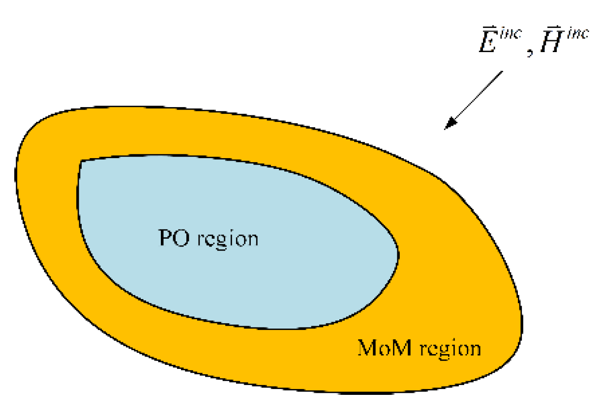
Figure 2.
Schematic of local coordinate system and anisotropic optical axis.
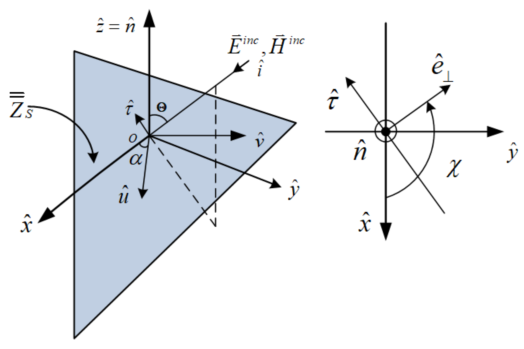
Figure 4.
Comparison of wireframe model for a complex aircraft target before and after occlusion
Figure 6.
Geometric of aircraft.
Figure 7.
The bistatic RCS of the aircraft under isotropic coating conditions has a RMSE of 3.91 dB for the RL-GO algorithm compared to the numerical solution, while the proposed method exhibits an RMSE of 1.56 dB compared to the numerical solution.
Figure 7.
The bistatic RCS of the aircraft under isotropic coating conditions has a RMSE of 3.91 dB for the RL-GO algorithm compared to the numerical solution, while the proposed method exhibits an RMSE of 1.56 dB compared to the numerical solution.
Figure 8.
The bistatic RCS of the satellite model coated with anisotropic dielectric material exhibits a RMSE of 2.64 dB.
Figure 8.
The bistatic RCS of the satellite model coated with anisotropic dielectric material exhibits a RMSE of 2.64 dB.

Table 1.
Comparison of CPU Computation Time and Memory Requirements for the Misty Satellite.
| Method | Unknown | Memory | Cal. Time (h) | |
|---|---|---|---|---|
| MoM | PO | |||
| MoM-FEM | 224403 | / | 9.8 | 11.8 |
| IBC-MoM-PO | 21891 | 202512 | 7.2 | 3.0 |
Disclaimer/Publisher’s Note: The statements, opinions and data contained in all publications are solely those of the individual author(s) and contributor(s) and not of MDPI and/or the editor(s). MDPI and/or the editor(s) disclaim responsibility for any injury to people or property resulting from any ideas, methods, instructions or products referred to in the content. |
© 2023 by the authors. Licensee MDPI, Basel, Switzerland. This article is an open access article distributed under the terms and conditions of the Creative Commons Attribution (CC BY) license (http://creativecommons.org/licenses/by/4.0/).
Copyright: This open access article is published under a Creative Commons CC BY 4.0 license, which permit the free download, distribution, and reuse, provided that the author and preprint are cited in any reuse.


