1. Introduction
Visual augmentation and telepresence are two concepts that aid in enhancing how we experience our environment. By understanding the mathematics that bring these ideas to life we can then apply them in a host of fields and tasks, using them to find solutions to the constraints of specific environments. Visual augmentation is the process of using computer generated perceptual information to enhance actual objects that reside in a physical plane [
1]. Telepresence highlights the human-machine partnership. It is the process where the sensory motor faculties of a human being are transferred to a machine. It also provides the illusion of being at multiple places at once, when the human and machine are placed in different environments [
2].
In the field of medical surgery these concepts can be used to enhance operations. Visual augmentation can be used to provide additional information to what can be seen by the naked eye. Organs can be highlighted, moved around, operated on and be accompanied by annotated labels and instructions. The added benefit of all of this happening in real-time provides a sense of simulation and practice, therefore improving the medical practitioners ability to do complex tasks- due to a greater understanding of the environment.
The application of these concepts are multifaceted. Telepresence can be used in space or deep-sea travel and exploration allowing a human being to circumvent oxygen constraints by transferring their sensory motor faculties to a machine that can operate in those environments. Visual augmentation can be used in the world of sports training. It enhances practice sessions be replicating scenarios that only take place in a competitive match, therefore giving players experiences of varying situations in a controlled environment and thus improving their ability to play the game at the highest level. Telepresence can be used in the world of mining or for any task where human safety is a concern. These concepts can also be used for entertainment purposes, social interactions and in professional settings.
Recent studies in visual augmentation [
3,
4], focus on immersive and non-immersive AR. These studies [
5,
6] use fiducial marker libraries to produce augmentation. The work of Avola et al [
7] provides a non-immersive framework for augmentation using ArUco markers, which plants the seed for the potential of AR applications as well as highlighting gaps in this area of research.
Studies [
1] have used approaches that utilise fiducial markers for augmentation but have been restricted to non-immersive environments. Latest research [
3,
8] in this area is therefore geared towards filling this gap by extending its functionality to immersive environments using head mounted displays as seen in the work of Bambusek et al [
5].
The ability for frameworks to utilise immersive environments increases their application and ability to be utilised in real-world problems [
9]. However self-contained visual augmentation robot models, still remains a gap. Studies, [
10] on applying AR to collaborative robotic work spaces, focus on incorporating AR into the user interface (UI) whether it is a UI for robot kinesthetic training [
5], safety interaction between human and robots in a collaborative workbench [
11] or allowing end users to manage robotic workplaces [
6]. In these studies the functionality of AR is not incorporated into the robot framework but rather it is used by the end user to aid in their interaction with the environment that houses a robotic system. AR is not a functional component of these robots and therefore this gap needs to be addressed.
Telepresence robot research makes a distinction between its functionality and that of video conferencing tools [
12] and yet the application- in industry- of the later outweighs the former [
13,
14]. Possible reasons lie in the visual immersion of these robots. Studies [
15,
16] have analysed how the functionality of a telepresence robot shapes our views of its usefulness.
In recent research [
17,
18,
19] these robots’ usefulness were evaluated in scenarios where a user has challenges with mobility. These studies show that the visual functionality of telepresence robots do not offer any additional benefit than those offered by video conferencing tools, resulting in fewer applications of these robots and in even-fewer fields of industry. In order to justify their use instead of other visual tools, the level of immersion offered by telepresence robots needs to be improved through research so that this limitation can be solved.
By addressing these gaps, these robots have the ability to not only display a live feed but also augment it. The added functionality increases its usefulness and application, therefore the solution lies in the integration of telepresence and augmentation.
To address the gaps in research on self-contained visual augmentation robot models- with an immersive AR functional component in its design- and the ability for telepresence robots to provide a greater level of visual immersion than live video streaming, this paper contributes:
An innovative augmentation algorithm that uses homography, image overlay, regions of interest (ROI) and ArUco markers to make changes to a virtual environment and provide a greater level of immersion when coupled with a virtual reality(VR)-headset
An innovative facial detection and recognition training model based on a limited self-collected and self-labelled dataset
An innovative facial recognition and detection algorithm that works in conjunction with the augmentation algorithm so that processing takes place simultaneously in order to provide the robot with more functionality
A mathematical and embedded system approach of using PWM and duty cycle for telepresence with regards to robot mobility and the mapping between the robot-head and the VR-headset
Telepresence experiments based on the relationship between accelerometer angles, duty cycles and digital signals. With the results and analysis of these experiments being used for improving stabilisation of the VAR model’s mobility and servo-head mapping
Augmentation and virtual plane experiments to qualitatively analyse the VAR model’s visual augmentation
A novel fully designed and implemented VAR model
1 that consists of a self-contained visual augmentation robot that offers immersion, telepresence and AR-functionality. Included in the VAR model is the design and implementation of the VAR application (app) which adds a web server hosting component of the augmented environment in real-time as well as a server-client network connection for robot mobility control
2. Related Work
The design and research of VAR is innovative, resulting in limitations with regards to equivalent studies which encompass multiple aspects of the conceptual idea. However previous work with homography [
20], fiducial [
21] and ArUco [
22] markers and telepresence robots [
12,
19,
23] laid the foundation for this research.
The study done by Avola et al. [
7] provides a collaboration between fiducial markers and augmented reality [
24,
25]. Their research highlights the benefits of using ArUco markers compared to alternative fiducial markers. Their approach uses a non-immersive application whereas the study of VAR contributes an immersive application.
In relation to this paper’s work with homography the work of DeTone et al. [
26] was of interest. They question if homography estimation could be taught using machine learning techniques and answered this question by presenting two Convolutional Neural Networks (CNNs). Their experiments focus on the homography error estimation of their pipelines, therefore the design of their pipelines consist of a 4-point homography parameterisation resulting in the use of a normalised direct linear transform. Their focus differs to this paper which requires an approach relying on ROI [
27], image overlay [
28], homography using source and destination points of a frame, masked matrices [
29] and warping [
30].
From a robotics standpoint, the telepresence robot is closely related to VAR. In recent years studies on the virtual telepresence robot in various forms have emerged [
31,
32,
33,
34,
35,
36,
37]. These studies range from observing how telepresence robots can be controlled in a simulated environment [
12] to the application of these systems in the healthcare field [
32] and as defence [
33] and survielance [
36] systems. The robotic motion and the VR aspects of these designs were of particular interest and share similarities. Differences lie in the networking capabilities, visual display, the level of immersion and the motion and visual control of the robot.
3. Method and Design
VAR is the integration of two unique states of reality, therefore it consists of two design aspects that were combined. With regards to hardware the Raspberry Pi [
38] and Pi Camera are the fundamental components and its software was implemented by designing and writing a single application that has C++ and python aspects.
Other studies of telepresence made use of multiple existing applications to perform networking tasks, robot control and mapping techniques. This resulted in a less integrated experience as well as less control over the robot’s design. VAR however requires a system that integrates all software aspects which then communicates with the hardware. Therefore, the VAR app was designed and implemented to give users more control of the system.
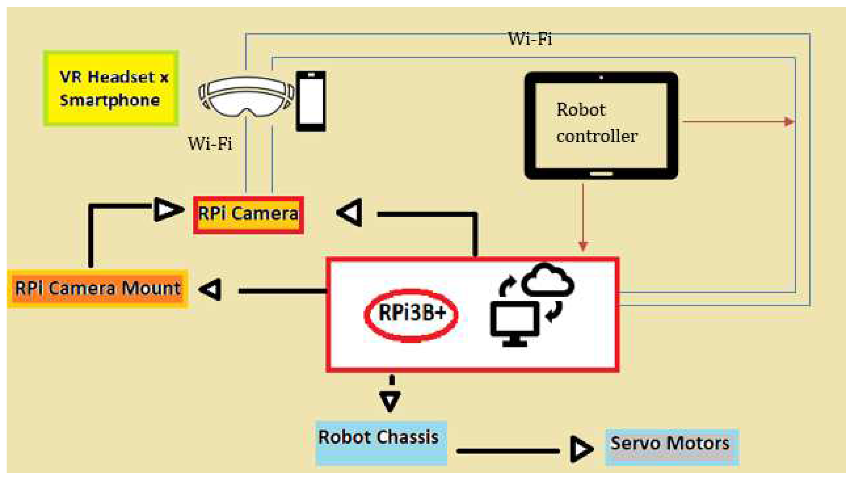
Figure 1.
Block diagram of the hardware components of VAR and an indication of how they interact with each other.
Figure 1.
Block diagram of the hardware components of VAR and an indication of how they interact with each other.
A WiFi module was preferred to a Bluetooth module (10 metres of connectivity) so as to provide a greater range of connectivity. Therefore transmission control protocol TCP [
39] was used to connect the VAR app to the actual robot and user datagram protocol UDP [
39] was used to map the accelerometer readings of the VR-smartphone headset to the RPi-Camera mount system.
3.1. Telepresence
The aim of this design was to give the illusion that a user can be at two places at a time. Using remote video conferencing tools provides this to an extent, but is limited by its lack of interactivity in both planes. To combat this, the design incorporates robot-human mapping and robot mobility.
3.1.1. Robot-Human Mapping
To produce the effect of the movement of the robot head, two servo motors were used for horizontal and vertical orientation. These servo motors were connected to a mounting structure that holds the Pi-Camera. The mounting system was then connected to the RPi3B+’s GPIO pins.
The robot’s head movements were a translation of the human’s head movements. A VR-smartphone headset was used not only to enhance the virtual experience, but to record changes in the human’s head movements. The raw accelerometer readings of the smartphone were converted into cartesian coordinates, which VAR used for horizontal and vertical head movements.
The raw accelerometer readings were parsed in three dimensions using UDP. These readings were the acceleration in the x-plane, y-plane and z-plane. These readings were used to calculate accelerometer angles in the x and y plane by applying 90°interval rotations to the original rotation angle of the servo motors. Therefore producing horizontal and vertical accelerometer angles:
The duty cycles for vertical and horizontal servo motion were set by the combination of the frequency of the PWM and the accelerometer angles. The stabilisation of these cycles then produced VR-headset to robot head mapping.
3.1.2. Robot Mobility
Interactivity in both locations, required movement in both locations. VAR had two wheels with each of them being controlled by its own motor. Each motor was connected to the RPi3B+ through the Pi’s GPIO pins. The pins were set as digital outputs and by setting them as a combination of HIGHs (1)s and LOWs (0)s the robot moved forward, backward, left and right.
Movement of the robot was only half of its interactivity. In order for VAR to be interactive in both locations, the user needed to be able to provide inputs that control how the robot behaved. The VAR app was designed to behave as a server-client network- where data was sent to and from the physical robot, the VR-smartphone headset and the VAR app. The connection was established using TCP/IP. A unique network address was established by using a static IP address and the mathematical AND operator in conjunction with a subnet mask- that was associated with the IP address class.
3.2. Virtual Plane
The foundation of this design was computer vision. The virtual plane was created by taking the robot’s vision and displaying it in such a way that a human had the ability to, not only visualise it but also modify it. This was designed in two parts. Firstly capturing live video streaming and secondly transmitting the live video.
The Raspberry Pi Camera (B) OV5647-Adjustable-Focus was used. It had a 5-megapixel sensor and a resolution of 1080p (19020x1080). OpenCV and matrices were used to capture the video frames and by continuously looping through the array of frames, live streaming was produced.
To transmit the live streaming from the robot to the user, the server-client network application (VAR app) was expanded. This relied on the use of socket and web server programming and OpenCV. The physical robot was established as the client and the VAR app as the server. The server was designed to listen to multiple requests, as different sections of VAR required connections to the same central network. A socket node that requested the sending of live video to the server was created.
The client was designed to read the array of frames from the raspberry pi camera and then request the sending of these frames to the server. The server was designed to listen for requests from multiple clients. It then accepted the frames sent by the virtual plane client and informed the client that the data had been received. Image processing was applied to the frames, and the result was live video streaming.
The image gradient vector was used for distinct pixels. It was used to indicate the gradient of pixels as a vector, compromising of the rate of colour change and the direction relative to the colour spectrum boundaries. The function worked by examining the four adjacent pixels to a selected pixel. Partial derivatives of adjacent pixels in the x-direction determined the colour difference to the left and right of the selected pixel. The same process was applied in the y-direction, where the partial derivatives determined the difference in the colour above and below the selected pixel.
Image processing through the use of the image gradient vector laid the foundation for object detection techniques to be applied for augmentation.
3.3. Augmentation
The modification of computer generated perceptual information provided another degree of interactivity. Interactivity in which the user was able to make changes to their environment. This design combined computer vision with machine learning and a registry of images, videos and markers. The techniques of homography and histogram of oriented gradients (HOG) were used in VAR’s augmentation process.
3.3.1. Homography in the form of ArUco Markers
The design was dependant on the homography matrix. It allowed for the transformation between two planes using planar homography.
The homography matrix had eight degrees of freedom and it was a 3x3 matrix. For this specific application, normalisation was applied across the Z-axis- with = 1.
Homography from camera displacement was used, in order to transition from the first to the second plane of view.
denotes the camera pose and
K denotes the intrinsic matrix.
was represented in a homogeneous form with the aim of transforming a point in the object frame into the camera frame.
r values indicate the distortion coefficients. R is the rotation matrix (orientation of camera) and t denotes the position of the camera.
indicates the pose of the first camera frame.
indicates the pose of the second camera frame.
Equation 7 was applied to the first camera frame to transform one of its points to the second camera frame.
To determine the homography from the camera displacement the distance (
d), between the camera frame and the plane along the normalised plane, was used in conjunction with the normal vector (
n).
denotes the homography matrix- transforming points from one camera frame to another.
denotes the rotation matrix- rotation between the two frames of the camera.
denotes the translation vector between the camera frames.
Finally the projection homography matrix (
G) was determined by using the intrinsic matrix (
K), the euclidean homography (
H) and the scale factor (
)
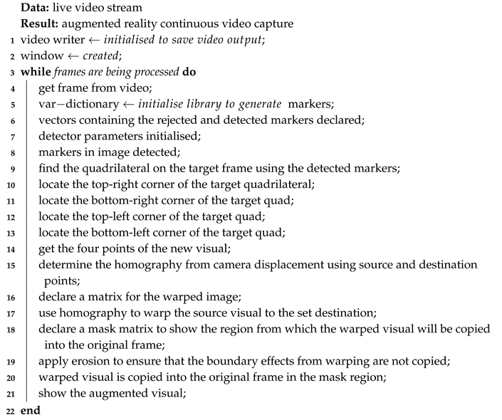
Algorithm 1 details the process used for augmentation using ArUco Markers.
|
Algorithm 1: Augmentation using Homography and ArUco Markers |
 |
3.3.2. Facial Recognition using a CNN
This technology used the detailing and distinct features of an individual face to record and analyse patterns. These patterns were then stored in a registry of faces. A CNN combined with the HOG method firstly enabled the detection of facial structures in images and videos. Secondly, it enabled recognition of these facial structures and finally it trained the system so the process could be repeated across a larger sample space.
The visual plane was already processed, thanks to Equation 3, with the gradient vector of every pixel calculated. The image displayed was then divided into 8x8 pixel cells, with 64 magnitudes separated from their respective directions. A 16x16 pixel block was placed across the image, thus producing four histograms of four cells in each block region. The cells in each block region were concatenated into a one-dimensional vector, compromising of 36 values. The block vector was normalized, so as to have a weight unit. The HOG vector was then the combination of all the block vectors.
The method used for block normalization is:
v denotes the normalised vector, which contains all the histograms in a block region.
e denotes a small constant with its actual value being negligible.
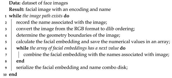
Algorithm 2 details the VAR CNN facial training process.
|
Algorithm 2: VAR CNN Facial Training |
 |
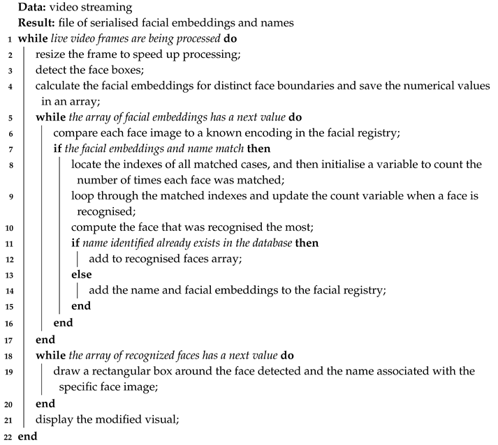
Algorithm 3 details the VAR facial recognition process.
|
Algorithm 3: VAR Facial Recognition |
 |
4. Empirical Evaluation
The functionality of the design was evaluated in three phases. Tests were performed to determine the success of the model’s telepresence, ability to generate a virtual plane and ability to augment a virtual plane.
4.1. Telepresence Experiment
The experiment was conducted by testing the raspberry pi camera and servo motor mapping, and testing the robot mobility in four directions. Servo motor mapping was tested for both vertical and horizontal motion. Using PWM the degree of movement was controlled. The experiment correlates duty cycles, orientation and accelerometer angles with the aim of inferring motion. The robot mobility aspect of the experiment compares the server input and the initialised and enabled GPIO pins to their corresponding digital outputs, in order to determine movement.
4.2. Augmentation and Virtual Plane Experiments
The generation of a web-server connection using an IP address and the creation of an application- that enables the loading of images and live video streaming- were evaluated.
The ArUco marker and CNN designs were tested. Facial recognition was evaluated by determining the accuracy of a face to the information displayed on the virtual plane once the face had been detected. Tests were also performed to evaluate the accuracy of the feature when different mediums were used to display a face, when lighting was altered and when hairstyles and accessories were changed.
The use of ArUco markers and homography was examined by the correlation between the source points, destination points, height, status, warped homography and mask region of the augmented visual. This was visualised by comparing images/videos of the original frame with images/videos of the masked warped visual, superimposed on the original frame-in the mask region.
5. Results and Discussion
5.1. Telepresence
Using equations
1 and
2, applying 90° interval movements and correlating the angular rotation of the servo, results in the values and relationships between the accelerometer angles, the duty cycles and the orientation of the servo-head mapping as seen in
Table 1. The average accelerometer angles and duty cycles in the x-y directions were used to establish the four directions of orientation.
The tests showed that duty cycles- relating to the horizontal motion- smaller than 6.9ms produced a left servo-head movement. This in term produced a vertical duty cycle of 4.2± 0.3 ms. Therefore for horizontal motion, the vertical duty cycle is dependent on the horizontal duty cycle and this relationship stabilises the head movement. The stabilisation of the servo-head movement is what reinforces telepresence. In the same way the results of the test showed that a horizontal duty cycle greater than 7.2ms translated to a right direction of orientation. Further analysis shows that for stabilisation a vertical duty cycle of 2.9± 0.1ms was produced as a result.
The servo-head mapping function representing telepresence is visualised in Figure 4. Tests were also conducted to determine vertical stabilisation.
Table 1 shows that the average vertical duty cycle for upward orientation is 2.4ms. Analysing this result revealed that a vertical duty cycle less than 5ms would produce the same upward orientation.
Similar to horizontal motion mapping, without stabilisation telepresence is not accurately represented. Tests showed that for upward orientation a horizontal duty cycle of 7.2±0.1ms was produced. Therefore the correlation between the vertical and horizontal duty cycles resulted in upward orientation stability. For downward orientation the average vertical duty cycle is 10.1ms.
Analysis showed that a vertical duty cycle greater than 5ms would produce a stabilising horizontal duty cycle of 7.1±0.1ms. Therefore stabilisation was achieved for four servo-head mapping orientations which establishes an accurate representation of telepresence.
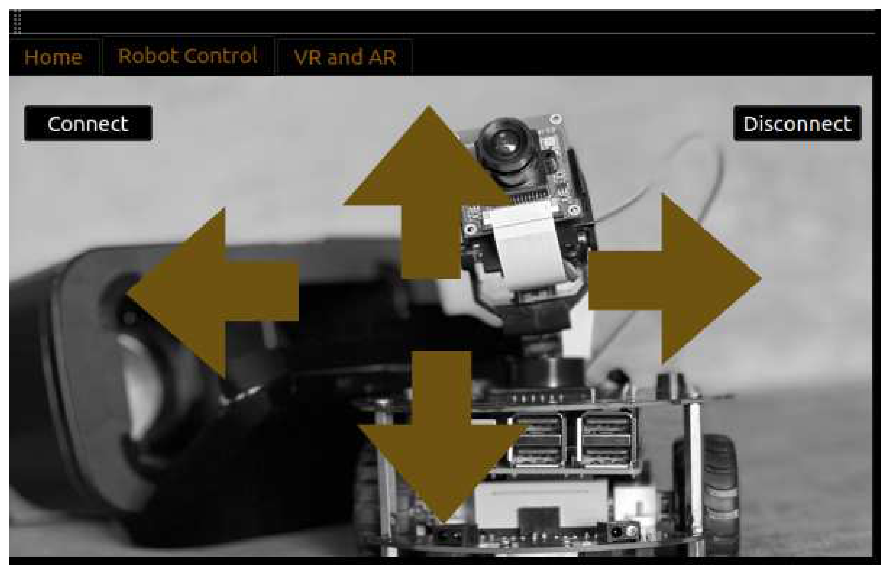
Figure 2 shows the graphical user interface of the VAR app. The app was built to serve as a server-client network to aid in robot mobility. Similar to the servo-head mapping function PWM and duty cycle were used to interpret wheel motion.
Figure 2.
Graphical user interface of the VAR app showing the robot control window. A server client network was created so that a button pressed on the app would result in the robot moving.
Figure 2.
Graphical user interface of the VAR app showing the robot control window. A server client network was created so that a button pressed on the app would result in the robot moving.
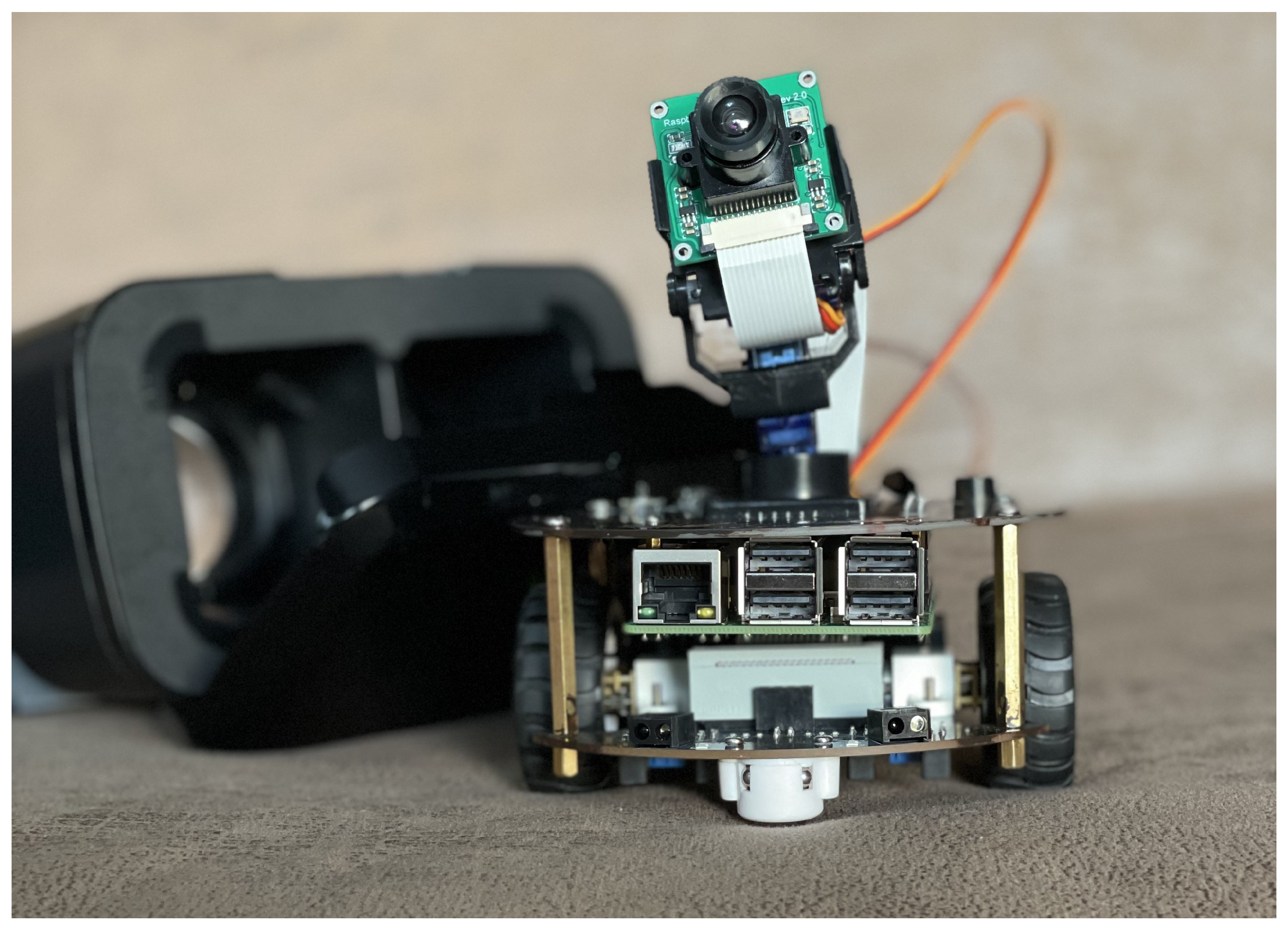
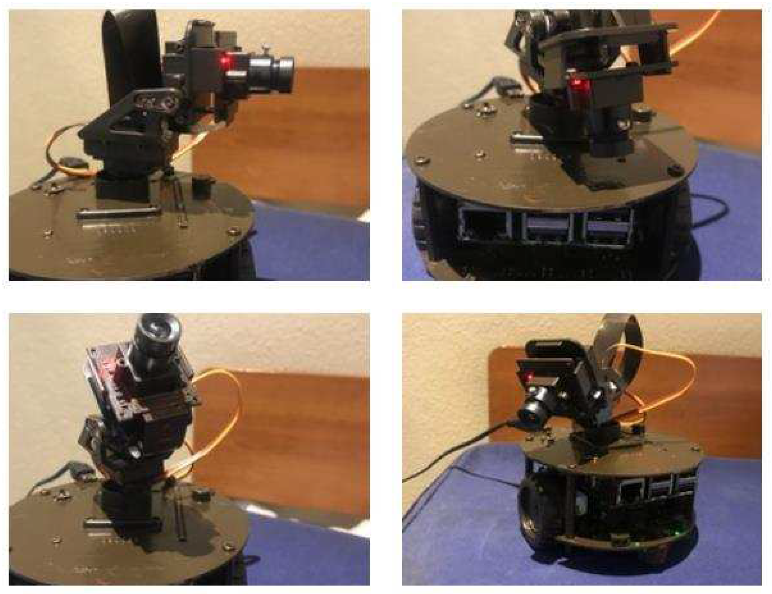
Figure 3.
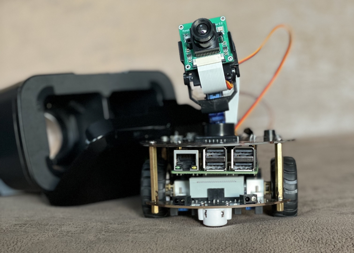
Physical implementation of the VAR model, consisting of an embedded designed robot and VR-smartphone-headset.
Figure 3.
Physical implementation of the VAR model, consisting of an embedded designed robot and VR-smartphone-headset.
Figure 4.
Servo-head mapping representation of telepresence. Four directions of orientation are mapped based on the accelerometer angles and duty cycles calculated from the VR-headset raw accelerometer data.
Figure 4.
Servo-head mapping representation of telepresence. Four directions of orientation are mapped based on the accelerometer angles and duty cycles calculated from the VR-headset raw accelerometer data.
VAR is an embedded system and therefore its design makes use of general purpose input/output (GPIO) pins for robot mobility. Tests were conducted to verify which GPIO pins and what signal levels would produce a specific motion.
Table 2 shows the relationship between the pin layout, signal level and robot motion. The tests showed that with regards to signal level, left and right motion were inverse of each other and forwards and backwards motion were also inverse of each other.
In
Table 2 the value 1 represents a digital HIGH signal and the value 0 represents a digital LOW signal. These digital signals act as an on and off switch for the motors attached to the wheels but it is the frequency of the PWM that dictates the signal output. Analysis of the signal levels shown in
Table 2 reveal that there is a frequency for each of the two motor wheels-
and
. Each motor wheel is designated two GPIO pins which are set to HIGH/LOW.
The
combination of column 1 and 2, row 2 and 4 of
Table 2 requires
ranging between
Hz represented by a backward traveling wave. The
combination of column 1 and 2, row 3 and 5 of
Table 2 requires
ranging between
Hz represented by a forward traveling wave. In the same way
ranges between
Hz for the
combination and between
Hz for the
combination.
It was necessary for robot mobility to be achieved as it highlights the distinction and advantages that telepresence has to video conferencing and other VR-tools.
5.2. Augmentation and Virtual Plane
A component of the VAR app (
Figure 2) was the creation of a virtual environment by means of an online web server for live video streaming. The augmentation algorithms could then be applied to the environment, resulting in the formation of the final VAR model. The model had to be trained based on a dataset of faces. The built encodings file from the training was then called whenever the facial recognition algorithm was applied.
The dataset contained 30 photos of a unique face, with images taken at different angles and with different facial expressions. All the images were captured by the same lens (5 megapixel camera) used for the live video streaming, therefore keeping the image quality constant. The images were also captured at the same time of day and with no accessories so as to establish a baseline when examining the accuracy of the trained model.
The model was trained on a 1.4GHz 64-bit quad-core processor with 30 photos being analysed and an encodings file being built in 135 seconds. Tests were conducted to determine the accuracy of the model with regards to detecting known faces in real-time when various accessories were worn.
Figure 5 shows that the model was knowledgeable enough to identify a face with accessories. This is of significance because it shows that the model was able to make accurate inference despite a limited dataset. However accurate inference could not be made using the same limited dataset, when examining facial recognition during the night with the only source of light being a 220-250 lumens lamp.
For improved accuracy the dataset will need to be extended to more than 30 photos, with images captured at different times of day under varying lighting conditions.
For augmentation using homography, tests showed that using multiple ArUco markers allowed for a larger region for visual overlay. Therefore, four ArUco markers were generated for use in the interactive environment. Tests were conducted to determine the detection of the markers, with larger sized markers being easier to detect at further distances.
A single large marker proved beneficial for detection but when four large markers were generated and placed in-frame the result was a distorted homography calculated from the source and destination points. This was because the displacement between source and destination points was too small, causing irregular shaped augmented visuals.
Therefore 200x200 pixel ArUco markers were generated, their orientations were configured based on each marker’s initial detection point. The markers were further resized using a scaling factor which was dependent on the various sizes selected for the live video streaming frame.
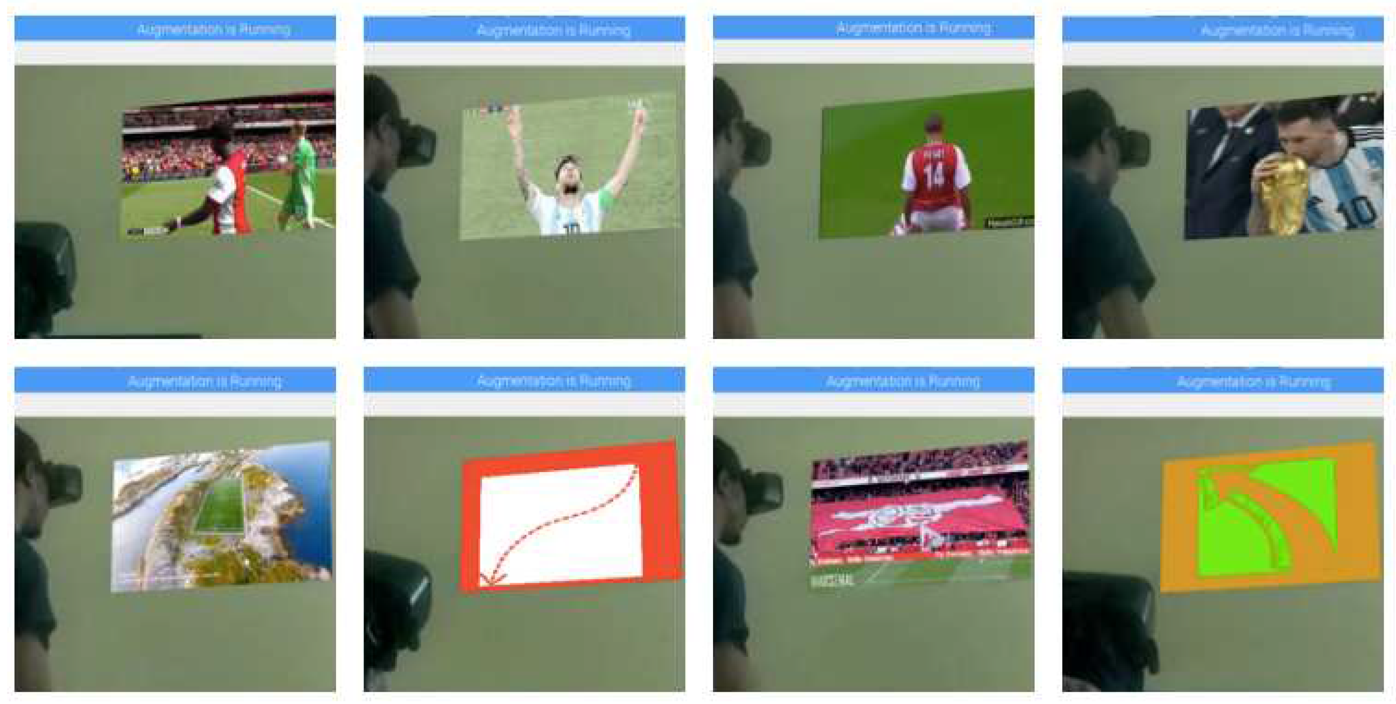
Figure 6 shows screenshots of the augmented virtual environment. Dynamic visuals were used for augmentation instead of still images so as to provide a sense of interactivity and immersion to the user.
6. Conclusions
This paper introduced the VAR model which addresses the problem of non-existing visual augmentation robots that have self-contained AR functionality. The model also provides an alternative solution to the limited visual experience offered by telepresence robots. VAR’s solution to this issue is to provide a greater level of immersion through the use of environment augmentation. The results of the experiments highlighted an innovative and successful approach of using the relationship between PWM, duty cycles, accelerometer angles and digital signals to stabilise robot motion and human robot motion mapping. The stabilisation of mapped movement can be shared with research in the field of bio-mechatronics.
The qualitative results of the augmentation-facial detection/recognition sub-model reveals the usefulness of this technology to provide an enhanced visual experience that cannot be replicated by the naked eye or video conferencing tools. This advanced level of visual immersion can be translated to multiple fields of industry. Also the analysis of the design of the VAR model shows how the sub-models and algorithms found in this paper help to bridge the gaps in telepresence robots and visual augmentation by integrating the two systems.
7. Future Work
The next stage of planned research in this area is to incorporate an intelligent agent- biometric of brain omnipotence (BOBO)- into the VAR model, using probabilistic machine learning. BOBO should provide autonomous motion to the model. It should improve processing performance of the augmentation-facial recognition sub-model. It should learn conditions for augmenting certain environments and improve the accuracy of mapping image overlay- found in its dataset- to these environments. BOBO should extend the telepresence component of VAR through the use of audio inputs.
Acknowledgments
Special thanks to Professor Adesola Illemobade for the refinement of the problem statement and scope of the research. Thanks to Dr and Mrs Gabriel and Gloria Francis, Seyi Olufolabi and Damilola Martins for the countless hours they spent discussing all aspects of the research.
References
- Arena, F.; Collotta, M.; Pau, G.; Termine, F. An Overview of Augmented Reality. Computers 2022, 11, 28. [Google Scholar] [CrossRef]
- Draper, J.V.; Kaber, D.B.; Usher, J.M. Telepresence. Human Factors: The Journal of the Human Factors and Ergonomics Society 1998, 40, 354–375. [Google Scholar] [CrossRef]
- Suzuki, R.; Karim, A.; Xia, T.; Hedayati, H.; Marquardt, N. Augmented Reality and Robotics: A Survey and Taxonomy for AR-Enhanced Human-Robot Interaction and Robotic Interfaces. In Proceedings of the 2022 CHI Conference on Human Factors in Computing Systems; CHI ’22; Association for Computing Machinery: New York, NY, USA, 2022. [Google Scholar] [CrossRef]
- Vaish, A.; Kalkati, I.M.; Rana, O. A REVIEW ON APPLICATIONS OF AUGMENTED REALITY PRESENT AND FUTURE. International Journal of Technical Research & Science 2020, Special, 69–74. [Google Scholar] [CrossRef]
- Bambusek, D.; Materna, Z.; Kapinus, M.; Beran, V.; Smrz, P. Combining Interactive Spatial Augmented Reality with Head-Mounted Display for End-User Collaborative Robot Programming. 2019 28th IEEE International Conference on Robot and Human Interactive Communication (RO-MAN) 2019, pp. 1–8.
- Kapinus, M.; Materna, Z.; Bambusek, D.; Beran, V.; Smrz, P. ARCOR2: Framework for Collaborative End-User Management of Industrial Robotic Workplaces using Augmented Reality. ArXiv 2023, abs/2306.08464. arXiv:abs/2306.08464.
- Avola, D.; Cinque, L.; Foresti, G.; Mercuri, C.; Pannone, D. A Practical Framework for the Development of Augmented Reality Applications by using ArUco Markers. Proceedings of the 5th International Conference on Pattern Recognition Applications and Methods ICPRAM, 2016, Vol. 1, pp. 645–654. doi:10.5220/0005755806450654. [CrossRef]
- Makhataeva, Z.; Varol, H.A. Augmented Reality for Robotics: A Review. Robotics 2020, 9. [Google Scholar] [CrossRef]
- Ryan, M.L. Immersion vs. Interactivity: Virtual Reality and Literary Theory. SubStance 1999, 28, 110–137. [Google Scholar] [CrossRef]
- Hietanen, A.; Pieters, R.; Lanz, M.; Latokartano, J.; Kämäräinen, J.K. AR-based interaction for human-robot collaborative manufacturing. Robotics and Computer-Integrated Manufacturing 2020, 63, 101891. [Google Scholar] [CrossRef]
- Tsamis, G.; Chantziaras, G.; Giakoumis, D.; Kostavelis, I.; Kargakos, A.; Tsakiris, A.; Tzovaras, D. Intuitive and Safe Interaction in Multi-User Human Robot Collaboration Environments through Augmented Reality Displays. 2021 30th IEEE International Conference on Robot & Human Interactive Communication (RO-MAN) 2021, pp. 520–526.
- Kalliokoski, J.; Sakcak, B.; Suomalainen, M.; Mimnaugh, K.J.; Chambers, A.P.; Ojala, T.; LaValle, S.M. HI-DWA: Human-Influenced Dynamic Window Approach for Shared Control of a Telepresence Robot. 2022 IEEE/RSJ International Conference on Intelligent Robots and Systems (IROS), 2022, pp. 7696–7703. [CrossRef]
- Papachristos, N.M.; Vrellis, I.; Mikropoulos, T. A Comparison between Oculus Rift and a Low-Cost Smartphone VR Headset: Immersive User Experience and Learning. 2017 IEEE 17th International Conference on Advanced Learning Technologies (ICALT) 2017, pp. 477–481.
- Flavián, C.; Ibáñez-Sánchez, S.; Orús, C. The impact of virtual, augmented and mixed reality technologies on the customer experience. Journal of Business Research 2019, 100, 547–560. [Google Scholar] [CrossRef]
- Lei, M.; Clemente, I.M.; Liu, H.; Bell, J. The Acceptance of Telepresence Robots in Higher Education. International Journal of Social Robotics 2022, 14, 1025–1042. [Google Scholar] [CrossRef]
- Schouten, A.P.; Portegies, T.C.; Withuis, I.; Willemsen, L.M.; Mazerant-Dubois, K. Robomorphism: Examining the effects of telepresence robots on between-student cooperation. Computers in Human Behavior 2022, 126, 106980. [Google Scholar] [CrossRef]
- Koceski, S.; Koceska, N. Evaluation of an Assistive Telepresence Robot for Elderly Healthcare. Journal of Medical Systems 2016, 40. [Google Scholar] [CrossRef]
- Cesta, A.; Cortellessa, G.; Orlandini, A.; Tiberio, L. Long-Term Evaluation of a Telepresence Robot for the Elderly: Methodology and Ecological Case Study. International Journal of Social Robotics 2016, 8, 421–441. [Google Scholar] [CrossRef]
- Zhang, G.; Hansen, J.P. Telepresence Robots for People with Special Needs: A Systematic Review. International Journal of Human–Computer Interaction 2022, 38, 1651–1667. [Google Scholar] [CrossRef]
- Malis, E.; Vargas, M. Deeper understanding of the homography decomposition for vision-based control. Technical Report RR-6303, INRIA, 2007.
- Fiala, M. Designing Highly Reliable Fiducial Markers. IEEE Transactions on Pattern Analysis and Machine Intelligence 2010, 32, 1317–1324. [Google Scholar] [CrossRef]
- Garrido-Jurado, S.; Muñoz-Salinas, R.; Madrid-Cuevas, F.; Marín-Jiménez, M. Automatic generation and detection of highly reliable fiducial markers under occlusion. Pattern Recognition 2014, 47, 2280–2292. [Google Scholar] [CrossRef]
- Bergamasco, M.; Herr, H. Human–Robot Augmentation. In Springer Handbook of Robotics; Siciliano, B., Khatib, O., Eds.; Springer International Publishing: Cham, 2016; pp. 1875–1906. [Google Scholar] [CrossRef]
- Azuma, R.T. A Survey of Augmented Reality. Presence: Teleoperators and Virtual Environments 1997, 6, 355–385. [Google Scholar] [CrossRef]
- Silva, R.; Oliveira, J.; Giraldi, G. Introduction to augmented reality. National Laboratory for Scientific Computation 2003. [Google Scholar]
- DeTone, D.; Malisiewicz, T.; Rabinovich, A. Deep image homography estimation. arXiv 2016, arXiv:1606.03798 2016. [Google Scholar]
- Vu, K.; Hua, K.; Tavanapong, W. Image retrieval based on regions of interest. IEEE Transactions on Knowledge and Data Engineering 2003, 15, 1045–1049. [Google Scholar] [CrossRef]
- Uenohara, M.; Kanade, T. Vision-based object registration for real-time image overlay. Computers in Biology and Medicine 1995, 25, 249–260. [Google Scholar] [CrossRef]
- Liu, Y.; Li, Y. Design of masking matrix for QC-LDPC codes. 2013 IEEE Information Theory Workshop (ITW), 2013, pp. 1–5. [CrossRef]
- Glasbey, C.A.; Mardia, K.V. A review of image-warping methods. Journal of Applied Statistics 1998, 25, 155–171. [Google Scholar] [CrossRef]
- Harikrishnan, N.; Soni, S.A.; Alex, A.M.; Menon, V.; Nair, V.C. Virtual Interactive Reality Telepresence Robot. Proceedings of the International Conference on Systems, Energy & Environment (ICSEE), 2021.
- ElGibreen, H.; Al Ali, G.; AlMegren, R.; AlEid, R.; AlQahtani, S. Telepresence Robot System for People with Speech or Mobility Disabilities. Sensors 2022, 22. [Google Scholar] [CrossRef] [PubMed]
- M P, S.; Kamala, N. Virtual Telepresence and Gesture Controlled Robot. International Journal of Research in Advent Technology 2018, 6, 1960–1965. [Google Scholar]
- Wanjre, M.; Kadam, A.; Bankar, G. Virtual Telepresence Robot. International Journal of Emerging Technologies and Innovative Research 2021, 8, 596–600. [Google Scholar]
- Reshma; Shilpa; Shubhashree; Dhanraj, A.; Deeksha. Virtual Telepresence Robot Using Raspberry Pi. International Journal of Research in Engineering, Science and Management 2020, 3, 365–368. [Google Scholar]
- Bhavyalakshmi, R.; Harish, B. Surveillance Robot with Face Recognition using Raspberry Pi. International Journal of Engineering Research & Technology (IJERT) 2019, 8. [Google Scholar]
- Swasthik, M.; Pawan, C.T.; Shankar, H.; Harshitha, V.; Vinay, N.A. SPi-Bot : A Gesture Controlled Virtual Telepresence Robot. International Journal of Modern Agriculture 2021, 10, 3782–3792. [Google Scholar]
- Severance, C. Eben Upton: Raspberry Pi. Computer 2013, 46, 14–16. [Google Scholar] [CrossRef]
- Xylomenos, G.; Polyzos, G. TCP and UDP performance over a wireless LAN. IEEE INFOCOM ’99. Conference on Computer Communications. Proceedings. Eighteenth Annual Joint Conference of the IEEE Computer and Communications Societies. The Future is Now (Cat. No.99CH36320), 1999, Vol. 2, pp. 439–446 vol.2. [CrossRef]
| 1 |
Some demonstration and implementation of VAR can be found in this repository. If the repository is private at the time of access, feel free to send an email stating your purpose for desired access |
|
Disclaimer/Publisher’s Note: The statements, opinions and data contained in all publications are solely those of the individual author(s) and contributor(s) and not of MDPI and/or the editor(s). MDPI and/or the editor(s) disclaim responsibility for any injury to people or property resulting from any ideas, methods, instructions or products referred to in the content. |
© 2023 by the authors. Licensee MDPI, Basel, Switzerland. This article is an open access article distributed under the terms and conditions of the Creative Commons Attribution (CC BY) license (http://creativecommons.org/licenses/by/4.0/).
