Submitted:
12 December 2023
Posted:
14 December 2023
You are already at the latest version
Abstract
Keywords:
1. Introduction
- Energy issue: Energy is a limitation of the underwater sensor network, as batteries do not have solar energy to charge and are not easily replaced. Therefore, routing protocols should consider energy saving a critical element because the node is dead after the energy runs out and may cause the project to fail [6].
- Load Balancing: An optimal routing protocol uses network resources fairly and equitably. This approach can prevent the occurrence of bottlenecks or hotspots. Also, in case of such incidents, action should be taken to resolve the issue as soon as possible [7].
- Underwater Location: Underwater networks lack GPS location information, which is essential for reducing routing tables, locating neighbours, and preventing loops. The depth gauges on underwater nodes measure their depth based on the water level since GPS cannot be used in deep water. It is still a challenge to develop a routing protocol that uses only depth information and the neighbourhood list at the water level [8,9].
- Underwater sensor nodes are mobile and unstable due to environmental factors such as currents, collisions, and waves. Maintaining routing tables and paths makes it challenging, as the network topology constantly changes. Researchers are developing routing protocols that can adapt to node mobility and instability in the underwater environment [10].
- Lack of a fault detection system: If a failure or underwater network configuration problem occurs, it is not detected before retrieving and aggregating network data. This process may easily lead to the complete loss of the monitoring mission [11].
- Lack of real-time monitoring: Recorded data are unavailable at the base station until collection and processing. This process may occur several hours after each sampling [11].
2. Underwater Internet of Things architectures and challenges
- A.
- UIoT Architecture
- B.
- Routing in UIoT
- 1)
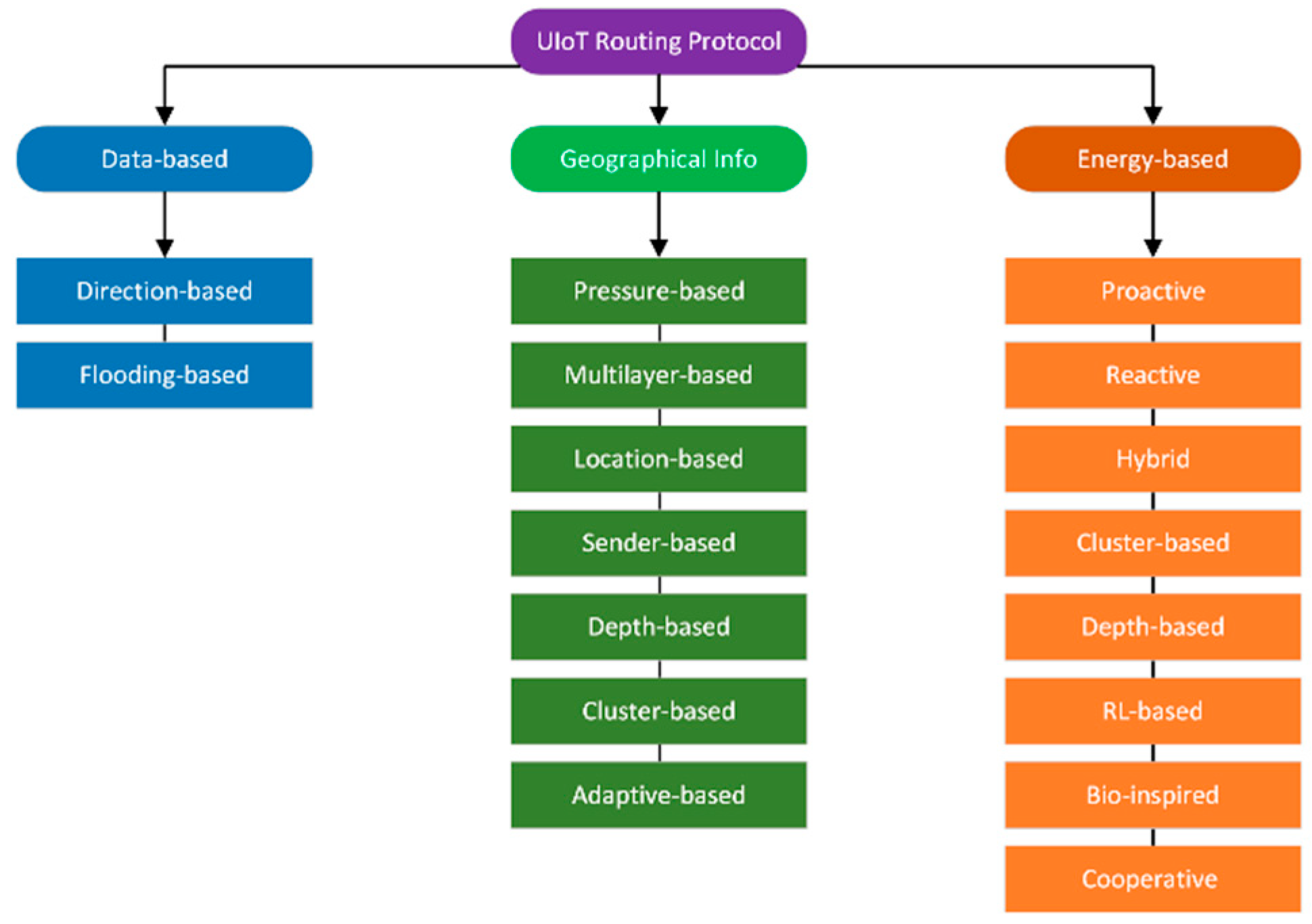
- Energy-based routing
- Active routing: Active routing protocols maintain routing tables that describe the overall network topology. This allows for faster packet delivery but requires more overhead to keep the tables.
- Hybrid routing: Hybrid routing protocols combine reactive and active routing to achieve the best of both worlds. They may use different routing mechanisms within and between regions of the network.
- Cluster-based routing: Cluster-based routing groups nodes into clusters and elects a cluster head for each cluster. Cluster heads collect data from member nodes and forward it to the sink node. This saves energy by reducing the number of nodes that transmit data directly to the sink node.
- Depth-based routing: Depth-based routing is a popular method for underwater IoT networks. It selects the next forwarding node based on its depth, prioritising nodes closer to the sink node. This reduces the number of hop packets that must traverse to reach the sink node.
- RL-based routing: Reinforcement learning (RL) is a machine learning technique that allows agents to learn how to behave in an environment by trial and error. RL-based routing protocols use RL to learn how to route packets in a way that maximises performance metrics such as throughput and packet delivery ratio.
- Bio-inspired routing: Bio-inspired routing protocols are heuristic algorithms inspired by natural processes. Some examples include ant colony optimisation (ACO), honeybee-inspired routing (HIBR), and frog-inspired routing (FIR) [16].
- RB routing: Reliability-based routing protocols are designed to improve the reliability of data transmission in underwater IoT networks. They typically work by selecting relay nodes that are less likely to experience errors. One common approach is cooperative-reliability routing, in which multiple relay nodes forward each packet. This can improve the packet delivery ratio and increase the end-to-end Delay and duplicate data transmission [16].
- 2)
- Routing based on geographic information
- Depth-based routing: only needs the depth of nodes to route packets, making it more straightforward and energy-efficient than methods that require complete location information.
- Location-based routing: it uses the geographic location of nodes to route packets, which can improve the efficiency and reliability of data transmission.
- Pressure-based routing: uses the water pressure at each node to determine its depth, making it a simple and effective way to route packets in underwater IoT networks.
- Sender-based routing: the sending node selects the next hop node based on its criteria and metrics, such as the remaining energy of the node or the distance to the destination.
- Cluster-based routing: groups nodes into clusters and elects a cluster head for each cluster. Cluster heads are responsible for routing packets between nodes in their cluster and between clusters. This method can improve the scalability and efficiency of routing in large networks.
- 3)
- Data-driven routing
- Direction-based routing: This method takes into account the direction of the packet movement in the path to improve data transmission efficiency.
- Flood routing: This is a simple and efficient routing method that does not require network topology or computational routing maintenance. It works by flooding the network with packets until they reach the destination node. This method is fault-tolerant but can also lead to resource wastage and internal message disclosure.
- C
- Recent QoS-based routing Protocol in UIoT
- [20] An underwater sensor network using AUVs was introduced to save energy and enhance data collection. They designed efficient algorithms for this purpose, but based on a greedy approach, their cluster head selection method can slow down the process, requiring additional computation.
- [21] Proposed a dataset using multiple AUVs in heterogeneous IoUT networks with optimisation (AoI). The proposed scheme uses a queuing model to enable information exchange between several AUVs and a low-complexity adaptive algorithm to control queue length and AUV energy constraints.
- [22] has devised an energy-efficient and low-latency data routing protocol for IoT networks. This protocol considers critical factors, including the energy levels of nodes, data transmission distance, data size, and available routing options. Considering these variables, the protocol ensures that data follows the most efficient path and avoids burdening nodes with limited energy.
- [23] has developed a new way to save energy in IoT networks by fixing network holes caused by long distances between nodes. The new algorithm uses a guard-based flooding scheme to fill the gaps, which is more efficient than other methods.
- [24] has proposed a new routing protocol for underwater sensor networks that is more energy-efficient than other protocols. The new protocol uses multi-hop communication and underwater relay nodes to transmit data, reducing the energy each node needs to consume. The new protocol has also been shown to provide the lowest total energy consumption compared to other well-known protocols.
- [25] has developed new routing protocols for underwater IoT devices that improve energy efficiency and QoS. These protocols use a clustering approach to group devices and opportunistic routing to transmit data between clusters. The new protocols have been shown to outperform current protocols in terms of both energy efficiency and QoS.
- The DSPR protocol is a new approach to underwater IoT networks that aims to improve energy efficiency and reliability. It does this by using directional routing and selective power control. However, more testing is needed to see how well it works in real-world environments [26].
- In [27] propose a new technique for localisation of underwater IoT devices that combines magnetic, optical, and audio communications. This technique is more accurate than previous techniques, but more research is needed to develop practical implementations.
- In [28], a new clustering protocol for underwater IoT networks that uses the k-means algorithm to select cluster heads is proposed. This protocol is simple and effective, but more research is needed to compare it to other clustering protocols specifically designed for underwater IoT networks.
3. The Proposed Method
- The sink node broadcasts the DIO packet to all nodes in the underwater network environment.
- Nodes within radio range of the well receive the DIO packet from the well and send the DAO packet to the well, which includes the well’s depth and the link ARSSI rate.
- The sink node sends DAO-Ack packets to the first-level nodes because it has unlimited one-hop children.
- In the DIO packet, the parent nodes update their hop values, depth, and ARSSI rate for the well.
- Upon receiving the DIO packet from the available parents, each network node compiles a list in its memory, and the list is updated in response to the values sent by the parents.
- In the case of a child node, the membership request packet is sent to selected parents (more than one parent, if possible). Additionally, the DAO packet contains information regarding the depth of the child node and the level of ARSSI received from the parent node.
- As soon as the parent nodes receive the DAO packet, they send the DAO-Ack packet to any child nodes whose quality level is greater than the threshold value.
- As in step 4, the child nodes will continue in the next step after receiving the DAO-Ack packet. As the network graph progresses, this process will continue.
- A.
- Routing in the proposed network
- B.
- Simulation results
- 1)
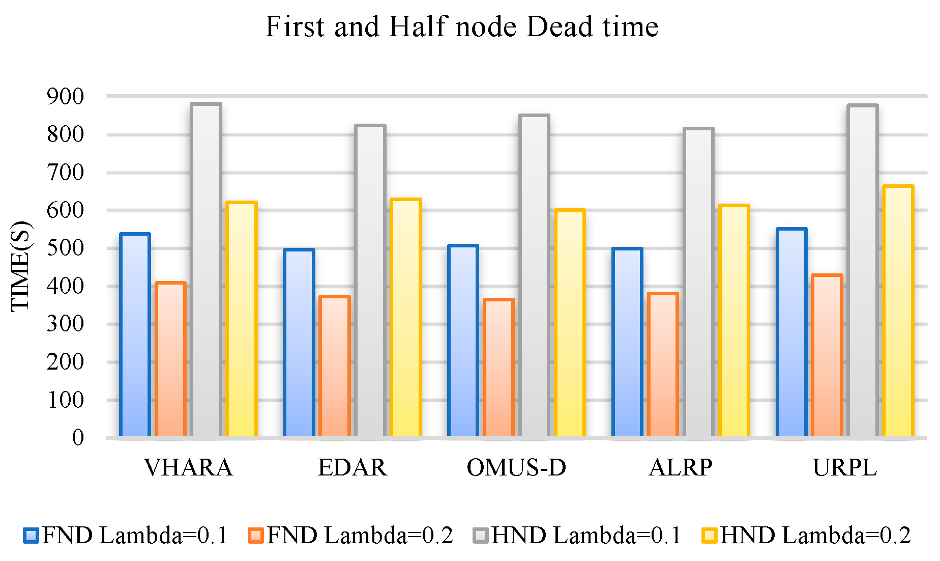
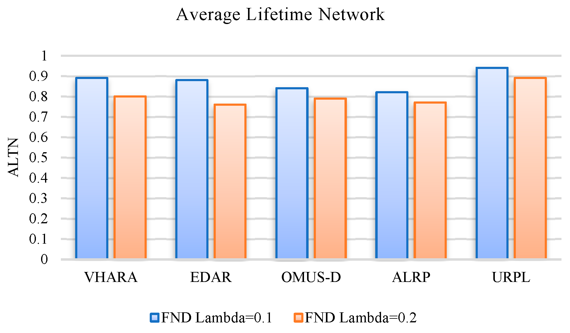
- Network Lifetime
- 2)
- Packet Delivery Ratio
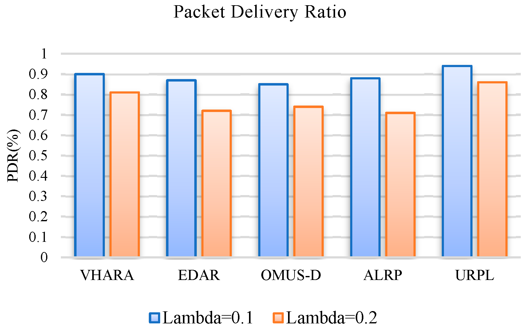
- 3)
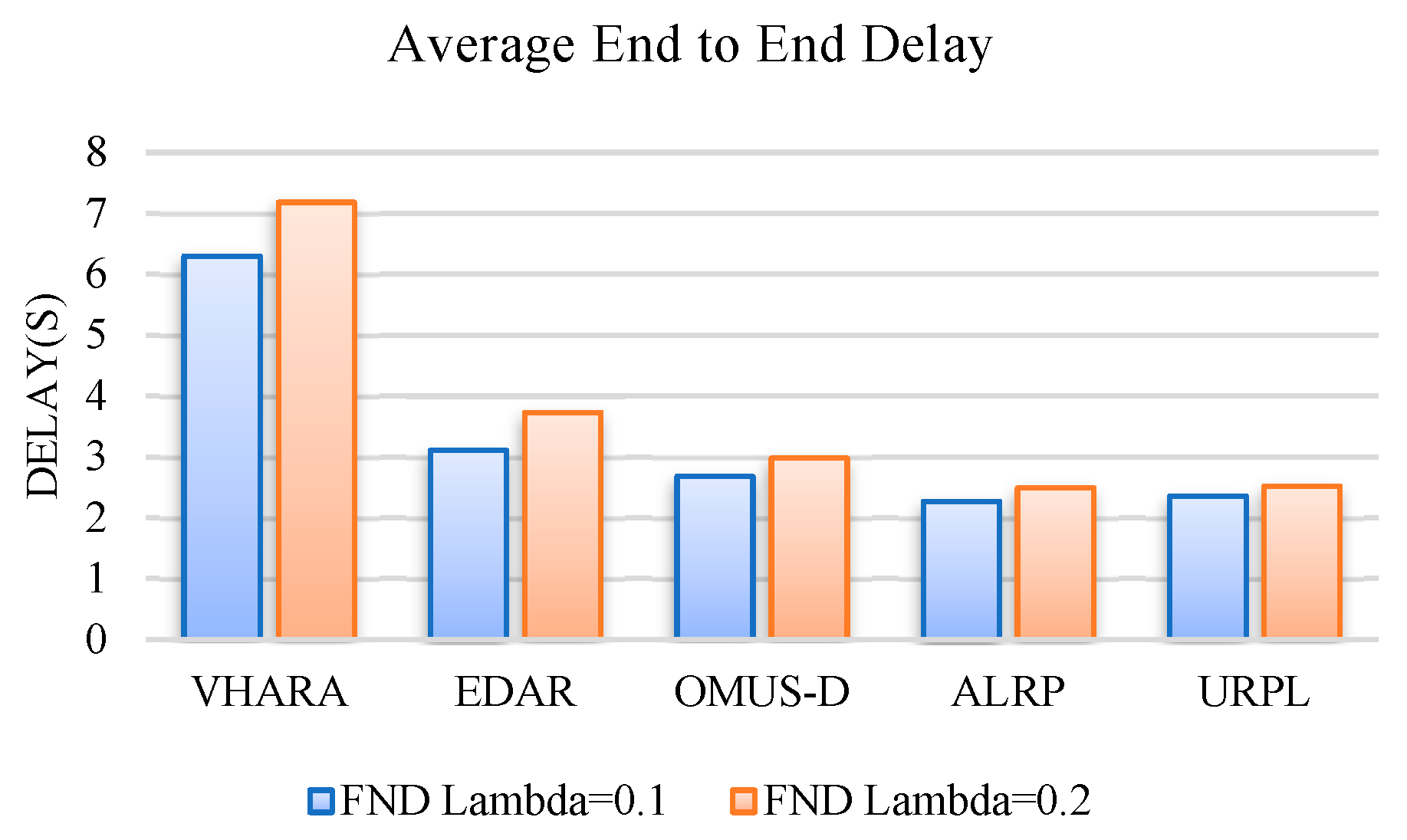
- End-to-End Delay
- 4)
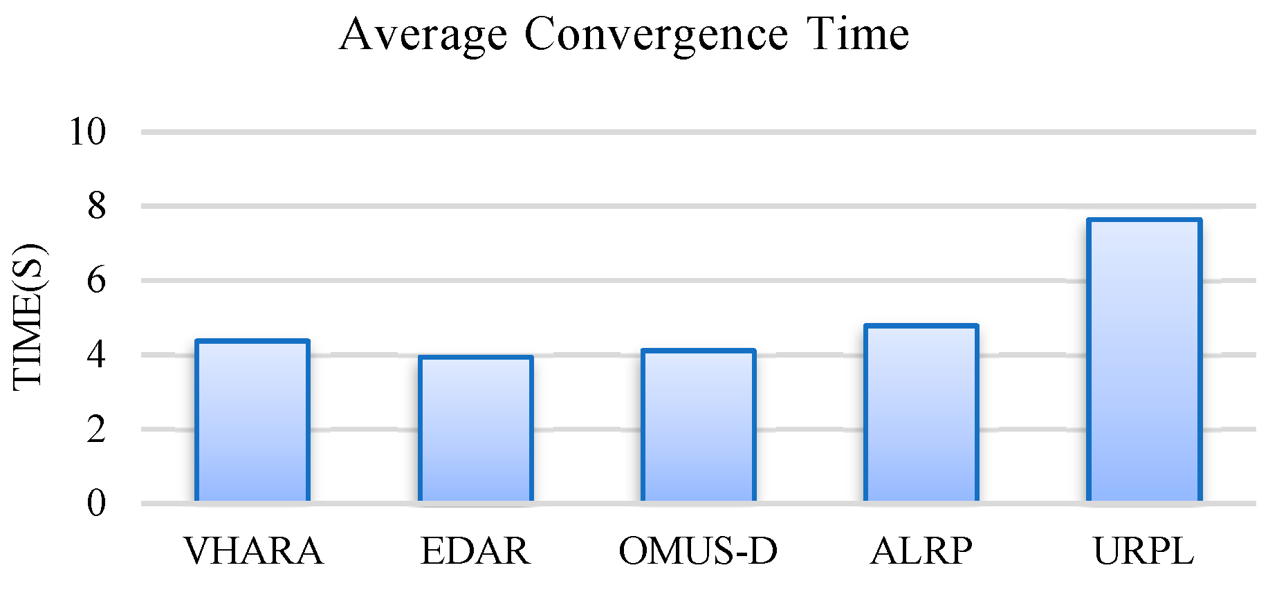
- Network Convergence Time
4. Conclusion
References
- Y. Alharbi and A. Ahmad, "Underwater Internet of Things to Analyse Oceanic Data," IETE J. Res., pp. 1–14, Feb. 2022. [CrossRef]
- D. R. K. Mary, E. Ko, S.-G. Kim, S.-H. Yum, S.-Y. Shin, and S.-H. Park, "A Systematic Review on Recent Trends, Challenges, Privacy and Security Issues of Underwater Internet of Things," Sensors, vol. 21, no. 24, p. 8262, Dec. 2021. [CrossRef]
- E. Ko, D. Raj, S.-Y. Shin, S.-G. Kim, and S.-H. Park, "International Standardization for Maritime, Underwater Internet of Things and Digital Twin Applications," in The 15th International Conference on Underwater Networks & Systems, New York, NY, USA: ACM, Nov. 2021, pp. 1–2. [CrossRef]
- H. Chen, Y. Zhu, W. Zhang, K. Wu, and F. Yuan, "Underwater Acoustic Micromodem for Underwater Internet of Things," Wirel. Commun. Mob. Comput., vol. 2022, pp. 1–20, Sep. 2022. [CrossRef]
- E. Ko, K. M. R. Delphin, S.-Y. Shin, H. Choe, and S.-H. Park, "Underwater Internet of Things: Standardization Strategy," in 2022 13th International Conference on Information and Communication Technology Convergence (ICTC), IEEE, Oct. 2022, pp. 1852–1854. [CrossRef]
- S. A. H. Mohsan, Y. Li, M. Sadiq, J. Liang, and M. A. Khan, "Recent advances, future trends, applications and challenges of internet of underwater things (iout): a comprehensive review," J. Mar. Sci. Eng., vol. 11, no. 1, p. 124, 2023.
- M. Ayaz, M. Ammad-Uddin, Z. Sharif, M. Hijji, and A. Mansour, "A hybrid data collection scheme to achieve load balancing for underwater sensor networks," J. King Saud Univ. Inf. Sci., vol. 35, no. 3, pp. 74–86, 2023.
- Pourkabirian, F. Kooshki, M. H. Anisi, and A. Jindal, "An accurate RSS/AoA-based localisation method for internet of underwater things," Ad Hoc Networks, vol. 145, p. 103177, 2023.
- Y. Wang, S. Song, X. Guo, J. Liu, Q. Ye, and J. Cui, "An Efficient Localisation Scheme With Velocity Prediction for Large-Scale Underwater Acoustic Sensor Networks," IEEE Internet Things J., 2023.
- S. A. H. Mohsan, A. Mazinani, N. Q. H. Othman, and H. Amjad, "Towards the internet of underwater things: a comprehensive survey," Earth Sci. Informatics, pp. 1–30, 2022.
- Sazzad, N. Nawer, M. Mahbub Rimi, K. Habibul Kabir, and K. Foysal Haque, "Designing of an Underwater-Internet of Things (U-IoT) for Marine Life Monitoring," in The Fourth Industrial Revolution and Beyond: Select Proceedings of IC4IR+, Springer, 2023, pp. 291–303.
- S. Sandhiyaa and C. Gomathy, "A Survey on underwater wireless sensor networks: challenges, requirements, and opportunities," in 2021 Fifth International Conference on I-SMAC (IoT in Social, Mobile, Analytics and Cloud)(I-SMAC), IEEE, 2021, pp. 1417–1427.
- R. Habibiyan and A. Ghorban Sabbagh, "Connectivity analysis of 2D underwater optical wireless sensor networks using a geometric approach," Ad Hoc Networks, vol. 134, p. 102910, Sep. 2022. [CrossRef]
- Bello and S. Zeadally, "Internet of underwater things communication: Architecture, technologies, research challenges and future opportunities," Ad Hoc Networks, vol. 135, p. 102933, 2022.
- Ragavi, V. Baranidharan, A. John Clement Sunder, L. Pavithra, and S. Gokulraju, "A Comprehensive Survey on Different Routing Protocols and Challenges in Underwater Acoustic Sensor Networks," Recent Adv. Metrol., pp. 309–320, 2023.
- I. Shovon and S. Shin, "Survey on Multi-Path Routing Protocols of Underwater Wireless Sensor Networks: Advancement and Applications," Electronics, vol. 11, no. 21, p. 3467, 2022.
- M. Nain and N. Goyal, "Localisation techniques in underwater wireless sensor network," in 2021 International Conference on Advance Computing and Innovative Technologies in Engineering (ICACITE), IEEE, 2021, pp. 747–751.
- J. Jiang, G. Han, and C. Lin, "A survey on opportunistic routing protocols in the Internet of Underwater Things," Comput. Networks, vol. 225, p. 109658, Apr. 2023. [CrossRef]
- E. S. Ali, R. A. Saeed, I. K. Eltahir, and O. O. Khalifa, "A systematic review on energy efficiency in the internet of underwater things (IoUT): Recent approaches and research gaps," J. Netw. Comput. Appl., vol. 213, p. 103594, Apr. 2023. [CrossRef]
- X. Zhuo, M. Liu, Y. Wei, G. Yu, F. Qu, and R. Sun, "AUV-Aided Energy-Efficient Data Collection in Underwater Acoustic Sensor Networks," IEEE Internet Things J., vol. 7, no. 10, pp. 10010–10022, Oct. 2020. [CrossRef]
- Z. Fang, J. Wang, C. Jiang, Q. Zhang, and Y. Ren, "AoI-Inspired Collaborative Information Collection for AUV-Assisted Internet of Underwater Things," IEEE Internet Things J., vol. 8, no. 19, pp. 14559–14571, Oct. 2021. [CrossRef]
- W. Xu, R. He, and C. Yu, "Energy Efficient Routing for Multi-modal Underwater Wireless Sensor Networks," in 2021 International Conference on Security, Pattern Analysis, and Cybernetics (SPAC), IEEE, Jun. 2021, pp. 516–520. [CrossRef]
- U. Draz et al., "Energy efficient watchman based flooding algorithm for IoT-enabled underwater wireless sensor and actor networks," ETRI J., vol. 43, no. 3, pp. 414–426, Jun. 2021. [CrossRef]
- K. Bhattacharjya, S. Alam, and D. De, "CUWSN: energy efficient routing protocol selection for cluster based underwater wireless sensor network," Microsyst. Technol., vol. 28, no. 2, pp. 543–559, Feb. 2022. [CrossRef]
- V. G. Menon, D. Midhunchakkaravarthy, A. Sujith, S. John, X. Li, and M. R. Khosravi, "Towards Energy-Efficient and Delay-Optimized Opportunistic Routing in Underwater Acoustic Sensor Networks for IoUT Platforms: An Overview and New Suggestions," Comput. Intell. Neurosci., vol. 2022, 2022.
- D. R. Kesari Mary, E. Ko, D. J. Yoon, S.-Y. Shin, and S.-H. Park, "Energy Optimisation Techniques in Underwater Internet of Things: Issues, State-of-the-Art, and Future Directions," Water, vol. 14, no. 20, p. 3240, Oct. 2022. [CrossRef]
- R. A. Khalil, N. Saeed, M. I. Babar, T. Jan, and S. Din, "Bayesian Multidimensional Scaling for Location Awareness in Hybrid-Internet of Underwater Things," IEEE/CAA J. Autom. Sin., vol. 9, no. 3, pp. 496–509, Mar. 2022. [CrossRef]
- L. Li, Y. Qiu, and J. Xu, "A K-Means Clustered Routing Algorithm with Location and Energy Awareness for Underwater Wireless Sensor Networks," Photonics, vol. 9, no. 5, p. 282, Apr. 2022. [CrossRef]
- M. H. Saleh, H. Takruri, and N. Linge, "Energy aware routing protocol for sparse underwater acoustic wireless sensor network," in 2022 13th International Symposium on Communication Systems, Networks and Digital Signal Processing (CSNDSP), IEEE, Jul. 2022, pp. 750–755. [CrossRef]
- J. M. Alostad, N. Alkateeb, E. Sultan, and H. K. Ebraheem, "IOUT Enabled Underwater WSN Using Dynamic Adaptive Routing Protocol with Improved Reliability," J. Commun., vol. 15, no. 8, pp. 607–612, 2020. [CrossRef]
- R. W. L. Coutinho and A. Boukerche, "OMUS: Efficient Opportunistic Routing in Multi-Modal Underwater Sensor Networks," IEEE Trans. Wirel. Commun., pp. 1–1, 2021. [CrossRef]
- Q. Wang, J. Li, Q. Qi, P. Zhou, and D. O. Wu, "An Adaptive-Location-Based Routing Protocol for 3-D Underwater Acoustic Sensor Networks," IEEE Internet Things J., vol. 8, no. 8, pp. 6853–6864, Apr. 2021. [CrossRef]
- M. H. Homaei, S. S. Band, A. Pescape, and A. Mosavi, "DDSLA-RPL: Dynamic Decision System Based on Learning Automata in the RPL Protocol for Achieving QoS," IEEE Access, vol. 9, pp. 63131–63148, 2021. [CrossRef]
- V. Moghiss, M. R. Meybodi, and M. Esnaashari, "An intelligent protocol to channel assignment in wireless sensor networks: Learning automata approach," in 2010 International Conference on Information, Networking and Automation (ICINA), IEEE, Oct. 2010, pp. V1-338-V1-343. [CrossRef]
- M. Al-Bzoor, A. Musa, K. Alzoubi, and T. Gharaibeh, "A Directional Selective Power Routing Protocol for the Internet of Underwater Things," Wirel. Commun. Mob. Comput., vol. 2022, pp. 1–13, Feb. 2022. [CrossRef]
| Type | Description |
|---|---|
| 1D-UIoT | Sensors receive, process, and send information to the base station. |
| 2D-UIoT | Underwater sensor nodes (clusters) with cluster heads (anchor nodes) relay information to surface floating nodes. |
| 3D-UIoT | Extension of 2D-UIoT architecture, with clusters at different ocean depths. Nodes communicate within clusters, and cluster heads communicate with each other and the communication layer. |
| 4D-UIoT | Includes underwater vehicles (ROVs) and clusters at different ocean depths. ROVs collect information from cluster heads and relay it to floating objects. |
| Protocol | Algorithm | Method | Performance indicators | |||
|---|---|---|---|---|---|---|
| Energy Efficiency | Lifetime | QoS | Efficiency | |||
| [20] 2020 |
AEEDCO and AEEDCO-A to improve energy consumption in AUV | Optimising the performance of AUVs to maximise energy efficiency. | ✓ | High | Low | Justly |
| [21] 2021 |
AoI Optimisation in Heterogeneous IoT Network | Improved queuing model to enable information exchange between multiple AUVs | ✓ | Low | Low | Justly |
| [22] 2021 |
Improved Energy Efficiency Routing Protocol | Balancing traffic load between nodes with higher residual energy | ✓ | Low | Low | Low |
| [23] 2021 |
Guard-based flood pattern | Reducing energy consumption by solving the problem of holes due to the long distance of the route. | ⨯ | High | Low | Low |
| [24] 2022 |
Cluster approach based on energy-efficient routing protocol | Reducing energy consumption and the possibility of network development with multi-step communication. | ✓ | Low | Low | High |
| [25] 2022 |
Opportunistic location-based routing protocols | Increasing energy efficiency and reducing latency. | ✓ | Low | High | Low |
| [35] 2022 |
Step Selective Power Routing Protocol | Increase selection accuracy to reduce energy consumption and improve the delivery ratio. | ✓ | Low | Low | Justly |
| [27] 2022 |
Combining Bayesian multidimensional scaling localisation | Increasing the accuracy of hybrid communication in underwater Internet of Things. | ⨯ | High | Low | Justly |
| [28] 2022 |
k-means algorithm | Optimal cluster head selection based on the distance to the base station | ✓ | High | Low | Justly |
| Parents | ||||
|---|---|---|---|---|
| Parameters | ||||
| Sector | 3 | 3 | 3 | 3 |
| Remaining Energy(j) | 167.5 | 183.2 | 179 | 138.8 |
| ARSSI | ||||
| Delay Time(ms) | ||||
| ETX | ||||
| Link´s PDR (%) | 0.78 | 0.85 | 0.76 | 0.88 |
| Depth(m) | 129.8 | 141.2 | 155.4 | 117.4 |
| Parameters | Value (s) |
|---|---|
| Network topology | Random position |
| Deployment area | 1000 1000 500 m3 |
| Initial node energy | 50 J |
| Initial sink energy | 50 kJ |
| Number of nodes | 200 |
| Communication range | 150 m |
| Acoustic transmission range(sink) | 200 m |
| Channel | Underwater channel |
| Sink position | Surface (500 500 0) |
| Iterations | 10 |
| Packet size | 50 bytes |
| DIO/ DAO/ DAO-Ack / DIS pkt size | 4 bytes |
| Packet generation rate | pkt/s |
| Simulation time | 1000 s |
| Antenna | Omni-directional |
Disclaimer/Publisher’s Note: The statements, opinions and data contained in all publications are solely those of the individual author(s) and contributor(s) and not of MDPI and/or the editor(s). MDPI and/or the editor(s) disclaim responsibility for any injury to people or property resulting from any ideas, methods, instructions or products referred to in the content. |
© 2023 by the authors. Licensee MDPI, Basel, Switzerland. This article is an open access article distributed under the terms and conditions of the Creative Commons Attribution (CC BY) license (http://creativecommons.org/licenses/by/4.0/).


