Submitted:
14 December 2023
Posted:
15 December 2023
You are already at the latest version
Abstract
Keywords:
1. Introduction
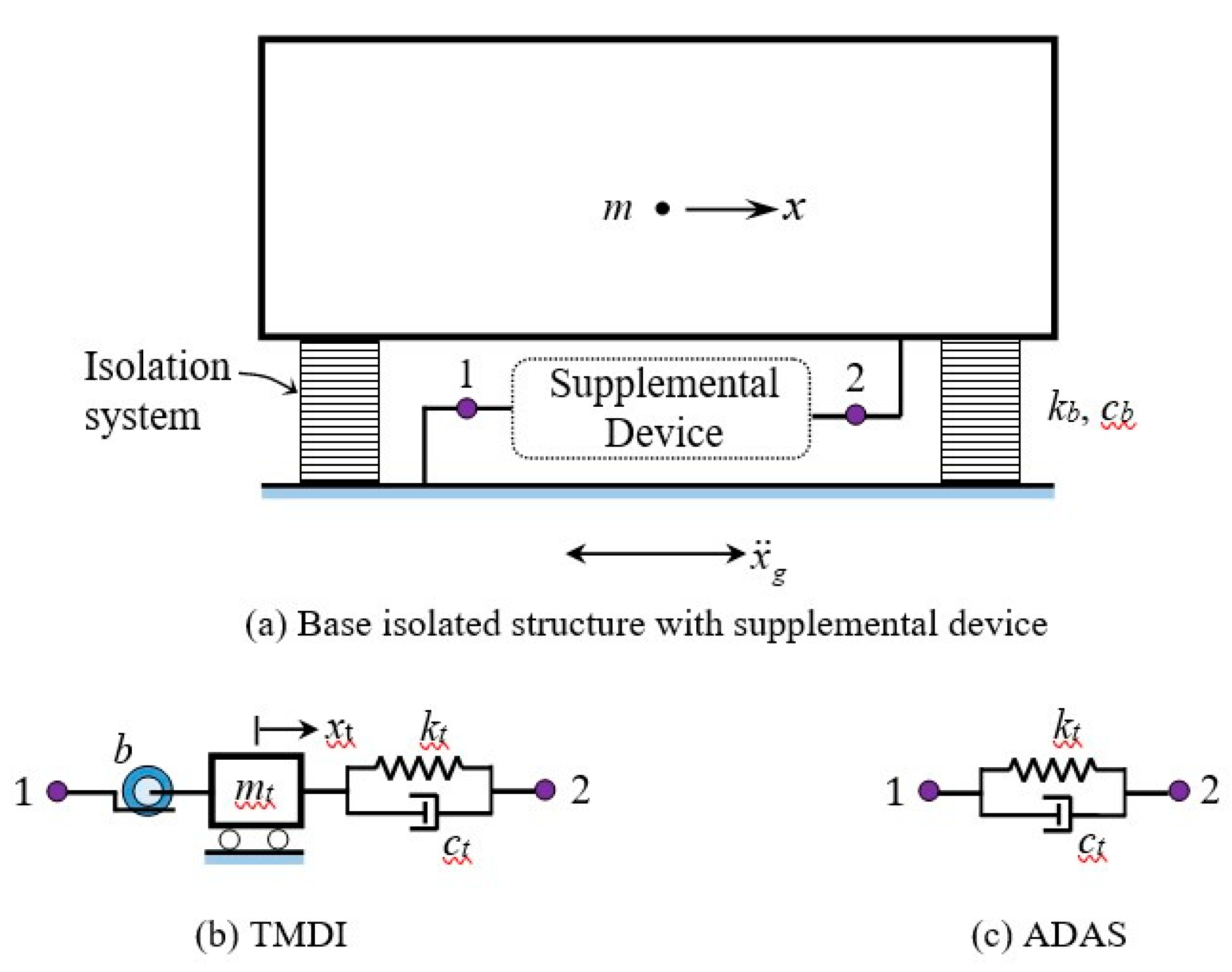
2. Base-Isolated Rigid Structure with TMDI and ADAS
3.1. Supplemental TMDI Device
3.2. Supplemental ADAS Device
3. Rigid Base-Isolated Structure with FID and FD
4. Response Under Filtered White-Noise Excitation
5. Flexible Isolated Structure Under Real Earthquakes
6. Conclusions
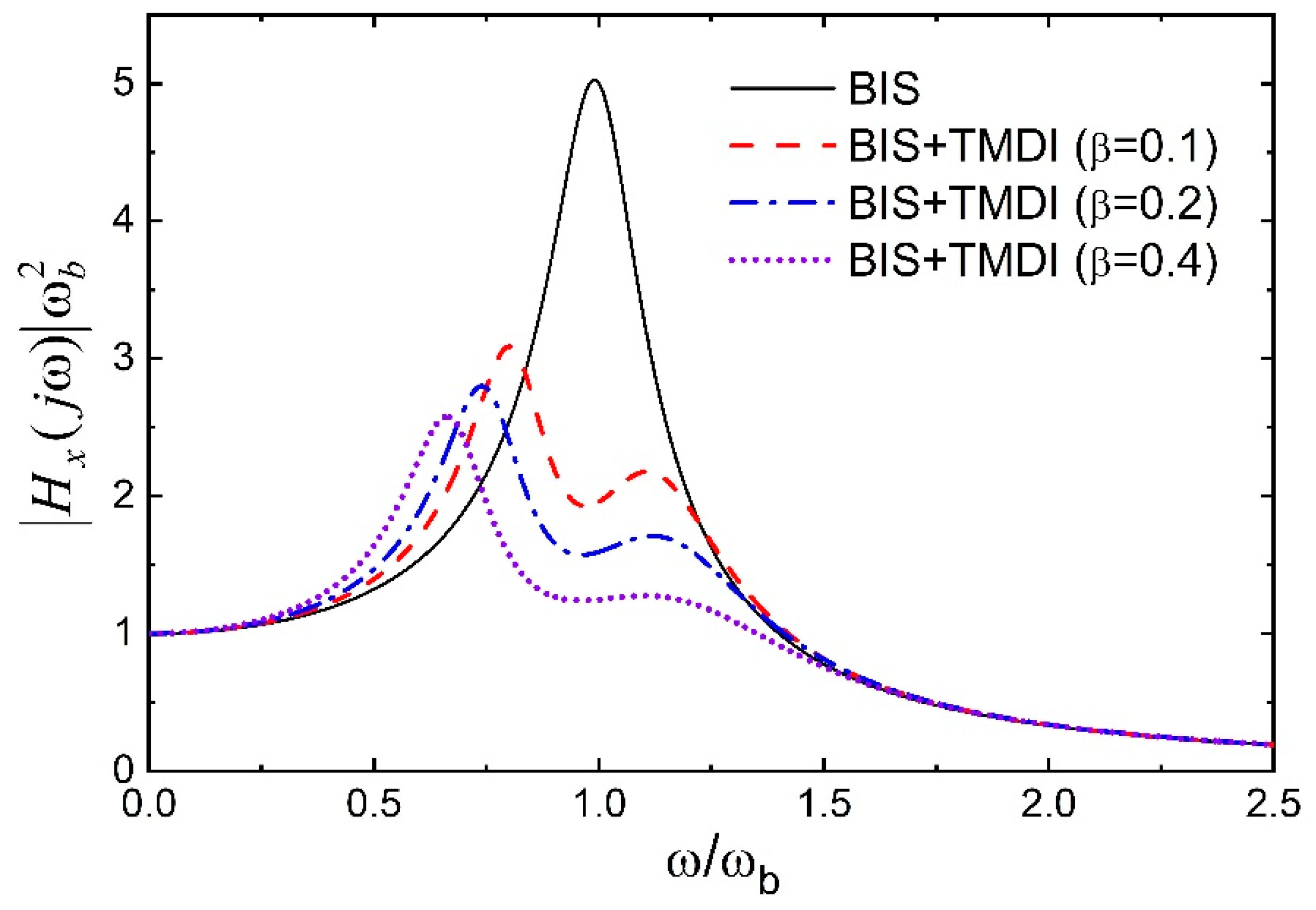
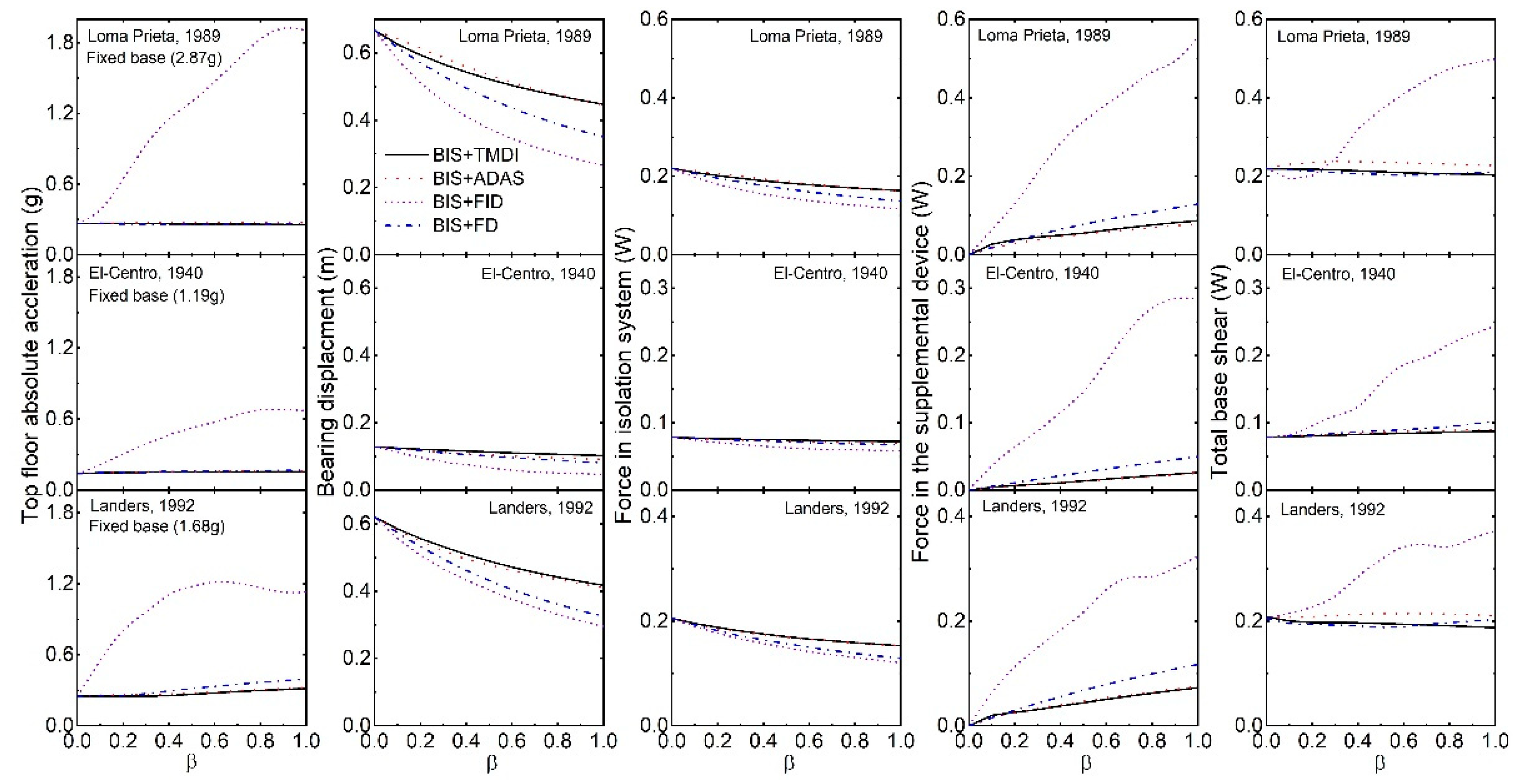
- The TMDI (especially with a sizeable inertance ratio) may not control the response of the base-isolated structure through tuning effects but controls by the added heavy damping and stiffness of its auxiliary damper under real earthquake excitation. It is recommended that the corresponding damping and stiffness (i.e., ADAS) of the TMDI be installed in parallel to the isolation device for better response control and economy.
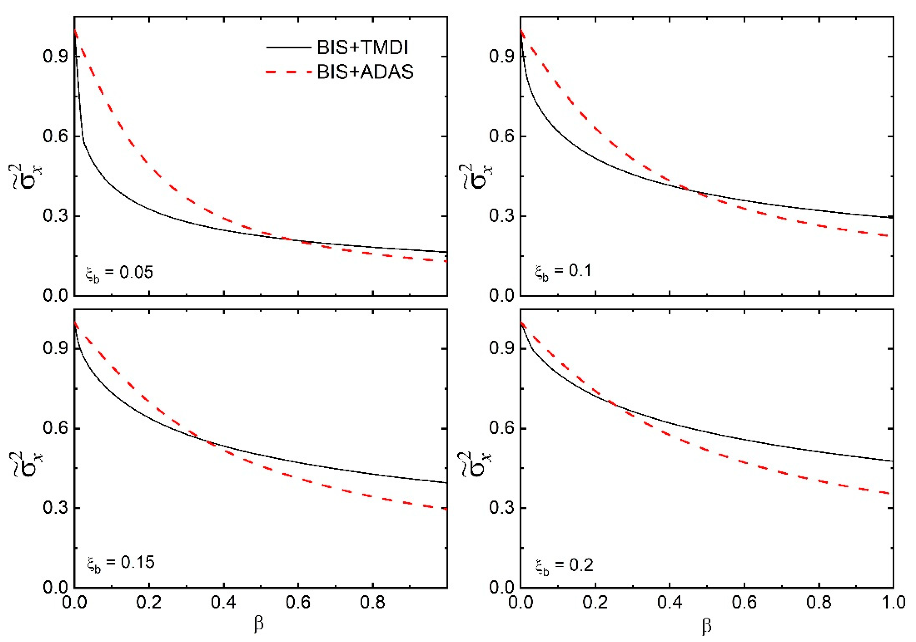
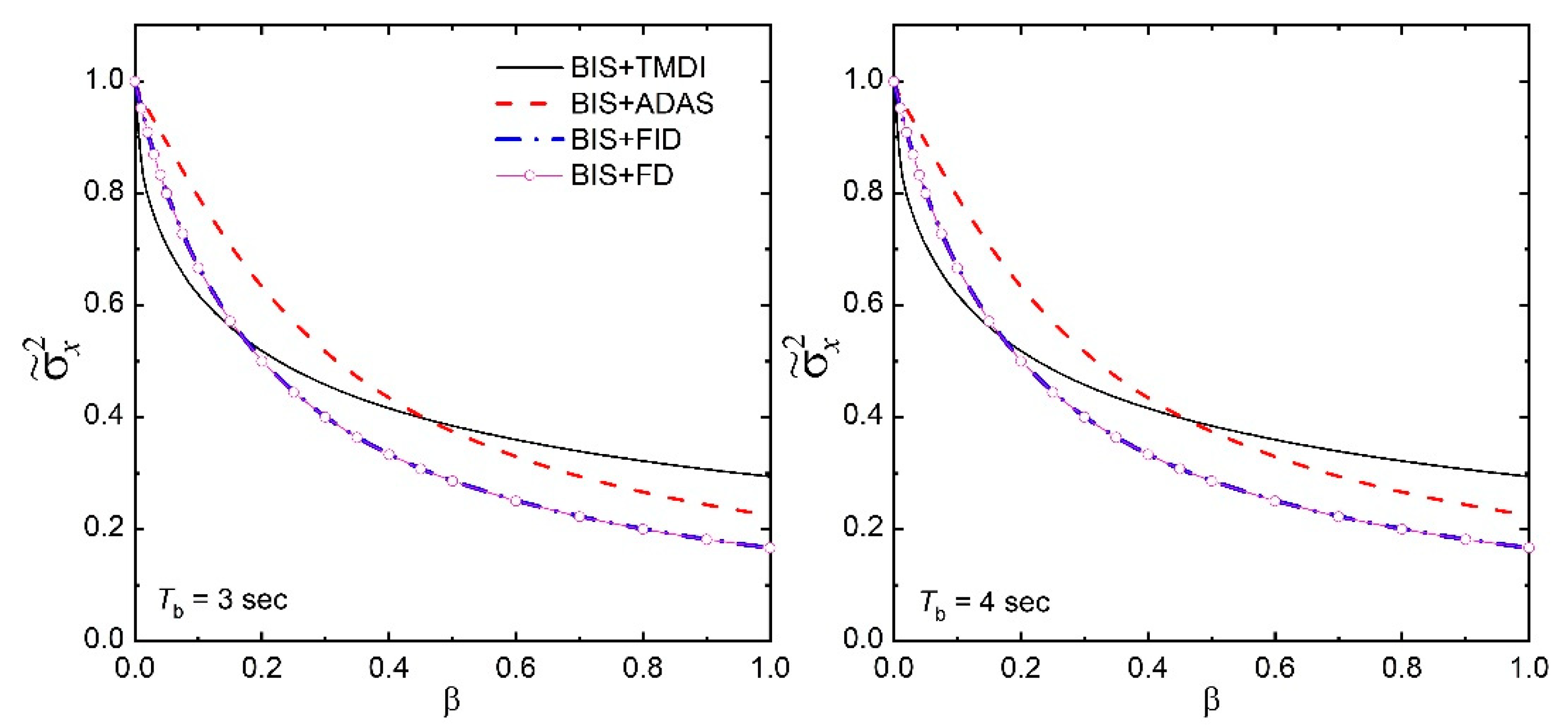
- The variance of base-isolated structures with optimal TMDI subjected to broadband earthquake excitation is higher than the corresponding ADAS for lower values of the inertance ratio. However, for the higher inertance ratio, the ADAS is superior to the TMDI in reducing the displacement variance of the base-isolated structures.
- For a broadband excitation, the displacement variance of the base-isolated structure with supplemental FID is not influenced by the inerter of the FID. The reduction in displacement is primarily happening due to the added damping of the FID. It is recommended that the FD alone can better control the response of the base-isolated structure as compared to the FID.
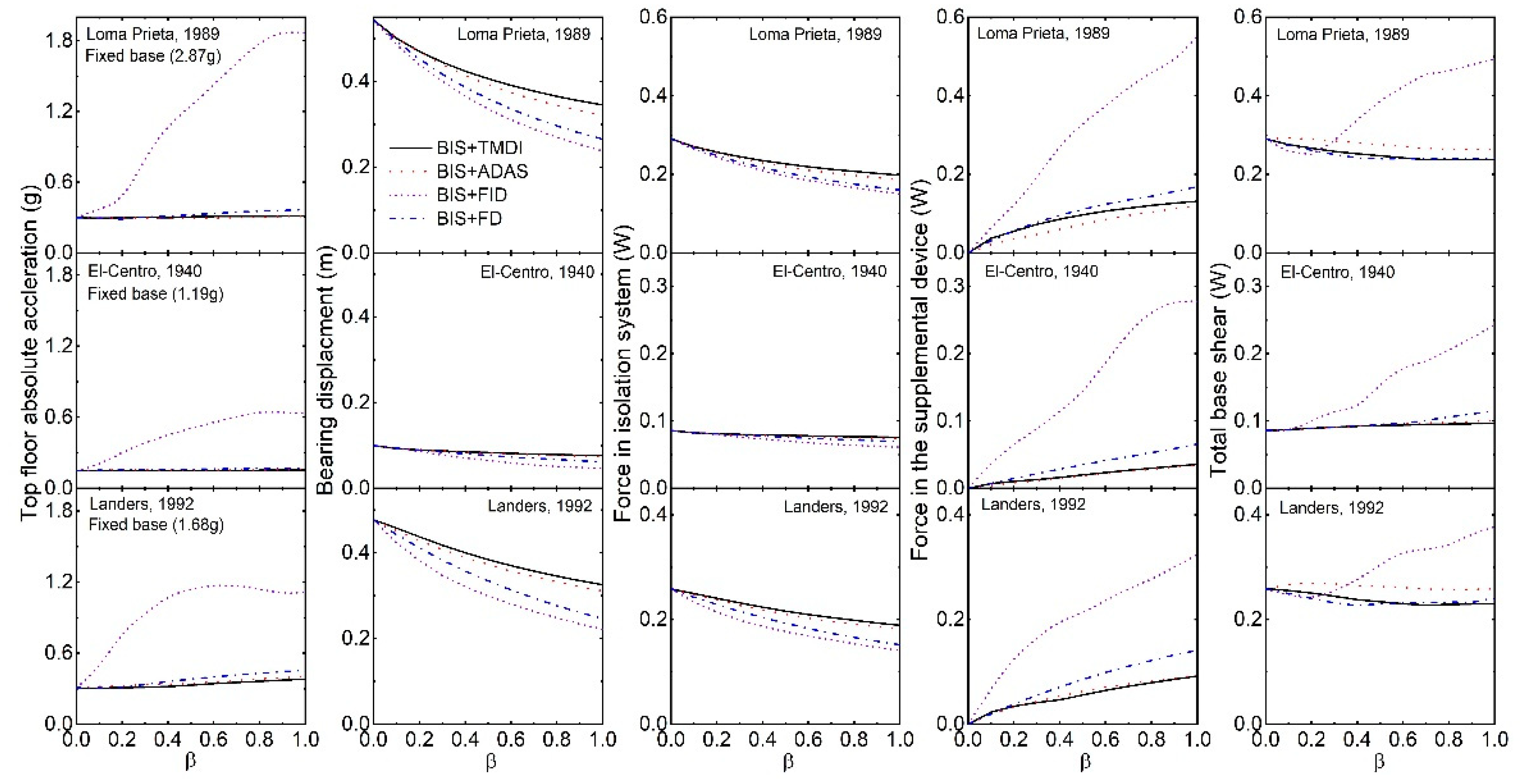
- There is a greater or comparable reduction in the base displacement of the isolated structures under real earthquake excitation by ADAS compared to the corresponding optimal TMDI. It implies that with a suitable ADAS, better control of response in the isolation system can be achieved.
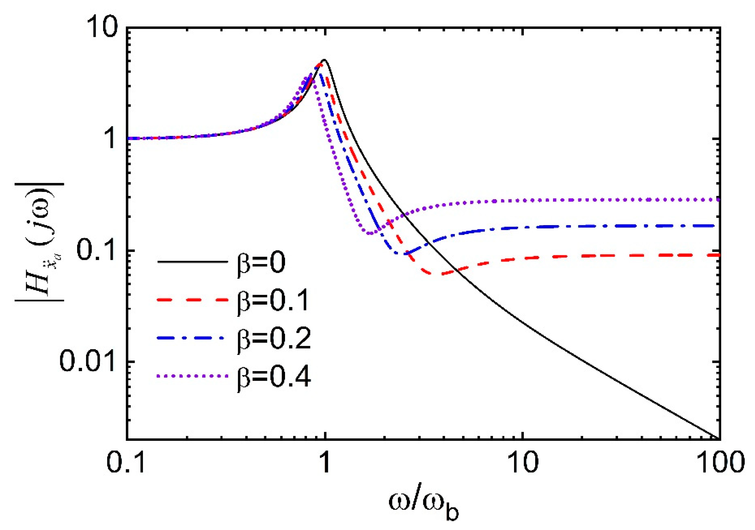
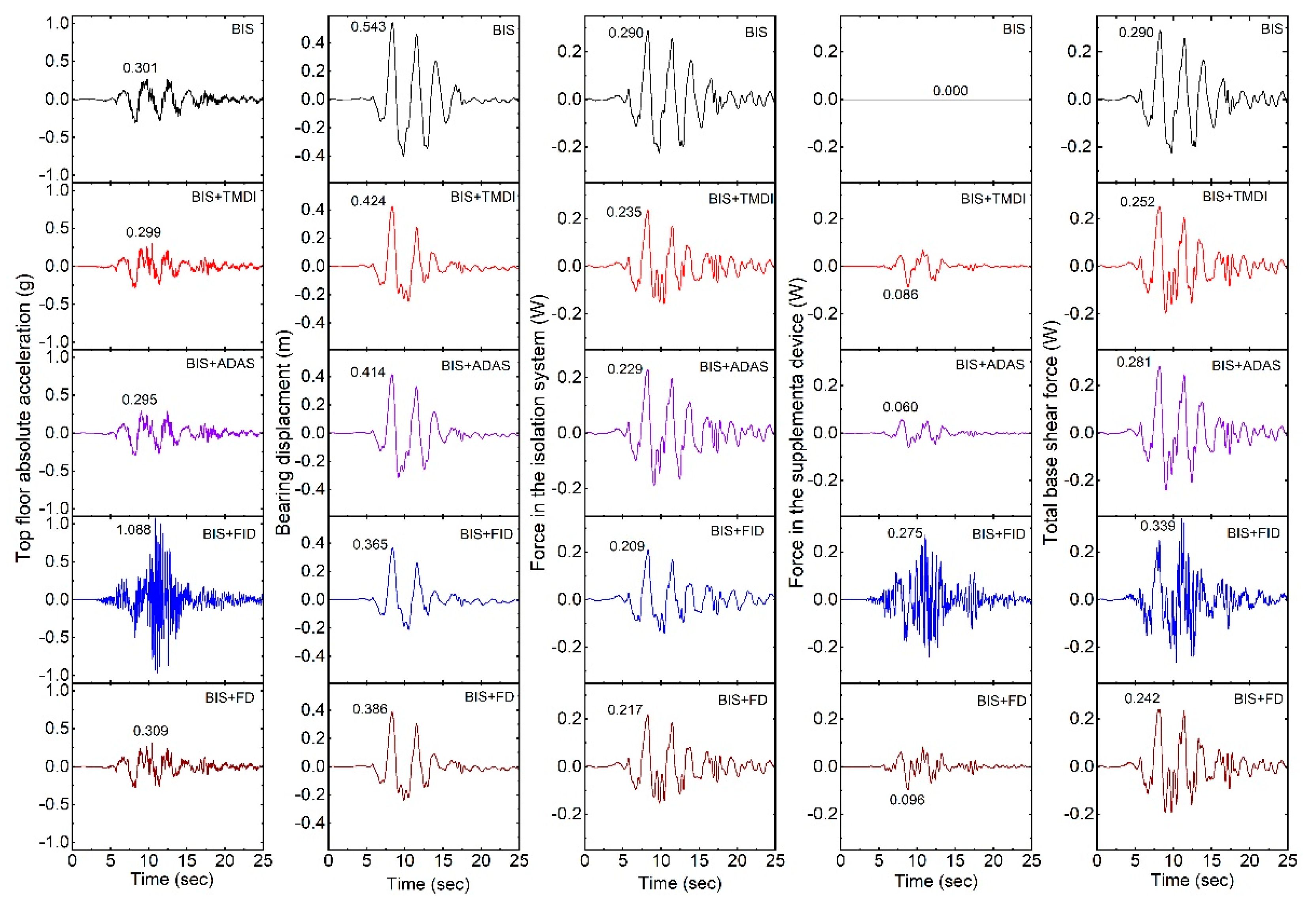
- The high-frequency components are present in the absolute structural acceleration of a base-isolated structure with FID and may have detrimental effects on high-frequency-sensitive types of equipment or secondary systems. An inerter attached to the ground and an isolated structure defeats the purpose of seismic isolation by transmitting the vibrations and increasing the base shear of the structure.
- The inerter-based supplemental devices such as TMDI (or TID) and FID (or EIMD) may not be very effective for the base-isolated structures to warrant their practical application.
Funding
Data Availability Statement
Conflicts of Interest
References
- Ma, R.; Bi, K.; Hao, H. Inerter-based structural vibration control: A state-of-the-art review. Engineering Structures 2021, 243, 112655. [Google Scholar] [CrossRef]
- Smith, M.C. Synthesis of mechanical networks: The inerter. IEEE Transactions on Automatic Control 2002, 47, 1648–1662. [Google Scholar] [CrossRef]
- De Domenico, D.; Ricciardi, G. An enhanced base isolation system equipped with optimal tuned mass damper inerter (TMDI). Earthquake Engineering and Structural Dynamics 2018, 47, 1169–1192. [Google Scholar] [CrossRef]
- De Domenico, D.; Ricciardi, G. Optimal design and seismic performance of tuned mass damper inerter (TMDI) for structures with nonlinear base isolation systems. Earthquake Engineering and Structural Dynamics 2018, 47, 2539–2560. [Google Scholar] [CrossRef]
- De Domenico, D.; Ricciardi, G. Improving the dynamic performance of base-isolated structures via tuned mass damper and inerter devices: A comparative study. Structural Control and Health Monitoring 2018, 25, e2234. [Google Scholar] [CrossRef]
- De Domenico, D.; Impollonia, N.; Ricciardi, G. Soil-dependent optimum design of a new passive vibration control system combining seismic base isolation with tuned inerter damper. Soil Dynamics and Earthquake Engineering 2018, 105, 37–53. [Google Scholar] [CrossRef]
- De Angelis, M.; Giaralis, A.; Petrini, F.; Pietrosanti, D. Optimal tuning and assessment of inertial dampers with grounded inerter for vibration control of seismically excited base-isolated systems. Engineering Structures 2019, 196, 109250. [Google Scholar] [CrossRef]
- Di Matteo, A.; Masnata, C.; Pirrotta, A. Simplified analytical solution for the optimal design of Tuned Mass Damper Inerter for base isolated structures. Mechanical Systems and Signal Processing 2019, 134, 106337. [Google Scholar] [CrossRef]
- Masnata, C.; Di Matteo, A.; Adam, C.; Pirrotta, A. Assessment of the tuned mass damper inerter for seismic response control of base-isolated structures. Structural Control and Health Monitoring 2021, 28, e2665. [Google Scholar] [CrossRef]
- Li, Y.; Li, S.; Chen, Z. Optimal design and effectiveness evaluation for inerter-based devices on mitigating seismic responses of base isolated structures. Earthquake Engineering and Engineering Vibration 2021, 20, 1021–1032. [Google Scholar] [CrossRef]
- Chowdhury, S.; Banerjee, A.; Adhikari, S. Enhanced seismic base isolation using inertial amplifiers. Structures 2021, 33, 1340–135. [Google Scholar] [CrossRef]
- Jangid, R.S. Optimum parameters and performance of tuned mass damper-inerter for base-isolated structures. Smart Structures and Systems 2022, 29, 549–560. [Google Scholar]
- Han, G.; Wu, Y.; Hou, G.; Yue, Z. Optimal design of nuclear power plants containment with tuned mass damper inerter device for earthquake loadings. Journal of Mechanical Science and Technology, 2023, 37, 5607–5621. [Google Scholar] [CrossRef]
- Li, C.; Chang, K.; Cao, L.; Huang, Y. Performance of a nonlinear hybrid base isolation system under the ground motions. Soil Dynamics and Earthquake Engineering 2021, 143, 106589. [Google Scholar] [CrossRef]
- Cao, L.; Li, C. A high performance hybrid passive base-isolated system. Structural Control and Health Monitoring 2022, 29, e2887. [Google Scholar] [CrossRef]
- Pietrosanti, D.; De Angelis, M.; Giaralis, A. Experimental study and numerical modeling of nonlinear dynamic response of SDOF system equipped with tuned mass damper inerter (TMDI) tested on shaking table under harmonic excitation. International Journal of Mechanical Sciences 2020, 184, 105762. [Google Scholar] [CrossRef]
- Pietrosanti, D.; De Angelis, M.; Giaralis, A. Experimental seismic performance assessment and numerical modelling of nonlinear inerter vibration absorber (IVA)-equipped base isolated structures tested on shaking table. Earthquake Engineering and Structural Dynamics 2021, 50, 2732–2753. [Google Scholar] [CrossRef]
- Qian, F.; Luo, Y.; Sun, H.; Tai, W.C.; Zuo, L. Optimal tuned inerter dampers for performance enhancement of vibration isolation. Engineering Structures 2019, 198, 109464. [Google Scholar] [CrossRef]
- Jangid, R.S. Optimum tuned inerter damper for base-isolated structures. Journal of Vibration Engineering & Technologies 2021, 9, 1483–1497. [Google Scholar]
- Nyangi, P.; Ye, K. Optimal design of dual isolated structure with supplemental tuned inerter damper based on performance requirements. Soil Dynamics and Earthquake Engineering 2021, 149, 106830. [Google Scholar] [CrossRef]
- Zhang, L.; Guo, M.; Li, Z.; Zhu, L.; Meng, Y. Optimal design and seismic performance of base-isolated storage tanks using friction pendulum inerter systems. Structures 2022, 43, 234–248. [Google Scholar] [CrossRef]
- Huang, X.; Hu, Z.; Liu, Y.; Nie, L. Study on seismic performance of TID-LRB hybrid control system under multi-level earthquakes. Buildings 2022, 12, 1465. [Google Scholar] [CrossRef]
- Li, J.-Y.; Lu, J.; Zhou, H. Reliability analysis of structures with inerter-based isolation layer under stochastic seismic excitations. Reliability Engineering and System Safety 2023, 235, 109222. [Google Scholar] [CrossRef]
- Tai, Y.-J.; Huang, Z.-W.; Chen, C.; Hua, X.-G.; Chen, Z.-Q. Geometrically nonlinearity analysis and performance evaluation of tuned inerter dampers for multidirectional seismic isolation. Mechanical Systems and Signal Processing 2022, 168, 108681. [Google Scholar] [CrossRef]
- Stanikzai, M.H.; Elias, S.; Matsagar, V.A.; Jain, A.K. Seismic response control of base-isolated buildings using multiple tuned mass dampers. The Structural Design of Tall and Special Buildings 2019, 28, e1576. [Google Scholar] [CrossRef]
- Stanikzai, M.H.; Elias, S.; Rupakhety, R. Seismic response mitigation of base-isolated buildings. Applied Sciences 2020, 10, 1230. [Google Scholar] [CrossRef]
- Zhao, Z.; Chen, Q.; Zhang, R.; Pan, C.; Jiang, Y. Optimal design of an inerter isolation system considering the soil condition. Engineering Structures 2019, 196, 109324. [Google Scholar] [CrossRef]
- Zhao, Z.; Zhang, R.; Jiang, Y.; Pan, C. Seismic response mitigation of structures with a friction pendulum inerter system. Engineering Structures 2019, 193, 110–120. [Google Scholar] [CrossRef]
- Sun, H.; Zuo, L.; Wang, X.; Peng, J.; Wang, W. Exact H2 optimal solutions to inerter-based isolation systems for building structures. Structural Control and Health Monitoring 2019, 26, e2357. [Google Scholar] [CrossRef]
- De Domenico, D.; Deastra, P.; Ricciardi, G.; Sims, N.D.; Wagg, D.J. Novel fluid inerter based tuned mass dampers for optimised structural control of base-isolated buildings. Journal of the Franklin Institute 2019, 356, 7626–7649. [Google Scholar] [CrossRef]
- De Domenico, D.; Ricciardi, G.; Zhang, R. Optimal design and seismic performance of tuned fluid inerter applied to structures with friction pendulum isolators. Soil Dynamics and Earthquake Engineering 2020, 132, 106099. [Google Scholar] [CrossRef]
- Jiang, Y.; Zhao, Z.; Zhang, R.; De Domenico, D.; Pan, C. Optimal design based on analytical solution for storage tank with inerter isolation system. Soil Dynamics and Earthquake Engineering 2020, 129, 105924. [Google Scholar] [CrossRef]
- Akhare, A.R. Seismic response control of base-isolated structures with fluid inerter damper. International Journal of Structural Engineering 2023, 13, 1–21. [Google Scholar] [CrossRef]
- Zhao, Z.; Hu, X.; Zhang, R.; Xie, M.; Liu, S. Advantages and design of inerters for isolated storage tanks incorporating soil conditions. Thin-Walled Structures 2024, 195, 111356. [Google Scholar] [CrossRef]
- Wang, H.; Shen, W.; Li, Y.; Zhu, H.; Zhu, S. Dynamic behavior and seismic performance of base-isolated structures with electromagnetic inertial mass dampers: Analytical solutions and simulations. Engineering Structures 2021, 246, 113072. [Google Scholar] [CrossRef]
- Lin, G.-L.; Lin, C.-C.; Li, Y.-H.; Lin, T.-T. Theoretical and experimental analysis of an electromagnetic seismic isolation system. Engineering Structures 2022, 250, 113411. [Google Scholar] [CrossRef]
- Villaverde, R. Reduction in seismic response with heavily-damped vibration absorbers. Earthquake Engineering and Structural Dynamics 1985, 13, 33–42. [Google Scholar] [CrossRef]
- Bakre, S.V.; Jangid, R.S. Optimum parameters of tuned mass damper for damped main system. Structural Control and Health Monitoring 2007, 14, 448–470. [Google Scholar] [CrossRef]
- Pietrosanti, D.; De Angelis, M.; Basili, M. Optimal design and performance evaluation of systems with Tuned Mass Damper Inerter (TMDI). Earthquake Engineering and Structural Dynamics 2017, 46, 1367–1388. [Google Scholar] [CrossRef]
- Prakash, S.; Jangid, R.S. Optimum parameters of tuned mass damper-inerter for damped structure under seismic excitation. International Journal of Dynamics and Control 2022, 10, 1322–1336. [Google Scholar] [CrossRef]
- Makris, N. Rigidity - plasticity - viscosity: Can electrorheological dampers protect base-isolated structures from near-source ground motions? Earthquake Engineering and Structural Dynamics 1997, 26, 571–591. [Google Scholar] [CrossRef]
- Swift, S.J.; Smith, M.C.; Glover, A.R.; Papageorgiou, C.; Gartner, B.; Houghton, N.E. Design and modelling of a fluid inerter. International Journal of Control 2013, 86, 2035–2051. [Google Scholar] [CrossRef]
- Liu, X.; Jiang, J.Z.; Titurus, B.; Harrison, A. Model identification methodology for fluid-based inerters. Mechanical Systems and Signal Processing 2018, 106, 479–494. [Google Scholar] [CrossRef]
- Wagg, D.J.; Pei, J.-S. Modeling a helical fluid inerter system with time-invariant mem-models. Structural Control and Health Monitoring 2020, 27, e2579. [Google Scholar] [CrossRef]
- Roberts, J.B.; Spanos, P.D. Random vibration and statistical linearization. Wiley: Chichester, UK, 1990. [Google Scholar]
- Kanai, K. Semi-empirical formula for the seismic characteristics of the ground. Bulletin of the Earthquake Research Institute 1957, 35, 309–325. [Google Scholar]
- Tajimi, H. A statistical method of determining the maximum response of a building structure during an earthquake. Proc. of 2nd World Conference on Earthquake Engineering 1960, 11, 781–798. [Google Scholar]
- Kelly, J.M. Earthquake-resistant design with rubber, 2nd ed.Springer-Verlag: London, UK, 1997. [Google Scholar]
- Chopra, A.K. Dynamics of Structures: Theory and Applications to Earthquake Engineering. 5th Edn.; Pearson, NJ, 2017.
- Li, L.; Liang, Q. Effect of inerter for seismic mitigation comparing with base isolation. Structural Control and Health Monitoring 2019, 26, e2409. [Google Scholar] [CrossRef]
- Makris, N.; Moghimi, G. Displacements and forces in structures with inerters when subjected to earthquakes. Journal of Structural Engineering 2019, 145, 04018260. [Google Scholar] [CrossRef]
- Jangid, R.S. Seismic performance of supplemental inerter and spring with on-off effects for base-isolated structures. Journal of Infrastructure Intelligence and Resilience 2023, 2, 100038. [Google Scholar] [CrossRef]
- Jangid, R.S. Seismic performance of a clutched inerter for structures with curved surface sliders. Structures 2023, 49, 44–57. [Google Scholar] [CrossRef]
- Gao, H.; Xing, C.; Wang, H.; Li, J.; Zhang, Y. Performance improvement and demand-oriented optimum design of the tuned negative stiffness inerter damper for base-isolated structures. Journal of Building Engineering 2023, 63, 105488. [Google Scholar] [CrossRef]
- Islam, N.U.; Jangid, R.S. Optimum parameters and performance of negative stiffness and inerter based dampers for base-isolated structures. Bulletin of Earthquake Engineering. 2023, 21, 1411–1438. [Google Scholar] [CrossRef]


Disclaimer/Publisher’s Note: The statements, opinions and data contained in all publications are solely those of the individual author(s) and contributor(s) and not of MDPI and/or the editor(s). MDPI and/or the editor(s) disclaim responsibility for any injury to people or property resulting from any ideas, methods, instructions or products referred to in the content. |
© 2024 by the author. Licensee MDPI, Basel, Switzerland. This article is an open access article distributed under the terms and conditions of the Creative Commons Attribution (CC BY) license (https://creativecommons.org/licenses/by/4.0/).


