1. Introduction
Liquid-liquid heterogeneous flow process was widely applied in the chemical industry [
1]. An in-depth analysis of droplet deformation and breakup contributed to the design and optimization of dispersed multiphase flows [
2]. The disruptive shear stress can be found at the jet boundary vortices. The droplet deformation or breakup was caused by the shear stress, and the mass transfer between the phases was determined by droplet surface area [
3,
4,
5]. To predict and evaluate the separation or mixing processes of multiphase flow, the droplet deformation mechanism was investigated for exploring the mass transfer processes, such as liquid-liquid heterogeneous phase mixing and separation.
When a droplet traversed a vortex, the uneven energy was transferred to the droplet surface from the vortex, which resulted in the deformation or breakup of droplet. Andersson developed an energy criterion to predict droplet breakup, which occurred when the turbulent kinetic energy of vortex attained a critical value. The energy-critical value was calculated by the interfacial energy of mother drop and the breakup criterion was defined as the interfacial energy increase for drop deformed complex [
6]. Andersson revealed that the deformed drops attained the maximum value of interfacial energy before breakup, and more energy was required to be transferred from the turbulent vortices for breakup [
7,
8]. The drop breakup in the turbulent flow was mainly caused by the turbulent pressure fluctuation mechanism when the Ohnesorge number was less than 0.01. Chen et al. proposed that the drop breakup criteria depended on the degree of surface deformation prior to breakup, and the relationship between turbulent eddies and drop breakup was established and quantified [
9]. Han et al. proposed a theoretical model based on the theories of isotropic turbulence that the drop breakup was based on interfacial energy density increase [
10]. As mentioned above, the interfacial energy played a key role in the study of droplet deformation and breakup. The reason for drop breakup was that droplets were subject to large-scale deformations prior to breakup, and the surface oscillation was obvious.
Experimental study of the droplet deformation mechanism was difficult and the deformation process can only be studied by monitoring the drop behavior. However, Computational fluid dynamics (CFD) simulation offered a solution to overcome these obstacles. The drop dynamic characteristic in multiphase flow systems was investigated by large eddy simulation (LES) [
11,
12,
13,
14], and volume of fluid (VOF) method was usually used to obtain the interface deformation due to the complexity of interface topology [
15,
16]. A combination of LES and VOF was used to research the interaction between jet and drop and predicted the complex interface of deformed droplets [
17,
18,
19,
20,
21]. To prevent numerical diffusion of density and viscosity at the drop interface, the Geo-Reconstruct scheme was used to reconstruct the grid during computation. Additionally, the dynamic adaptation meshing technique was applied to manage mesh encryption at the liquid-liquid heterogeneous interface [
22,
23,
24,
25]. The above numerical simulation approach has been recognized as a classic reference to study the droplet dynamic characteristic, as studied by Charin [
26]. Although Charin's study focused on the rising droplet, the behavior of single droplet dynamics in the continuous-phase was similar. The dynamic adaptation mesh refinement technique promoted the study of LES-VOF numerical simulation in droplet deformation and breakup.
Our previous research found that the wall jet flow was affected by the curvature radius of concave-wall in two ways, the jet spread in radial direction shrank [
27] and the instability at the jet boundary increased [
28]. Within the possible studies in concave-wall jet, the intrinsic and extrinsic factors of droplet deformation were the particular interest to this paper. The LES-VOF model was used to study the deformation mechanism of carbon tetrachloride (CCl
4) droplet in the concave-wall jet with water as the continuous-phase. The droplet dynamic characteristic was investigated based on the centrifugal force field which was created by the concave-wall jet with various curvature radii.
2. Numerical Simulation
2.1. Physical Models and Materials
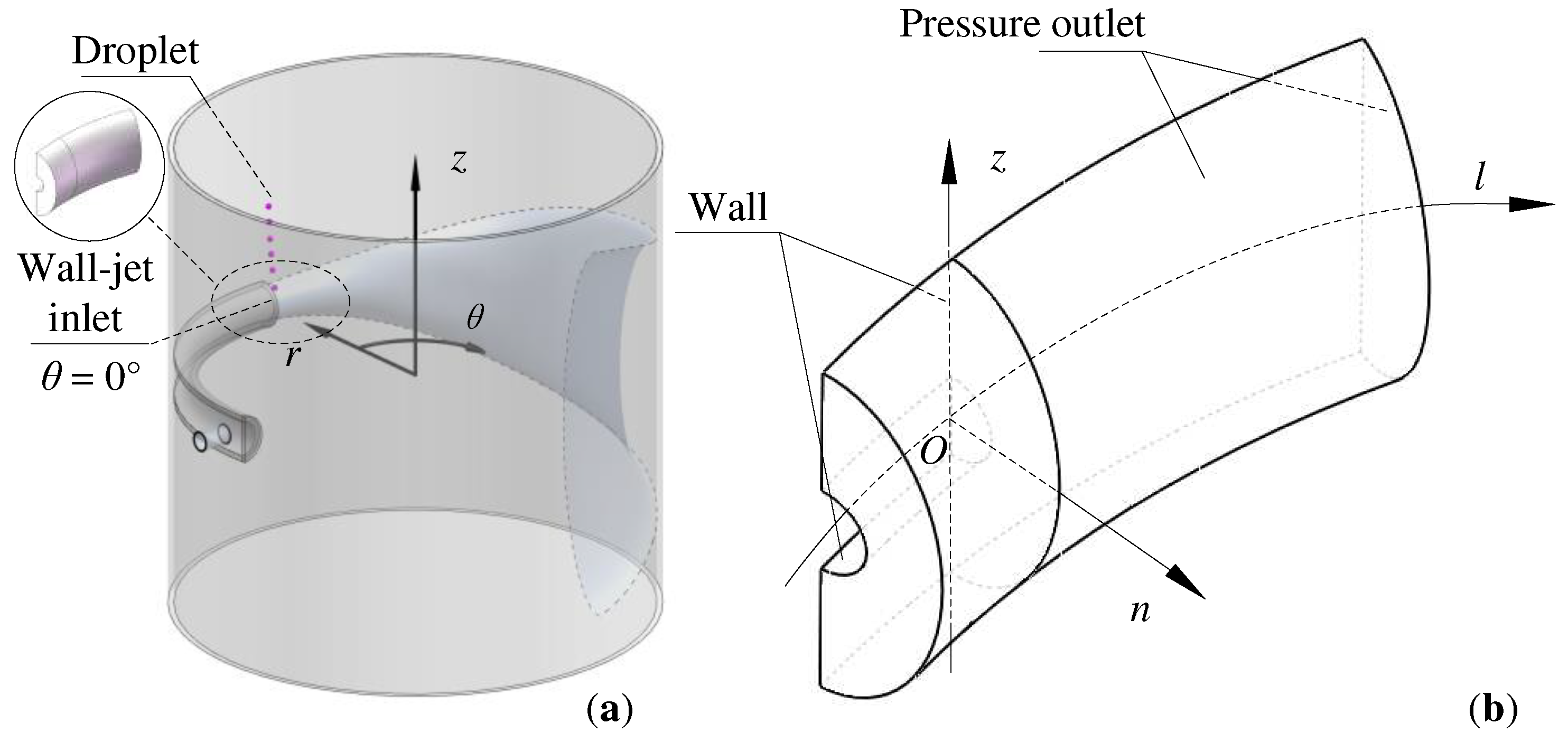
Figure 1a depicts the falling process of a CCl
4 droplet in a vertical cylinder filled with water. The jet inlet section was made into a semicircular shape with a radius of 15 mm (
R = 15 mm), where
θ = 0° was the circumferential coordinate of jet inlet. Since the study focused on the localized flow near the concave-wall at the jet inlet, the annular channel at -15° <
θ < 35° was retained as the study domain considering the jet inlet entraining effect, which is depicted in
Figure 1b. The coordinate system in
Figure 1b was converted from the cylindrical coordinate system in
Figure 1a with the following conversion equation:
Where
l is the streamwise coordinate,
n is the wall-normal coordinate, and
R0 is the curvature radius of concave-wall.
2.2. Numerical Simulation Method and Boundary Conditions
The numerical framework was implemented in Ansys Fluent 16.2, the unsteady turbulent flow was computed by three-dimensional double-precision implicit solver. LES and VOF models were coupled to explore the fluid dynamics of CCl
4 drop deformation in the concave-wall jet under purified water conditions. Physical properties of the binary system are described in
Table 1. The VOF model relied on the discrete-phase volume fraction
α, the cell was situated at the heterogeneous interface when 0 <
α < 1, indicating that the volume fraction of CCl
4 was
α, and that of water was 1-
α. The body forces were treated refer to the continuum surface force model [
29].
PISO algorithm was used to deal with pressure-velocity coupling and PRESTO! scheme was applied for the pressure discretization in large eddy simulation. The momentum equation was discretized by the Bounded Central Differencing scheme. Geo-reconstruct scheme was utilized to track the phase interface in the computing cell. The dynamic adaptive approach was employed to refine the droplet boundary mesh.
Table 1.
Physical parameters of continuous-phase (Water) and discrete-phase (CCl4) at T = 293.15 K.
Table 1.
Physical parameters of continuous-phase (Water) and discrete-phase (CCl4) at T = 293.15 K.
| Continuous-phase |
Value |
Discrete-phase |
Value |
| Density ρ/kg·m−3
|
998.2 |
Density ρp/kg·m−3
|
1595.0 |
| Viscosity/m2·s-1
|
1.003×10⁻⁶
|
Viscosity/m2·s-1
|
9.69×10⁻⁴
|
| Jet inlet velocity uin/m·s−1
|
0.55 |
Droplet diameter dp/mm |
5.6 |
| Interfacial tension σ/mN·m-1
|
45.7 |
| Gravity g/m·s-2
|
-9.81 |
The boundary conditions were as follows: Jet inlet was set as velocity-inlet (uin), while the outlet was defined as pressure-outlet with a gauge pressure of 0. The solid wall was smooth and non-slip. A gravitational field with a magnitude of -9.81 m∙s-2 in the Z-direction was applied. In terms of the discrete-phase initialization, the CCl4 droplet was defined as a sphere for falling into the jet. The droplet center was arranged at z = 40 mm, n = 5 mm and l = 10 mm from jet inlet. The time-step size was set as 10 μs unsteady calculation and 200 computing steps was the maximum value to ensure convergence limited to 10-5 in each time-step.
2.3. Mesh Division and Independence Analysis
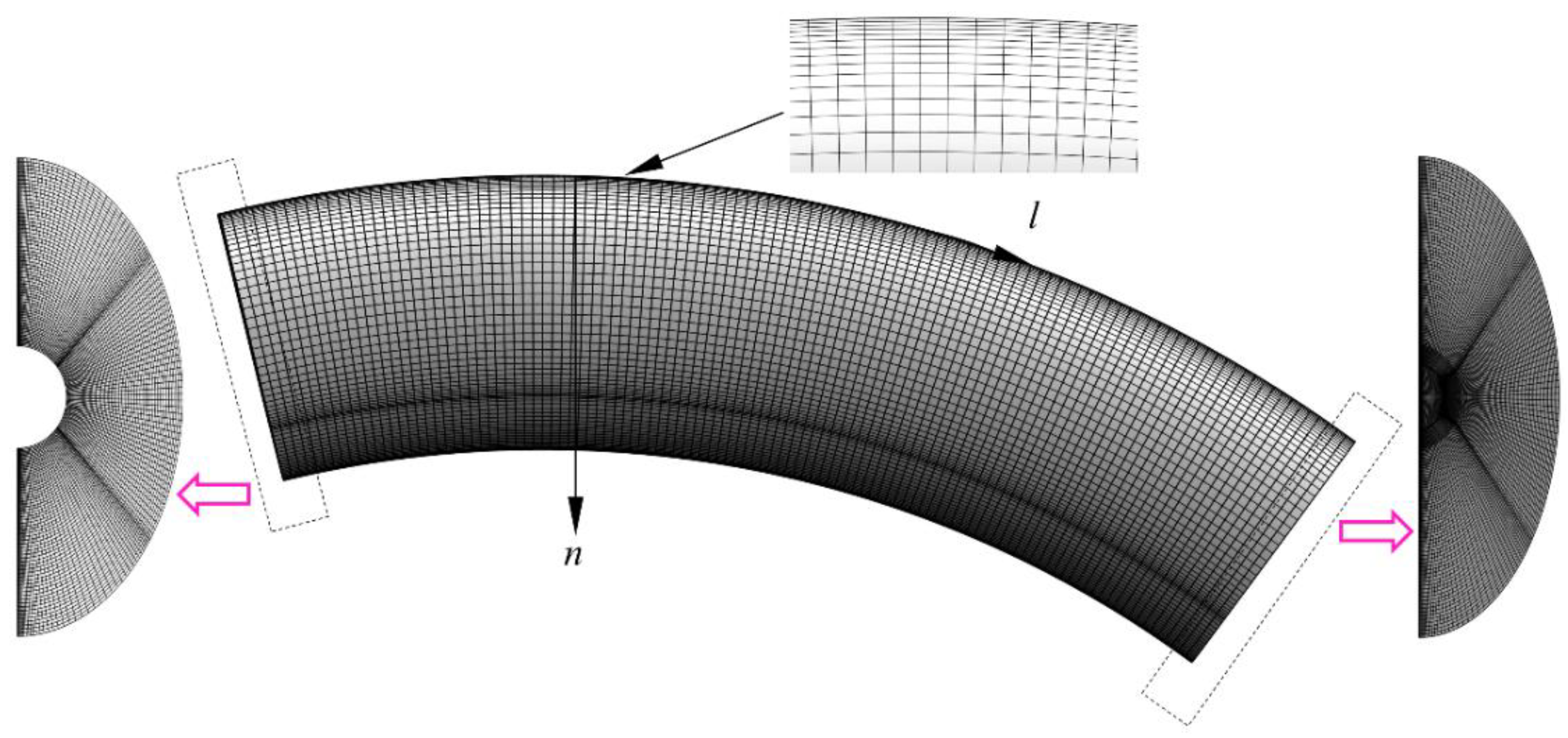
To obtain a three-dimensional hexahedral grid, the computational domain was divided into two parts bounded by the jet inlet section. The flow domain in the study was meshed by ICEM software with refinement near the concave-wall, as illustrated in
Figure 2. The mesh independence analysis was performed in two steps: (i) the various grid densities were employed for the same computational domains (Grid-1, Grid-2, Grid-3), and (ii) the various computational domain sizes were used for the same grid density condition (Grid-2, Grid-4, Grid-5). Due to the flow characteristic of concave-wall jet, the droplet dynamics were greatly impacted by the spanwise size of computational domain, and the effect of wall-normal size was smaller. Therefore, the spanwise sizes of Grid-2, Grid-4, and Grid-5 were adjusted to 120 mm, 80 mm, and 200 mm respectively, while the wall-normal sizes remained the same.
The five grid schemes were applied to the case of a drop with
dp = 5.6 mm,
uin = 0.55 m∙s
-1, and
R0 = 300 mm where the droplet surface area (
Ap) was obtained from multi-time computational results. Maximum values of
Ap were compared at the period of
t = 0.00 ~ 0.30 s, and the specific simulation results were presented in
Table 2. The simulation data indicates that the droplet maximum surface areas of Grid-2, Grid-3 and Grid-5 were similar when the identical computational settings were assessed. The
Ap deviation of Grid-2 and Grid-3 was only 5.1%, while that of Grid-2 and Grid-5 was 4.7%. Considering the accuracy of simulated data, the computational domain setting and meshing scheme of Grid-2 were selected to save computational time and storage space. The total number of meshes ranged from 1005855-1061886 for different structure models, and the mesh size near the concave-wall was 0.05 mm.
Figure 2.
Three-dimensional hexahedral mesh employed for simulations.
Figure 2.
Three-dimensional hexahedral mesh employed for simulations.
2.4. Experimental Validation
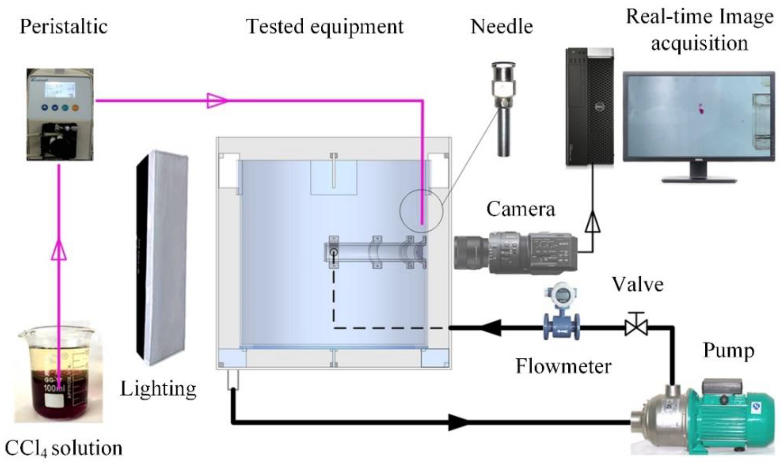
Our team provided an experimental system utilized to capture images of the dynamic process of droplet deformation and breakup in a concave-wall tangential jet [
30].
Figure 3 illustrated the experimental setup which was consisted with three components: water jet system, CCl
4 droplets generator and real-time image acquisition system. A lighting device was installed opposite to the camera to obtain clear images (see
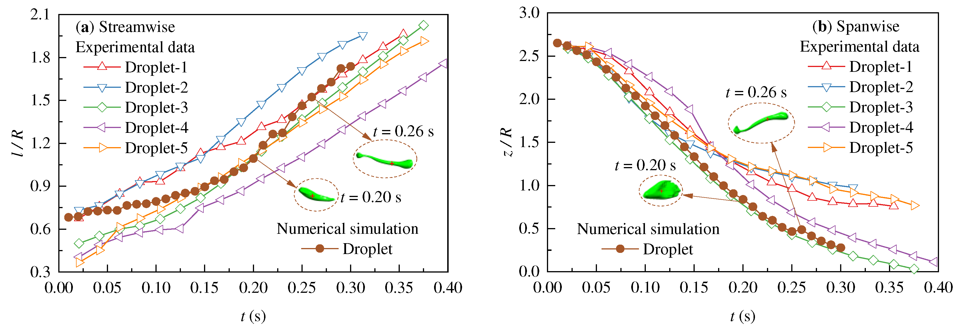
Figure 3). The numerical simulations performed in this paper were validated by data in which five droplets were obtained from the experiments, which proved the precision of simulation scheme in foretelling the process of droplet deformation and breakup.
Figure 4 offers a comparison of the drop centroid position between the experimental data and simulation data using the LES-VOF method. The simulation result demonstrated similar trends to the experimental data concerning the relative positions of the drop centroid position and the jet inlet. All simulated data existed within the experimental data range, indicating the possibility of using the numerical simulation scheme to describe the dynamic behavior of droplet passing through the concave-wall jet.
3. Results and Analysis
With the decreasing of the concave-wall curvature radius R0, the centrifugal force increased in the jet region and the jet expansion shrank along the wall-normal direction. The jet boundary flow was significantly influenced and droplet behaviors in the jet boundary were inevitably affected by R0 for the heterogeneous phase flow.
3.1. Normalized Interfacial Energy
Studies showed that droplets interact with vortices in the flow field and the phase-interface contact area of droplet increased by consuming vortex energy [
31]. In the concave-wall jet, the droplet was mainly stretched along the streamwise, and the heterogeneous interface area and interfacial energy increased. The interfacial energy was defined as the product of the interfacial tension coefficient and the instantaneous interfacial area. The normalized interfacial energy
γ was a dimensionless parameter of droplet deformation.
Where
Ap0 is the droplet area at the initial time
t = 0 s, the droplet was spherical, and
γ = 1.
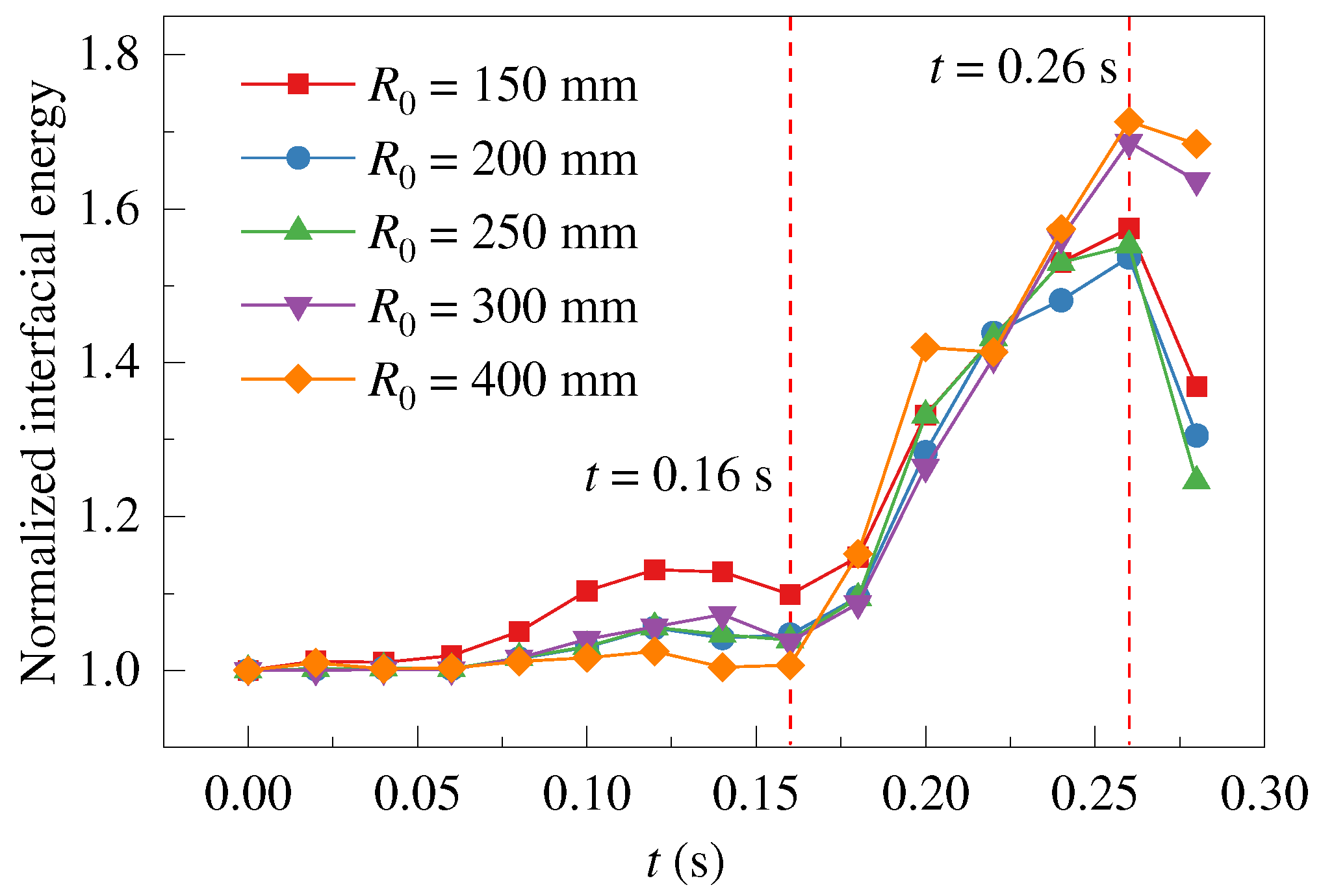
To investigate the effects of the concave-wall curvature radius on droplet deformation and breakup, the normalized interfacial energy of droplet was analyzed as shown in
Figure 5. It is seen that the droplet fell outside of the jet at
t ≤ 0.16 s, the interfacial area of droplet was decreased as
R0 increased. At
t = 0.16 s, the
γ-value of
R0 = 400 mm decreased by 8.4% compared to that of
R0 = 150 mm. The interfacial area increased rapidly at
t = 0.16 ~ 0.25 s, and the breakup occurred at
t ≈ 0.26 s. The maximum increment of the interfacial energy was 53.7% (
R0 = 200 mm) ~ 71.4% (
R0 = 400 mm), which translated to
γmax = 1.54 ~ 1.71. These agreed with the experimental estimate 1.26 <
γ < 1.92 for droplet deformation before breakup [
8]. After
t > 0.26 s, the mother droplet broke into daughter droplets, causing the total interfacial area to significantly decrease due to the shrinkage of the daughter droplets into an approximate ellipsoidal shape after breakage.
3.2. Deformation Properties
Both shear stress and normal stress were the keys to the droplet breakup in turbulent flow [
8]. When a droplet enters the jet boundary, the shear rate around the drop significantly changes. The concave-wall curvature radius played a crucial role in the distribution of shear stress and centrifugal force at the jet boundary, directly affecting on the droplet dynamic behaviors. To gain insight into the droplet deformation properties as affected by the centrifugal force field, we analyzed of the droplet deformation dimensions along the streamwise
Ll and wall-normal direction
Ln.
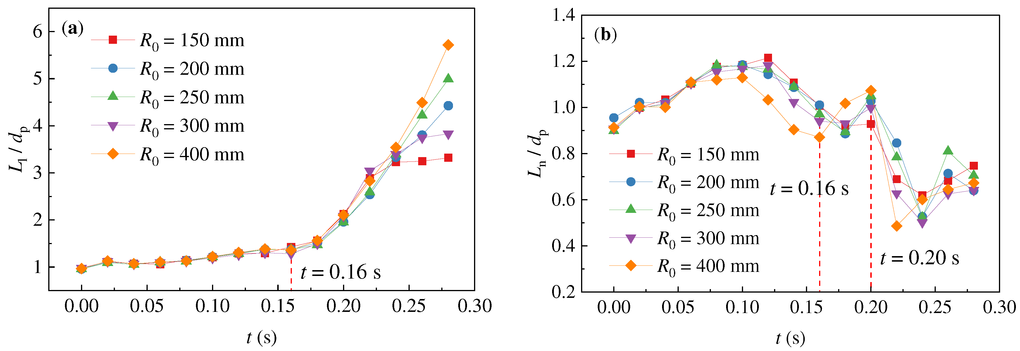
Figure 6 shows the dimensionless size analysis based on the droplet’s initial diameter
dp.
It can be seen that the droplet stretching processes were similar in different centrifugal force fields based on
R0.
Figure 6a shows the droplet deformation along the streamwise, and the deformation rate was accelerated when the droplet entered the jet region after
t = 0.16 s. At
t = 0.20 ~ 0.26 s,
Ll of droplet was longer with the increasing
R0. In
Figure 6b, droplets were stretched
Ln/
dp = 0.9 ~ 1.2 at
t ≤ 0.16 s. At
t = 0.16 ~ 0.20 s, the droplet entered the jet boundary, the droplet size was close to
Ln/
dp ≈ 1.0. At
t ≥ 0.20 s, while the droplet was in the concave-wall jet, the droplet rapidly shrank along the wall-normal direction under the centrifugal force.
Figure 6.
Dimensionless size of droplet along (a) the streamwise and (b) wall-normal direction.
Figure 6.
Dimensionless size of droplet along (a) the streamwise and (b) wall-normal direction.
From
Figure 5 and
Figure 6, the results were summarized in that the droplet deformation process was divided into three stages. Outside the jet, the droplets were only subjected to the flow resistance of continuous-phase, and the spreading deformation occurred along the streamwise and wall-normal direction (
Ln <
Ll). Within the jet boundary, the shear rate in the streamwise was much greater than the wall-normal direction, and the droplets were stretched along the streamwise, while
Ln ≈
dp. In the core area of potential flow, the centrifugal force field caused the droplets to approach the concave-wall, and the droplets contracted along the wall-normal direction by the wall restricted. When
Ln <<
Ll, the drop broke up into multiple daughter droplets. Therefore, this study focused on the droplet in the jet boundary at
t = 0.20 s and investigated the influence of the concave-wall curvature on the droplet deformation mechanism.
3.3. Q-Criterion Based Vortex Analysis of a Concave-Wall Jet
The Q-criterion was a well-established method for identifying vortices. Constantinescu et al. suggested that the second invariant of the velocity gradient tensor was defined as the quantity
Q, vortices can be pointed when
Q > 0 [
32]. To understand the droplet deformation process in the concave-wall jet, the Q-criterion was used to accurately locate the core of vortices.
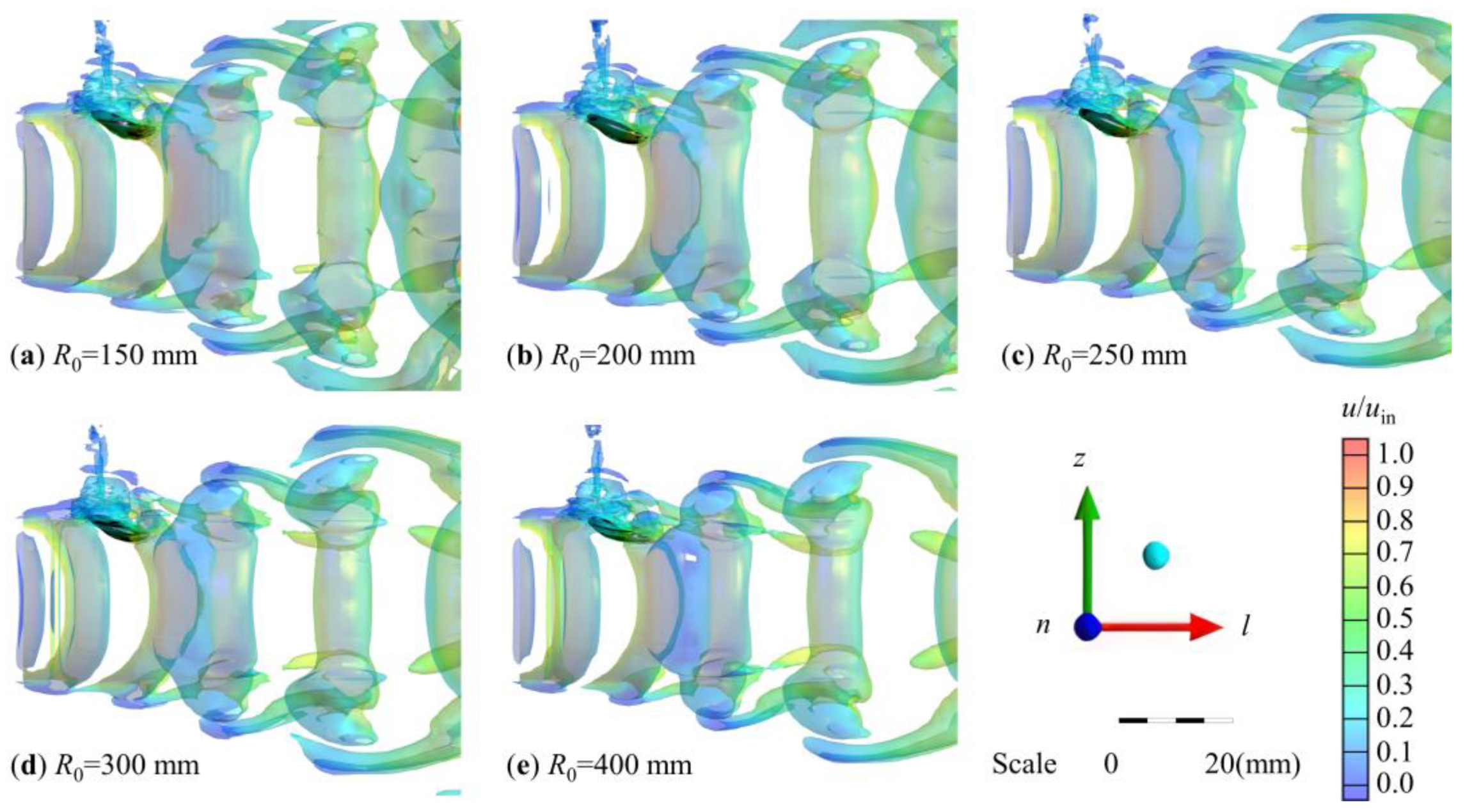
Figure 7 shows the flow field at the critical moment (
t = 0.20 s) when the droplet entered the jet boundary. Within this study, a
Q threshold of 53 s
-2 (Level = 0.01) was selected to describe vortices, vortices with varying sizes can be found in the concave-wall jet boundary. The droplet was visualized using the isosurface of volume fraction of CCl
4 α = 0.5 and colored black to indicate its location and shape.
According to the Q-criterion, we can observe the vortices generated at the jet boundary. It can be seen that the continuous-phase flow field was influenced by the concave-wall curvature radius. With an increased R0, the region of Q > 53 s-2 reduced, the distance between neighboring vortices grew larger, and the influence range of vortices became narrower along the spanwise. The dimensionless velocity parameter u/uin revealed that the u/uin > 0.5 regions shrank both streamwise and spanwise, and the continuous-phase velocity in vortices decreased. This also indicated that the vortex strength decreased as the concave-wall curvature radius increased.
At t = 0.20 s, the droplet exhibited a unique "high left and low right" shape and a part of the droplet far from the jet inlet entered the jet boundary region. The droplet swiftly spread out and formed a thin sheet that integrated closely to the jet boundary region, it underwent the spreading deformation process along the streamwise in the jet boundary. As R0 increased, the stretching length along the streamwise grew due to the decrease in centrifugal force, while the sheet thickness along the spanwise remained unchanged. Interestingly, the droplet fell and triggered the formation of vortices in the surrounding fluid, and the strength of these vortices around the droplet grew in proportion to R0, as indicated by the increasing u/uin value.
Figure 7.
Droplet deformation and interaction with jet boundary vortices at t = 0.20 s based on different concave-wall curvature radii. (a) R0 = 150 mm; (b) R0 = 200 mm; (c) R0 = 250 mm; (d) R0 = 300 mm; (e) R0 = 400 mm. The droplet was colored black and vortices were colored by velocity magnitude.
Figure 7.
Droplet deformation and interaction with jet boundary vortices at t = 0.20 s based on different concave-wall curvature radii. (a) R0 = 150 mm; (b) R0 = 200 mm; (c) R0 = 250 mm; (d) R0 = 300 mm; (e) R0 = 400 mm. The droplet was colored black and vortices were colored by velocity magnitude.
3.4. Pressure Field Distribution Inside the Droplet
Droplet deformation was a form of energy transfer, and Wang and his team discovered that there was a direct correlation between the additional hydrostatic energy consumption and the droplet stretching and deformation [
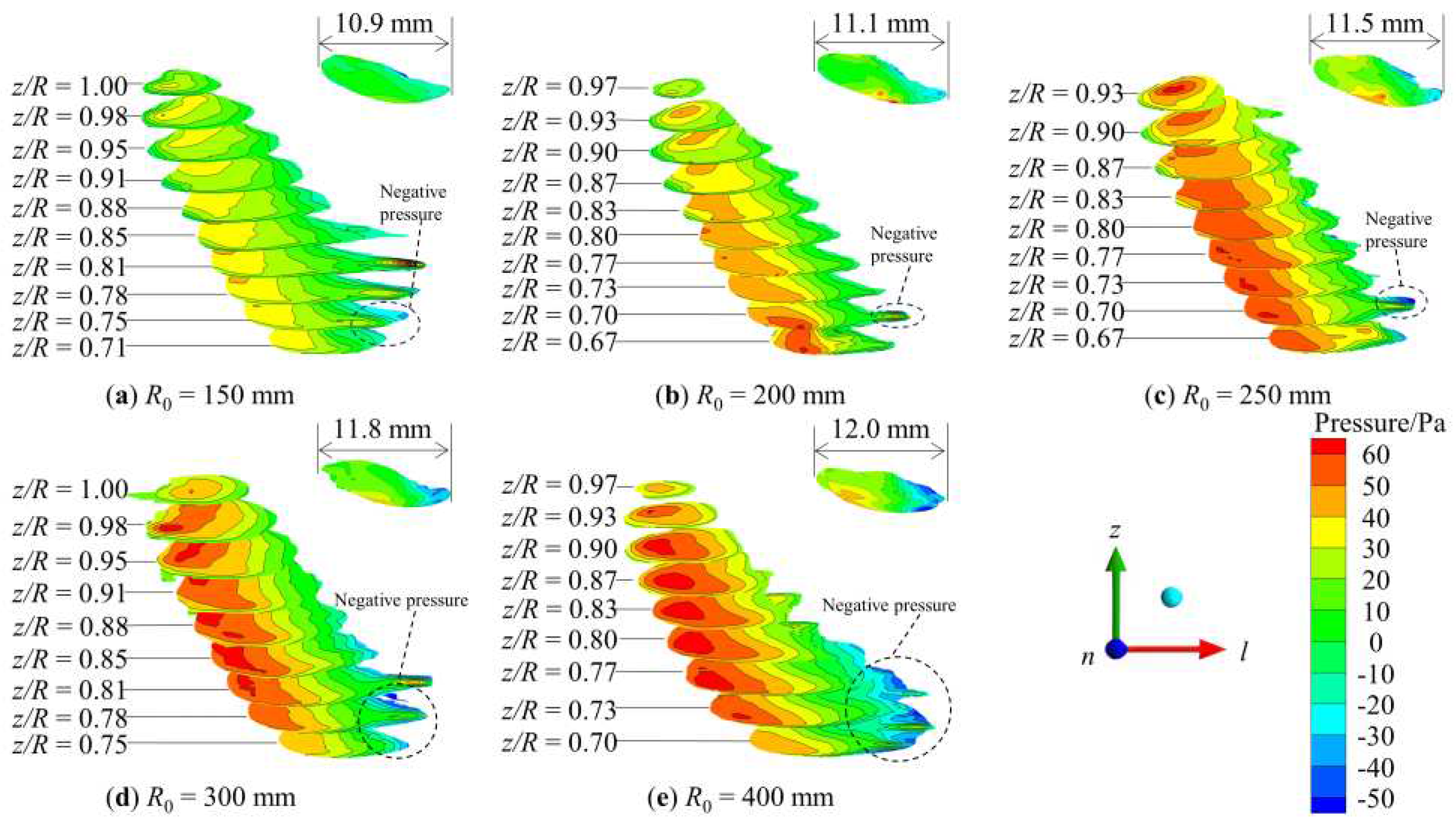
32]. The pressure distribution of multiple sections along the spanwise was applied for studying the droplet internal pressure at
t = 0.20 s, as shown in
Figure 8. The droplet exhibited that a region (left side of the droplet) with positive pressure was outside the jet and a region (right side of the droplet) with negative pressure was in the jet boundary.
Figure 8 shows that the volume of negative pressure region inside the droplet increased significantly with the increase in
R0. The reason is that the jet width narrowed along the wall-normal direction because the centrifugal force was strengthened when the
R0 value was smaller. The streamwise size of the droplet was elongated with an increase of
R0,
Ll of
R0 = 400 mm rises by 10.1% than
Ll of
R0 = 150 mm. Therefore, the droplet was easily broken for the larger
R0 value.
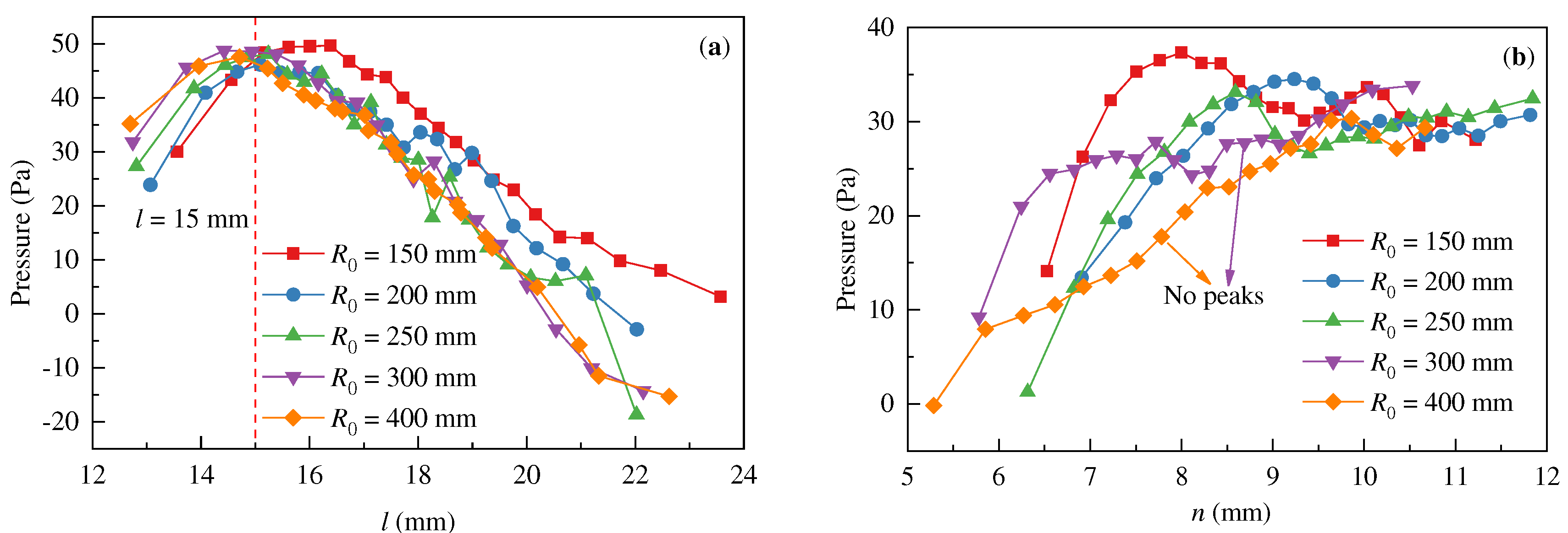
In
Figure 9, the pressure distribution inside the droplet was analyzed along the streamwise and wall-normal direction. As shown in
Figure 9a, the pressure distribution followed a similar trend, with the highest pressure of 50 Pa occurring at
l = 15 mm. The droplet pressure near the jet inlet was lower, and the pressure increased with
R0. A negative pressure region existed inside the droplet away from the jet inlet, but there was no negative pressure inside the droplet for
R0 = 150 mm. As the curvature radius increased, the region and value of negative pressure all increased. This indicates that the pressure difference inside the droplet increased, increasing the droplet length along the streamwise.
Figure 9b reveals that the near-wall pressure of droplet formed significant peaks when
R0 = 150 mm,
R0 = 200 mm, and
R0 = 250 mm. When
R0 = 300 mm, the droplet pressure remained essentially constant, while the pressure of
R0 = 400 mm displayed a linear increase along the wall-normal direction. It was found that the pressure difference near the concave-wall in the droplet decreased as the curvature radius decreased. However, the total pressure difference in the drop was lower for
R0 = 150 mm and
R0 = 200 mm. The droplet distance from the wall increased with the reducing
R0 although the centrifugal force field was enhanced near the concave-wall. For the smaller
R0 value, it was difficult for the droplet to break because the pressure difference inside the droplet was smaller and the distance from the wall increased.
4. Conclusions
The LES-VOF model was employed to perform numerical simulations on the process of single droplet into the concave-wall jet. Three stages of droplet behaviors were obtained, including free-falling outside the jet, spreading at the jet boundary, and ultimately leading to a breakup. In this study, the effect of concave-wall curvature radius on dynamic characteristics of droplet received special attention at the jet boundary.
The investigation revealed that the normalization interfacial energy significant growth during the droplet crossed the jet boundary, and maximum interfacial energy (γmax) ranged from 1.54 to 1.71. Further analysis of the Q-criterion revealed the structure of multi-vortices at the jet boundary, which led to the droplet spreading deformation. The stretched size along the streamwise (Ll) and γmax all increased with R0, therefore, reducing the R0 could effectively decrease droplet spreading deformation and interfacial energy. The study suggested that the intensity and influence range of vortices decreased with the increase of R0, while the droplet breakup was more difficult for the smaller R0 although the centrifugal force was enhanced near the concave-wall. Some results of the droplet were presented that the streamwise size was smaller, the total pressure difference in the drop was lower, and the droplet distance from the wall was larger when R0 was provided as a smaller value. The study provided the theoretical basis for the structural design of the concave-wall jet in liquid-liquid heterogeneous phase separation equipment.
Author Contributions
Methodology, Writing-Original draft preparation, B.G.; Software, Validation, Software Data curation, A.J.; Writing- Reviewing and Editing, J.Z.; Supervision, G.Y.; Visualization, Investigation, Y.L. All authors have read and agreed to the published version of the manuscript.
Funding
This research was funded by the Applied Basic Research Program Project of Liaoning Province of China, grant number 2022JH2/101300077 and the Basic Research Projects of Higher Education Institutions of Education Department of Liaoning Provincial of China, grant number JYTMS20231507.
Data Availability Statement
The data presented in this study are available on request from the corresponding author.
Conflicts of Interest
The authors declare no conflict of interest.
References
- Zhang, M.; Liu, X.; Zhang, C.; Li, X.; Zhang, H.; Tan, Z.; Zhang, L.; Wang, Z. Numerical investigation of shear flow structure induced by guided vane in a liquid-liquid cyclone reactor. Chem. Eng. Process. - Process. Intensif. 2021, 167, 108521. [Google Scholar] [CrossRef]
- Fu, Y.; Wang, H.; Zhang, X.; Bai, L.; Jin, Y.; Cheng, Y. Numerical simulation of liquid mixing inside soft droplets with periodic deformation by a lattice Boltzmann method. J. Taiwan Inst. Chem. Eng. 2019, 98, 37–44. [Google Scholar] [CrossRef]
- Liu, H.; Lu, Y.; Li, S.; Yu, Y.; Sahu, K.C. Deformation and breakup of a compound droplet in three-dimensional oscillatory shear flow. Int. J. Multiph. Flow 2021, 134, 103472. [Google Scholar] [CrossRef]
- Foronda-Trillo, F.; Rodríguez-Rodríguez, J.; Gutiérrez-Montes, C.; Martínez-Bazán, C. Deformation and breakup of bubbles interacting with single vortex rings. Int. J. Multiph. Flow 2021, 142, 103734. [Google Scholar] [CrossRef]
- Xu, Z.; Wang, T.; Che, Z. Droplet breakup in airflow with strong shear effect. J. Fluid Mech. 2022, 941, A54. [Google Scholar] [CrossRef]
- Andersson, R.; Andersson, B. Modeling the breakup of fluid particles in turbulent flows. AIChE J. 2006, 52, 2031–2038. [Google Scholar] [CrossRef]
- Andersson, R.; Helmi, A. Computational fluid dynamics simulation of fluid particle fragmentation in turbulent flows. Appl. Math. Model. 2014, 38, 4186–4196. [Google Scholar] [CrossRef]
- Andersson, R.; Andersson, B. , On the breakup of fluid particles in turbulent flows. AlChE J. 2006, 52, 2020–2030. [Google Scholar] [CrossRef]
- Chen, Y.; Ding, J.; Weng, P.; Yang, X.; Wu, W. On the breakup of Taylor length scale size bubbles and droplets in turbulent dispersions. Chem. Eng. J. 2020, 386, 121826. [Google Scholar] [CrossRef]
- Han, L.; Luo, H.; Liu, Y. A theoretical model for droplet breakup in turbulent dispersions. Chem. Eng. Sci. 2011, 66, 766–776. [Google Scholar] [CrossRef]
- Karthik, G.; Thaker, A.H.; Buwa, V.V. Particle-resolved simulations of catalytic fixed bed reactors: Comparison of turbulence models, LES and PIV measurements. Powder Technol. 2020, 361, 474–489. [Google Scholar] [CrossRef]
- Gomez-Flores, A.; Heyes, G. W.; Ilyas, S.; Kim, H. , Effects of artificial impeller blade wear on bubble-particle interactions using CFD (k-ε and LES), PIV, and 3D printing. Miner. Eng. 2022, 186, 107766. [Google Scholar] [CrossRef]
- Maniscalco, F.; Buffo, A.; Marchisio, D.; Vanni, M. Numerical simulation of bubble columns: LES turbulence model and interphase forces blending approach. Chem. Eng. Res. Des. 2021, 173, 1–14. [Google Scholar] [CrossRef]
- Bao, Y.; Wang, R.; Wang, F.; Tong, S.; Jia, J.; Gao, Z.; Cai, Z. Experimental and numerical investigations of motion and mass transfer of single bubbles in a turbulent flow chamber. J. Taiwan Inst. Chem. Eng. 2022, 136, 104435. [Google Scholar] [CrossRef]
- He, H.; Liu, Z.; Ji, J.; Li, S. Analysis of Interaction and Flow Pattern of Multiple Bubbles in Shear-Thinning Viscoelastic Fluids. Energies 2023, 16, 5345. [Google Scholar] [CrossRef]
- Ying, H.; Puzhen, G.; Chaoqun, W. Experimental and Numerical Investigation of Bubble–Bubble Interactions during the Process of Free Ascension. Energies 2019, 12, 1977. [Google Scholar] [CrossRef]
- Barreiro-Villaverde, D.; Gosset, A.; Mendez, M.A. On the dynamics of jet wiping: Numerical simulations and modal analysis. Phys. Fluids 2021, 33, 062114. [Google Scholar] [CrossRef]
- Chen, Y.; Luo, J.; Wu, F.; Zhang, Z.; Zhao, Z.; Zhang, L.; Luo, C.; Li, X. Multi-objective optimization on flow characteristics of pressure swirl nozzle: A LES-VOF simulation. Int. Commun. Heat Mass Transf. 2022, 133, 105926. [Google Scholar] [CrossRef]
- Liu, Z.; Li, Z.; Liu, J.; Wu, J.; Yu, Y.; Ding, J. Numerical Study on Primary Breakup of Disturbed Liquid Jet Sprays Using a VOF Model and LES Method. Processes 2022, 10, 1148. [Google Scholar] [CrossRef]
- Saeedipour, M.; Schneiderbauer, S. Favre-filtered LES-VOF of two-phase flows with eddy viscosity-based subgrid closure models: An a-posteriori analysis. Int. J. Multiph. Flow 2021, 144, 103780. [Google Scholar] [CrossRef]
- Zhang, J.; Liu, Y.; Gong, B.; Li, X.; Li, Y.; Wu, J. Dynamic Characteristic Analysis of a Single Droplet in a Liquid-Liquid Concave-Wall Jet. Chem. Eng. Technol. 2022, 45, 918–929. [Google Scholar] [CrossRef]
- Zhang, X.; Zhao, W.; Wan, D. A Hybrid Volume-of-Fluid/Euler–Lagrange Method for Vertical Plunging Jet Flows. Int. J. Offshore Polar Eng. 2022, 32, 31–38. [Google Scholar] [CrossRef]
- Ouyang, Y.; Zou, H.-K.; Gao, X.-Y.; Chu, G.-W.; Xiang, Y.; Chen, J.-F. Computational fluid dynamics modeling of viscous liquid flow characteristics and end effect in rotating packed bed. Chem. Eng. Process. - Process. Intensif. 2018, 123, 185–194. [Google Scholar] [CrossRef]
- Vivekanand, S.V.B.; Raju, V.R.K. Effect of wall contact angle and carrier phase velocity on the flow physics of gas–liquid Taylor flows inside microchannels. Chem. Pap. 2018, 73, 1173–1188. [Google Scholar] [CrossRef]
- Daskiran, C.; Xue, X.; Cui, F.; Katz, J.; Boufadel, M.C. Large eddy simulation and experiment of shear breakup in liquid-liquid jet: Formation of ligaments and droplets. Int. J. Heat Fluid Flow 2021, 89, 108810. [Google Scholar] [CrossRef]
- Charin, A.H.; Lage, P.L.; Silva, L.F.L.; Tuković. ; Jasak, H. On the dynamic behavior of rising droplets. Int. J. Multiph. Flow 2019, 110, 165–178. [Google Scholar] [CrossRef]
- Zhang, J.; Zhou, Y.y.; Gong, B.; Li, Y.; Liu, H.L.; Wu, J.H. Flow characteristics of three-dimensional concave-wall jet. CIESC J. 2019, 70, 1340–1348. [Google Scholar]
- Zhang, J.; Li, X.; Gong, B.; Li, Y.; Wang, W.; Wang, S.; Wu, J. Numerical simulation and instability analysis of particles in liquid-solid concave-wall jet using DPM-RSM. Asia-Pacific J. Chem. Eng. 2022, 17, e2765. [Google Scholar] [CrossRef]
- Ubbink, R.I.I. A Method for Capturing Sharp Fluid Interfaces on Arbitrary Meshes on Arbitrary Meshes. J. Comput. Phys. 1999, 153, 26–50. [Google Scholar] [CrossRef]
- Zhang, J.; Gao, Y.; Gong, B.; Li, Y.; Wu, J. Experimental Investigation on Single-Droplet Deformation and Breakup in a Concave-Wall Jet. Chem. Eng. Technol. 2020, 44, 238–247. [Google Scholar] [CrossRef]
- Constantinescu, G.; Miyawaki, S.; Rhoads, B.; Sukhodolov, A.; Kirkil, G. Structure of turbulent flow at a river confluence with momentum and velocity ratios close to 1: Insight provided by an eddy‐resolving numerical simulation. Water Resour. Res. 2011, 47, W05507. [Google Scholar] [CrossRef]
- Liang, X.; Wang, X.; Lu, S.; Wang, K.; Luo, G. Pressure drop analysis for the droplet break-up flow in a locally constrictive microchannel. Chem. Eng. Sci. 2021, 230, 116190. [Google Scholar] [CrossRef]
|
Disclaimer/Publisher’s Note: The statements, opinions and data contained in all publications are solely those of the individual author(s) and contributor(s) and not of MDPI and/or the editor(s). MDPI and/or the editor(s) disclaim responsibility for any injury to people or property resulting from any ideas, methods, instructions or products referred to in the content. |
© 2023 by the authors. Licensee MDPI, Basel, Switzerland. This article is an open access article distributed under the terms and conditions of the Creative Commons Attribution (CC BY) license (http://creativecommons.org/licenses/by/4.0/).
