1. Introduction
Electric power system comprising generation, transmission, distribution, protective devices and loads are dynamic. Therefore, an effective dynamic power conditioning device is required to appropriately synchronise power between these sectors of the power system. Power electronic converter; categorised into rectifiers, inverters, cycloconverters and dc-dc choppers is the most useful and appropriate power conditioning device. Among the family of inverters is the multilevel inverter which provides superior advantages. The popularity and usefulness of multilevel inverters (MLI) is not diminishing anytime soon because MLI continue to attract noteworthy attention in industry and academia. This remarkable attention can be attributed to its’ excellent advantages such as reduced dv/dt stress, reduced switching losses, high quality output waveforms, lower EMI interference, high efficiency, medium and high power applications [
1,
2,
3]. Multilevel inverters are conveniently utilized in power systems such as FACTS and HVDC, electric vehicles, renewable energy generation and grid integration, DVRs (dynamic voltage restorer) and energy storage systems [
4,
5,
6]. Traditional MLI topologies are categorised into three classes namely CHB (Cascaded H-bridge), FC (Flying capacitor) and NPC (Neutral-point clamped) multilevel inverters. These conventional topologies have seen wide-range of improvements. They however suffer from few limitations such as increased switch and dc source count in CHB topology, increased capacitor count in FC topology, increased diode count in NPC topology and structural and control complexities in higher levels for NPC and FC topologies [
7,
8].
The focus of researchers currently is to refine the structure of MLI topologies by placing prominence on higher efficiency, minimising THD and general component quantity mostly power switches, driver circuits and dc sources whiles maximizing the levels of load voltages [
9,
10,
11,
12]. An optimal asymmetrical three-phase multilevel inverter is presented in [
13] which generates 19-level of load voltage per-phase. The device count of the presented topology per phase is 13 switches, 3 dc-sources and 13 driver circuit. The presented topology boast of reduced component quantity and reduced THD. 31-level single phase MLI topology based on cascaded H-bridge structure is presented by [
14] utilizing four asymmetric electrolytic capacitors dc sources, the presented topology amalgamates the merits of chain-cell converter and the concept of static phase-shifter. A modified cascaded 31-level inverter is investigated with respect to reduced dc input, less switches etc. by the authors in [
15], the presented topology is controlled by SIC-PWM to minimize the THD content. A novel topology of single-phase multilevel inverter is presented by the authors in [
16] generates 31-level of load voltage. The topology is derived by modifying the conventional H-bridge structure by incorporating extra switches and dc sources.
A switched capacitor based cascaded single-phase multilevel inverter capable of generating higher levels of load voltage utilizing lower number of components is presented by [
17], the 31-level topology is controlled by nearest level control technique. A high step-up single-phase multilevel composed of unidirectional switches, two dc inputs, power diodes and multiple capacitors is presented in [
18] where the voltage gain is dependent on the quantity of capacitors used and is also easily scalable. Another voltage boosting topology based on switched capacitor network and cross-switched configurations is presented by the authors in [
19]. The dc source count is one but the switches and diodes count are high. A novel hybrid clamped 7-level inverter composed of reduced component quantity and competitive performance is presented in [
20], this topology is an improvement of the traditional diode-clamped and provides floating capacitor voltage balancing at switching frequencies thus provide low voltage ripples. This work propounds a new cascaded three-phase multilevel inverter founded on a cascaded submultilevel and single-phase H-bridge structures comprising minimum component quantities such as dc sources, power switches and driver circuits. Contrastive analysis of the proffered inverter and some selected publicized topologies shows the proffered topology exhibits superior advantages. The remainder of this research is subdivided into the ensuing parts: section II encapsulates the proffered topology made-up of basic and cascaded submultilevel units. Contrastive analysis of the proffered topology and existing topologies is set forth in section III. Simulation of the proffered topology is presented in section IV and conclusion is presented in section V.
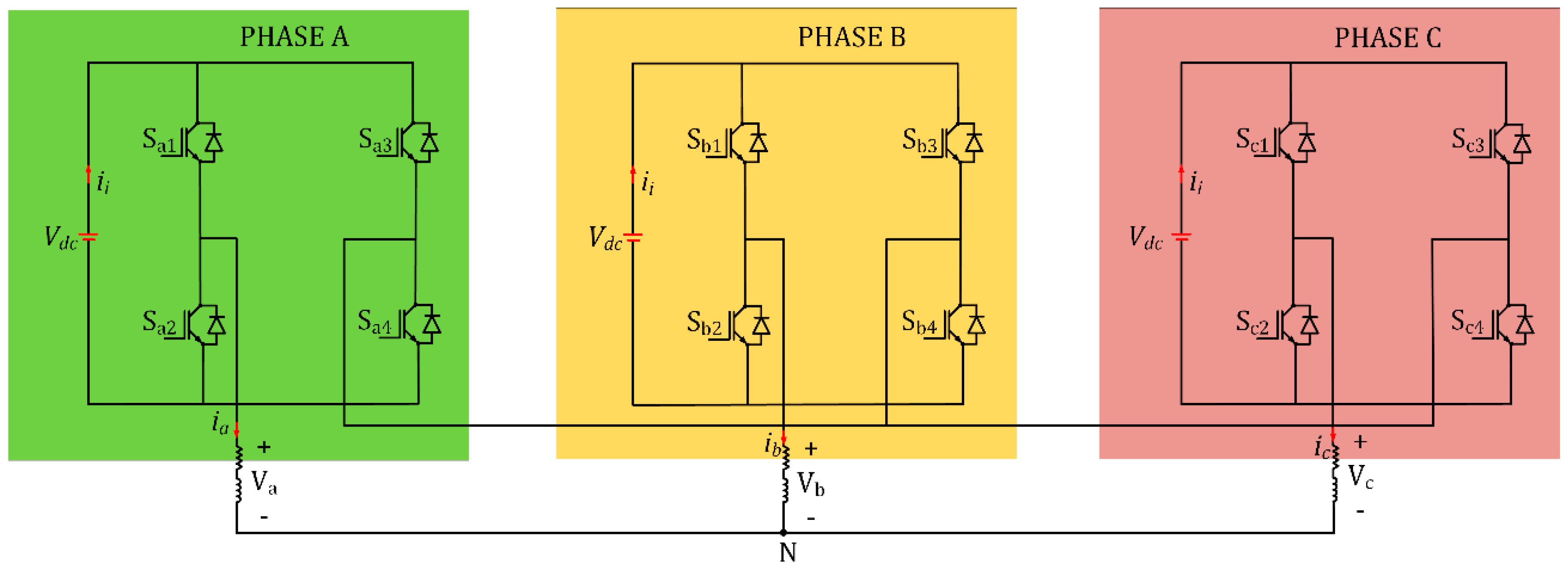
Figure 1.
Three-phase multilevel inverter grounded on three single-phase H-bridge inverters.
Figure 1.
Three-phase multilevel inverter grounded on three single-phase H-bridge inverters.
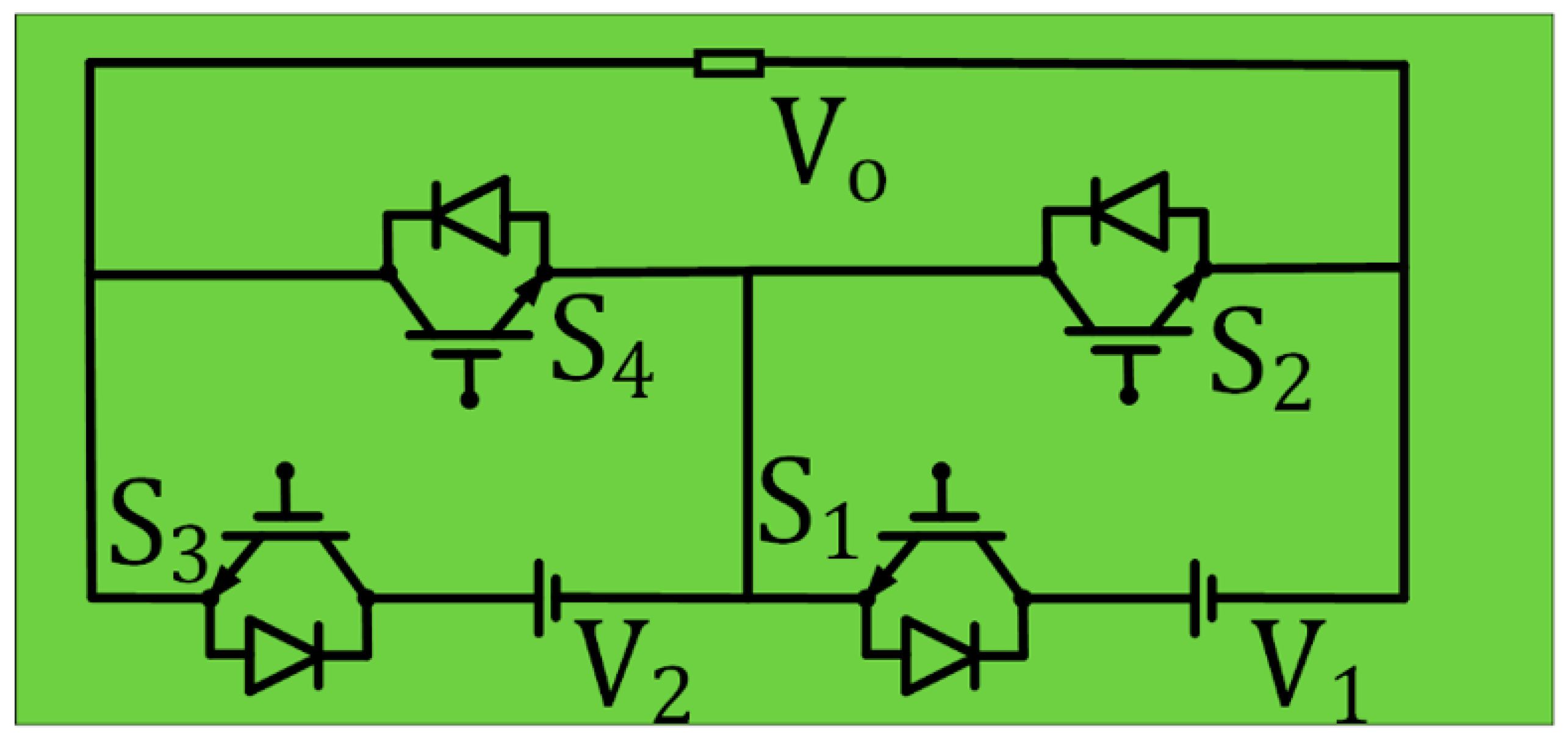
Figure 3.
Submultilevel unit.
Figure 3.
Submultilevel unit.
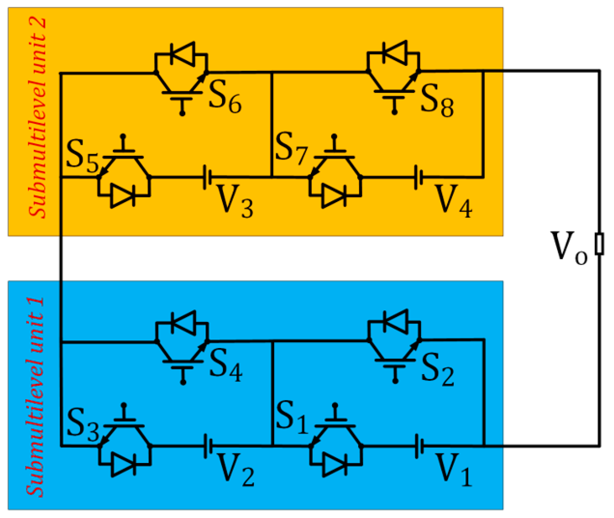
Figure 4.
Cascaded submultilevel structure.
Figure 4.
Cascaded submultilevel structure.
Figure 5.
Deriving the proposed cascaded three-phase topology.
Figure 5.
Deriving the proposed cascaded three-phase topology.
2. Materials and Methods
2.1. Proposed Topology
Figure 1 shows the power circuit of a three-phase multilevel inverter based on three conventional single-phase H-bridge inverters. The proposed three-phase multilevel inverter is derived by modifying the power circuit of the conventional three-phase multilevel inverter of
Figure 1. The input/source voltage section of each phase of
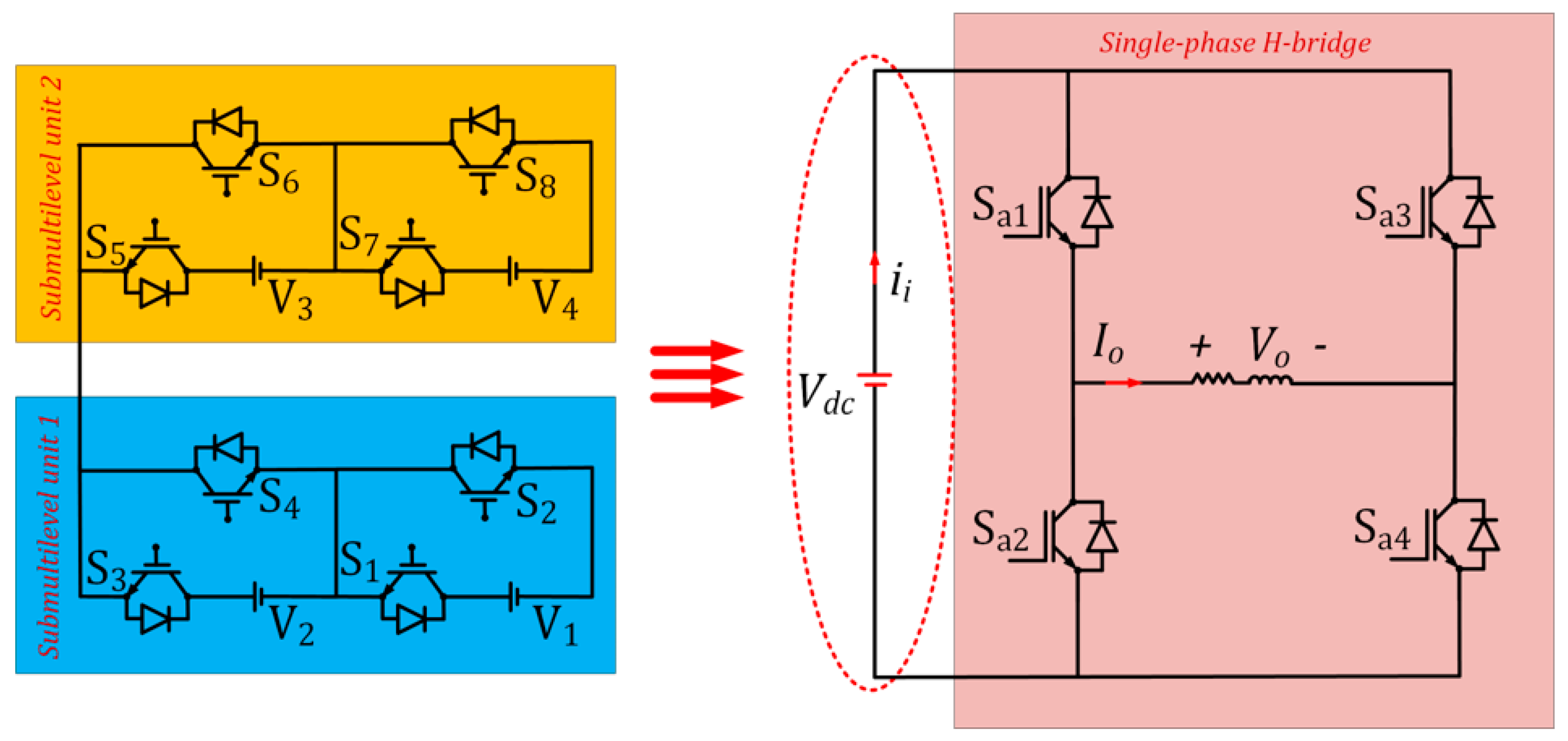
Figure 1 is replaced with a cascaded submultilevel structure shown by
Figure 4. The submultilevel structure shown by
Figure 3 is derived by cascading two basic units.
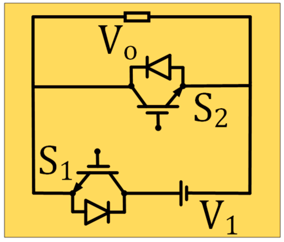
Figure 2. shows the basic unit of the proffered three-phase multilevel inverter built by two switches and one dc source. Therefore, the submultilevel structure entails four unidirectional switches and two dc sources. Only positive output voltages are generated by the basic unit (
Figure 2) and the submultilevel (
Figure 3), consequently, an H-bridge structure is needed to produce both polarities load voltage.
Figure 5 shows the derivation of the proffered cascaded three-phase multilevel inverter by replacing the voltage source of each phase of
Figure 1 with a cascaded submultilevel structure. The proffered three-phase multilevel inverter is a cascaded structure based on the submultilevel units.
Figure 6 shows the proffered three-phase multilevel inverter based on the cascaded submultilevel structure. The cascaded structure for each phase of the proffered three-phase multilevel inverter of
Figure 6 is composed of eight voltage unidirectional power switches and four dc sources. The cascaded three-phase structure is composed of twenty-four voltage unidirectional switches and twelve dc sources. The overall component count of the proposed three-phase multilevel inverter will have to include the H-bridge structure in each phase, each H-bridge structure contains four unidirectional switches. Therefore, the proposed cascaded three-phase multilevel inverter of
Figure 6 comprises thirty-six voltage unidirectional switches and twelve dc sources. Component distribution of the proffered multilevel inverter are computed by equation (1) where
NDC-Sources,
NDriver, Nswitches, NLevel, and
NIGBT denotes dc source, driver circuit, switch, output voltage level, and IGBT count accordingly. The switch, IGBT and driver circuit count are equal because no bidirectional switches are used. Also,
denotes the number of basic unit in the cascaded structure.
2.2. Input Voltage Characteristics
Based on the value of input dc sources, multilevel inverters are grouped into symmetric or asymmetric topologies. In symmetric topologies, the magnitude of all input dc sources are equivalent. If the magnitude of input dc sources varies, the topology is classified as asymmetric; which is further categorised into binary and trinary topologies. Asymmetric topologies generate much more levels of output voltage juxtaposed to symmetric topologies. However, the rate of depletion of the input sources in asymmetric topologies is variable. Based on symmetric and asymmetric characteristics of the input dc sources, 5 algorithms of voltage permutations are presented in
Table 1 to select the optimal source voltage. In
Table 1, the second column indicates the type of input voltage, the third column indicates the level of generated output voltage
, the fourth column indicates the maximum voltage
.
denotes the number of basic unit in the cascaded structure. The first algorithm is symmetric while the remaining algorithms (2nd to 5th) are a variety of asymmetric.
Using the first algorithm as the input voltage,
Figure 2 and
Figure 3 generates 1-level and 2-level of positive output voltages respectively.
Figure 4 and
Figure 6 generates 5-level (
) and 9-level (
) of output voltages respectively. Using the fifth algorithm,
Figure 2 and
Figure 3 generates 1-level (
) and 3-level (
) of positive output voltages respectively.
Figure 4 and
Figure 6 generates 16-level (
) and 31-level (
) of output voltages respectively. Therefore, from the 5 proposed algorithms of
Table 1, the fifth algorithm yields the maximum output voltage (
) and the maximum output levels (
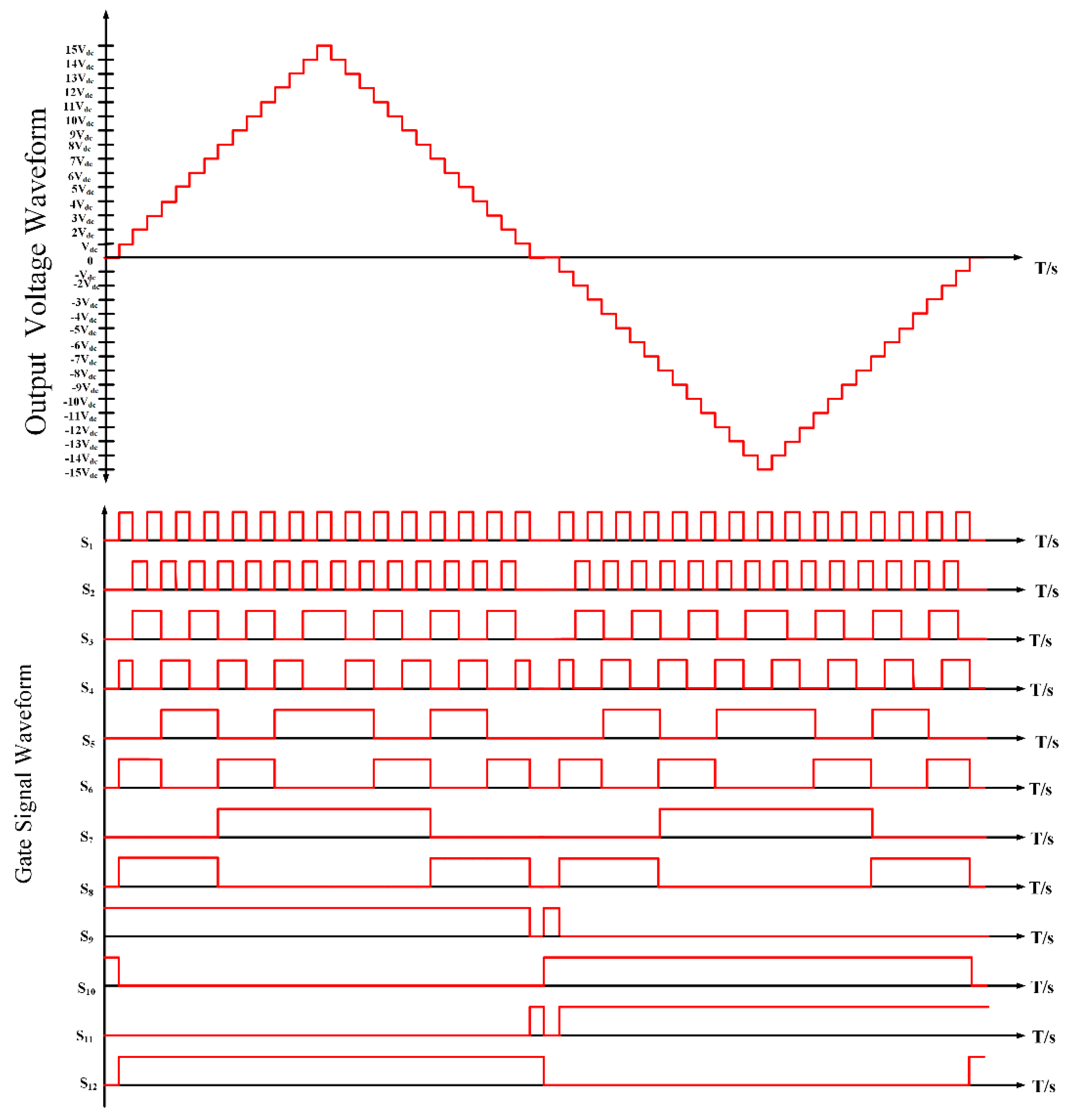
). The theoretical output waveform of the proposed 31-level inverter (
Figure 6) and the corresponding switching states of the power switches is illustrated by
Figure 7. The switching pattern of the proposed 31-level inverter is given in
Table 2, only active switches in one phase per state is provided, the corresponding switches in the other phases are active for the same state. All other switches are in the off-state or voltage blocking state.
2.3. Inverter Power Loss
Power loss of the proposed topology is determined by two parameters: switching power loss and conduction power loss. Switching losses occur during switching states of the inverter whiles conduction losses occur during active states of switches. Blocking voltage power losses are present but are ignored because IGBT off-state leakage currents are negligible.
2.3.1. Switching losses
Switching losses of the proposed multilevel inverter occurs during the gating action of on/off of the power switches. These losses are computed as energy losses during on/off gating. Hence
Eon and
Eoff constitute the on/off gating states accordingly. Overall switching energy losses P
SW is computed by equation (4) where
Vsw is the off-mode switch voltage,
I and
I’ are the on/off switch currents accordingly.
ton and
toff are the time in seconds for turn-on and turn-off accordingly.
2.3.2. Conduction losses
Conduction losses of the proposed multilevel inverter occurs when the power switches are conducting. Each power comprises one transistor fitted with an antiparallel diode. Therefore, conduction power losses
PC is computed by summing the transistor
PC,T and diode
PC,D power losses. The magnitude of
β is constant and depends on the kind of power switch used. The diode and transistor resistance are denoted by
RD and
RT accordingly, also
VT denotes the transistor voltage whiles and
VD denotes the diode voltage accordingly. Integrating equation (5) for a period will yield transistor average conduction power loss equation expressed by equation (7), also integrating equation (6) for a period will yield diode average conduction power loss equation expressed by equation (8). The conduction cycle alternates when the control methods and load characteristics are taken into account. Therefore, the overall inverter power loss
PL is computed by equation (9) and the converter efficiency is computed by equation (10).
Therefore, inverter efficiency (
) is computed by:
2.4. Standing/Blocking Voltage
Overall standing voltage of the proffered inverter is determined by computing and summing the blocking voltage of each switch during the off-state or mode. Because of the symmetric relationship between the phases, it enough to determine the standing voltage of one phase then multiple by three to achieve the overall standing voltage of the inverter. There are twelve unidirectional switches per-phase. Eight switches are in the cascaded topology; switches in individual basic units are equivalent with respect to the blocking voltage, this is expressed by equation (11). Four are in the H-bridge and are all equivalent with respect to the blocking voltage, this is expressed by equation (12). Therefore, the total standing voltage is computed by equation (13).
3. Results
3.1. Comparative Analysis
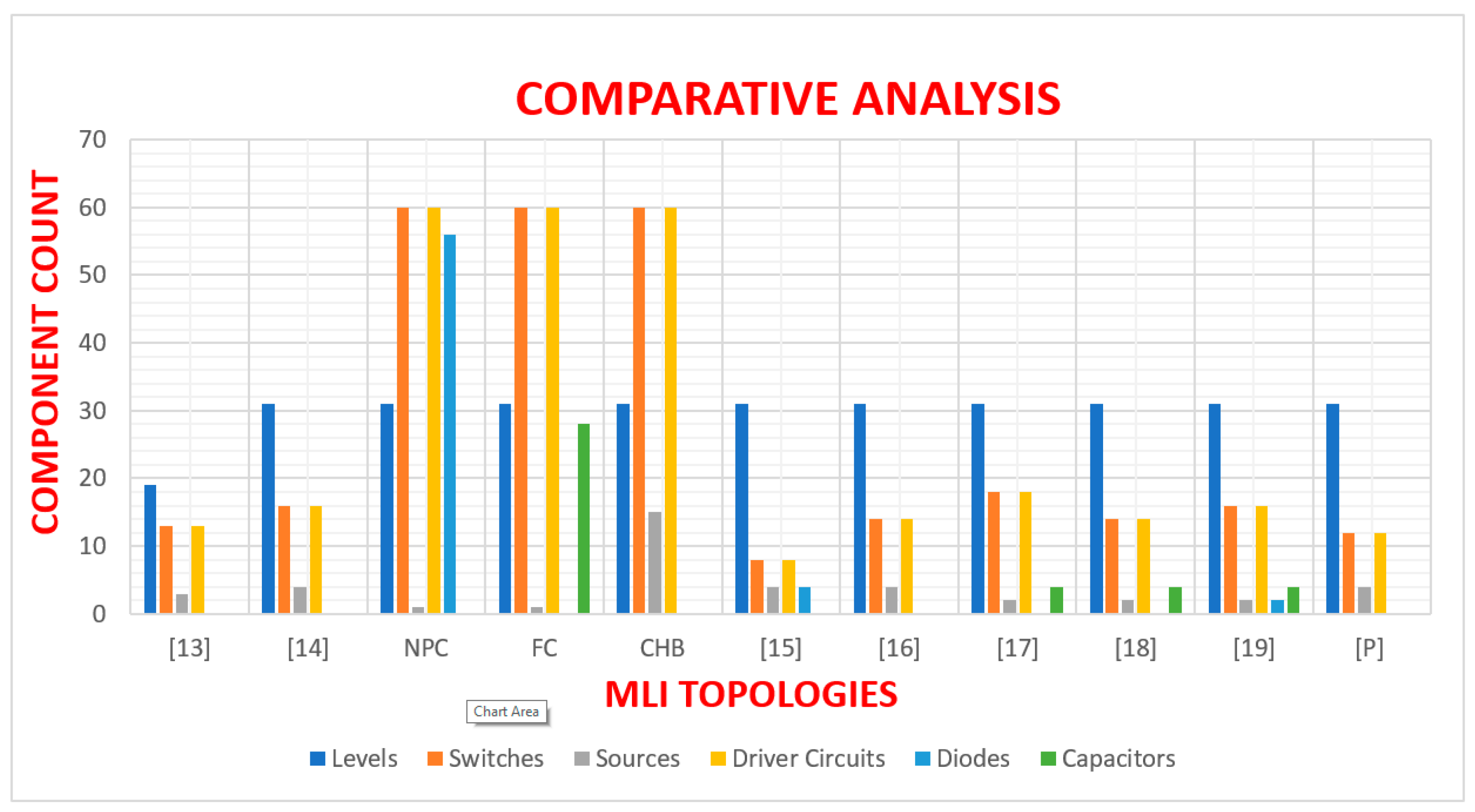
Comparative investigation of the proposed cascaded multilevel topology and selected published multilevel inverters are analysed in this section with respect to component quantity and output voltage levels. Multilevel inverters with higher number of components i.e., switches, driver circuits, dc sources etc. have increased volume and weight, increased cost, high losses and reduced efficiency. Therefore, it’s imperative to design a topology having reduced component count and higher output voltage levels. Based on
Table 3, a phase of the proposed topology is juxtaposed with selected single-phase multilevel inverter topologies. Each phase of the proposed topology comprises 12 switches, 4 dc sources and 12 driver circuit. Evidently, it’s clear the proposed topology contains less components juxtaposed with the selected topologies. There are no fictitious dc sources such as capacitors as existing in [
17,
18,
19], all switches in the proposed topology are unidirectional thus less complex compared to bidirectional switches which are complex structurally, also there are no clamping diodes and capacitors as in NPC and FC topologies.
Figure 8 shows a bar chart representation of the comparative analysis of
Table 3.
Table 4 shows comparative evaluation of the proffered topology and selected three-phase multilevel inverter topologies with respect to the quantity of switches, sources, driver circuit, clamping diodes and capacitors, output voltage levels and source capacitors. It evident that the proposed topology provides the optimal cost benefit analysis when component quantity is juxtaposed with the levels of output voltage.
3.2. Simulation Results
Simulation results of the proffered cascaded three-phase multilevel inverter of
Figure 6 is provided in this section. Using fundamental frequency control technique and an appropriate switching sequence, the required output waveforms are generated by developing and simulating the power circuit of the proffered multilevel inverter in PSCAD/EMTDC software. High switching frequencies provide high quality output waveforms, however, switching losses are increased. Compared to PWM control techniques, fundamental frequency control provides minimum switching losses [
27,
28].
Table 5 shows the variables used for simulation.
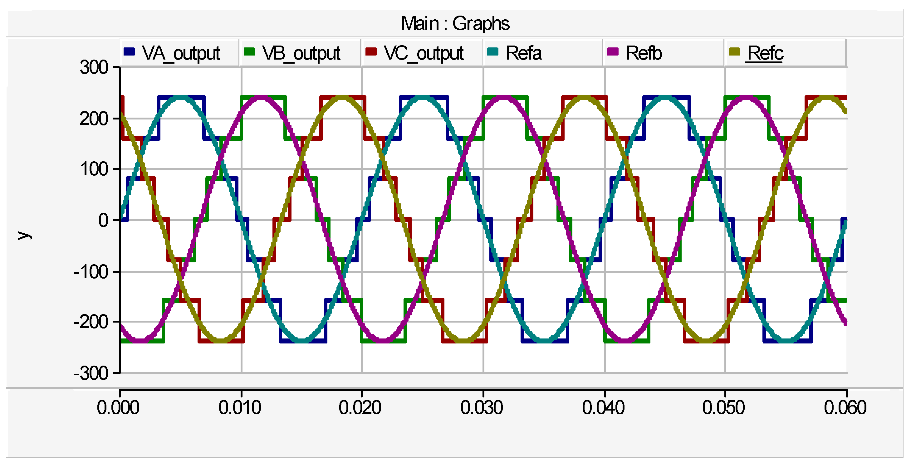
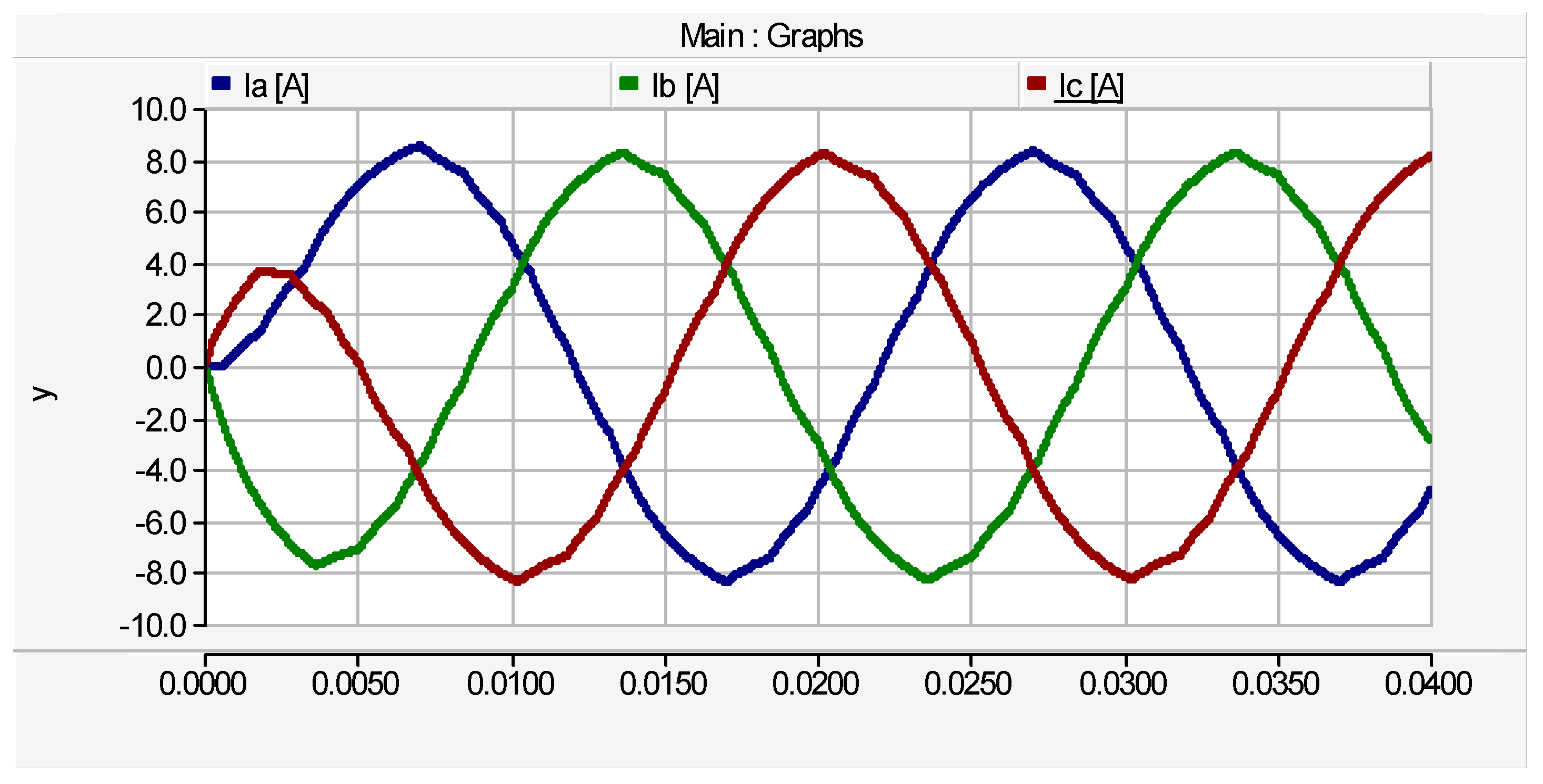
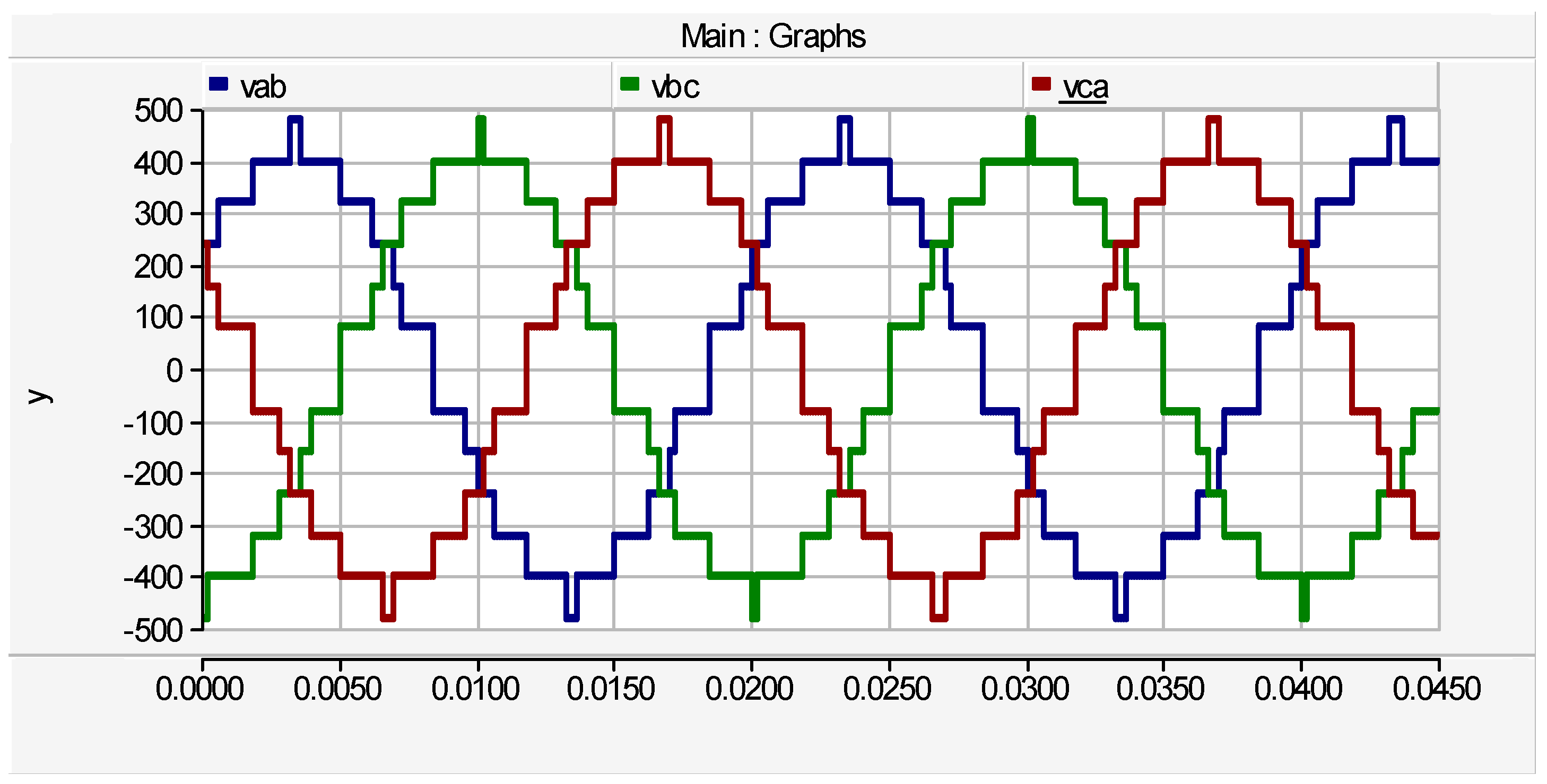
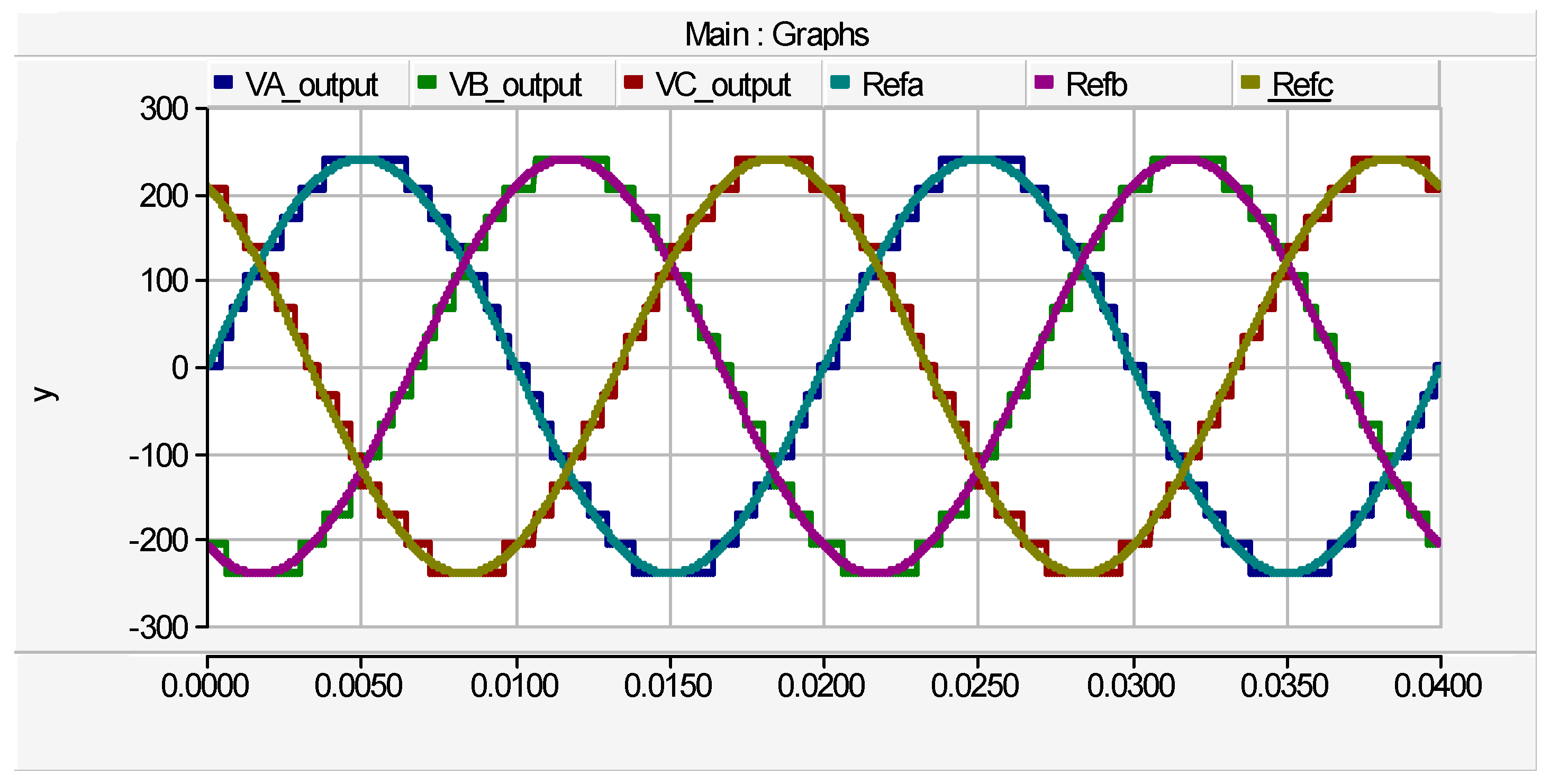
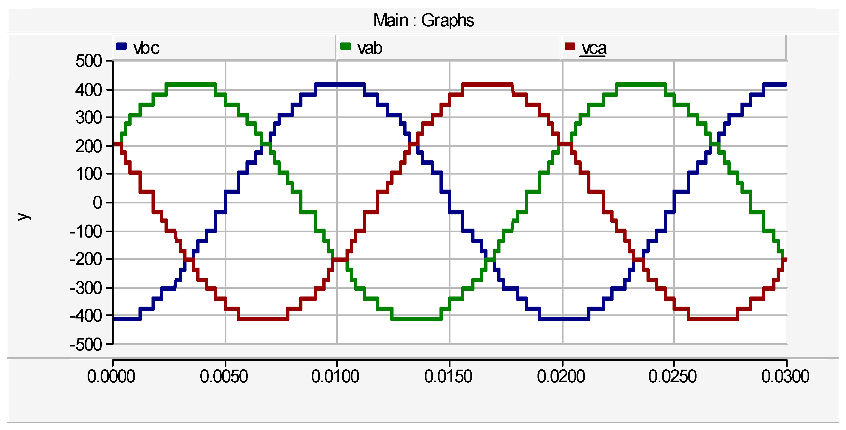
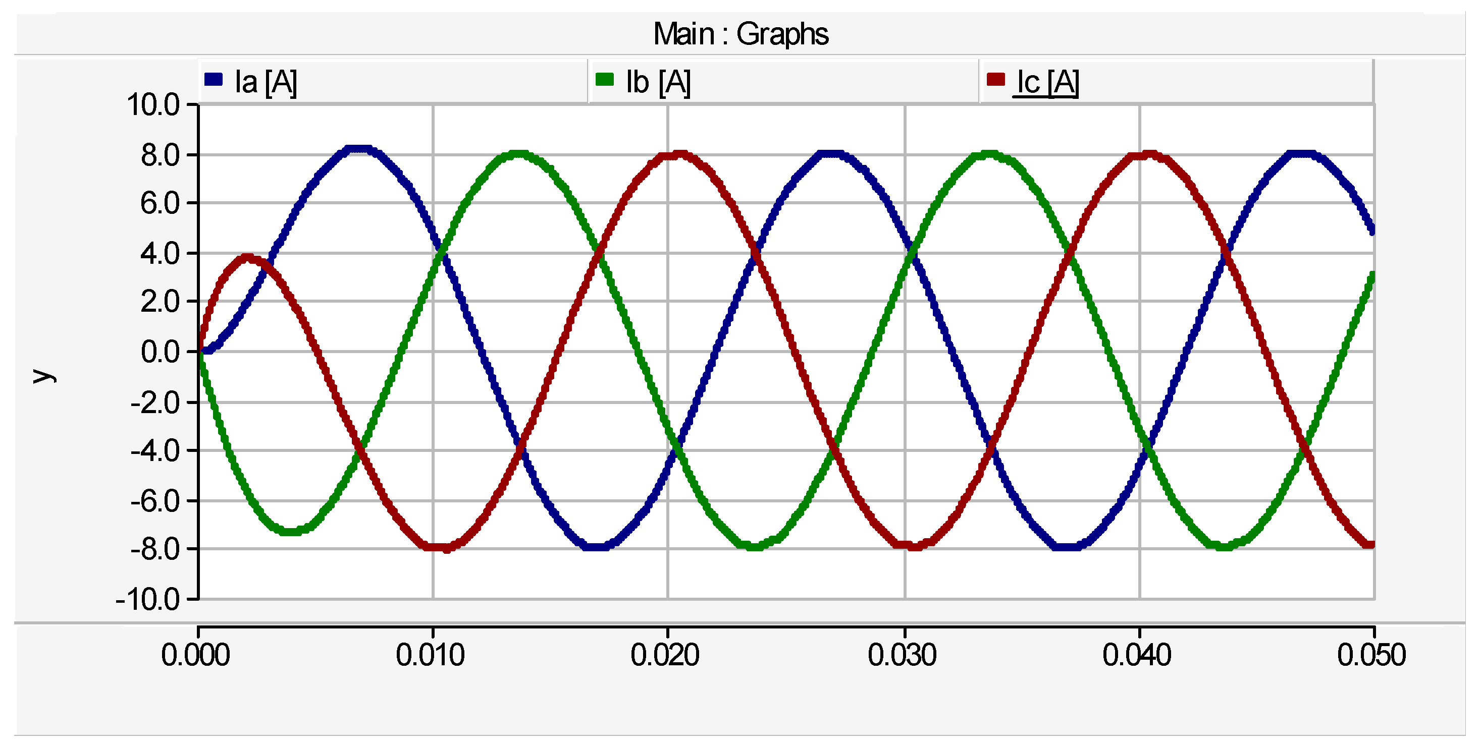
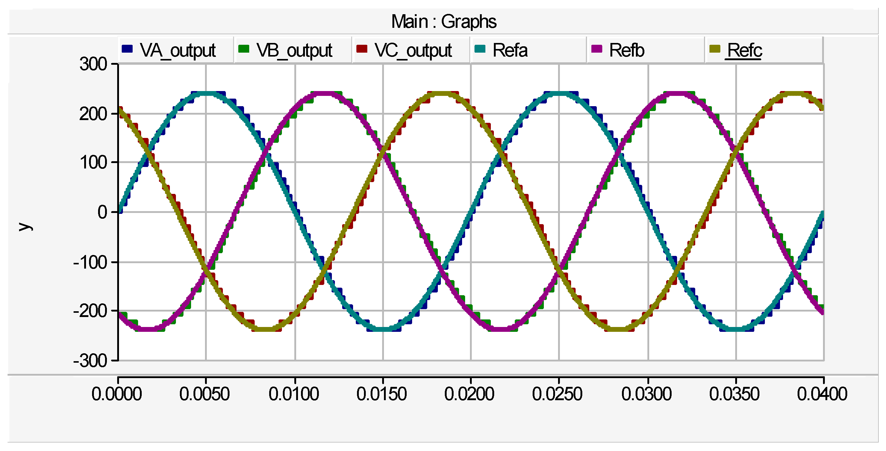
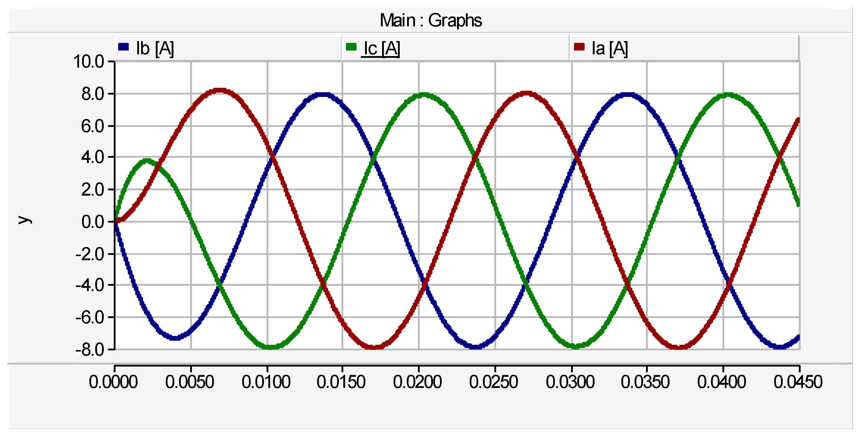
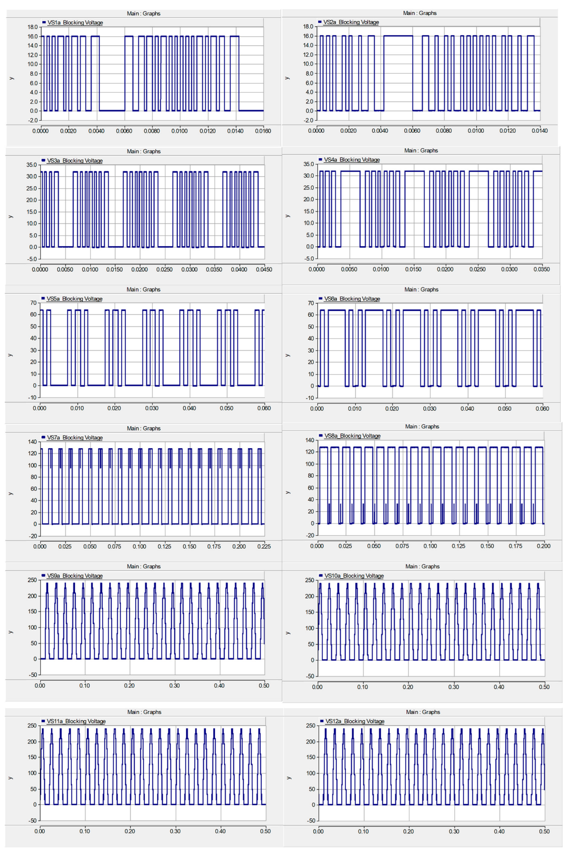
Simulation results of the proposed three-phase cascaded multilevel inverter are illustrated by the waveforms of by
Figure 9 to Figure 18. Three cases of the cascaded topology are investigated for the proposed multilevel inverter. The first case consists of one submultilevel unit (or two cascaded basic unit), the second case consist of a cascaded topology of three basic units (i.e., one submultilevel and one basic unit). Finally, the third case consist of a cascaded topology of two submultilevel units (i.e., four basic units). The phase voltage waveforms are composed of the step output voltages (V
A, V
B and V
C) and corresponding reference voltages (Refa, Refb and Refc) which perfectly align together. The generated output waveforms of the first case are illustrated by
Figure 9 to
Figure 11. The phase voltage waveforms with peak value of
are depicted by
Figure 9. The phase current waveforms with peak value of ±8.1
A are depicted by
Figure 10. The line voltage waveforms are shown by
Figure 11 having peak value of ±415
V. The first case has two dc sources with maximum output voltage of 240
V. Therefore, the magnitude of input voltage is expressed by equation (14):
The output waveforms of the second case are illustrated by
Figure 12 to
Figure 14. The phase voltage waveforms with peak value of
are depicted by
Figure 12. The line voltage waveforms are shown by
Figure 13 having peak value of
. The phase current waveforms with peak value of
are depicted by
Figure 14. The second case has three dc sources with maximum output voltage of
. Therefore, the magnitude of input voltage is expressed by equation (15):
The output waveforms of the third case are illustrated by
Figure 15 to
Figure 18. The phase voltage waveforms with peak value of
are depicted by
Figure 15. The line voltage waveforms are shown by
Figure 17 having peak value of
. The phase current waveforms with peak value of
are depicted by
Figure 16. The blocking voltage waveforms are illustrated by
Figure 18, where switches in individual basic unit have equal blocking voltage and switches in the H-bridge have equal blocking voltage. The third case has four dc sources with maximum output voltage of
. Therefore, the magnitude of input voltage is expressed by equation (16):
5. Conclusions
This work proffered a new cascaded three-phase multilevel inverter gounded on a cascaded submultilevel and single-phase H-bridge structures. The per-phase component distribution of the proposed topology are twelve unidirectional power switches, four dc sources and twelve driver circuits. Five algorithms of source voltage are proposed and the optimal algorithm selected to generate the peak load voltage and output levels. The proposed MLI is switched with high switching frequencies which provide high quality output waveforms, however, switching losses are increased. Contrastive evaluation of the proposed inverter and existing topologies shows the superb merits of the proffered MLI. Functionality of the proffered MLI is substantiated by simulation where three cases of the cascaded topology are investigated for the proposed multilevel inverter. The results of the simulated topologies where the first case is a submultilevel unit (or two cascaded basic units), the second case is three basic units (i.e., one submultilevel and one basic unit) and the third case is two submultilevel units (i.e., four basic units) shows that the phase voltage waveforms composed of step load voltages (VA, VB and VC) and corresponding reference voltages (Refa, Refb and Refc) perfectly align together.
Author Contributions
Conceptualization, S.N.T., O.C.O. and S.T.M.; methodology, S.N.T and A.S.A.H, software, S.N.T. and S.T.M.; validation, O.C.O. and A.S.A.H, formal analysis, S.N.T.; investigation, X.X.; resources, S.N.T., O.C.O., S.T.M. and A.S.A.H; writing—original draft preparation, S.N.T. and O.C.O.; writing—review and editing, S.T.M. and A.S.A.H. All authors have read and agreed to the published version of the manuscript
Conflicts of Interest
The authors declare no conflict of interest.
References
- S. N. Tackie and E. Babaei, “Modified Topology for Three-Phase Multilevel Inverters Based on a Developed H-Bridge Inverter,” Electronics, vol. 9, no. 11, pp. 1848, Nov. 2020. [CrossRef]
- H. Aghaei, E. Babaei and M. B. B. Sharifian, “Two Compact Three-Phase Multilevel Inverters for Low-Voltage Applications,” in IEEE Transactions on Power Electronics, vol. 38, no. 1, pp. 647-656, Jan. 2023. [CrossRef]
- T. Debnath, R. Resalayyan, M. Imthias, K. Gopakumar, L. Umanand and W. Jarzyna, “A Multilevel Inverter for Instantaneous Voltage Balancing of Single Sourced Stacked DC-Link Capacitors for an Induction Motor Load,” in IEEE Transactions on Power Electronics, vol. 37, no. 9, pp. 10633-10641, Sept. 2022. [CrossRef]
- H. Mondol, S. Prokash Biswas, R. Islam, A. M. Mahfuz-Ur-Rahman and K. M. Muttaqi, “A New Hybrid Multilevel Inverter Topology with Level Shifted Multi-carrier PWM Technique for Harvesting Renewable Energy,” 2020 IEEE Industry Applications Society Annual Meeting, Detroit, MI, USA, 2020, pp. 1-6.
- S.N. Tackie B.K. Kurehwatira, “Switched Inductor Capacitor Based DC-AC Converter for PV Applications,” International Journal on “Technical and Physical Problems of Engineering (IJTPE), vol. 14, no. 1, pp. 238-246, March 2022.
- C. Buccella, C. Cecati, M. G. Cimoroni and K. Razi, “Analytical Method for Pattern Generation in Five-Level Cascaded H-Bridge Inverter Using Selective Harmonic Elimination,” in IEEE Transactions on Industrial Electronics, vol. 61, no. 11, pp. 5811-5819, Nov. 2014. [CrossRef]
- E. Babaei, “A cascade multilevel converter topology with reduced number of switches,” IEEE Trans. Power Electron., vol. 23, no. 6, pp. 2657–2664, Nov. 2008. [CrossRef]
- Masaoud, H. W. Ping, S. Mekhilef, and A. S. Taallah, “New three-phase multilevel inverter with reduced number of power electronic components,” IEEE Trans. Power Electron., vol. 29, no. 11, pp. 6018–6029, Nov. 2014. [CrossRef]
- E. Babaei, M. F. Kangarlu, F. N. Mazgar, “Symmetric and asymmetric multilevel inverter topologies with reduced switching devices,” Electric Power Systems Research, vol. 86, pp. 122-130, 2012. [CrossRef]
- E. Babaei, M. F. Kangarlu, M. Sabahi, “Extended multilevel converters: an attempt to reduce the number of independent DC voltage sources in cascaded multilevel converters,” IET Power Electronics, vol. 7, no. 1, pp. 157-166, 2014. [CrossRef]
- K. Thakre, C. B. Mohanty, A. Chatterjee, V. S. Kommukuri, “A modified circuit for symmetric and asymmetric multilevel inverter with reduced components count,” International Transactions on Electrical Energy Systems. 2019;e12011. [CrossRef]
- Dash AR, Panda AK, Patel R, Penthia T. Design and implementation of a cascaded transformer coupled multilevel inverter-based shunt active filter under different grid voltage conditions. International Transactions on Electrical Energy Systems. 2019;29(2):e2728. [CrossRef]
- C. Dhanamjayulu, P. Kaliannan, S. Padmanaban, P. K. Maroti and J. B. Holm-Nielsen, “A New Three-Phase Multi-Level Asymmetrical Inverter with Optimum Hardware Components,” in IEEE Access, vol. 8, pp. 212515-212528, 2020. [CrossRef]
- C. K. Lee, S. Y. Ron Hui and Henry Shu-Hung Chung, “A 31-level cascade inverter for power applications,” in IEEE Transactions on Industrial Electronics, vol. 49, no. 3, pp. 613-617, June 2002. [CrossRef]
- K. Muralikumar and P. Ponnambalam, “Comparison of Fuzzy and ANFIS Controllers for Asymmetrical 31-Level Cascaded Inverter with Super Imposed Carrier PWM Technique,” in IEEE Access, vol. 9, pp. 82630-82646, 2021. [CrossRef]
- D. Prasad, C. Dhanamjayulu, S. Padmanaban, J. B. Holm-Nielsen, F. Blaabjerg and S. R. Khasim, “Design and Implementation of 31-Level Asymmetrical Inverter with Reduced Components,” in IEEE Access, vol. 9, pp. 22788-22803, 2021. [CrossRef]
- Ahmad, M. Anas, A. Sarwar, M. Zaid, M. Tariq, J. Ahmad, and A. R. Beig, “Realization of a Generalized Switched-Capacitor Multilevel Inverter Topology with Less Switch Requirement,” Energies, vol. 13, no. 7, p. 1556, Mar. 2020. [CrossRef]
- R. S. Alishah, S. H. Hosseini, E. Babaei, M. Sabahi, A. Zare, “A New Extended High Step-Up Structure for Multilevel Converter”. IET Power Electron. vol. 9, pp. 1894–1902, 2016.
- T. Roy, P. K. Sadhu, and A. Dasgupta, ‘‘Cross-switched multilevel inverter using novel switched capacitor converters,’’ IEEE Trans. Ind. Electron., vol. 66, no. 11, pp. 8521–8532, Nov. 2019. [CrossRef]
- H. Tian, Y. Li and Y. W. Li, “A Novel Seven-Level Hybrid-Clamped (HC) Topology for Medium-Voltage Motor Drives,” in IEEE Transactions on Power Electronics, vol. 33, no. 7, pp. 5543-5547, July 2018.
- K. Yadav, K. Gopakumar, K. R. R, L. Umanand, S. Bhattacharya and W. Jarzyna, “A Hybrid 7-Level Inverter Using Low-Voltage Devices and Operation with Single DC-Link,” in IEEE Transactions on Power Electronics, vol. 34, no. 10, pp. 9844-9853, Oct. 2019. [CrossRef]
- G. Waltrich and I. Barbi, “Three-phase cascaded multilevel inverter using power cells with two inverter legs in series,” IEEE Trans. Ind. Electron., vol. 57, no. 8, pp. 2605–2612, Aug. 2010.
- M. M. Hasan, A. Abu-Siada, and M. S. A. Dahidah, “A Three-Phase Symmetrical DC-Link Multilevel Inverter with Reduced Number of DC Sources”, IEEE Transactions on Power Electronics, vol. 33, no. 10, October 2018. [CrossRef]
- S. Sabyasachi, V. B. Borghate, R. R. Karasani, S. K. Maddugari, and H. M. Suryawanshi, “Hybrid Control Technique-Based Three-Phase Cascaded Multilevel Inverter Topology” in IEEE Access, vol. 5, pp. 26912- 26921, 2017.
- M. Hassanifar, M. Farhadi-Kangarlu and R. Choupan, “A Novel Three-phase Multilevel Inverter with Reduced Number of IGBTs, Developed for Drive Application,” 11th Power Electronics, Drive Systems, and Technologies Conference (PEDSTC), Tehran, Iran, 2020, pp. 1-5.
- T. A. Ahmed, E. E. M. Mohamed, A.R. Youssef, A. A. Ibrahim, M. S. R. Saeed, A. I. M. Ali, “Three phase modular multilevel inverter-based multi-terminal asymmetrical DC inputs for renewable energy applications,” Engineering Science and Technology, an International Journal, vol. 23, no. 4, pp. 831-839, 2020. [CrossRef]
- S. N. Tackie, N. M. Komi, O. C. Ozerdem, “31-Level Single-Phase Cascaded Inverter with Minimal Component Count”, International Journal on “Technical and Physical Problems of Engineering (IJTPE), vol. 15, no. 1, pp. 271-282, March 2023.
- P. Gaur, P. Singh, “Various control strategies for medium voltage high power multilevel converters: A review”, In Proceedings of the 2014 Recent Advances in Engineering and Computational Sciences (RAECS), Chandigarh, India, pp. 1–6, 6–8 March 2014.
|
Disclaimer/Publisher’s Note: The statements, opinions and data contained in all publications are solely those of the individual author(s) and contributor(s) and not of MDPI and/or the editor(s). MDPI and/or the editor(s) disclaim responsibility for any injury to people or property resulting from any ideas, methods, instructions or products referred to in the content. |
© 2023 by the authors. Licensee MDPI, Basel, Switzerland. This article is an open access article distributed under the terms and conditions of the Creative Commons Attribution (CC BY) license (https://creativecommons.org/licenses/by/4.0/).
