1.1. Introduction:
Vision is the basic need of all human beings. With sight every person can enjoy their life. Loss of vision makes people depends on other. Because of lack of vision thousands of human beings are away from their goals. According to new observation “about 288 million peoples are visually impaired in the present world”. 91% of these visually impaired people who depends on others to meet their needs of life. Visually impaired person are not able to take any benefit of different kinds of service. They face huge difficulties for survival in unknown environment. Visual impaired people are limited in their mobility. It is difficult for visually impaired person to move from one place to another place singly because they cannot find out their position and object placement in an unknown environment.
Primary mobility devices work like tool for sightless persons are the white cane and guide dog the white cane represents a simple cane which detect static obstacle via tectile force feedback The white cane is a wide instrument composed of stick which are white in colour having red head. Information from environment enables the human knowing about origin and sound exist in the surrounding likes noises of machinery transport signal etc. sightless people take a lot of advantages from the signals to protect its security.
The second method is guiding a dog there are special type of trained dog. These guiding dogs alert the blind person about the objects coming in their path. And persuade the individual to reverse his way direction. These guiding dogs has a lot of restriction because of the challenging guidance supplied by the doges. These guiding dogs are very expensive to afforded for poor people of society.
After 2nd world war many sensor devices were made which help the visually impaired people for their survival activities in the surrounding. The use of sensor technology for impaired people is the greatest achievement. The purposes of our project is to design such a system which cooperate sightless persons life actions without the exploit of these expensive white cane and guide dog.
In our project we will make the use of infrasonic system which use the low frequency sound and its reflection from obstacle. Here we will use the infrasonic emitter and infrasonic receiver. the project receiver will receive the low frequency sound from the emitter after its reflection off of an obstruction.
Next further action is performed by the processor. It detect the hurdle present in the way of blind person and it alerts them to change their path. Now in the next step we will go to the working principle of our paper.
1.2. Working Principal:
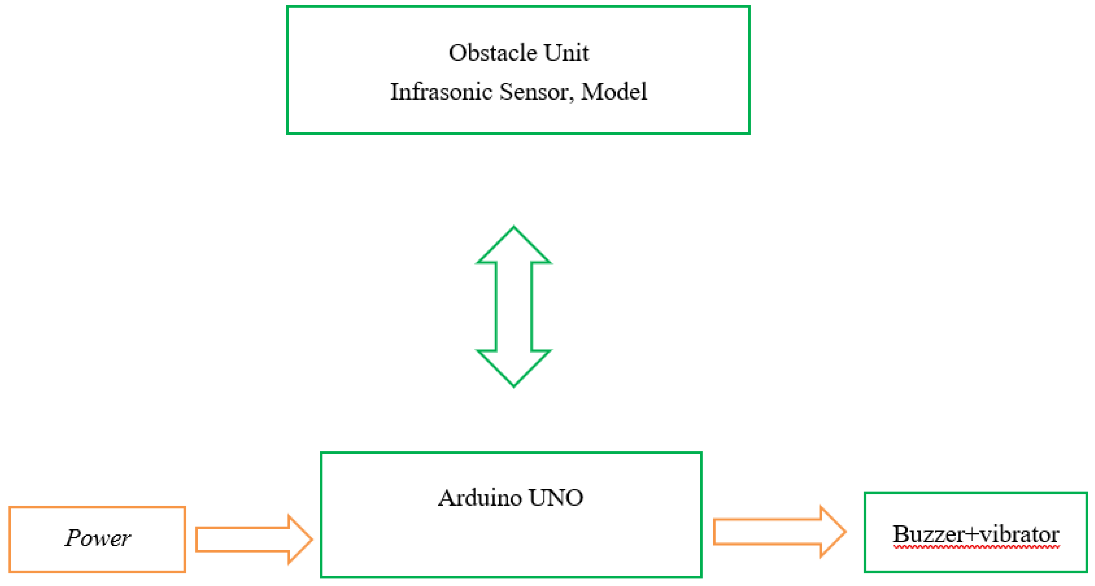
We will talk about the working principle in this section of the introduction. The gadget consist of an infrasonic sensor buzzer and Arduino UNO male to male cables. The block diagram of obstacles detector are given below:
Figure 1.
2 BLOCK DIAGRAM OF THE SYSTEM.
Figure 1.
2 BLOCK DIAGRAM OF THE SYSTEM.
We can see from the diagram above that the buzzer infrasonic sensor, and power supply are connected to the Arduino UNO. When an object enters the infrasonic sensor field of vision a command is sent to the Arduino UNO which then executes the command. As a result the Arduino UNO processes this command send it to the buzzer , and generates sound. Low frequency signals are used by infrasonic sensor to identify any obstructions in the way of blind people. When an obstruction in the path is near , the infrasonic sensor transmitter emit an infrasonic signal which causes the buzzer to vibrate more an emit high pitched noise.
1.3. Advantages of Projects:
There are allots of advantages of obstacle detector. Here we will discuss few of them.

The purpose of this obstacle detection system to enable a blind person to move more quickly by providing knowledge about the complex environment around them.

It is cheaper as compared to guiding dogs which are very expensive. It can be afforded by every poor impaired person.

This obstacle detector makes impaired people independent of other. Who depends totally on other for their life activities.

Due to their complete reliance on other people obstacle identification and detection is a key goal for electronic mobility aids for the unsighted person.

This device has been developed in order to enhance the independent mobility of blind individuals.

In this detector we use vibrator which produce sound and inform blind person about any hurdles in their path.

With the help of obstacle detector visually impaired people are able to achieve their goals in this modern word.

In this study we present a narrative frame work for obstacle detection and classification that will let blind people who are partially seeing traverse environments on their own.

The suggested obstacle detection model can be use independently. Due to the fact that it can quickly and accurately detect harmful moving object in complex environment without knowing the position of obstacle detector.
1.4. Description of Component:
1.4.1. Arduino Processor:
The fourteen digital input/outputs of the Arduino UNO microprocessor panel. Six of them can be utilized as input, and six of them are pulse width modulation (PWM) output. Additionally it has a USB port, a power outlet a reset button an ICP (in circuit serial programming) header and other components.
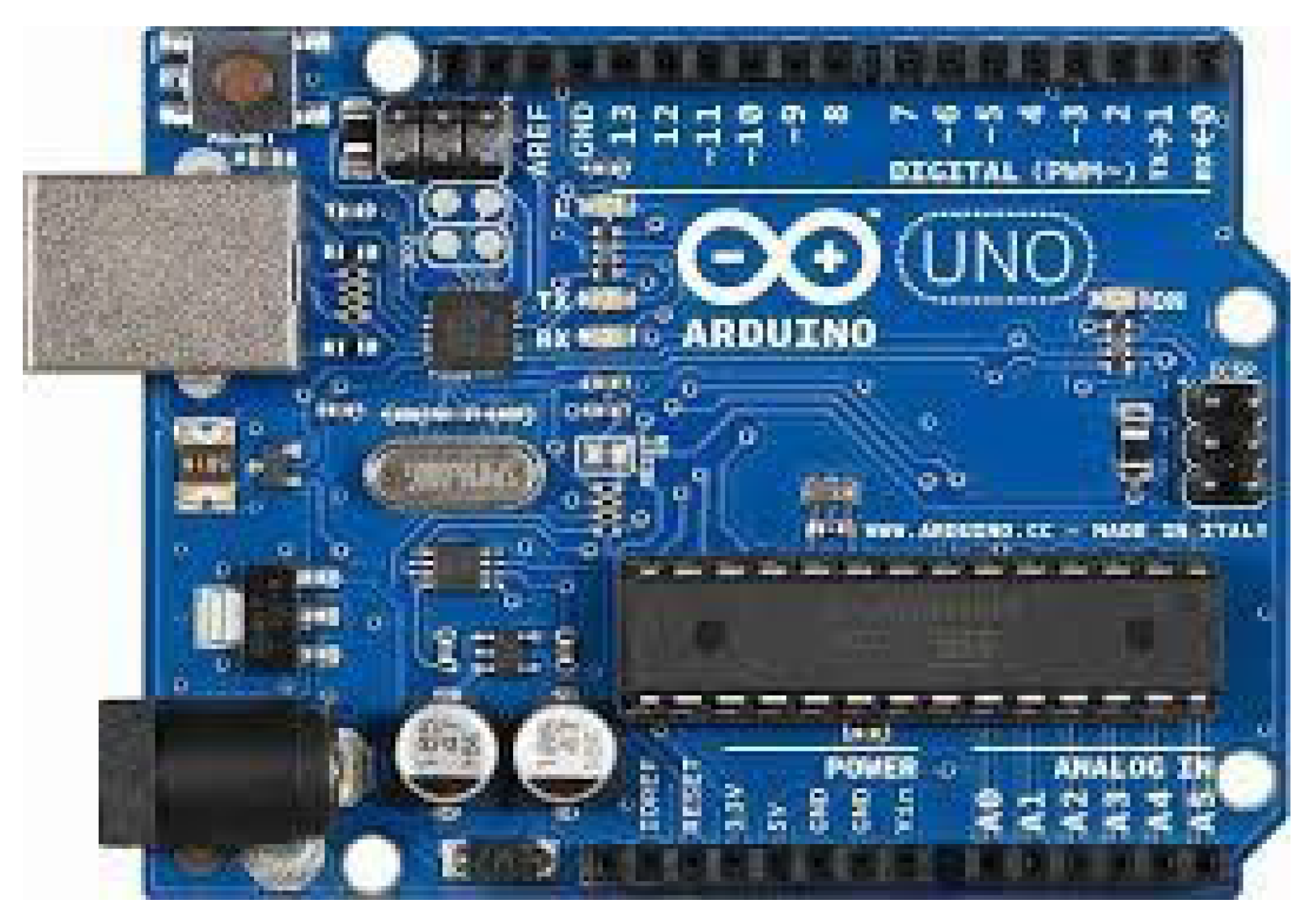
Figure 1.4.1.
1.4.2. 5. v Buzzer:
The Arduino buzzer is a signaling component. It could be electromechanical, mechanical or another type. It can serve as an alarm, timer and indicator.
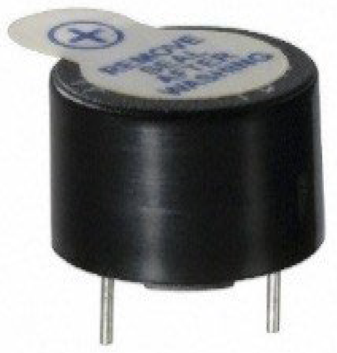
Figure 1.4.2
1.4.3. Infrasonic Sensor:
It either produces or detects infrasound energy. It is capable of measuring distance and locating objects without physically touching them. Transceivers, receivers, and transmitters are three subsets that they can be divided into. The range can vary depending on the sensor and object characteristics.

Figure 1.4.3
1.4.4. Arduino To Laptop Connector:
Using a USB cable and port, it connects an Arduino board to a laptop or PC ( this is the port closer to the DC power connector). Choose the serial port of duty from the tool menu (Arduino due programming port)
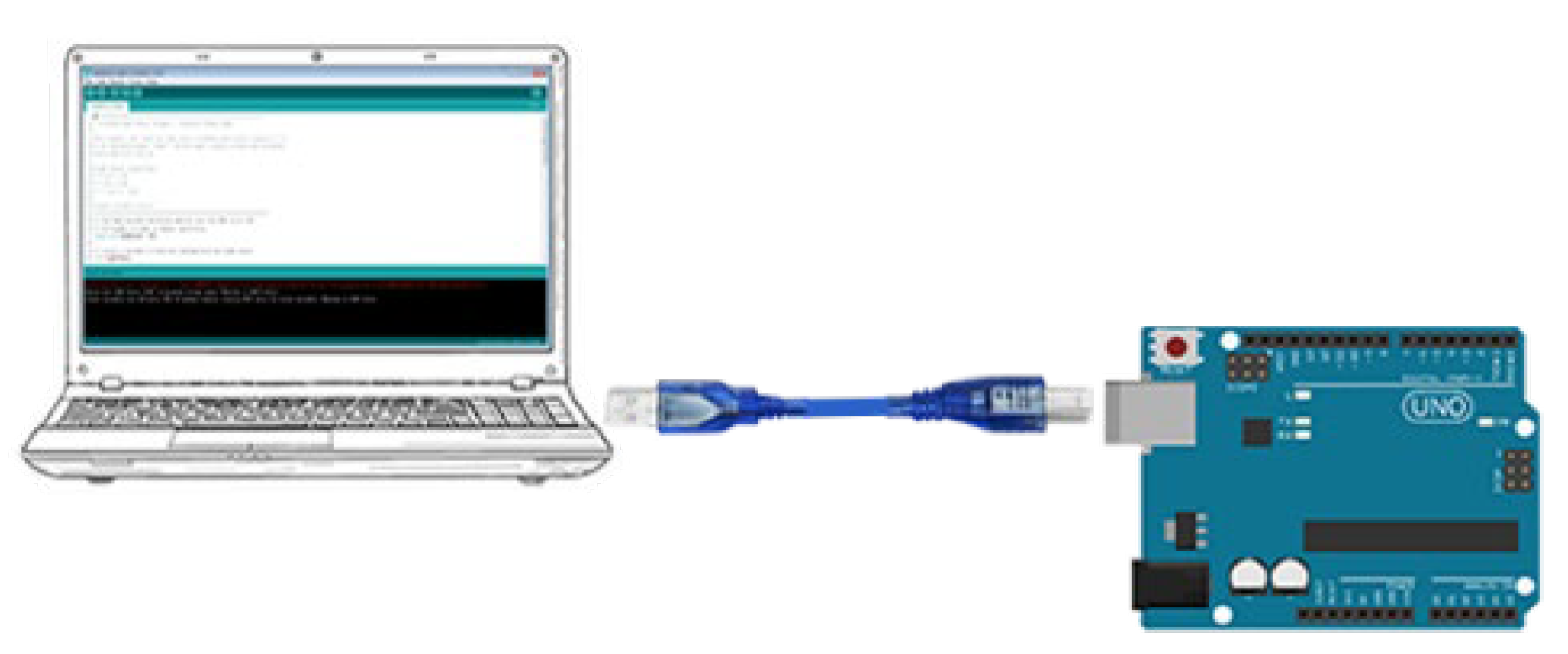
Figure 1.4.4
1.4.5. Male To Male Wire:
Male to male wire is a type of wire with bulging pin terminals that can readily plug into other wire devices.
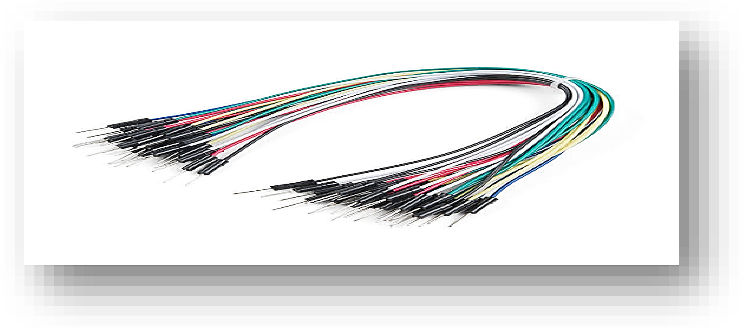
Figure 1.4.5
2.1. Literature Review:
In order to design and develop an obstacle detector using infrasonic sensor, extensive research on the obstacle detector is needed to be fulfilled. This section will discuss previous studies that have been accomplished by other researcher in the same region.
The movement of visually impaired people is limited by their inability to be familiar with their environment. According to 2021 survey of WHO about 78% of 297 million people who are reasonably to severely visually impaired and the 43 million persons who are blind are treatable. About 21 million out of 43 million are children of the age of 15 or less. From this survey we concluded the rate of blind people is increasing day to day. This clarified that in each 5 second somebody get blind in the world. About 82% blind students are unable to attain their school. We have arrange a research of obstacle detector and appropriation device for the sightless in this work bringing many low cost technologies to fulfill the needs of those who are blind . One of the key goal of this research project is to give user or visually impaired people real time pertinent navigation information so they can make timely precise judgments about which way take through space.
Using an infrasonic sensor and an Arduino UNO we proposed only a unique detection system in this study that enables the safe mobility of blind pedestrians in complicated surroundings. A lots of devices has been developed by different people for visually impaired people to improve their life. Here we will give a review to these previous frame work.
The research by Dakopoules et al. provides a comparative analysis of wearable technology for those with visual impairments. In this research paper classified under the visually replacement categorization , and our project falls under the subcategory of electronic travel aids, according to that definition (ETAS).
Two sonar based environmental imaging sensor known as the tri sensor and sonic guide are proposed in section 4. Information about detector barriers was provided by these sonic guide and tri sensor. The sonic guide is an ultrasonic echo locating device with binaural head mounting. The tri sensor gadget consist of a high resolution trail type spatial sensor. This tri sensor is built into a device that is worn on the head. The system is offered for sale in the marketplaces. Through stereo headphones the three sensors create an audio image with a 50 degree frontal field of vision. The tri sensor permits for the identification and localization of several objects in front of the user in 3D space up to distance of 5m.
For a visually challenged person with six degrees of freedom (DOF), the authors described a stereo vision system. It was used to forecast visually impaired users subsequent movements and to keep a local 3D map of the area around the users.
Additionally present in that group are sensory and walking companion. These systems use tones to alert users about obstacle coming in their way at a more distance from them than the length of a cane by detecting them and alerting them with a tone.
A portable indoor localization tool for visually challenged people is provided in by combining various sensory modalities. They specifically used an expanded kalman filter FKP) architecture to combine data from a 213 laser scanner, gyroscopes , and floor-mounted pedometer.
Even if Cy ARM takes a somewhat different technique, it is wearable and has a low coast. It employs ultrasonic sensors to determine the distance to the nearest obstruction before transmitting the information to the blind individual utilizing the rigidity of the fixed cable tied to the belt. The tension in the string directly relates to how far away from the obstacle the person is. The Cy ARM programmer provides a workable solution, however the way in which information is sent to the target audience does not fit his project, which lessens its beauty. Because this device cannot be used hands free , the user must continuously move it to check for obstacles.
The majority of approaches employing GPS information are stated in the work of loomis et al. who claim that the 20 meter limit for users or disabled persons using commercial GPS accuracy in good condition satellite condition is quite high. Particularly when they are wandering in unfamiliar places, can create potentially dangerous situations for those who are blind. In different GPS (DGPS), correction signals are broadcast to the mobility receiver in order to rectify its position, a GPS receiver at a know fixed point is used. Deferential correction, on the other hand, calls for a different receiver that is not available everywhere. The method described in that increases GPS accuracy by including useful information in the localization framework is an interesting.
The SUGAR system was just released in is a navigation system for blind people that employs a smart phone as an ultra-wide band (UWB also known as digital PULES wireless) and as a processing unit for location or positioning. In relation to VI- specific applications. Radar system employ UWB technology to communicate. There is a wireless technology called ultra wide band that allows for the long distance very low power transmission enormous data volume over several frequency bands in a radar system the system penetrates nearly all surfaces bat reflect off of farther away surfaces , the allowing for the detection of things hidden behind walls or other obstructions. VI user recive the warning instruction via auditory commands and acoustic cues.
This frame work is only compatible with setting that have ubisense UWB tags. Regularly wearing headphones prevents the wearers ears from being exposed to ambient infrasound.
The obstacle detection device I SONIC finds objects at its head height. With the help of an algorithm that reduces unwanted and confusing detections it alerted the user to the undesirable condition. Additionally it provides details like the colour of the objects and the uncharted environment.
Walker and Lindsey investigated the use of tailored non speech for blind people to navigate. The network’s limited coverage and high installation and maintenance costs, however are the main drawbacks.
An urban direction system based on electronic tags with spoken audio signals is described in point . The landmarks to which these tags can be connected are building entrances, bus stations, and elevators. Push hand held devices are what are utilized to activate a tag. The device’s little loud speaker then makes the spoken voice message audible.
The 3D smart phone used in for the aerial obstacle detection plan technique uses stereo vision to capture the scene’s 3D structure. The system tracks the VI user’s walking direction to detect any potentially hazardous obstructions along the road using magnetometer and accelerometer sensors. The system has been tried out on actual blind people, and it works well. Due to its sensitivity to any abrupt camera movement and lighting changes, its method is limited. Under these conditions, the tracking process con not be successfully completed.
A European initiative with seven partners created the Cognitive Aid System for Blind People (CASBLIP) system. The goal of this project is to create a system that can understand and manage real world data from many sources to offer mobility assistance for people with any type of visual impairment.
An assistance gadget based on depth information is suggested in . The system is built to recognize various dynamic barriers and convey this information which will help the user to navigate safely. The effectiveness of the approach was assessed with the aid of VI individuals in actual circumstances, as the authors note, because the system has a significantly decreased applicability.
This method is used in to recognize objects that are independently moving. The suggested system has the ability to do a 3D map reconstruction and calculate the camera’s ego motion as well as the numerous types of scene moments. The entire framework uses a CPU in outdoor area , and it is quite sensitive to changes in lighting, which have an impact on the depth map estimate and 3D reconstruction of the environment. It takes a lot of processing to create a scene model.
Tang and Beebe developed a two-way touch technology that offers directional guidance for blind people’s mobility in . It has a 49 electrode electro tactile display to give the blind user directional signals which help visually impaired people to improve their mobility areas.
Without any prior training a portable smart phone- based real time obstacle detection device for VI individuals is suggested. The authors use traditional computer vision techniques, such as colour histogram representation and edge detection, but the technology falls short of the hand free requirements set by V users, even though it is directional cues from the user, both affordable and unobtrusive.
The SONA sonic orientation navigation aid system makes use of similar idea. The SONA system was developed by the Georgia Institute of Technology in the years following 1979. SONA is a prototype environmental labeling system that performs navigation using radio-activated aural beacon.
A system of 36 electrodes that transmit electrical impulses to the tongue has recently been introduced by for the detection and adjustment of posture and stability for patients with balance impairments. Electronic guide dogs employ a human agent at the central facility, unlike Makinos who uses a mobile unit. This human agent speaks to the user to notify them of their location and other information .
Another orientation and navigation method that makes use of inductive loop radio signals is spoken landmarks. The signal transmission range of this device is 2 meters. The system notifies the user of the abstaining through spoken communication. This gadget is distinct from the radio frequency transmitters talking signs extremely short range and unidirectional design prevent exact object localization
3.1. Introduction:
We’ll briefly explain the materials utilized in this project in this section, as well as briefly go over how our project is really put together. We also conducted a survey in the Mardan district. Our survey’s objective is to determine the percentage of blind persons living in Mardan. Here in our project we will discuss the reasons for their blindness as well as the kind of device they used to detect obstacles. After that, we will conduct an experiment and show them our design model, and then we will contrast the outcomes of our device with those of earlier models. Prior to beginning our projects survey, we will first discuss the region in which we plan to structure our survey.
Climate can occasionally affect how a habitat is perceived. The profession will give us a sense of how wealthy or poor the folks are. After that, we will employ the content in our project in accordance with that. The level of literacy gives us a clear indication of whether or not people wish to better the lives of blind people. Geography will also advise us of a location’s suitability for blind people’s survival. Whether or not they have all the prerequisites in place.
3.2. Working Principal:
The majority of our lives are spent in our jobs as blind people. They are equally entitled to benefit from and enjoy modern technology. Due to their vision impairment they encounter numerous obstacles on their path to achievement. It is the duty of contemporary technology to provide them with the tools they need to appreciate nature’s beauty. There is a lot of equipment developed for these folks, yet some of it is highly expensive, of little utility, and falls short of their requirements. The gadget we suggested is inexpensive and offers solutions for all kinds of issues that arise in daily life. The model that we suggest is mounted on a hat. We select the cap. We chose the hat because it is very simple for people with disabilities to use. Additionally the obstruction will be visible at head height. To improve the aesthetics of our product, we will enclose all wiring inside the fabric of the caps. We will have a separate socket for the Arduino when it is placed in the cap. The front of the cap will have the infrasonic sensor to generate sound in the best possible way. Here, a buzzer will be placed in a specific area of the cap close to the ear in order to provide clear sound without interfering with everyday hearing. In the earlier section of this chapter we provided a brief explanation and detailed labeled illustrations of each component that we have used in our device.
We are now moving in the direction of our device’s operating system. The infrasonic sensor is made up of two components an infrasonic emitter and a receiver. With the help a power supply that powers all components, the emitter part will continuously emit infrasonic sound, which will be reflected from any obstacles it encounters. It will arrive at the receiver after consideration. If the range is three meters, the receiver will only pickup the infrasound that has been reflected. However, if the obstruction is more than three meters away, only receiver will get the signal, and our suggested device won’t react to it.
When a signal is received, the internal circuit converts it into an electric pulse before sending it to the Arduino processor. The obstacle’s distance is computed using the Arduino code we wrote. If the obstacle is farther away than 3 meters the signals are ignored and no further action is taken. If the obstacle is closer than 3 meters the signals are processed for further action and a pulse is generated to disturb the buzzer and cause it to make sound.
The buzzer’s sound has a purpose other than to signal the presence of an impediment it also keeps people’s minds engaged. The buzzer’s output changes depending on the instructions given by the Arduino processor. A weak signal is transmitted to the buzzer if the barrier is closer as a result the buzzer makes a sluggish sound that indicates the impediment is around 3 meters away. In contrast, a powerful signal is sent to the buzzer when the distance is closer which cause a crisp sound to be made.
We deduced from this that the sound of the buzzer is inversely related to the distance of the obstacle from the blind persons. The smaller the distance, the louder the buzzer will be, and vice versa. There are many other devices that can be used to detect obstacles that are coming a blind person’s way, but in such a situation, his/her mind does not function properly. This is the straight forward and thorough working upon which our proposed model is based. The mind will have to process some challenging instruction, which will take a lot of time. In this project we shall favour human thought over computer thought since it has two advantages:-
The ability to think clearly is essential for staying young for a long time.
The cost will drop due to the removal of unnecessary equipment, which is positive for the poor.
3.3. Material Used:
The material used in this design are listed below:
3.3.1. Bread Board:
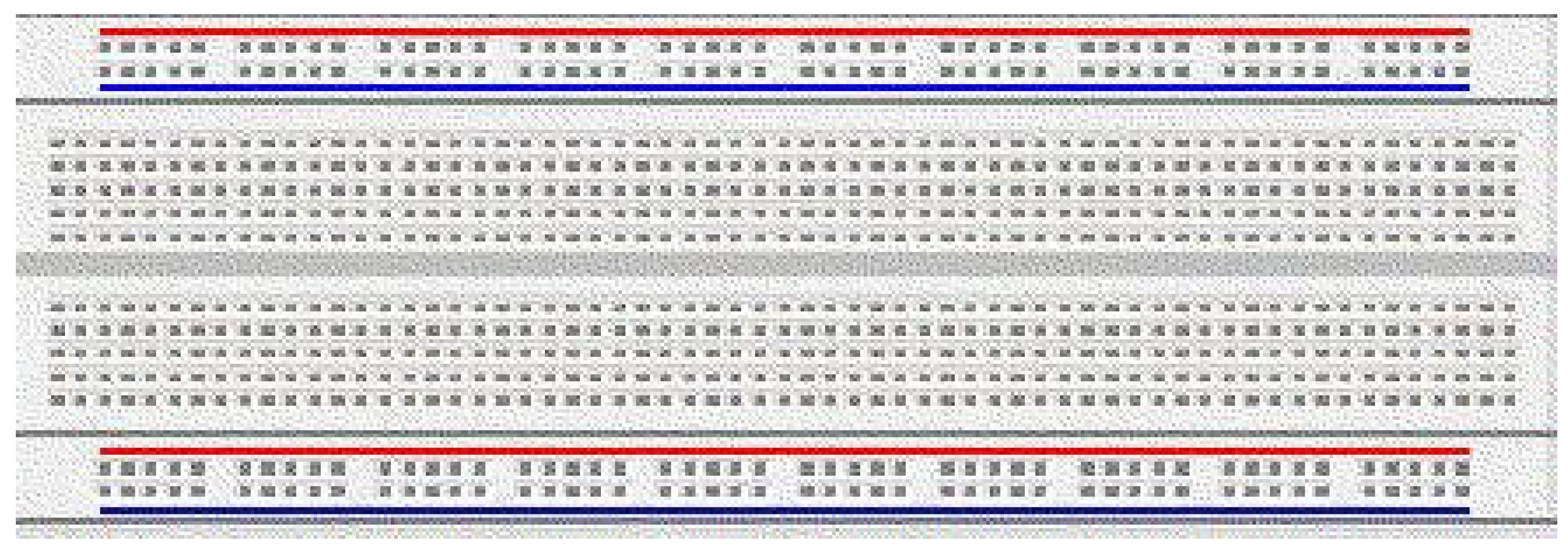
An electrical component holding board made of thin plastic is called a bread board. Before completing any types of circuits, it used to be swiftly built and tested. Bread Board have several holes in which components such as resistors and ICs are placed. A typical bread board is displaced below.
Figure 3.
3.1: Bread Board.
Figure 3.
3.1: Bread Board.
There are some metal strips below the holes that link the holes together. We can see from the diagram that the top and bottom holes are joined together horizentally and the holes located in the middle are joined vertically the diagram that is mentioned below makes this very clear.
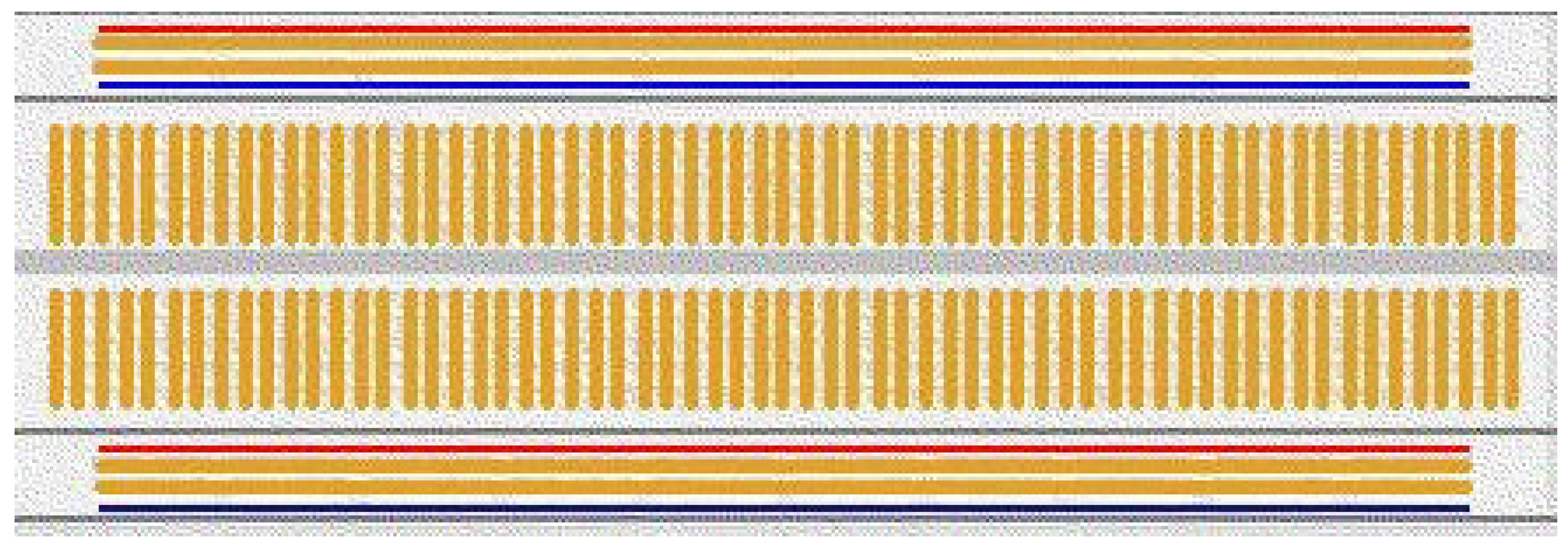
The components legs are inserted into the holes to link them to one another and then a connection is created between them using jumper wires. The holes located in the middle are utilized to join the electronic components, while the holes located in at the top and bottom are utilized for the supply of power. The device which we have prepared will be look as below:
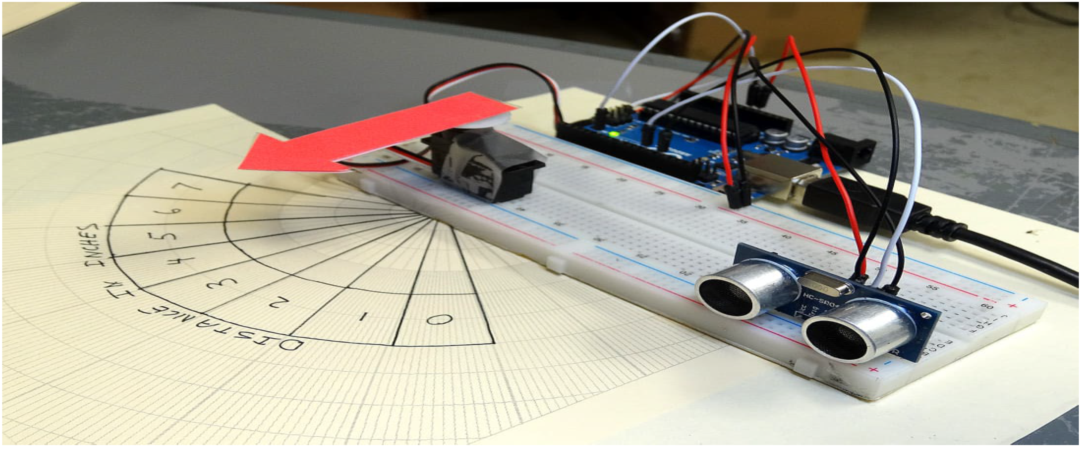
Figure 3.3.1: Range of the System
3.3.2. Arduino:
3.3.2.1. What is Arduino?
The microcontroller Arduino is constantly available for programming different types of circuit panel. Circuit panels can be basic or complex but all of them contain a microprocessor that can be programmed to perform certain task as required in the real world. The Arduino can communicate with a variety of outputs including LED’s motors and others as well as inputs and sensors. It is the greatest option for programmers who want to construct any hardware projects because of its varied capability.
Arduino was introduced by Massimo Banzi in 2005 as a mechanism for non engineers to access basic hardware creation projects. It was developed under a creative commons license which allows anyone to design their own board thanks to its open source programming. Hundreds of Arduino boards are available but the top and official model is called Arduino UNO.
The board with Arduino written on them are the official ones as shown in the figure below.
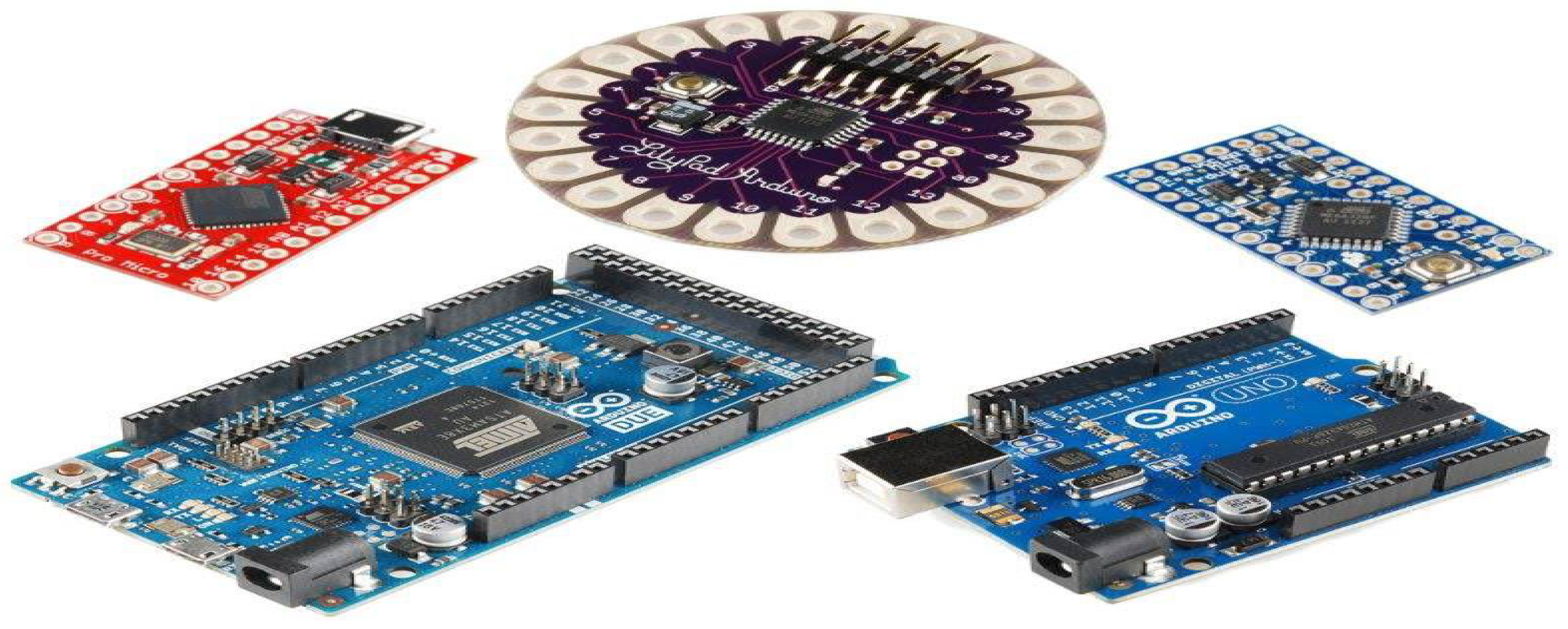
Figure no. 3.3.1.1.
3.3.2.2. Arduino UNO:
The Arduino UNO is one of the best and most popular Arduino models despite not being the first board to be released. It is actually the Arduino model that is used the most frequently and actively. We are major supporters of Arduino UNO because of its widespread use and the abundance of instruction that are available on line which make it simple to master and can produce one out of the rush below is the diagrammatic representation of the Arduino UNO.
Figure 3.
3.2.2: Arduino UNO Component Daigram.
Figure 3.
3.2.2: Arduino UNO Component Daigram.
The Arduino UNO parts are denoted by numbers in the picture below. The breakdown of each and every component is given below.
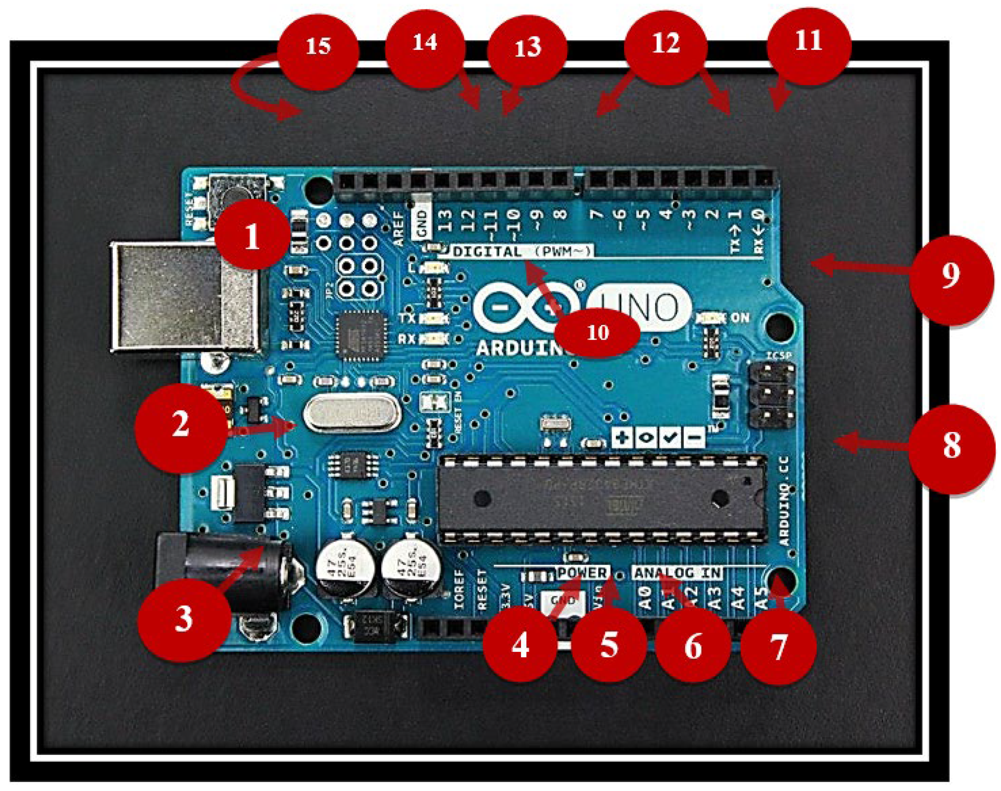
Figure 3.3.2.2: Arduino UNO Component Explanations Figure
The components name and function are as follow.
3.3.2.2.1. Male To Male Wire:
This part is used to power the Arduino and link it to a laptop so that a burning program may be run.
3.3.2.2.2. Voltage Regulator:
This component is used to controls the voltage we have supplied to the Arduino.
3.3.2.2.3. DC Power Barrel Jack:
This component is also used for power supply, however it does so with the help of a charger and a central power cord with 9mm diameter.
3.3.2.2.4(3.3). V Pin:
This component gives the Arduino the necessary 3.3 volt electricity.
3.3.2.2.55. V Pin:
This pin supplies the board with 5 volts of electricity.
3.3.2.2.6. Ground Pins:
On the board there are a number of ground pins but they all perform the same function.
3.3.2.2.7. Analog Pins:
These pins are used to change analog signals into digitals signals for transmission.
3.3.2.2.8. A Tmega Micro Controller:
In this place the programmers are kept. The Arduino brain as the saying goes.
3.3.2.2.9. Power LED Indicator:
When a power source is applied to the board, this light becomes turn.
3.3.2.2.10. TX/RX:
These have the ability to send and receive data LED’s.
3.3.2.2.11. PWM:
This component is used to minis on optical signal.
3.3.2.2.12. Digital Input/output:
Digital signals are inputted and outputted on pins 1 through 13 respectively.
3.3.2.2.13. AREF:
“A” stand for “Analog” and ‘REF’ stands for “reference” so AREF means “Analog reference” and it establishes same analog voltage as a reference.
3.3.2.2.14. Reset Button:
By doing this you can format the software that was burned the Arduino and reset it.
3.3.3. Arduino Power Supply:
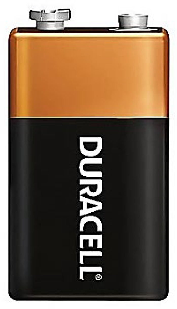
There are various methods for fueling the Arduino UNO which is required for functioning. The board id often powered by a computer connection, however if one wants to create a mobile project, they must utilize a 9v battery. Therefore we will utilize a 9V battery in our project.
Figure 3.
3.3: Arduino Power Supply.
Figure 3.
3.3: Arduino Power Supply.
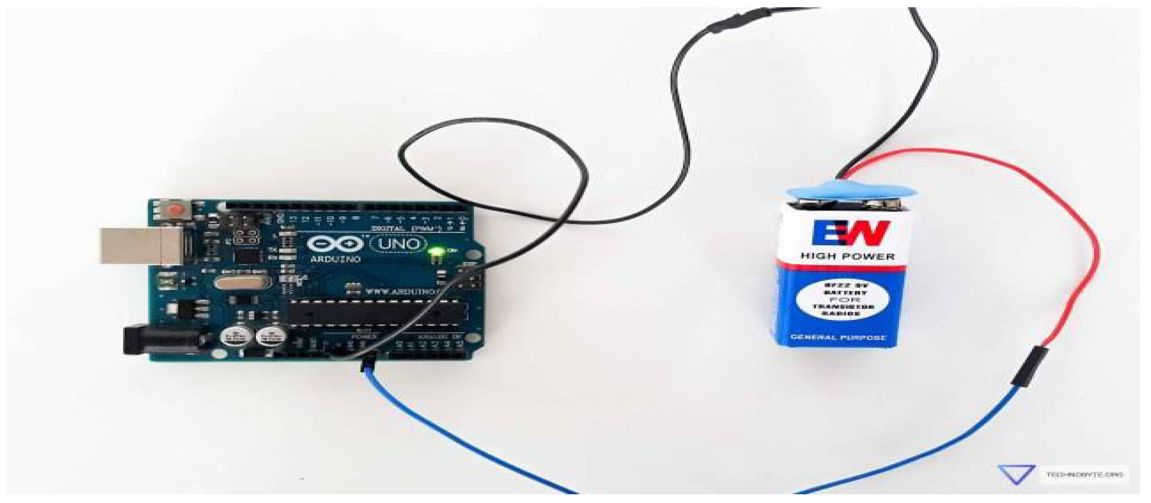
Most people refer to the battery as an alkaline battery. It uses zinc and manganese dioxide as electrolytes. It is made without cadmium and mercury to be environmentally friendly. It is designated as 9 volts and has a temperature range of -18 to 55 degrees. Most frequently , it weights 45g. it typically has a 21cm3 capacity. It can endure for up to five years at 21 degrees. With the aid of the provided connector, it is attached to the Arduino(fig).
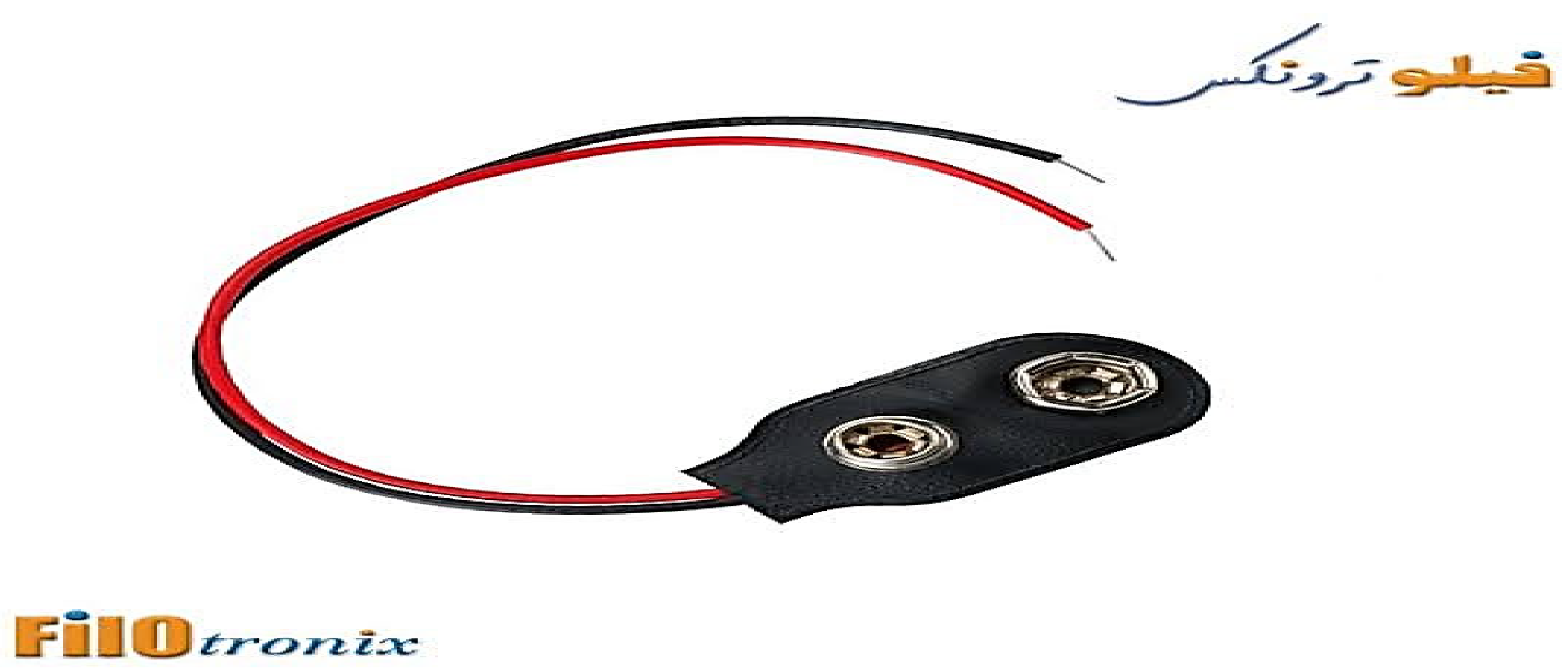
Figure 3.3.3: Arduino Power Supply Connector
The Arduino’s Vin and GND connector are linked to the battery’s positive and negative terminals, respectively. The connections for the battery and Arduino are shown in the diagram below.
3.3.4. Buzzer:
An electrical device called a buzzer produces an audible sound or alarm. It is made up of a tiny electromechanical component that, when turned on , emits a buzzing or buzzing – like sound.
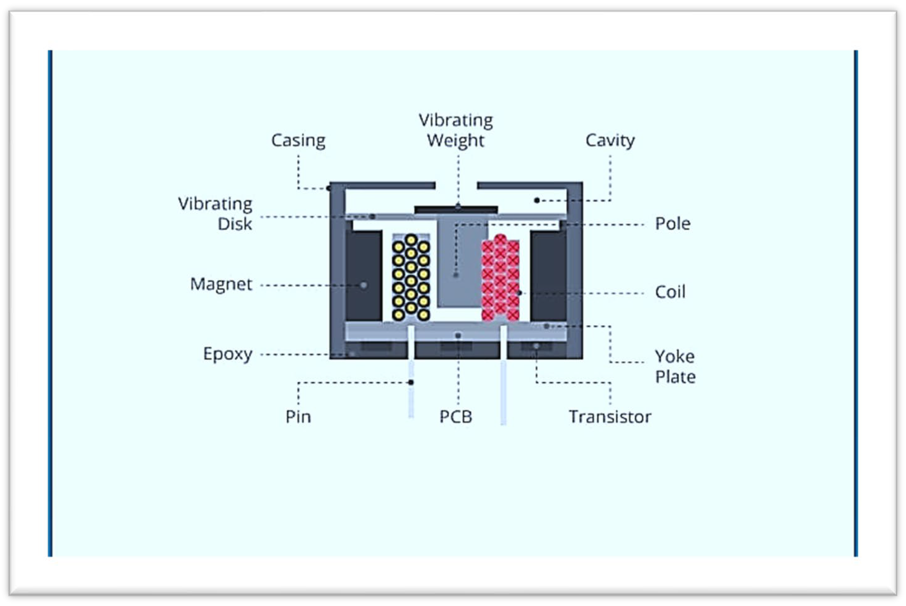
The coil produces a magnetic field when an electric current is introduced. A coil a diaphragm or magnetic plate and a power source make up the bulk of a buzzer. The diaphragm or plate is drawn to this magnetic field, which causes waves are created by the vibration and this distinctive buzzing noise. Different buzzer designs may be appropriate for different applications. Some buzzers are made to be small and integrated with other electronic devices, like electronic games, doorbells, and alarm clock. Others are more powerful and large making them idea for commercial uses or panic buttons. A typical electronic circuit is utilized to regulate the buzzer’s activation and deactivation. Sensors or other components or set off events can be attached to the circuit when it receivers a signal, creating the desired audio.
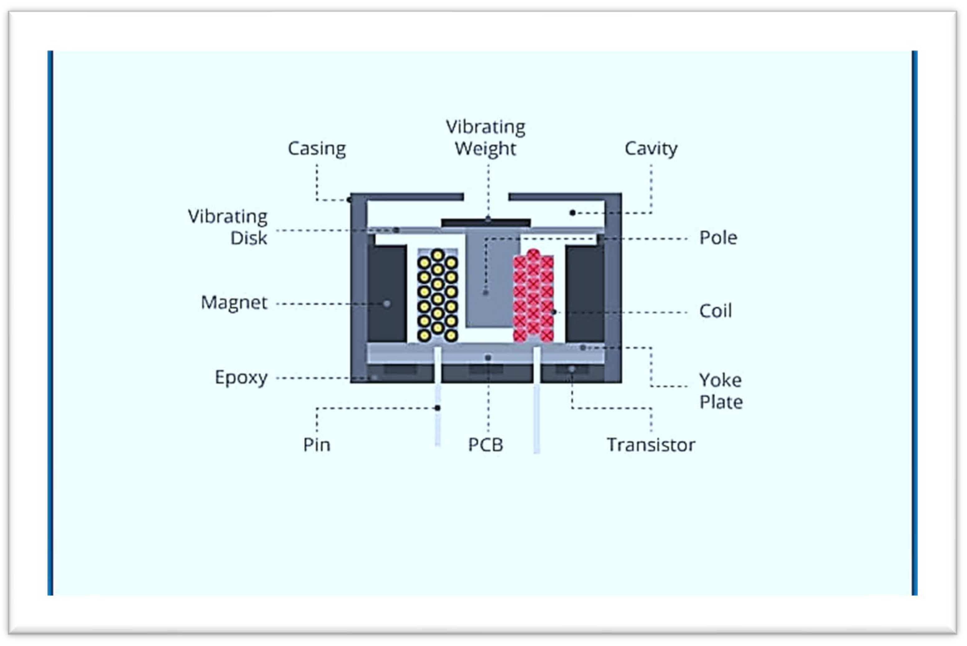
Figure 3.3.4: Megnatic Buzzer Structure
3.3.4.1. Magnetic Buzzer Structure:
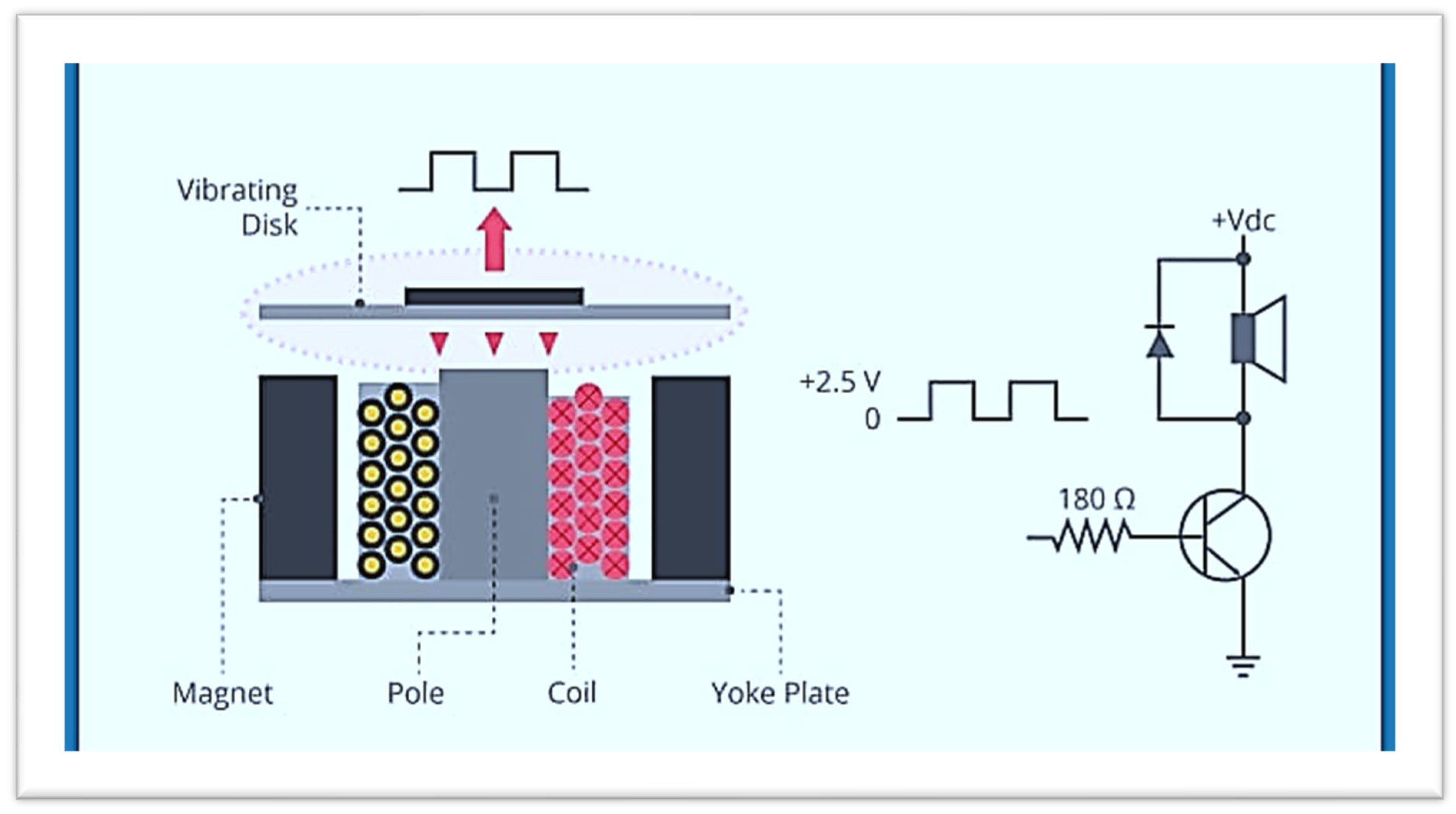
The common magnetic buzzer’s construction is depicted in the figure below. The magnetic buzzer’s transistor serves as the driving circuit. When a DC power supply is applied, indicator use transistors to generate a tone.
In conclusion, an electromechanical buzzer is a tool that transforms electrical energy into audible sound waves. It is made up of a coil, a plate or diaphragm, and a power source. The coil creates a magnetic field when an electric current is applied which causes the diaphragm or plate to vibrate and make the distinctive buzzing sound.
Figure 3.
3.4.1: Megnatic Buzzer Structure.
Figure 3.
3.4.1: Megnatic Buzzer Structure.
3.3.4.2. Application:
Buzzers are mostly used for recognition and alarm reasons through many vital industries.
3.3.5. Jumper Wires:
A bundle of electrical wires in a cable that has connectors or pins at both ends ( or , on occasion, just tinned ends) is knows as a jumper wire or jumped. It is frequently employed to link the components of a breadboard or test circuit inside, with other pieces of machinery or equipment or both without soldering jumper wire in a gauge with solid tips. Individual jumper wires end connection are attached by squeezing them into slot provided on a breadboard the header connector of a circuit board for a piece of test equipment. Jumper wires come in a variety of colours but their operation is unaffected by their colour; instead their use in a circuit is solely indicated by the colour designated for that function such as GND.
3.3.5.1. Types of Jumper Wires:
There are three types of jumper wires which are given below:
male-to-male,
male-to-female
female-to-female.
The difference between each is in the end points of the wire
3.3.5.1.1. Male to Male Jumper Wire:
You may be easily create your own circuit on a bread board using the male to male jumper wire. These cable are flexible and have prototyping board connectors on both ends. The jump cable is perfect for building circuit between your micro controller and the bread board on the bots.
Specification:

cable length: 20 cm

Quantity : 10 wires

Random colour : white / yellow / orange / blue / black / red

Material : plastic + tin plating copper

Figure no3.3.5.1.1.
3.3.5.1.2. Male to Female Jumper Wire:
In response to numerous requests we have now stocked this male to female jumper it comes in a bag of 10 wires. These wires can be used to quickly and easily link prototype boards to most commercially available boards. On a 0.1 (100 mil or 2.54mm) header, several jumpers can be connected adjacent to one another. A circuit connecting components are its wires small wire ducts called jumper wire can be used to join parts together on breadboard or in other places. This wirers male and female header allow for solder less connection that is simpler it has pin on one side and socket on the other.
Feature:
Specification:

Figure no3.3.5.1.2.
3.3.5.1.3. Female To Female wire:
They are straight forward wires with connector pin at each ends that can be used to link two places together. These are frequently used in conjunction with breadboard and other prototyping tools to make it simple to modify a circuit as necessary female to female jumper wires that may be plugged into any other development board to link the female header pin of an Arduino or other development board to another development board.
40 strip female to female jumper wire each cable length is 20 cm or 8- inch.
It has sockets on both ends and are mainly used as extension wires.
Feature:
Specification:
Length: 10cm, 20cm, 30cm
Colour: white, blue, gray, brown, orange ,black, red, yellow, green, purple (each cable includes 4 of each colour)
Fit breadboard.

Figure no 3.3.5.
3.3.6. Infrasonic Sensor:
The term “infrasonic” is refers to the study of sound waves that are below the threshold at which humans can hear them. Its frequency range from 0.1 Hz to 20 Hz.
Infrasonic has a wide range of uses including earth quick monitoring rock and petroleum exploitation in the earth obstacle detection, nuclear explosion detection, potential plane explosion detection etc.
The invention related to an infrasonic sensor comprising a metal shell. A metal wire enclosure is arranged on the inner side of the top end of the metal shell a tapered resonant disc is arranged under the metal wire enclosure. A piezoelectric chip is arranged under the tapered resonant disc above a chip mounting structure is arranged in the bracket. The bracket is arranged at the bottom of the metal shell an anode lead terminal and a cathode lead terminals are arrange at the bottom end of the metal shell are provided with an anode lead and the cathode lead respectively. The infrasonic sensor is simple structure, small in size high in sensitivity and well responsive to low frequency infrasound.
Working:
The working of infrasonic sensor is based on the principle of reflection of sound wave having audible range below then the human audible frequency range.
3.3.6.1. What is Infrasound?
Low status sound, or infrasound refers to sound waves with a frequency below the threshold of human audibility. The frequency is below the range of human hearing perception.
3.3.6.2. Infrasonic Frequency Range Sepctrum:
These sound waves, whose frequency fall between 20Hz and 20 KHz, are audible to human ears. Infrasonic sound on the other hand has a frequency lower than 20 Hz which is why it is invisible to human senses.
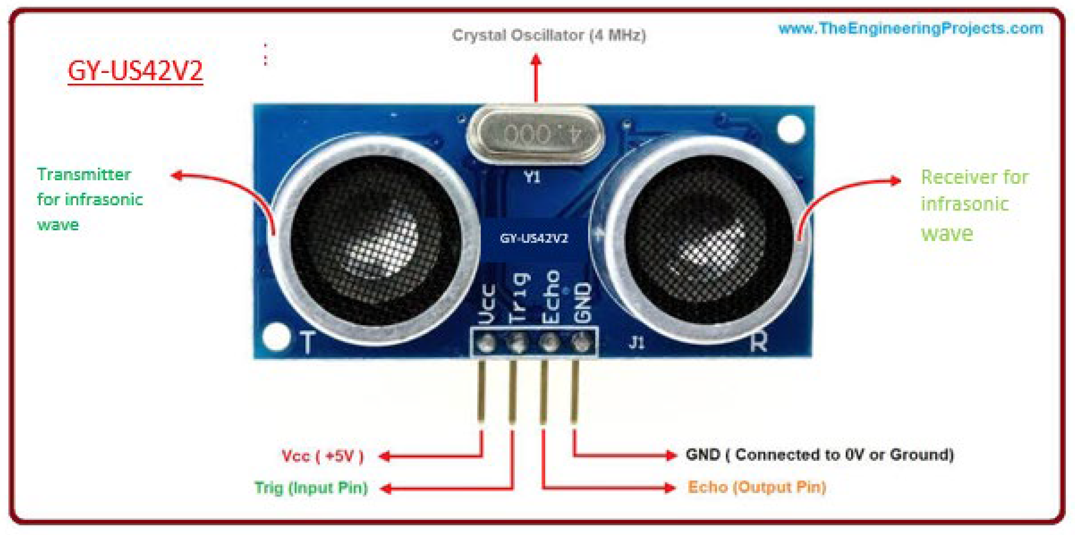
3.3.6.3. GY-US42 Sensor:
A prominent type of sensor used in robotics and automation projects is the GY-US42 sensor. Such as the GY-US42 infrasonic distance sensor. It can be readily integrate with microcontroller like Arduino and uses infrasonic waves to calculate distance on the basis of infrasonic range GY-US42 sensor functions. It uses to return to source after impacting an item. The distance between the sensor and objected is calculated by computing the time of flight.
Feature:
Its measuring range is from 20cm to 4m.
Working temperature is 20 centigrade to 65 centigrade.
Working current is 9 mA.
Its size are 35mm x 23mm x28mm
It has four pins.
Explanation of the pins:
Now its pins configuration are described below:
3.3.6.3.1. VCC (Voltage Common Collector):
The GY-SU42 sensor is powered by this pin. To provide the voltage needed for the sensor to function, connect it to the Arduino board’s 5V pin.
3.3.6.3.2. GND (Ground):
This pin is linked to the Arduino board’s ground (GND) pin. It completes the circuit and gives the sensor’s operation a reference point.
3.3.6.3.3. Trig(Trigger):
Utilizing this pin can activate the infrasonic sound beats. It is used for Tx.
3.3.6.3.4. Echo Output:
When the mirror signal is detected this pin vibrates. The pulse expenditure varies in direct proportion to how long it takes for the transmitted signal to be noticed it is used for Rx.
4.1. Result And Discussion:
According to the study findings, 18.6% of participants use a white cane when venturing out on their own. Although there are various obstacles ban their way, motorbike and bicycle accidents are the most common ones that 54% of individuals encounter in their familiar environments, such as schools and residences. The majority of participants stated that they had never used an electronic travel aid but that they were really excited about it since it would be very helpful to them. The majority of participants were interested in the inexpensive electronic detector.
With the use of an Arduino microcontroller and infrasonic sensor, we have developed a model of obstacle detection for blind individuals that is affordable and accessible to all the societies’ needy and underprivileged members. This project only goal is to empower blind people to be self-sufficient members of society. This type is simple to prepare and can be tailored to the wearer. Since there are a lot of blind people in the poor region of Mardan, we used the Arduino board and other components as cheaply as we could. It is useful in identifying many obstacles especially those that are in the way of your mind.
The head impact is a hazardous incident that could cause long-term memory loss. Therefore, avoiding head collision is the participants top priority. This is the impetus behind our decision to mount the sensor at eye level.
Although our proposed model can detect a significant number of obstacles it does not provide information on the type of obstruction, its direction , shape, size, or any relevant details. Additionally, it only pick up on object that there 1 to 1.5 meters in front of it. Additionally, it does not offer any assurance of safety for the impending barrier; instead, it merely detects it, leaving the blind person to cope with it on their own.
The alarm system functions well because the sound intensity changes in direct proportion to the distance from the obstacle , but it will not be advantageous for those who have hearing problems. In addition the code that we installed in the Arduino was kept as straight forward as possible. The infrasonic sensor is also of the highest caliber and reasonably priced. The connection are so straight forward that even a layperson can fix it after it has been damaged.
One benefit of our preferred model is that it does not need any sophisticated electronics knowledge which would be confusing to a blind pedestrians. It is incredibly easy to use and only requires two or three days of practice before it can continue to charge the world for the blind.
5.1. Future Work
Blind people can now live independently in society thanks to numerous recent advances in the field. Additionally , we made an attempt that complied with Mardan district’s blind resident need. In our created model we favors the following future suggestion.

Interviews with additional people may be conducted and the poll may include additional questions about night vision, blind people in particular profession etc. To obtain a more precise estimate of the number of blind persons living in the district of Mardan and its related population.

Future work could verify both the safety and the accuracy of our created model which only detector barriers detection obstruction.

Future models may included technology that could help people with a variety of defects, such as both blind and deaf people, etc. Our model is only intended for blind peoples with the rest of the body parts operating normally.

Our created model demonstrated the detection only from the front. Future research could ensure that the detection is done in a well designed manner from the left, right and back sides as well.

The alarm system might use some enhancements. Similar to using audio recordings in the local language to train a visually impaired people.

Additionally, it is advantageous to change the 9v battery with a rechargeable battery.
References
- Rodríguez, Alberto, et al. "Assisting the visually impaired: obstacle detection and warning system by acoustic feedback." Sensors 12.12 (2012): 17476-17496. [CrossRef]
- Rodríguez, Alberto, et al. "Assisting the visually impaired: obstacle detection and warning system by acoustic feedback." Sensors 12.12 (2012): 17476-17496. [CrossRef]
- Rodríguez, Alberto, et al. "Assisting the visually impaired: obstacle detection and warning system by acoustic feedback." Sensors 12.12 (2012): 17476-17496. [CrossRef]
- Mocanu, Bogdan, Ruxandra Tapu, and Titus Zaharia. "When ultrasonic sensors and computer vision join forces for efficient obstacle detection and recognition." Sensors 16.11 (2016): 1807. [CrossRef]
- Mocanu, Bogdan, Ruxandra Tapu, and Titus Zaharia. "When ultrasonic sensors and computer vision join forces for efficient obstacle detection and recognition." Sensors 16.11 (2016): 1807. [CrossRef]
- Rodríguez, Alberto, et al. "Assisting the visually impaired: obstacle detection and warning system by acoustic feedback." Sensors 12.12 (2012): 17476-17496. [CrossRef]
- Rodríguez, Alberto, et al. "Assisting the visually impaired: obstacle detection and warning system by acoustic feedback." Sensors 12.12 (2012): 17476-17496. [CrossRef]
- Mocanu, Bogdan, Ruxandra Tapu, and Titus Zaharia. "When ultrasonic sensors and computer vision join forces for efficient obstacle detection and recognition." Sensors 16.11 (2016): 1807. [CrossRef]
- L.Fang, P.Antsakaklis, L.Montestruque, M.McMickell, M.Lemmon, Y.Sun, H.Fang, I.Koutroulis, M.Haenggi, M.Xie, and X.Xie “Design of a wireless assisted pedestrian dead reckoning system-the navmote experience ,” IEEE transastions on instrumentation and Measurment, vol. 54, no. 6, pp. 2342-2358, 2005. [CrossRef]
- Rodríguez, Alberto, et al. "Assisting the visually impaired: obstacle detection and warning system by acoustic feedback." Sensors 12.12 (2012): 17476-17496. [CrossRef]
- Mocanu, Bogdan, Ruxandra Tapu, and Titus Zaharia. "When ultrasonic sensors and computer vision join forces for efficient obstacle detection and recognition." Sensors 16.11 (2016): 1807. [CrossRef]
- Jose, Joao Tiago Pereira Nunes. Real-time path and obstacle detection for blind persons. Universidade do Algarve (Portugal), 2010.
- Mocanu, Bogdan, Ruxandra Tapu, and Titus Zaharia. "When ultrasonic sensors and computer vision join forces for efficient obstacle detection and recognition." Sensors 16.11 (2016): 1807. [CrossRef]
- Mocanu, Bogdan, Ruxandra Tapu, and Titus Zaharia. "When ultrasonic sensors and computer e3vision join forces for efficient obstacle detection and recognition." Sensors 16.11 (2016): 1807. [CrossRef]
- Hoang, Van-Nam, et al. "Obstacle detection and warning system for visually impaired people based on electrode matrix and mobile Kinect." Vietnam Journal of Computer Science 4 (2017): 71-83. [CrossRef]
- Rodríguez, Alberto, et al. "Assisting the visually impaired: obstacle detection and warning system by acoustic feedback." Sensors 12.12 (2012): 17476-17496. [CrossRef]
- Mocanu, Bogdan, Ruxandra Tapu, and Titus Zaharia. "When ultrasonic sensors and computer vision join forces for efficient obstacle detection and recognition." Sensors 16.11 (2016): 1807. [CrossRef]
- Dunai, Larisa Dunai, et al. "Obstacle detectors for visually impaired people." 2014 International Conference on Optimization of Electrical and Electronic Equipment (OPTIM). IEEE, 2014. [CrossRef]
- Hoang, Van-Nam, et al. "Obstacle detection and warning system for visually impaired people based on electrode matrix and mobile Kinect." Vietnam Journal of Computer Science 4 (2017): 71-83. [CrossRef]
|
Disclaimer/Publisher’s Note: The statements, opinions and data contained in all publications are solely those of the individual author(s) and contributor(s) and not of MDPI and/or the editor(s). MDPI and/or the editor(s) disclaim responsibility for any injury to people or property resulting from any ideas, methods, instructions or products referred to in the content. |
© 2023 by the authors. Licensee MDPI, Basel, Switzerland. This article is an open access article distributed under the terms and conditions of the Creative Commons Attribution (CC BY) license (http://creativecommons.org/licenses/by/4.0/).
 The purpose of this obstacle detection system to enable a blind person to move more quickly by providing knowledge about the complex environment around them.
 It is cheaper as compared to guiding dogs which are very expensive. It can be afforded by every poor impaired person.
 This obstacle detector makes impaired people independent of other. Who depends totally on other for their life activities.
 Due to their complete reliance on other people obstacle identification and detection is a key goal for electronic mobility aids for the unsighted person.
 This device has been developed in order to enhance the independent mobility of blind individuals.
 In this detector we use vibrator which produce sound and inform blind person about any hurdles in their path.
 With the help of obstacle detector visually impaired people are able to achieve their goals in this modern word.
 In this study we present a narrative frame work for obstacle detection and classification that will let blind people who are partially seeing traverse environments on their own.
 The suggested obstacle detection model can be use independently. Due to the fact that it can quickly and accurately detect harmful moving object in complex environment without knowing the position of obstacle detector.







 cable length: 20 cm
 Quantity : 10 wires
 Random colour : white / yellow / orange / blue / black / red
 Material : plastic + tin plating copper


 Interviews with additional people may be conducted and the poll may include additional questions about night vision, blind people in particular profession etc. To obtain a more precise estimate of the number of blind persons living in the district of Mardan and its related population.
 Future work could verify both the safety and the accuracy of our created model which only detector barriers detection obstruction.
 Future models may included technology that could help people with a variety of defects, such as both blind and deaf people, etc. Our model is only intended for blind peoples with the rest of the body parts operating normally.
 Our created model demonstrated the detection only from the front. Future research could ensure that the detection is done in a well designed manner from the left, right and back sides as well.
 The alarm system might use some enhancements. Similar to using audio recordings in the local language to train a visually impaired people.
 Additionally, it is advantageous to change the 9v battery with a rechargeable battery.


