Submitted:
19 December 2023
Posted:
20 December 2023
You are already at the latest version
Abstract
Keywords:
1. Introduction
- Built practical SEM, SAVM, and IAVM simulation models for the AFE rectifiers.
- Appropriate initialize the AFE rectifiers in case of lack of command control signals.
- Limit the inrush current during the starting period using a pre-charge circuit.
- Provide a robust close-loop control strategy with a unit power factor.
- Improve the dead-time impact on the rectifier using the proposed advanced AVM.
- Fully consider the effect of switching devices’ voltage drops in the models.
- Compare the performance of the models to verify the proposed IAVM operation.
2. AFE Rectifier Models
2.1. Switched (PWM) Model
2.2. Dynamic Average-Value Model
3. Proposed Improved AVM
3.1. Enhanced Dead-Time Distortion Model
3.2. Improved Startup Procedure
4. Results
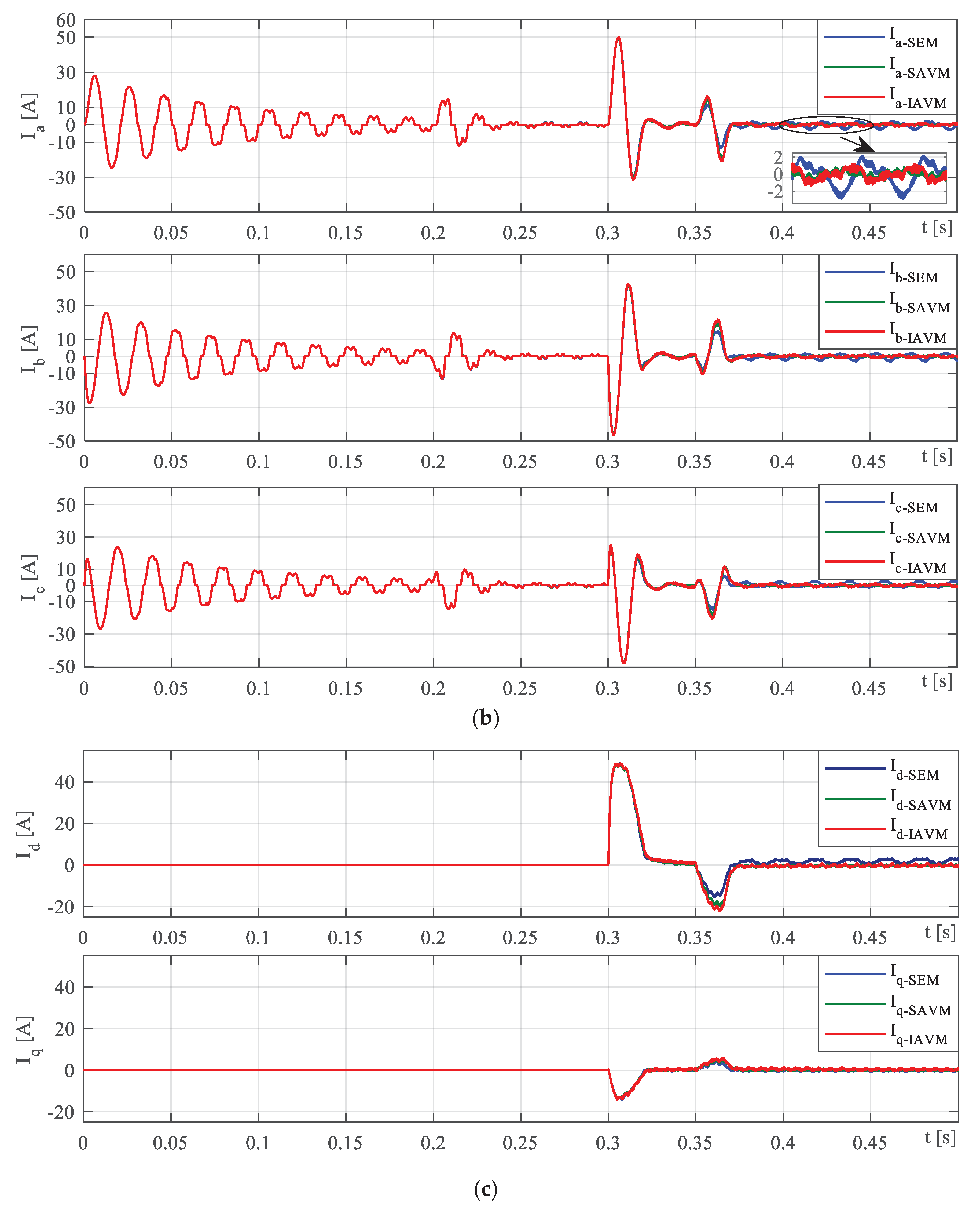
4.1. Case 1: Startup Performance
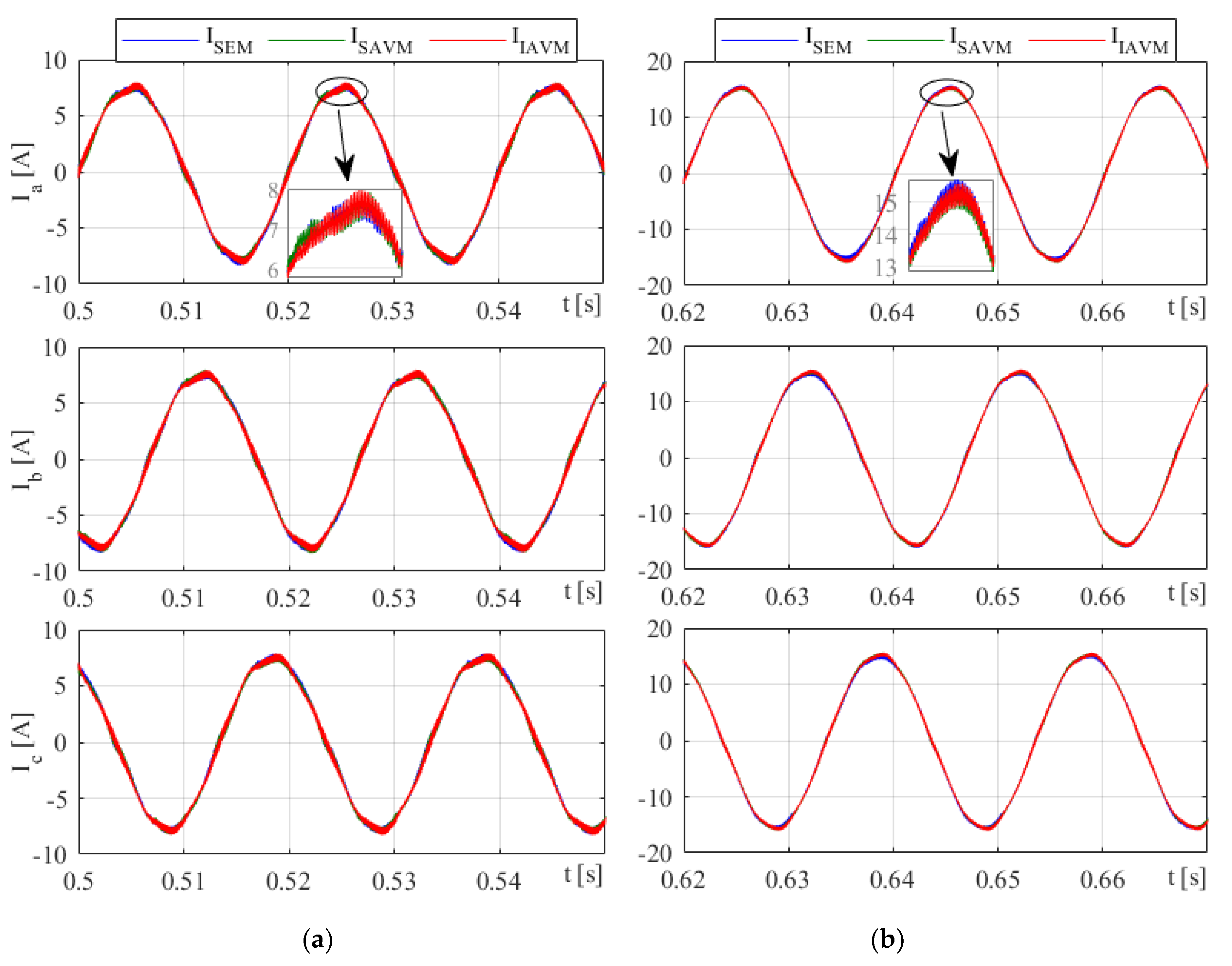
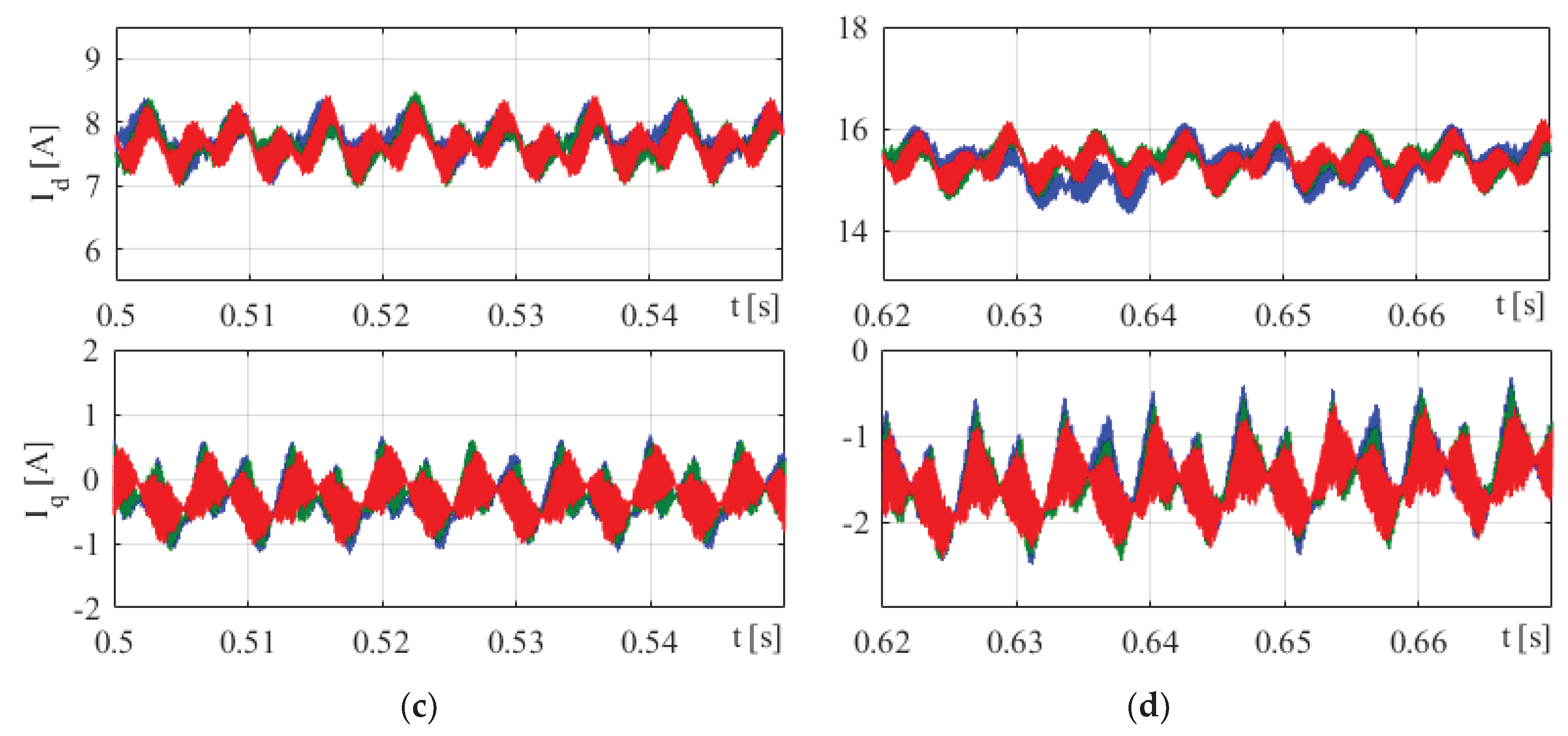
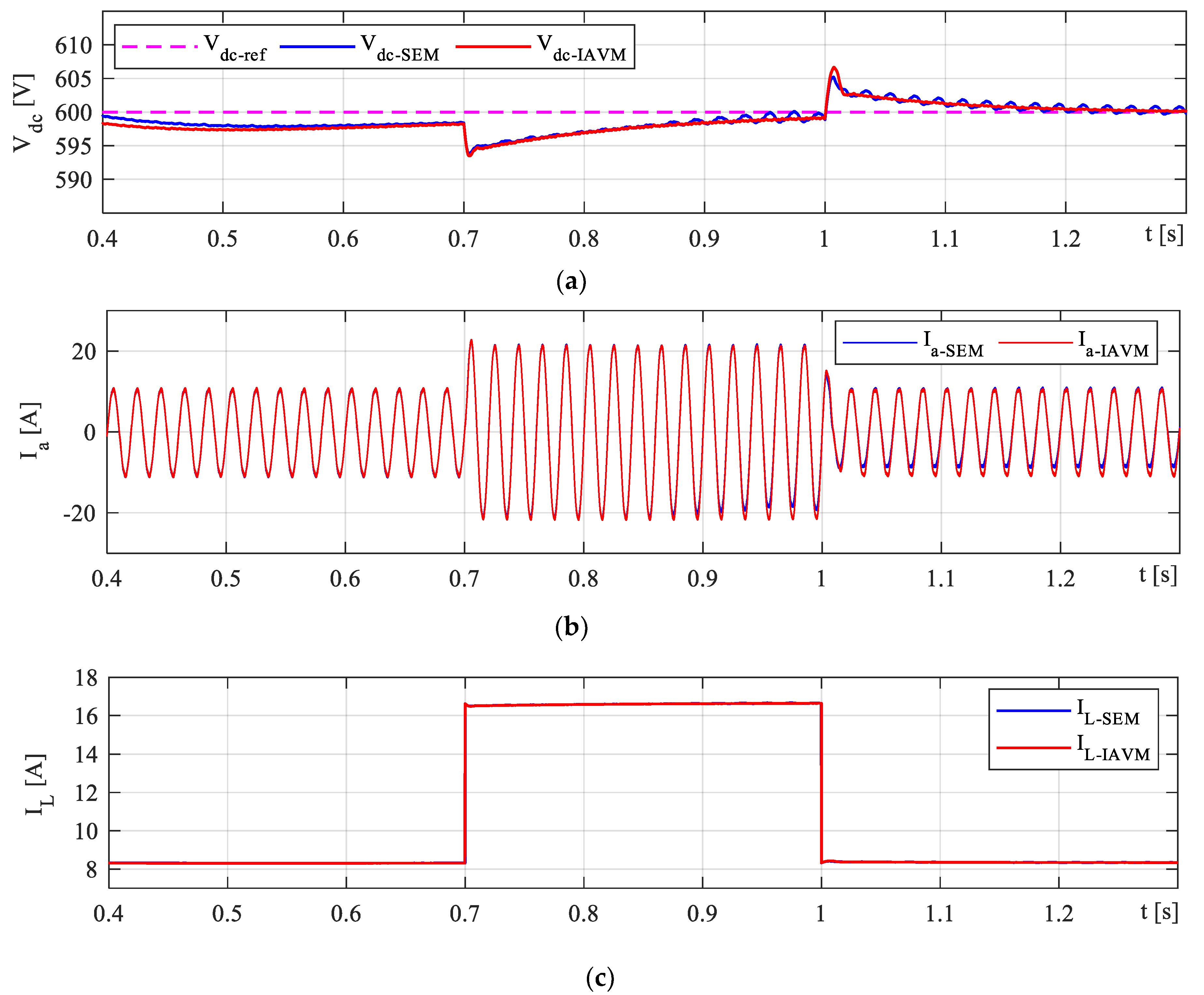
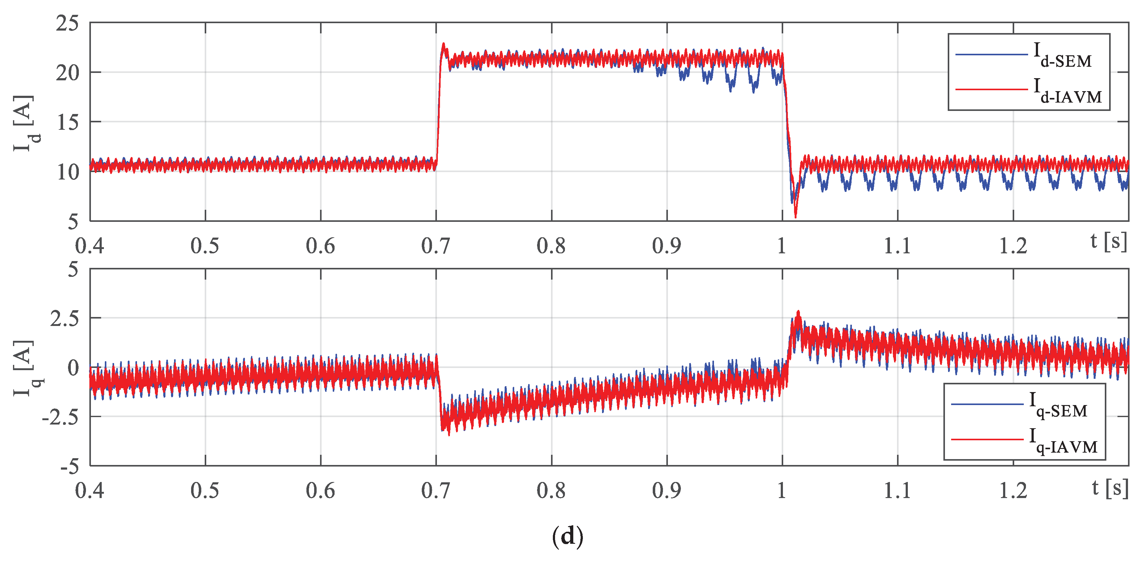
4.2. Case 2: Load Responces
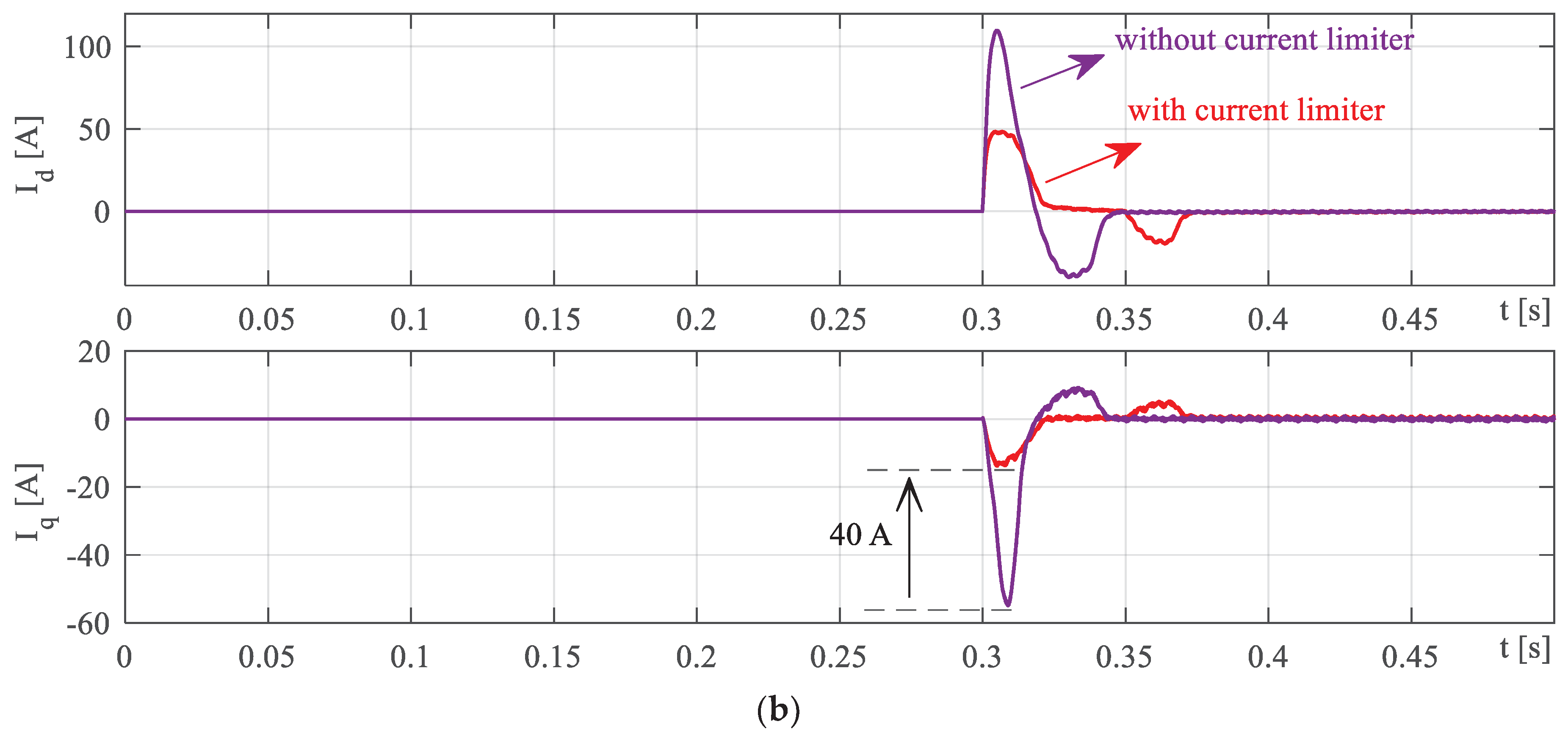
4.3. Case 3: Transient Performance
5. Conclusions
Acknowledgments
Conflicts of Interest
References
- Buticchi, G.; Lam, C.-S.; Xinbo, R.; Liserre, M.; Barater, D.; Benbouzid, M.; Gomis-Bellmunt, O.; Pamos-Paja, C.A.; Kumar, C.; Zhu, R. The role of renewable energy system in reshaping the electrical grid scenario. IEEE Open J. Ind. Electron. 2021, 2, 451–468. [Google Scholar] [CrossRef]
- Ebadpour, M. A Multiport Isolated DC-DC Converter for Plug-in Electric Vehicles Based on Combination of Photovoltaic Systems and Power Grid. In Proceedings of the 12th Power Electronics, Drive Systems, and Technologies Conference (PEDSTC), Tabriz, Iran; 2021. [Google Scholar]
- Guerrero, J.M.; Blaabjerg, F.; Zhelev, T.; Hemmes, K.; Monmasson, E.; Jemei, S.; Comech, M.P.; Granadino, R.; Frau, J.I. Distributed generation: toward a new energy paradigm. IEEE Ind. Electron. Mag. 2010, 4, 52–64. [Google Scholar] [CrossRef]
- Esenboğa, B.; Demirdelen, T. Soft-Switching Smart Transformer Design and Application for Photovoltaic Integrated Smart City Power Distribution. Sustainability 2023, 15, 32. [Google Scholar] [CrossRef]
- Ebadpour, M.; Sharifian, M.B.B. Cascade H-Bridge Multilevel Inverter with Low Output Harmonics for Electric/Hybrid Electric Vehicle Applications. Int. Rev. Electr. Eng. (IREE) 2012, 7, 3248–3256. [Google Scholar]
- Planès, T.; Delbecq, S.; Pommier-Budinger, V.; Bénard, E. Modeling and Design Optimization of an Electric Environmental Control System for Commercial Passenger Aircraft. Aerospace 2023, 10, 260. [Google Scholar] [CrossRef]
- Alduraibi, A.; Yaghoobi, J.; Solatialkaran, D.; Zare, F. A Modular Power Converter With Active Front-End System to Mitigate Harmonics in Distribution Networks. IEEE Trans. Emerg. Sel. Topics Power Electron. 2021, 9, 1725–1735. [Google Scholar] [CrossRef]
- Sannino, A.; Bollen, M.H.J.; Svensson, J. Voltage tolerance testing of three-phase voltage source inverters. IEEE Trans. Power Deliv. 2005, 20, 1633–1639. [Google Scholar] [CrossRef]
- Gao, F.; Bozhko, S. Modeling and impedance analysis of a single DC bus-based multiple-source multiple-load electrical power system. IEEE Trans. Transp. Electrific. 2016, 2, 335–346. [Google Scholar] [CrossRef]
- Kim, Y.-W.; Sul, S.-K. Stability Analysis of Active Front End and Permanent Magnet Synchronous Generator with Back EMF-Based Sensorless Control for DC Marine Vessels. IEEE Trans. Power Electron. 2023, 38, 5411–5421. [Google Scholar] [CrossRef]
- Zhaksylyk, A.; Rasool, H.; Abramushkina, E.; Chakraborty, S.; Geury, T.; El Baghdadi, M.; Hegazy, O. Review of Active Front-End Rectifiers in EV DC Charging Applications. Batteries 2023, 9, 150. [Google Scholar] [CrossRef]
- Bagheri, N.; Alipour, H.; Mohammadian, L.; Beiza, J.; Ebadpour, M. A Multiport Isolated Resonant LLC Converter for Grid-Tied Renewable Energy Powered Bidirectional EV Charger. Int. J. Ind. Electron. Control. Optim. 2023, 6, 37–48. [Google Scholar]
- Prakash P, P.; Kalpana, R.; Singh, B.; Bhuvaneswari, G. Design and Implementation of Sensorless Voltage Control of Front-End Rectifier for Power Quality Improvement in Telecom System. IEEE Trans. Ind. Appl. 2018, 54, 2438–2448. [Google Scholar] [CrossRef]
- Gong, Z.; Wu, X.; Dai, P.; Zhu, R. Modulated Model Predictive Control for MMC-Based Active Front-End Rectifiers under Unbalanced Grid Conditions. IEEE Trans. Ind. Electron. 2018, 66, 2398–2409. [Google Scholar] [CrossRef]
- Zhang, Z.; Wei, L.; Yi, P.; Cui, Y.; Murthy, P.S.; Bazzi, A.M. Conducted Emissions Suppression of Active Front End (AFE) Drive Based on Random Switching Frequency PWM. IEEE Trans. Ind. APPL. 2020, 56, 6598–6607. [Google Scholar] [CrossRef]
- Zare, F.; Davari, P.; Blaabjerg, F. A Modular Active Front-End Rectifier With Electronic Phase Shifting for Harmonic Mitigation in Motor Drive Applications. IEEE Trans. Ind. Appl. 2017, 53, 5440–5450. [Google Scholar] [CrossRef]
- Malinowski, M.; Kazmierkowski, M.P.; Trzynadlowski, A.M. A comparative study of control techniques for PWM rectifiers in ac adjustable speed drives. IEEE Trans. Power Electron. 2003, 18, 1390–1396. [Google Scholar] [CrossRef]
- Malinowski, M.; Kazmierkowski, M.P.; Hansen, S.; Blaabjerg, F.; Marques, G. Virtual-flux-based direct power control of three-phase PWM rectifiers. IEEE Trans. Ind. Appl. 2001, 37, 1019–1027. [Google Scholar] [CrossRef]
- Cano, J.M.; Jatskevich, J.; Norniella, J.G.; Davoudi, A.; Wang, X.; Martinez, J.A.; Mehrizi-Sani, A.; Saeedifard, M.; Aliprantis, D.C. Dynamic Average-Value Modeling of Direct Power-Controlled Active Front-End Rectifiers. IEEE Trans. Power Deliv. 2014, 29, 2458–2466. [Google Scholar] [CrossRef]
- Gendrin, M.; Gauthier, J-Y.; Lin-Shi, X. A Predictive Hybrid Pulse-Width-Modulation Technique for Active-Front-End Rectifiers. IEEE Trans. Power Electron. 2017, 32, 5487–5496. [Google Scholar] [CrossRef]
- Song, Z.; Tian, Y.; Chen, W.; Zou, Z.; Chen, Z. Predictive Duty Cycle Control of Three-Phase Active-Front-End Rectifiers. IEEE Trans. Power Electron. 2016, 31, 698–710. [Google Scholar] [CrossRef]
- Hou, C-C. A Multicarrier PWM for Parallel Three-Phase Active Front-End Converters. IEEE Trans. Power Electron. 2013, 28, 2753–2759. [Google Scholar] [CrossRef]
- Wiechmann, E.P.; Burgos, R.P.; Holtz, J. Active Front-End Converter for Medium-Voltage Current-Source Drives Using Sequential-Sampling Synchronous Space-Vector Modulation. IEEE Trans. Ind. Electron. 2003, 50, 1275–1289. [Google Scholar] [CrossRef]
- Divakar, Dwivedi, P.; Bose, S.; Pandey, S. Comparative Analysis of PI Control with Anti-Windup Schemes for Front-end Rectifier. In Proceedings of the IEEE First International Conference on Smart Technologies for Power, Energy and Control (STPEC), Nagpur, India, 2020.
- Cittanti, D.; Gregorio, M.; Bossotto, E.; Mandrile, F.; Bojoi, R. Full Digital Control and Multi-Loop Tuning of a Three-Level T-Type Rectifier for Electric Vehicle Ultra-Fast Battery Chargers. Electronics 2021, 10, 1453. [Google Scholar] [CrossRef]
- Chiniforoosh, S.; Jatskevich, J.; Yazdani, A.; Sood, V.; Dinavahi, V.; Martinez, J.; Ramirez, A. Definitions and applications of dynamic average models for the analysis of power systems. IEEE Trans. Power Deliv. 2010, 25, 2655–2669. [Google Scholar] [CrossRef]
- Yazdani, A.; Iravani, R. A unified dynamic model and control for the voltage-source converter under unbalanced grid conditions. IEEE Trans. Power Deliv. 2006, 21, 1620–1629. [Google Scholar] [CrossRef]
- Ebadpour, M.; Radmand, F. Hyper-plane sliding mode control of non-minimum phase grid-connected zeta converter. In Proceedings of the 12th Power Electronics, Drive Systems, and Technologies Conference (PEDSTC), Tabriz, Iran, 2021.
- Nikkhajoei, H.; Iravani, R. Dynamic model and control of ac-dc-ac voltage-source converter system for distributed resources. IEEE Trans. Power Deliv. 2007, 22, 1169–1178. [Google Scholar] [CrossRef]
- Lau, W.H.; Zhou, B.; Chung, H.S.H. Compact analytical solutions for determining the spectral characteristics of multicarrier-based multi-level PWM. IEEE Trans. Circuits Syst. I, Reg. Papers. 2004, 51, 1577–1585. [Google Scholar] [CrossRef]
- Chierchie, F.; Stefanazzi, L.; Paolini, E.E.; Oliva, A.R. Frequency analysis of PWM inverters with dead-time for arbitrary modulating signals. IEEE Trans. Power Electron. 2014, 29, 2850–2860. [Google Scholar] [CrossRef]
- Ahmed, S.; Boroyevich, D.; Wang, F.; Burgos, R. Development of a new voltage source inverter (VSI) average model including low-frequency harmonics. In Proceedings of the 25th Annual IEEE Appl. Power Electron. Conf. Expo. (APEC), California, USA; 2010. [Google Scholar]
- Guha, A.; Narayanan, G. Average modeling of a voltage source inverter with dead-time in a synchronous reference frame. In Proceedings of the IEEE Innov. Smart Grid Technol.-Asia (ISGT Asia), Bangalore, India; 2013. [Google Scholar]
- Banerji, A.; Patil, A.; Patil, S.; Pakhare, A.; Ugale, R.T. Design, analysis and fast tuning of active front end rectifier controller with comparative performance evaluation. In Proceedings of the IEEE International Conference on Power Electronics, Drives and Energy Systems (PEDES), Jaipur, India; 2022. [Google Scholar]
- Hou, C-C. ; Cheng, P-T. Experimental verification of the active front-end converters dynamic model and control designs. IEEE Trans. Power Electron. 2011, 26, 1112–1118. [Google Scholar] [CrossRef]
- Grandi, G.; Loncarski, J. Evaluation of current ripple amplitude in three-phase PWM voltage source inverters. In Proceedings of the International Conference-Workshop Compatibility and Power Electronics, Ljubljana, Slovenia; 2013. [Google Scholar]
- Ebadpour, M.; Jamshidi, M.; Talla, J.; Hashemi-Dezaki, H.; Peroutka, Z. Digital Twin Model of Electric Drives Empowered by EKF. Sensors 2023, 23, 2006. [Google Scholar] [CrossRef]




| AFE parameters | |||||||||
| IGBT Module | Vdc [V] | Vf (IGBT || D) [V] | Cdc [mF] | Tsw [s] | td [s] | ||||
| Fs400R07A1E3 | 600 | 1.5 | 4.7 | 1e-4 | 2e-6 | ||||
| Ac side parameters | |||||||||
| Vgrid (L-L) [Vrms] | Fs [Hz] | Ls [mH] | Cs [F] | Vout [V] | |||||
| 380 | 50 | 10 | 5 | 600 | |||||
| Controller gains | |||||||||
| DC voltage controller | Kp = 2.6 || Ki = 20.8 | ||||||||
| d-axis current controller | Kp = 31.72 || Ki = 157.44 | ||||||||
| q-axis current controller | Kp = 31.72 || Ki = 157.44 | ||||||||
| AFE Rectifier Model | SEM | SAVM | IAVM |
|---|---|---|---|
| THD% for 3.6 kW load | 5.14 | 4.96 | 4.78 |
| THD% for 7.2 kW load | 2.55 | 2.78 | 2.5 |
Disclaimer/Publisher’s Note: The statements, opinions and data contained in all publications are solely those of the individual author(s) and contributor(s) and not of MDPI and/or the editor(s). MDPI and/or the editor(s) disclaim responsibility for any injury to people or property resulting from any ideas, methods, instructions or products referred to in the content. |
© 2023 by the authors. Licensee MDPI, Basel, Switzerland. This article is an open access article distributed under the terms and conditions of the Creative Commons Attribution (CC BY) license (http://creativecommons.org/licenses/by/4.0/).


