
You are currently viewing a beta version of our website. If you spot anything unusual, kindly let us know.
Preprint
Article
Optimizing Rebar Consumption and Cutting Waste in Column Reinforcement: Integrated Mechanical Couplers and a Special-Length-Priority Minimization Algorithm
Altmetrics
Downloads
178
Views
9
Comments
0
A peer-reviewed article of this preprint also exists.


This version is not peer-reviewed
Abstract
The construction of reinforced concrete (RC) structures inevitably consumes an excessive number of rebars, leading to significant cutting waste and carbon emissions. Extensive research has been conducted to minimize this issue and its consequences; however, these methods consistently consume a substantial number of rebars. This includes a previous study that utilizes the lap splice position optimization and special-length rebar concept without considering the lapping zone regulation. Moreover, conventional lap splices pose inherent drawbacks that could jeopardize the structural integrity of RC members. In contrast, mechanical couplers eliminate the need for rebar lapping, effectively reducing rebar consumption. This research aims to evaluate the impact of an integrated mechanical coupler and special-length-priority minimization algorithm on the reduction in rebar consumption and cutting waste in RC columns, achieving near-zero cutting waste. To validate the effectiveness of the proposed algorithm, it was applied to the column rebars of an RC building. The results revealed a significant reduction in ordered rebar consumption by 18.25%, accompanied by substantial reductions in cutting waste (8.93%), carbon emissions (12.99%), and total costs (10.81%) compared with a previous study. The outcomes provide the industry with insights into further reducing rebar consumption and its related consequences. Applying the proposed algorithm to various construction projects will further amplify the corresponding benefits.

Keywords:
Subject: Engineering - Civil Engineering
1. Introduction
The construction of reinforced concrete (RC) structures inevitably consumes an excessive number of rebars and generates rebar cutting waste, with a projected range of 3-5% during the planning phase and an actual range of 5-8% during on-site realization [1]. Furthermore, the manufacture of rebars requires a tremendous amount of energy, which contributes to carbon emissions, thus posing a threat to the environment. In 2020, the global construction industry consumed 14 billion m3 of concrete [2], generating 53.9 million tons of cutting waste and emitting 188.92 million tons of CO2, resulting in a loss of USD 55.12 billion.
Conventional lap splicing with confining reinforcement, commonly used to connect adjacent rebars for decades [3,4], is one of the major contributors to waste and carbon emission issues in the industry. Lap splices necessitate longer lapping lengths, especially for larger-diameter rebars in high-rise buildings, and they have to be positioned following building codes, which augment rebar consumption and waste. Lap splice efficacy is dependent on the bonding strength between the concrete and rebars, which is reflected in the lap splice length. Moreover, investigations assert that adequate concrete cover, tensile strength, and transverse reinforcement ensure the performance of lap splices [5,6]. Building code regulations mandate specific positions or zones for lap splices, yet construction sites often find it difficult to follow these regulations and therefore disregard them [6]. Disregarding the regulation does not necessarily lead to structural failure. Although diverse optimization methods have been investigated, including cutting pattern and lap splice position optimization [7,8], their efforts have been limited to the adoption of stock-length rebars and building code regulations regarding lap splice position. As a result, it is difficult to reduce rebar cutting waste to below 5%, even with great effort.
In response to the disadvantage of stock-length rebars, researchers have introduced the use of special-length rebars to reduce cutting waste. The utilization of special-length rebars has been demonstrated to effectively minimize rebar cutting waste for beam elements, achieving waste reductions of less than 3% [9]. Despite the benefits of utilizing lap splice position flexibility and special-length rebars, column elements fabricated with this approach still exhibit substantial rebar consumption, even when zone regulations are not considered.
In addition, the application of conventional lap splicing has several drawbacks, including rebar congestion, increased rebar waste, higher costs, and impaired structural integrity [4,10,11,12,13,14,15]. The emergence of mechanical splices or couplers shed light on this issue. Couplers can connect adjacent rebars with significantly shorter lengths. They achieve greater strength than the rebar, efficiently transferring rebar tensile forces and maintaining structural integrity and stability compared to lap splices. Thus, couplers consume significantly less rebars and, eventually, less waste. It is expected that a significant reduction in rebar consumption and waste will also reduce costs and carbon emissions.
1.1. Rebar consumption and cutting waste
The global concrete volume reached 14 billion m3 in 2020 [2]. The extensive usage of concrete and rebars accounts for 65% of the CO2 emissions from the construction sector, with rebars alone responsible for 60% of this [16]. Research has established a rebar-to-concrete consumption ratio of 0.077 tons/m3 [1], indicating that the global concrete volume above corresponds to 1.078 billion tons of rebars. Considering a 5% cutting waste rate, this equates to 53.9 million tons of rebar cutting waste and 188.92 million tons of carbon emissions. Integrating these findings with a rebar price of USD 900/ton [17], a unit of rebar–carbon emissions of 3.505-ton-CO2/ton [18], and a carbon price of USD 75/ton-CO2 [19] implies a potential loss of USD 62.68 billion.
Previous research has been primarily centered on the usage of stock-length rebars to identify the most optimal rebar combination that generates the least amount of cutting waste. Nonetheless, the approach still generates a significant amount of cutting waste. Table 1 summarizes numerous studies that have attempted to optimize rebar cutting waste utilizing stock-length rebars. Additionally, investigations [7,8] also combined stock-length rebars with lap splice position optimization per the related regulation provided by building codes and failed to reduce the cutting waste to below 5%.
Faced with the challenge posed by stock-length rebars and their consequential high cutting waste, researchers and industry have actively explored alternative solutions, including special-length rebars. The use of special-length rebars enables the rebar lengths to be adjusted to fit the specific circumstances of a construction project, as they are supplied in 0.1 m increments. Previous research, as summarized in Table 2, confirms the effectiveness of special-length rebars in minimizing cutting waste, enabling the achievement of near-zero cutting waste. Nevertheless, their utilization remains limited to medium- and large-scale construction projects.
1.2. Rebar splicing methods
The need for lap joints on reinforced concrete (hereinafter, RC) structures arises due to various factors, including the limited length of the supplied rebar, variations in rebar diameter, and challenges related to transportation [13]. Although conventional lap splicing has long been considered a reliable and effective method for rebar splicing, it has several drawbacks that limit its applicability. These drawbacks include increased rebar consumption and waste, rebar congestion, a higher cost, and unsuitable use in the plastic hinge region [4,10,11,15]. Moreover, several studies [12,15,26] have highlighted that the adoption of lap splices may lead to the over-reinforcement of the section, reduced ductility, and ultimately a change in the structure’s deformation capacity. Ductility plays a vital role in averting sudden collapse due to brittle failure during seismic events [27]. Additionally, an increase in the diameter of the rebar corresponds to an extended development or anchorage length. As building codes define the lap splice length as a multiplication of factors (ranging from 1.0 to 1.3) by the development length, an extended lap splice length will ultimately increase rebar consumption and rebar waste.
Such drawbacks of conventional lap splices urge researchers and experts to devise a novel splicing method, including mechanical splices or couplers. In RC structures, a mechanical coupler serves as a device to connect two rebars, establishing a mechanical bond and eradicating the need for lap splicing. Couplers are primarily used to shorten splice length and alleviate bar congestion in connections of RC structural members [28]. Initially, related building and seismic codes prohibited the application of couplers within the plastic hinge region, especially in areas prone to high seismic activities. However, recent investigations have shown that couplers may be used in the plastic hinge region of precast concrete columns. In terms of seismic application, the coupler length should be less than 15db [29]. This discovery provides valuable knowledge regarding the behavior and applicability of couplers in RC structures. Furthermore, previous studies have reported several benefits of mechanical couplers [4,11,15]: (1) alleviating rebar congestion problems; (2) significantly reducing rebar waste and consumption; (3) allowing for the effective control of concrete crack propagation; (4) improving the structural continuity between rebars, ensuring better integrity; (5) reducing the required labor, resulting in construction cost reduction; and (6) providing feasibility to connect rebars of varying lengths and diameters.
A variety of couplers are commercially accessible and available on the market, namely, (1) shear screw couplers [28,29], (2) grouted sleeve couplers [28,29], (3) parallel threaded couplers [4,28,29], (4) swaged couplers [4,28,29], and (5) rib-thread couplers [4,28,29], as illustrated in Figure 1. Threaded couplers are the most prevalent type of coupler, characterized by their short length and ease of installation [14,30]. Threaded couplers can be categorized as parallel threaded couplers (PTCs), taper threaded couplers (TTCs), upset-headed couplers (UHCs), and rib-thread couplers (RTCs) [31].
1.3. Research feasibility and research objective
Mechanical couplers have not been prevalently used due to three challenges: pre-planning requirements, cost and installation time concerns, and constructability issues if rebar prefabrication and assembly are not well organized. BIM-based integrated project delivery can mitigate the challenges of pre-planning and constructability. Progress in technology combined with a concurrent rise in material and labor costs have positioned couplers as competitive substitutes for lap splices, notably for rebar diameters exceeding 19 mm.
Conventional lap splices have inherent disadvantages related to rebar consumption, waste, and structural integrity. Conversely, couplers offer many advantages as potential substitutes for splicing, as described above. Hence, this research aims to evaluate the impact of an integrated mechanical coupler and a special-length-priority minimization algorithm on the reduction in rebar consumption and cutting waste in RC columns, achieving near-zero cutting waste. This research restricts the proposed algorithm to the main rebars of the columns. To the best of the authors’ knowledge, the combined use of mechanical couplers, special-length rebars, and flexible coupler placement to minimize rebar consumption and waste has received little attention. In contrast, the crucial role of each structural member’s characteristics in optimizing the algorithm process has been largely overlooked.
The effectiveness of the proposed approach is assessed by undertaking the following steps: (1) the establishment of the proposed algorithm; (2) validation through a case study; (3) the calculation of cutting waste, rebar consumption, carbon emissions, and associated costs and a comprehensive comparison with the original design and conventional lap splice method; and (4) an in-depth analysis and discussion of the obtained results. With the present limited attention toward rebar consumption optimization, this initiative carries significant importance for both researchers and the construction industry, delving into this critical concern. In addition, this research also provides insights into the possibility of reducing the number of required rebars without compromising the structural integrity of RC structures.
2. Column Characteristics
Columns, vertical load-bearing components responsible for carrying axial compressive loads [32], transfer the entire load from the beams and slabs above to the foundation while ensuring the stability of the structure. They are designed to withstand axial loads, with bending loads playing a relatively minor role. However, columns can also experience bending, torsion, and shear forces, particularly when subjected to eccentric or lateral loads. Excessive transverse loads can induce buckling, resulting in sudden bending deformations and buckling failure. Column longitudinal reinforcement resists axial and bending loads; torsional reinforcement resists torsion; and transverse reinforcement resists shear forces and buckling, as well as enhancing lateral load resistance by providing confinement. Moreover, the shear stress in a column may not be uniformly distributed, with the maximum shear stress occurring at the end of the column. These loads can significantly affect the structural integrity of the building, increasing the risk of failure. Nonetheless, this research mainly centers its attention on the main rebars within the columns. Figure 2 illustrates the detailed column rebar arrangement considering couplers.
Continuous columns are reinforced with dowel bars that connect the foundations and columns, longitudinal rebars that are repeatedly connected by couplers on each floor, and rebars that are anchored to the top beam of the building [33]. High-rise buildings are generally reinforced with 20 mm rebars, while skyscrapers require 32 mm or larger rebars [34].
The use of couplers offers the advantage of reducing bar congestion issues, which requires careful attention to rebar spacing. Rebar spacing must be maintained, as certain types of couplers can affect the minimum spacing requirements and reduce the bond between the concrete, rebar, and coupler, decreasing strength and quality. Building codes define the minimum rebar spacing requirements, and they are summarized in Table 3.
3. Methodology
The proposed framework for evaluating the impact of integrated mechanical couplers and the special-length-priority minimization algorithm on the reduction in column rebar consumption and cutting waste while maintaining a near-zero waste strategy is divided into five modules, as depicted in Figure 3: (1) model preparation and data collection; (2) the application of integrated mechanical couplers and special-length-priority minimization algorithm on main rebars of the column; (3) rebar adjustment considering the identified special-length rebars; (4) special-length-priority minimization for the remaining rebars and quantity confirmation; and (5) the validation of the algorithm in terms of the rebar consumption, rebar cutting waste, CO2 emissions, and associated cost. In this research, the minimum order quantity for special-length rebars is defined as 50 tons and two months of preorder time [24].
3.1. Module 1: Model preparation and data collection
In this module, the column is initially built as a structural BIM model in Autodesk Revit 2022 based on the structural analysis and design results. A 3D model of concrete columns from the foundation to the roof floor is built using their length, width, and depth. Reinforcements and their details are then added to the model in accordance with the relevant building codes, such as the rebar shape code [38] and other building codes. British Standard 8666 [38] governs the requirements for the rebars’ dimensioning, scheduling, cutting, and bending, allowing for an exact calculation. The 3D model shows that the column has various rebar layout arrangements from the basement floor to the roof floor, as the column dimensions and the number of rebars decrease on the upper floors. It can be perceived that certain rebars stretch from the foundation to the roof, while others may extend only up to a specific point within the column. Therefore, rebars with similar lengths are grouped into the same group.
3.2. Module 2: The application of integrated mechanical couplers and special-length-priority minimization algorithm on main rebars of the column
The previous module identifies the longest rebar group. In this module, a set of mathematical equations is applied to identify one specific special-length rebar, accommodating the usage of couplers. Rebar details regarding the floors (Hfloor), the number of rebars, and the lengths of the hook anchorage (Lanchorage+hook) of the original design must be obtained. Figure 4 describes the steps taken in this module. These steps [9] are developed under the premise that the minimum spacing between the bars meets the regulation.
First, the total length (Ltotal) of the continuous rebar in the longest rebar group is calculated. The total length equation of the column’s main rebar that extends from the foundation to the top girder is expressed in Equation (1). Equation 1 considers the following factors: the height of each floor, the total number of floors, the depth of the girder, the length of the dowel and anchorage, and the bending deduction.
Here, Ltotal is the total length of the continuous main rebar (mm), Hfloor is the height of the floor (mm), nfloor is the number of floors, Dgirder is the depth of the girder (mm), Ldowel is the length of the dowel bar (mm), Lanchor+hook is the hook anchorage length (mm), and Bdeduct is the bending deduction.
Second, the number of special-length rebars (nsp) is calculated by dividing the total length of the rebars by the reference length or the maximum length of the rebars that can be ordered (Lref). The ceiling function is used to round the result up to the nearest integer, as expressed in Equation 2:
Third, the number of couplers required to connect the rebars (ncoupler) in the group can be calculated using Equation 3, deducting one from the number of special-length rebars (nsp):
Finally, the total length of the special-length rebars is divided by the number of special-length rebars to obtain the calculated length (Lcalc), as shown in Equations 4 and 5. A coupler may include an inner gap (scoupler) between the rebars to facilitate installation in the case of misaligned threads and for grouting purposes. The inner gap of the coupler may vary depending on the type and diameter of the coupler itself. Thus, this gap has to be deducted from the rebars. Half of the gap is deducted from the end bar, whereas the entire gap is deducted from the middle bar, as illustrated in Figure 5. The round-up function is used, as special-length rebars (Lsp) can only be ordered in 0.1m increments, as shown in Equation 6.
3.3. Module 3: Rebar adjustment considering the identified special-length rebars
This module attempts to accommodate other rebar groups by utilizing the special-length rebars identified in the previous module. Dividing the total length of each rebar group by the identified special length of the rebars may result in a non-integer value, which results in remaining rebars. The steps [9] taken in this module are illustrated in Figure 6.
First, the total rebar length for each rebar group (Ltotal) can be calculated using Equation 1 described above. Second, prioritizing the special length obtained, the number of rebars within the rebar group (nrebar) can be calculated by dividing the total length (Ltotal) with the identified special length of the rebars (Lsp) in the previous module, as expressed in Equation 7. In this equation, the ceiling function is used to generate an integer number. Third, equation 8 is utilized to identify the number of special-length rebars (nrebar_sp) for each rebar group. Then, the number of couplers required in each rebar group (ncoupler) can be calculated utilizing Equation 9.
Nevertheless, not all rebars can be accommodated by the identified special length of the rebars, resulting in remaining rebars. The remaining rebar length (Lremaining) can be calculated by subtracting the total length of the special-length rebars that can be installed within the rebar group and coupler’s inner gap from the total rebar length (Ltotal), as shown in Equation 10. The number of remaining rebars should always be one.
3.4. Module 4: Special-length-priority minimization with cutting patterns for the remaining rebars and quantity confirmation
This module is divided into two processes, special-length-priority minimization for remaining rebars and rebar quantity confirmation for both continuous and remaining rebars. The number of special-length rebars is identified utilizing Equations 11 to 16, as proposed by previous investigations [9,24]. Equation 11 plays a role as an objective function, searching for the special-length rebar that generates the lowest ratio of cutting waste.
Here, Lspi is the special length I (mm), li is the length of the cutting pattern i derived by combining multiple demand lengths (mm), and ni is the number of rebar combinations with the same cutting pattern.
Equations 12 to 16 play a role as the constraints needed to achieve the objective of minimization. Equation 12 ensures that the total length of cutting pattern i (li) is less than or equal to the special length (Lspi). Equation 13 ensures that the number of combinations with the same cutting pattern i (ni) is greater than zero. Equation 14 requires that the special length (Lspi) is within the range of the minimum (Lmin) and maximum (Lmax) lengths of the special-length rebar that can be ordered. Equation 15 ensures that the total quantity of rebars (Qtotal) is greater than or equal to the minimum order quantity required by steel mills (Qso). Equation 16 establishes that the rebar cutting waste () should be equal to or less than the target rebar cutting waste ().
The rebar cutting waste (RCW), required quantity (Qreq), and ordered quantity (Qord) can be obtained at the end of this module, using a set of equations described in previous research [9]. Equation 17 can be used to calculate the rebar cutting waste, which is defined as the difference between the required and ordered quantities divided by the ordered quantity. The required and ordered quantities are the total quantity of rebars required and used on the construction site and the total quantity of rebars ordered from steel mills, respectively. Calculating the required quantity of continuous rebars (Qreq−c) involves utilizing the rebar length calculated using Equations 4-5, as illustrated in Equation 18. For the remaining rebars, their quantity (Qreq−r) can be determined by considering the total length of cutting pattern i (), outlined in Equation 19. To calculate the ordered quantity (Qord) for both the continuous and remaining rebars, considering the identified special-length rebar, Equation 20 can be utilized.
3.5. Module 5: Validation of the proposed algorithm
In this module, the results from the previous modules (required quantity, ordered quantity, and rebar cutting waste) are compiled and compared with the original design and a previous study’s finding using conventional lap splices. The required quantity, ordered quantity, and cutting waste are converted into CO2 emissions and associated costs. This module quantifies the impact of utilizing couplers on rebar consumption, rebar cutting waste, CO2 emissions, and total costs.
4. Case study and validation of the algorithm
4.1. Case study application
A single continuous column that extends from the building’s foundation to the roof floor was chosen for the application of the proposed algorithm. The building comprised 22 floors, that is, 20 floors above ground and 2 basement floors. The column height varied from 3.7 m to 6 m depending on the floor height. For this case, the minimum order quantity of 50 tons was temporarily disregarded to identify the optimal solution.
Regarding the coupler, a rib-thread coupler from Tokyo Tekko Co. Ltd. [39] was selected for this research due to its wide range of diameters; ease of installation; high strength; and ability to resist lateral forces, such as wind and earthquakes. See Appendix A (Figure A1 and Table A1) for the detailed specifications of the coupler. Additionally, this research utilized threaded rebars from the same manufacturer. Table 4 depicts the rebar layout and arrangement of the column. Detailed information on the column and its reinforcement can be seen in Table 5.
The BIM model revealed that some of the main rebars spanned the entire column height from the foundation to the roof, while others extended to specific points within the column, as illustrated in Figure 7. These main rebars were grouped into seven groups, as presented in Table 6.
4.1.1. The application of integrated mechanical couplers and special-length-priority minimization algorithm on main rebars of the column
This stage determined the specific special length of the continuous rebars accommodating the use of couplers. Column and reinforcement information was collected, including the rebar layout and arrangement. The 1st rebar group, which spanned the entire column, was initially used to determine the special length rebars. Utilizing Equation 1, a total rebar length of 97.09 m was obtained.
Then, the number of special-length rebars was identified using Equation 2, given a maximum stock length that steel mills can provide of 12 m. This maximum stock length may vary depending on the country. The calculation identified that nine special-length rebars were required, which means that there were nine continuous special-length rebars connected with eight couplers (Equation 3).
Next, the special length of the rebars was calculated utilizing Equations 4-6. A minimum of a 20 mm gap is required between the inner threads for coupler sizes above D16; thus, for the end bar, 10 mm was subtracted from the exact special length, resulting in 10.778 m, and, for the middle bar, 20 mm was subtracted from the special length, resulting in 10.768 m. Due to the characteristics of special-length rebars, this was rounded up to 10.8 m. Therefore, nine special-length rebars of 10.8 m were connected with eight couplers for the column’s one continuous rebar system that extended from the foundation to the roof of the building.
4.1.2. Rebar adjustment considering the identified special length rebar
The special length rebar identified in the previous module was then utilized for other rebar groups. Consequently, one remaining rebar for each rebar group was generated, since the division of the total length of each group by the special length did not result in an integer value. The 2nd rebar group, which spanned from the foundation to the 13th floor, was used as an example for this process.
The total rebar length for the 2nd rebar group was calculated utilizing Equation 1, and 64.87 m was obtained. Then, the number of rebars within the 2nd rebar group was calculated using Equation 7, resulting in seven rebars that were embedded from the foundation to the 13th floor. This means that six of the seven rebars were installed with a special length of 10.8 m, generating one remaining rebar. These rebars were connected using six couplers (Equation 9). Equation 10 was utilized to calculate the length of the remaining rebar by subtracting the total length of the special-length rebar required from the total rebar length, resulting in a length of 70 mm (0.07 m). This process was repeated for the rest of the rebar groups, and it is summarized in Table 7
4.1.3. Special-length-priority minimization and quantity confirmation
The remaining rebars obtained were then combined using the special-length-priority minimization algorithm to identify the most optimum special-length rebar that produces the least amount of waste, as summarized in Table 8. Utilizing Equations 11-16, two special-length rebars were obtained: 10.8 m and 10 m. The 10.8 m special-length rebar could maintain one specific length for the entire column. A rebar maintaining one specific length for an entire column is preferable for steel mills. Once the special lengths of the rebars were identified, the required and ordered quantities could be calculated. The ordered quantity was determined by multiplying the length by the total number of special-length rebars and the rebars’ unit weight. The required quantity of remaining rebars was determined by the length of each combined rebar, the number of rebars that were to be combined, and the unit weight of the rebars. Nevertheless, a cutting waste of 14.31% was generated, while the 10 m special-length rebar generated 7.50% cutting waste. For reference, since special-length rebars are provided by the steel mills in 0.1 m increments, a stock length of 10 m can be categorized as a special-length rebar. Thus, a 10 m special-length rebar can be used instead of a 10.8 m rebar.
The total number of special-length rebars was obtained by multiplying the number of special lengths within a continuous rebar system by the number of rebars in each rebar group. The unit weight of D29 rebars can vary between manufacturers; however, in this case, 5.04 kg/m was used [40]. The required quantity was calculated using the special length before the ceiling function was applied, while the ordered quantity was calculated using the rounded-up length, as shown in Equations 18-20. Table 9 provides a summary of the confirmed rebar quantities.
4.2. Validation of the algorithm
4.2.1. Rebar consumption and rebar cutting waste
After all the required and ordered quantities were obtained, rebar consumption and rebar cutting waste could be assessed. Equation 17 was utilized to calculate the overall rebar cutting waste. Using a 10.8 m special-length rebar, the continuous rebars had a required quantity of 11.074 tons and an ordered quantity of 11.104 tons, with a 0.27% cutting waste. The same length was also used to combine the remaining rebars, resulting in a required quantity of 1.026 tons and an ordered quantity of 1.198 tons, with a 14.31% cutting waste. Table 10 summarizes the overall quantities and cutting waste generated by the 10.8 m special-length rebar. As shown in the table, using one specific special length of 10.8 m resulted in a required quantity of 12.100 tons; an ordered quantity of 12.302 tons; and a cutting waste of 1.64%, which exceeds 1%. Using only the 10.8 m special-length rebar resulted in a rebar consumption of 12.302 tons for the construction of the column.
However, using the 10 m special-length rebars to combine the remaining rebars generated a required quantity of 1.026 tons and an ordered quantity of 1.109 tons, with a 7.50% cutting waste. Utilizing the 10.8 m special-length rebar for continuous rebars and the 10 m special-length rebar for the remaining rebars generated a required quantity of 12.100 tons and an ordered quantity of 12.213 tons, with a 0.93% cutting waste, as shown in Table 11. The use of the 10.8 m and 10 m special-length rebars resulted in a rebar consumption of 12.123 tons for the construction of the column. As previously mentioned, a stock-length rebar of 10 m can be regarded as a special-length rebar; thus, the use of the 10.8 and 10 m special-length rebars was preferable. Originally, one specific special length was preferable as long as a cutting waste of less than or equal to 1% was maintained.
4.2.2. CO2 emissions and cost reduction analysis
An investigation conducted by Ghayeb et al. [18] found that rebars generate 3.505-ton CO2-e/ton. The CO2 emission unit rate of the D29 coupler was interpolated from their findings, resulting in 14.50-kg CO2-e/pcs (See Appendix B, Table A2). Based on this information, the ordered quantities of the rebars and couplers could be converted into the total CO2 emissions.
The total cost encompasses the rebar material cost, the splicing cost encompassing both processing and material costs, and carbon pricing. The total CO2 emissions were multiplied by the carbon price of USD 75/ton-CO2, as defined by the IMF [19]. To reflect the current market conditions, the rebar cost was calculated based on the available rebar price [17] and inflation rate [41], resulting in a value of USD 908 per ton. The installation expense associated with each lap splice or coupler, termed the processing cost, was considered identical for both methods. This cost was determined to reflect the current inflation rate [41], employing data from the study conducted by Kwon et al. [1]. The material costs and processing costs of lap splices and couplers can be seen in Appendix B (Table A3). The total CO2 emissions and associated costs are tabulated in Table 12. As shown in Table 8, 12.213 tons of rebars was consumed, 45.56 tons of CO2-e was generated, and USD 16,070 was required to construct a single column.
4.2.3. Comparison of the obtained results
To validate and evaluate the impact of the proposed algorithm, the rebar quantity and its performance were evaluated by comparing the rebar quantity, cutting waste, CO2 emissions, and total cost of the original design and a previous study’s findings [9] to the results generated by the proposed algorithm. The original design quantity was calculated based on 6 m and 8 m stock-length rebars and conventional lap splices (see Appendix Table A4). The original design had a total required and ordered rebar quantity of 15.817 tons and 18.164 tons, respectively, with 2.348 tons (12.93%) of cutting waste. Conversely, the proposed algorithm generated a required rebar quantity of 12.100 tons and an ordered rebar quantity of 12.213 tons, with 0.113 tons (0.93%) of cutting waste. Table 13 provides a detailed summary of the comparison between the original design and the proposed algorithm.
The proposed algorithm surpassed the original design in terms of resource efficiency and waste generation, as shown in the table above. The splicing cost for the original design was based on 474 pcs of lap splices, while the proposed algorithm was based on 190 pcs of couplers. As shown in the table, there was a substantial reduction in the ordered rebar consumption by 32.77%, leading to significant decreases in cutting waste (95.19%), CO2 emissions (28.44%), and total cost (27.64%).
Compared to a previous study’s findings [9], the proposed algorithm achieved superior outcomes by generating a lower quantity of rebar and cutting waste, as detailed in Table 14. Notable reductions of 18.25% (2.726 tons) in the ordered rebar and 8.93% (0.011 tons) in cutting waste were achieved, leading to a 10.81% decrease in total cost despite the lap splice cost being significantly lower than the coupler’s cost. These results confirm that the application of couplers effectively reduced rebar consumption.
5. Discussion
Conventional lap splicing is the most common method for rebar connection due to its simplicity and low cost. However, it has several drawbacks:
- It requires adherence to the lapping zone as recommended by building codes, which can limit flexibility and lead to more rebar waste.
- It is vulnerable to errors, such as an inappropriate lapping length or erroneous installation, which can jeopardize its performance.
- It requires more and longer rebars as the diameter increases, making it impractical for large-diameter rebars. The American Concrete Institute (ACI) [36] specifically prohibits the use of lap splices for rebar joints larger than 36 mm in diameter.
- It is difficult to inspect and repair.
Therefore, there is a need for alternative rebar connection methods that address these drawbacks.
The welded joint technique serves as an alternative option to conventional lap splicing, reducing rebar consumption but requiring higher expenses and skilled labor. However, this method emits flames and smoke, likely endangering nearby construction activities, and the welding gas used is not entirely environmentally friendly. Furthermore, inadequately executed welded joints may be prone to cracking.
Mechanical couplers are a fast and easy way to connect rebars, saving time and costs, as well as reducing rebar usage and cutting waste. Their increasing popularity is driven by decreasing costs and rebar shortages. This study demonstrated that mechanical couplers could reduce the ordered rebar usage by 32.77% and cutting waste by 95.19% for column structures. Compared to previous findings [9], a significant 18.25% reduction in rebar consumption was observed, validating the coupler’s effectiveness. Coupler selection can impact cutting waste due to the coupler’s inner gap. However, coupler selection is challenging due to the wide variety available, including non-seismic and seismic options. Additionally, coupler usage is primarily limited to new construction. Further research is warranted to optimize coupler selection and utilization in seismic regions and retrofitting applications.
The ease of the installation of couplers enhances construction site productivity. To preserve and boost this productivity, it is essential to have systematic planning and supply chain management (SCM) strategies for couplers throughout the construction process. Future research could focus on the development of an SCM model that prioritizes couplers, including coupler selection, prefabricated rebar processes, and supporting devices.
Nonetheless, the integration of couplers and special-length rebars into a wide range of construction projects, including buildings and other large infrastructure projects, represents a significant opportunity to reduce rebar consumption. This not only lowers construction costs but also accelerates the construction process and mitigates the environmental impacts associated with rebar use.
6. Conclusions
This research evaluated the impact of integrated mechanical couplers and a special-length-priority minimization algorithm on rebar consumption and cutting waste reduction by proposing a novel framework that considers the use of special-length rebars. A single column was used as a case study to demonstrate the proposed algorithm’s effectiveness. Its impact was evaluated by comparing its results to those of conventional lap splicing. The following key findings were identified:
- There was a substantial reduction in the ordered rebar consumption with the proposed algorithm consuming 5.951 tons less rebar (32.77%) compared to the original design that employs conventional lap splicing. A reduction of 2.726 tons (18.25%) was also observed when compared to a previous study’s findings.
- The proposed algorithm reduced cutting waste by 95.19% compared to the original design; a cutting waste rate of 0.93% was obtained, representing the achievement of near-zero cutting waste. In addition, using a single length of special-length rebar for both continuous and remaining rebars appeared to reduce cutting waste less significantly.
- The proposed algorithm reduced carbon emissions by 18.11 tons eCO2 (28.44%) and total costs by USD 6138 (27.64%). Compared to a previous study’s finding, a reduction of 6.8 tons of eCO2 (12.99%) and USD 1946 (10.81%) was observed for both CO2 emissions and total costs, respectively. This showcases the potential of integrated couplers and the special-length-priority minimization algorithm in significantly reducing rebar consumption and waste, as well as CO2 emissions and total costs, without harming the members’ structural integrity.
- It should be noted that couplers are generally used in new construction, with some exceptions in retrofitting or renovation projects. The cost of couplers is expected to decrease as their usage becomes more prevalent.
Upcoming research should investigate the feasibility of developing systematic planning and supply chain management (SCM) strategies that consider coupler usage, in addition to coupler selection and supporting devices. As couplers offer speed and ease of installation, construction site productivity should be maintained throughout all phases. This research demonstrates the significant impact of an integrated coupler and the special-length-priority algorithm on rebar consumption and cutting waste, providing the industry with insights into further reducing rebar and related consequences. Applying the proposed algorithm to various construction projects will further amplify the corresponding benefits.
Author Contributions
Conceptualization, D.J.K. and S.K.; methodology, D.D.W. and S.K.; validation, D.J.K. and S.K.; formal analysis, D.D.W.; investigation, D.D.W.; resources, D.J.K. and S.K.; data curation, D.J.K. and S.K.; writing—original draft preparation, D.D.W.; writing—review and editing, D.D.W., D.J.K. and S.K.; supervision, D.J.K. and S.K.; project administration, D.J.K.; funding acquisition, S.K. All authors have read and agreed to the published version of the manuscript.
Funding
This research was supported by the National Research Foundation of Korea (NRF) grants funded by the government of the Republic of Korea (MOE) [No. 2022R1A2C2005276].
Data Availability Statement
Data sharing is not applicable to this article.
Conflicts of Interest
The authors declare no conflicts of interest.
Appendix A
Figure A1.
Details of a rib thread coupler [40].
Figure A1.
Details of a rib thread coupler [40].

Table A1.
Specifications of the rib thread coupler available (in mm) [40].
Table A1.
Specifications of the rib thread coupler available (in mm) [40].
| Bar Size | Outside diameter of the coupler | Length | Dimension of thread | |||||
| Coupler | Nut | Total | Pitch | Inside diameter | Root diameter | |||
| B | C | L1 | L2 | L | P | Di | Do | |
| 19 | 29 | 30 | 100 | 20 | 140 | 8 | 18.9 | 22.3 |
| 22 | 34 | 35 | 110 | 20 | 150 | 9 | 21.8 | 25.6 |
| 25 | 38 | 39 | 120 | 20 | 160 | 10 | 24.8 | 29.0 |
| 29 | 43 | 44 | 135 | 20 | 175 | 12 | 28.2 | 33.0 |
| 32 | 48 | 49 | 160 | 20 | 200 | 13 | 31.4 | 36.6 |
Appendix B
Table A2.
Carbon emissions unit of couplers [19].
Table A2.
Carbon emissions unit of couplers [19].
| Diameter | CO2 emissions (kg-CO2-e/pcs) |
| 12 | 1.91 |
| 16 | 3.33 |
| 20 | 4.69 |
| 25 | 8.60 |
| 29 | 14.49 |
| 32 | 23.98 |
| The data for D29 was interpolated using regression. | |
Table A3.
Material and processing costs of rebars and couplers.
| Description | Material cost | Processing cost | ||
| Rebar (USD/ton) | Coupler (USD/pcs) | Lap splice (USD/m) | Coupler (USD/m) | |
| D40 | 908 | 12.35 | 2.09 | 2.09 |
| D35 | 908 | 11.50 | 1.75 | 1.75 |
| D32 | 908 | 8.44 | 1.62 | 1.62 |
| D29 | 908 | 6.90 | 1.32 | 1.32 |
| D25 | 908 | 6.14 | 1.05 | 1.05 |
| D22 | 908 | 5.37 | 0.80 | 0.80 |
| D19 | 908 | 4.22 | 0.59 | 0.59 |
| The data of D40 was interpolated using regression. The processing cost for lap splice should be multiplied by the lapping length mandated. The cost was converted from KRW into USD using the current exchange rate [42]. | ||||
References
- Kwon, K.; Kim, D.; and Kim, S. Cutting waste minimization of rebar for sustainable structural work: A systematic literature review. Sustainability 2021, 13, 5929. [Google Scholar] [CrossRef]
- Global Cement and Concrete Association. Cement and Concrete around the World. 2023. Available online: https://gccassociation.org/concretefuture/cement-concrete-around-the-world/ (accessed on 23 November 2023).
- Swami, P.S.; Javheri, S.B.; Mittapalli, D.L.; Kore, P.N. Use of Mechanical Splices for Reinforcing Steel. In Proceedings of the National Conference on Innovative Trends in Engineering and Technology, Solapur, Maharashtra, India, 11–12 March 2016; pp. 1–6. Available online: https://www.neliti.com/publications/426567/use-of-mechanical-splices-for-reinforcing-steel#cite (accessed on 23 November 2023).
- Chiari, V. G.; Moreno, J. A. L. Experimental evaluation of coupler behavior for mechanical rebar splices in reinforced concrete structures. IBRACON Structures and Materials Journal 2018, 11, 1326–1353. [Google Scholar] [CrossRef]
- Almedia, J.P.; Prodan, O.; Tarquini, D.; Beyer, K. Influence of Lap Splices on the Deformation Capacity of RC Walls. I: Database Assembly, Recent Experimental Data, and Findings for Model Development. J. Struct. Eng. 2017, 143, 04017156. [Google Scholar] [CrossRef]
- Widjaja, D.D.; Rachmawati, T.S.N.; Kwon, K.; Kim, S. Investigating Structural Stability and Constructability of Buildings Relative to the Lap Splice Position of Reinforcing Bars. J. Korea Inst. Build. Constr. 2023, 23, 315–326. [Google Scholar] [CrossRef]
- Nadoushani, Z.S.M.; Hammad, A.W.; Xiao, J.; Akbarnezhad, A. Minimizing Cutting Wastes of Reinforcing Steel Bars Through Optimizing Lap Splicing within Reinforced Concrete Elements. Constr. Build. Mater. 2018, 185, 600–608. [Google Scholar] [CrossRef]
- Chen, Y.H.; Yang, T.K. Lapping Pattern, Stock Length, and Shop Drawing of Beam Reinforcements of an RC Building. J. Comput. Civ. Eng. 2015, 29, 04014028. [Google Scholar] [CrossRef]
- Widjaja, D.D.; Rachmawati, T.S.N.; Kim, S.; Lee, S. An Algorithm to Minimize Near-zero Rebar Cutting Waste and Rebar Usage of Column. Sustainability 2024, 16, 308. [Google Scholar] [CrossRef]
- Damsara, K.D.P.; Kulathunga, D.D.T.K. Analysis on Effectiveness of Rebar Couplers in Splicing of Reinforcement Bars. In Proceedings of the International Symposium on Advances in Civil and Environmental Engineering Practices for Sustainable Development (ACEPS-2018), Galle, Sri Lanka, 15 March 2018; Available online: https://www.researchgate.net/publication/325818277_Analysis_on_Effectiveness_of_Rebar_Couplers_in_Splicing_of_Reinforcement_Bars.
- Singh, R.; Himanshu, S. K.; Bhalla, N. Reinforcement Couplers As An Alternative To Lap Splices: A Case Study. International Journal of Engineering Research & Technology 2013, 2, 1–6. [Google Scholar] [CrossRef]
- Nateghi-Alahi, F.; Shokrzadeh, M. R. Behavior considerations for mechanical rebar couplers. In Proceedings of the University of Tokyo International Congress on Science and Engineering, Tokyo, Japan, 14–15 October 2019; pp. 30–41. [Google Scholar]
- Dabiri, H.; Kheyroddin, A.; Dall’Asta, A. Splice Methods Used for Reinforcement Steel Bars: A State-of-the-Art Review. Constr. Build. Mater. 2022, 320, 126198. [Google Scholar] [CrossRef]
- Moka, V. T. K.; Rajendran, S. C. Role of coupler in structural behavior of RC elements. Materials Today: Proceedings 2022, 64, 1035–1042. [Google Scholar] [CrossRef]
- Shokrzadeh, M. R.; Nateghi, A. F.; Mansoori, M. R.; Pasha, P. Failure area evaluation of the coupler with threaded bar: Experimental and Numerical study. International Journal of Advanced Structural Engineering 2022, 12, 531–543. [Google Scholar] [CrossRef]
- Kim, K.; Jeon, Y.; Park, Y.J.; Park, S. Sustainable Anti-Tank Obstacle System Applying Civil-Military Cooperation in Highly Urbanized Areas. Sustainability 2022, 14, 12715. [Google Scholar] [CrossRef]
- Construction Association of Korea. Construction on Hold as Material Prices Go through the Roof. 2022. Available online: https://koreajoongangdaily.joins.com/2022/04/22/business/industry/Inflation/20220422165447730.html (accessed on 23 November 2023).
- Ghayeb, H. H.; Razak, H. A.; Sulong, N. H. R. Evaluation of the CO2 emissions of an innovative composite precast concrete structure building frame. Journal of Cleaner Production 2020, 242, 118567. [Google Scholar] [CrossRef]
- IMF. Why countries must cooperate on carbon prices. 2023. Available online: https://www.imf.org/en/Blogs/Articles/2022/05/19/blog-why-countries-must-cooperate-on-carbon-prices (accessed on 23 November 2023).
- Khondoker, M.T.H. Automated reinforcement trim waste in RC frame structures using building information modeling and mixed integer linear programming. Automation in Construction 2021, 124, 103599. [Google Scholar] [CrossRef]
- Zheng, C.; Yi, C.; Lu, M. Integrated optimization of rebar detailing design and installation planning for waste reduction and productivity improvement. Automation in Construction 2019, 101, 32–47. [Google Scholar] [CrossRef]
- Porwal, A.; Hewage, K. N. Building information modeling-based analysis to minimize the waste rate of structural reinforcement. Journal of Construction Engineering and Management 2012, 138, 943–954. [Google Scholar] [CrossRef]
- Kim, S.K.; Hong, W.K.; Joo, J.K. Algorithms for Reducing the Waste Rate of Reinforcement Bars. J. Asian Archit. Build. Eng. 2004, 3, 17–23. [Google Scholar] [CrossRef]
- Lee, D.; Son, S.; Kim, D.; Kim, S. Special-Length-Priority Algorithm to Minimize Reinforcing Bar-Cutting Waste for Sustainable Construction. Sustainability 2020, 12, 5950. [Google Scholar] [CrossRef]
- Widjaja, D.D; Kim, S. Reducing Rebar Cutting Waste and Rebar Usage of Beams: A Two-Stage Optimization Algorithm. Buildings 2023, 13, 2279. [Google Scholar] [CrossRef]
- Bompa, D. V.; Elghazouli, A. Y. Monotonic and cyclic performance of threaded reinforcement splices. Structures 2018, 16, 358–372. [Google Scholar] [CrossRef]
- Tavio, T.; Parmo, P. A Proposed Clamp System for Mechanical Connection of Reinforcing Steel Bars. International Journal of Applied Engineering Research 2016, 11, 7355–7361. [Google Scholar] [CrossRef]
- Bompa, D.V.; Elghazouli, A.Y. Ductility of Reinforced Concrete Members Incorporating Mechanical Splices. In Proceedings of the 16th European Conference on Earthquake Engineering (16ECEE), Thessaloniki, Greece, 18–21 June 2018; Available online: https://www.researchgate.net/publication/328805138_Ductility_of_reinforced_concrete_members_incorporating_mechanical_splices.
- Tazarv, M.; Saiidi, M. S. Seismic design of bridge columns incorporating mechanical bar splices in plastic hinge regions. Engineering Structures 2016, 124, 507–520. [Google Scholar] [CrossRef]
- Chidambaram, R. S.; Agarwal, P. Performance evaluation of innovative hybrid rebar coupler in reinforced concrete beams subjected to monotonic loading. Structural Concrete 2018, 19, 892–903. [Google Scholar] [CrossRef]
- Qing, Y.; Wang, C. L.; Meng, S.; Zeng, B. Experimental study on the seismic performance of precast concrete columns with thread-bolt combination couplers. Engineering Structures 2022, 251, 113461. [Google Scholar] [CrossRef]
- Samarakkody, D.I.; Thambiratnam, D.P.; Chan, T.H.T.; Moragaspitiya. Differential axial shortening and its effects in high rise buildings with composite concrete filled tube columns. J. Con. Build. Mat. 2017, 143, 659–672. [Google Scholar] [CrossRef]
- Rachmawati, T.S.N.; Widjaja, D.D.; Kim, S. Advancing an Automated Algorithm for Estimating Rebar Quantities in Columns. J. Korea Inst. Build. Constr. 2023, 23, 497–508. [Google Scholar] [CrossRef]
- Murcia-Delso, J.; Stavridis, A.; Shing, B. Modeling The Bond-Slip Behavior of Confined Large Diameter Reinforcing Bar. In Proceedings of the III ECCOMAS thematic conference on computational methods in structural dynamics and earthquake engineering, Corfu, Greece, 25–28 May 2011; Available online: http://congress.cimne.com/eccomas/proceedings/compdyn2011/compdyn2011_full/608.pdf.
- American Concrete Institute. Building Code Requirements for Structural Concrete (ACI318-19); and Commentary (ACI318R-19); American Concrete Institute: Farmington Hills, MI, USA, 2019; pp. 1–623. [Google Scholar]
- British Standard Institute. Structural Use of Concrete: Code of Practice for Design and Construction-Part 1, 2nd ed.; British Standard Institute: London, UK, 1997; pp. 1–150. [Google Scholar]
- Japan Society of Civil Engineers (JSCE). JSCE Guidelines for Concrete No. 15 – Standard Specifications for Concrete Structures—“Design”, 1st ed.; Japan Society of Civil Engineers: Tokyo, Japan, 2007; pp. 1–469. [Google Scholar]
- British Standard Institute. Scheduling, Dimensioning, Bending, and Cutting of Steel Reinforcement for Concrete-Specification, 1st ed.; British Standard Institute: London, UK, 2020; pp. 1–32. [Google Scholar]
- Tokyo Tekko Company Ltd., Threaded Rebar Joint, ACE-Joint. Available online: https://www.tokyotekko.co.jp/ko/prd/tekko/nsts/nsts04/main/04/teaserItems1/00/linkList/0/link/01.Ace%20Joint.pdf (accessed on 23 November 2023).
- Tokyo Tekko Company Ltd., Neji-Tetsu-Con (Hot rolled threaded rebar). Available online: https://www.tokyotekko.co.jp/ko/prd/tekko/tc/tc01/main/04/teaserItems1/00/linkList/0/link/00.Threaded%20Bar.pdf (accessed on 23 November 2023).
- IMF. World Economic Outlook, Navigating Global Divergences, October 2023. Available online: https://www.imf.org/en/Publications/WEO/Issues/2023/10/10/world-economic-outlook-october-2023 (accessed on 23 November 2023).
- Woori Bank. Daily Exchange Rates. Available online: https://spib.wooribank.com/pib/Dream?withyou=ENENG0358 (accessed on 17 November 2023).
Figure 1.
Market-ready mechanical couplers.
Figure 2.
(a) Common column rebar arrangement with couplers; (b) detail of top-anchored rebar; (c) detail of foundation–column connection; (d) detail of couplers between floors (modified from [9]).
Figure 2.
(a) Common column rebar arrangement with couplers; (b) detail of top-anchored rebar; (c) detail of foundation–column connection; (d) detail of couplers between floors (modified from [9]).
Figure 3.
A framework of the proposed algorithm (modified from [9]).
Figure 3.
A framework of the proposed algorithm (modified from [9]).
Figure 4.
Steps taken in the 2nd module of the algorithm.
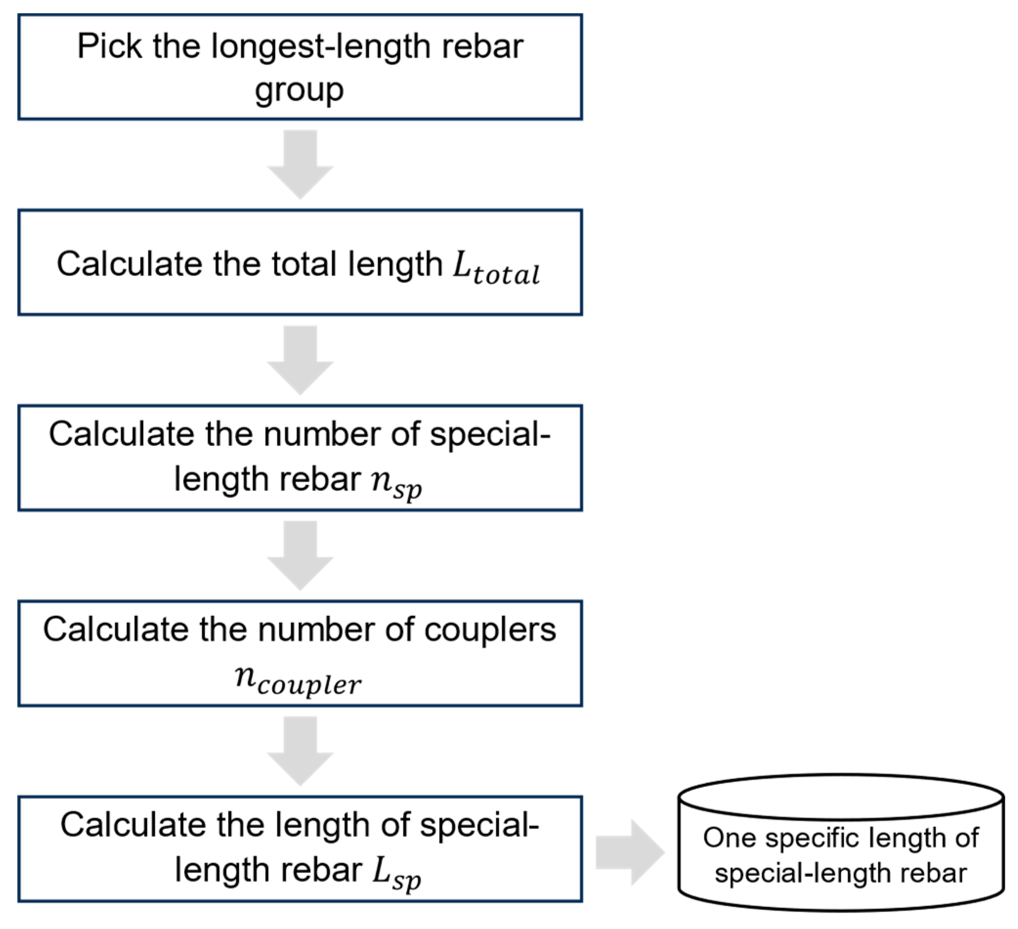
Figure 5.
Illustration of coupler’s inner gap.
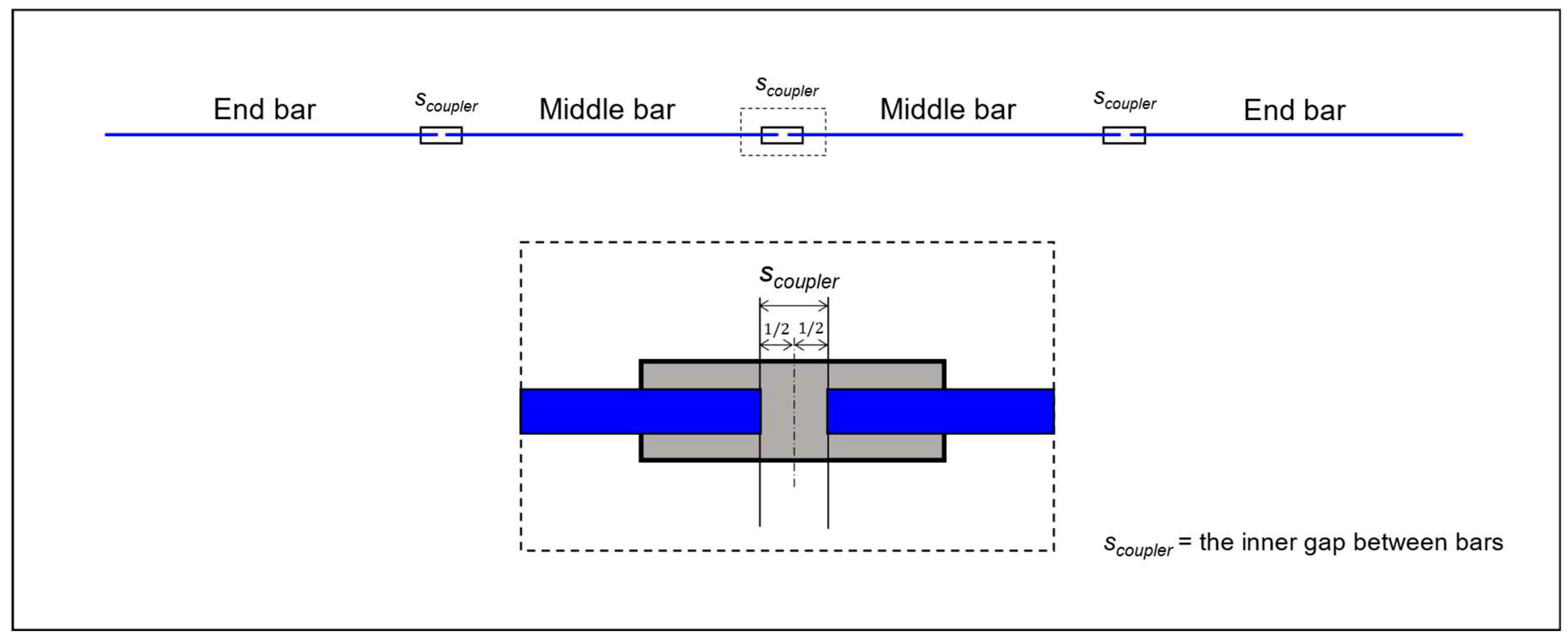
Figure 6.
Steps taken in the 3rd module of the algorithm.
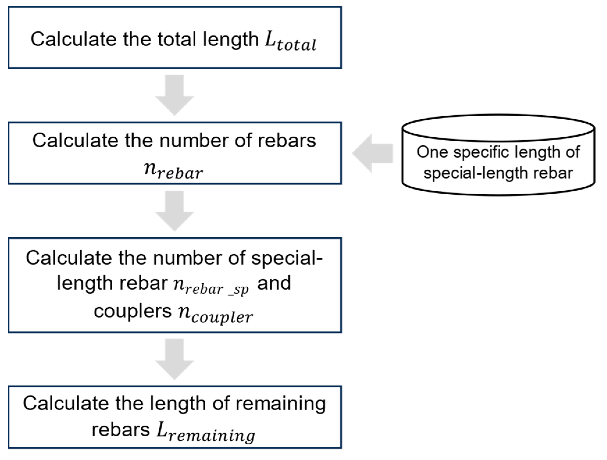
Figure 7.
Rebar groups with similar lengths (adapted from [9]).
Figure 7.
Rebar groups with similar lengths (adapted from [9]).
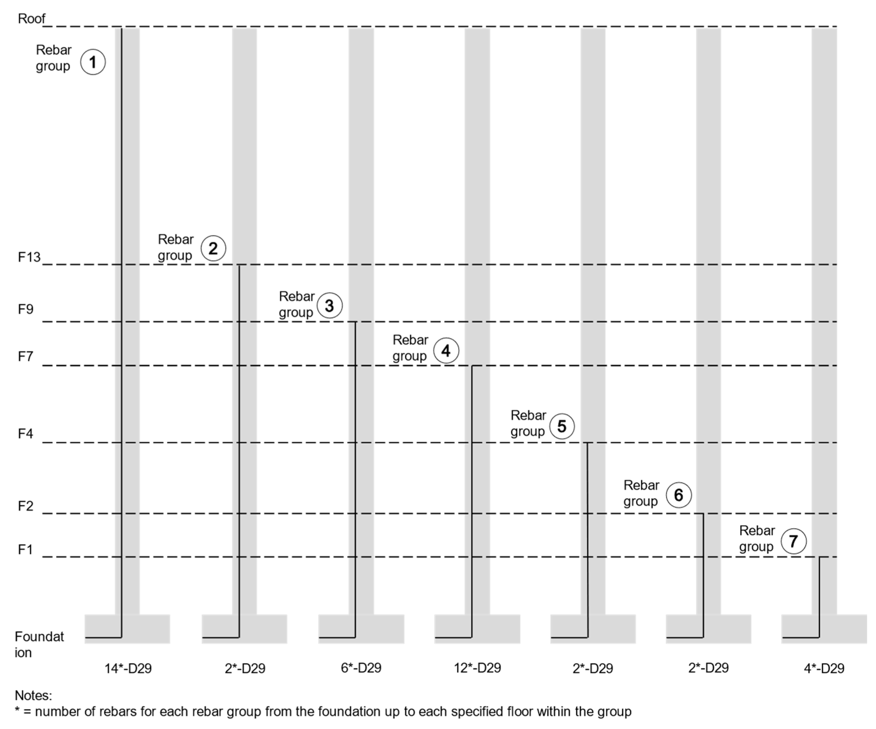
Table 1.
The impact of stock-length rebar usage on cutting waste.
| Author(s) | Structural member(s) | Rebar cutting waste |
| Khondoker [20] | RC frames | 2.69% |
| Zheng et al. [21] | RC slab | 14.49% |
| Chen and Yang [7] | RC beam section | 8.4% |
| Nadoushani et al. [8] | RC columns | 7.2% |
| RC shear walls | 10.6% |
Table 2.
The impact of special-length rebar usage on cutting waste.
| Author(s) | Structural member(s) | Rebar cutting waste |
| Porwal and Hewage [22] | RC frames | 0.93% |
| Kim et al. [23] | RC bearing wall | 0.82% |
| Lee et al. [24] | RC frames | 0.58% |
| Widjaja and Kim [25] | RC beams | 0.93% |
Table 3.
The impact of special-length rebar usage on cutting waste.
| Building code(s) | Description |
| ACI 318-19 [35] | The minimum spacing between reinforcement for column or vertical structural members should be at least 1.5db and (maximum size of coarse aggregate). |
| BS 8110-97 [36] | The minimum horizontal spacing or distance between bars should not be less than hagg + 5 mm, and vertical spacing should not be less than (maximum size of coarse aggregate). |
| JGC 15-2007 [37] | The minimum clear distance between bars for columns should not be less than 40 mm, , or 1.5db. |
Table 4.
Rebar layout and arrangement of single continuous column for each floor (adapted from [9]).
Table 4.
Rebar layout and arrangement of single continuous column for each floor (adapted from [9]).
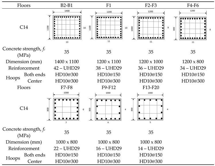 |
Table 5.
Detailed information on the column case and its reinforcement.
| Description | Content |
| Foundation depth (Df) | 600 mm |
| Foundation concrete cover (Cf) | 50 mm |
| Basement level (B2-B1) height | 8300 mm |
| Upper ground level (F1-Roof) height | 87.4 m |
| Total floor height ( | 95.7 m |
| Girder depth (Dgirder) | 700 mm |
| Rebar diameter (d) | UHD600 D29 |
| Concrete strength (fc) | B2-F20: 35 MPa |
| Girder depth (Dgirder) | 700 mm |
| Anchorage length (Lanchor) | 1050 mm |
| 90-degree hook length (Lhook) | 350 mm |
| Dowel bar length (Ldowel) | 850 mm |
| Bend deduction (Bdeduct) | 79 mm |
| D29 unit weight | 5.04 kg/m |
| Coupler inner gap (Scoupler) | 20 mm |
Table 6.
Rebar groups with similar total lengths.
| Rebar Group | Floors | No. of continuous rebars (pcs) | Total height of floor (m) |
| 1st | B2-Roof | 14 | 95.7 |
| 2nd | B2-F13 | 2 | 64.1 |
| 3rd | B2-F9 | 6 | 48.9 |
| 4th | B2-F7 | 12 | 41.3 |
| 5th | B2-F4 | 2 | 24.1 |
| 6th | B2-F2 | 2 | 12.9 |
| 7th | B2-F1 | 4 | 8.3 |
Table 7.
Remaining rebars generated through the process.
| Rebar Group | Floors | Total length (m) | Number of special-length rebars (pcs) | Remaining rebar (mm) |
| 2nd | B2-F13 | 64.87 | 6 | 70 |
| 3rd | B2-F9 | 49.67 | 4 | 6470 |
| 4th | B2-F7 | 42.07 | 3 | 9670 |
| 5th | B2-F4 | 24.87 | 2 | 3270 |
| 6th | B2-F2 | 13.67 | 1 | 2870 |
| 7th | B2-F1 | 9.07 | 0 | 9080 |
Table 8.
Special-length-priority combination with cutting patterns on the remaining rebars.
| Length (m) | Number (pcs) | Required quantity (ton) | Ordered quantity (ton) | Cutting waste (%) |
| 10.8 | 22 | 1.026 | 1.198 | 14.31 |
| 10.0 | 22 | 1.026 | 1.109 | 7.50 |
Table 9.
Quantity of continuous rebars.
| Rebar Group | Floor | No. of special lengths per one continuous rebar | Total no. of special-length rebars (pcs) | Total no. of couplers (pcs) | Required qty. (ton) | Ordered qty. (ton) | Cutting waste (ton) |
| 1st | B2-Roof | 9 | 126 | 112 | 6.8395 | 6.8584 | 0.0140 |
| 2nd | B2-F13 | 6 | 12 | 12 | 0.6513 | 0.6532 | 0.0013 |
| 3rd | B2-F9 | 4 | 24 | 24 | 1.3028 | 1.3064 | 0.0027 |
| 4th | B2-F7 | 3 | 36 | 36 | 1.9544 | 1.9596 | 0.0040 |
| 5th | B2-F4 | 2 | 4 | 4 | 0.2172 | 0.2177 | 0.0004 |
| 6th | B2-F2 | 1 | 2 | 2 | 0.1086 | 0.1089 | 0.0002 |
| 7th | B2-F1 | 0 | 0 | 0 | 0 | 0 | 0 |
| Total | 190 | 11.074 | 11.104 | 0.030 | |||
Table 10.
Overall rebar consumption and cutting waste using 10.8 m special-length rebar.
| Description | Special-length rebar (m) | Required qty. (ton) | Ordered qty. (ton) | Cutting waste (ton) | Cutting waste rate (%) |
| Continuous rebars | 10.8 | 11.074 | 11.104 | 0.030 | 0.27 |
| Remaining rebars | 10.8 | 1.026 | 1.198 | 0.172 | 14.31 |
| Total | 12.100 | 12.302 | 0.202 | 1.64 |
Table 11.
Overall rebar consumption and cutting waste using 10.8 and 10 m special-length rebars.
| Description | Special-length rebar (m) | Required qty. (ton) | Ordered qty. (ton) | Cutting waste (ton) | Cutting waste rate (%) |
| Continuous rebars | 10.8 | 11.074 | 11.104 | 0.030 | 0.27 |
| Remaining rebars | 10 | 1.026 | 1.109 | 0.083 | 7.50 |
| Total | 12.100 | 12.213 | 0.113 | 0.93 |
Table 12.
CO2 and associated costs.
| Description | Rebar quantity (ton) | CO2 emission (ton CO2-e) | Rebar cost (USD) | Coupler cost (USD) | Carbon cost (USD) | Total cost (USD) |
| A single column | 12.213 | 45.56 | 11,090 | 1562 | 3418 | 16,070 |
Table 13.
Comparison between the original design and the proposed algorithm.
| Description | Original (O) | Coupler (C) | Reduction (O-C) | Reduction rate (O-C)/O (%) |
| Required rebar quantity (ton) | 15.817 | 12.100 | 3.717 | 23.50 |
| Ordered rebar quantity (ton) | 18.164 | 12.213 | 5.951 | 32.77 |
| Cutting waste (ton) | 2.348 | 0.113 | 2.235 | 95.19 |
| CO2 emissions (ton CO2-e) | 63.67 | 45.56 | 18.11 | 28.44 |
| Rebar cost (USD) | 16,494 | 11,090 | 5404 | 32.77 |
| Splicing cost (USD) | 939 | 1562 | (623) | (66.35) |
| Carbon cost (USD) | 4775 | 3418 | 1357 | 28.42 |
| Total cost (USD) | 22,208 | 16,070 | 6138 | 27.64 |
| The cost was converted from KRW into USD using the current exchange rate [42]. | ||||
Table 14.
Comparison between the previous study’s findings and the proposed algorithm.
| Description | Previous (P) | Coupler (C) | Reduction (P-C) | Reduction rate (P-C)/P (%) |
| Required rebar quantity (ton) | 14.815 | 12.100 | 2.715 | 18.33 |
| Ordered rebar quantity (ton) | 14.939 | 12.213 | 2.726 | 18.25 |
| Cutting waste (ton) | 0.124 | 0.113 | 0.011 | 8.93 |
| CO2 emissions (ton CO2-e) | 52.36 | 45.56 | 6.80 | 12.99 |
| Rebar cost (USD) | 13,565 | 11,090 | 2475 | 18.25 |
| Splicing cost (USD) | 523 | 1562 | (1039) | (198.67) |
| Carbon cost (USD) | 3928 | 3418 | 510 | 12.99 |
| Total cost (USD) | 18,016 | 16,070 | 1946 | 10.81 |
| The cost was converted from KRW into USD using the current exchange rate [42]. | ||||
Disclaimer/Publisher’s Note: The statements, opinions and data contained in all publications are solely those of the individual author(s) and contributor(s) and not of MDPI and/or the editor(s). MDPI and/or the editor(s) disclaim responsibility for any injury to people or property resulting from any ideas, methods, instructions or products referred to in the content. |
© 2023 by the authors. Licensee MDPI, Basel, Switzerland. This article is an open access article distributed under the terms and conditions of the Creative Commons Attribution (CC BY) license (http://creativecommons.org/licenses/by/4.0/).
Copyright: This open access article is published under a Creative Commons CC BY 4.0 license, which permit the free download, distribution, and reuse, provided that the author and preprint are cited in any reuse.
Submitted:
23 December 2023
Posted:
25 December 2023
You are already at the latest version
Alerts
A peer-reviewed article of this preprint also exists.
This version is not peer-reviewed
Submitted:
23 December 2023
Posted:
25 December 2023
You are already at the latest version
Alerts
Abstract
The construction of reinforced concrete (RC) structures inevitably consumes an excessive number of rebars, leading to significant cutting waste and carbon emissions. Extensive research has been conducted to minimize this issue and its consequences; however, these methods consistently consume a substantial number of rebars. This includes a previous study that utilizes the lap splice position optimization and special-length rebar concept without considering the lapping zone regulation. Moreover, conventional lap splices pose inherent drawbacks that could jeopardize the structural integrity of RC members. In contrast, mechanical couplers eliminate the need for rebar lapping, effectively reducing rebar consumption. This research aims to evaluate the impact of an integrated mechanical coupler and special-length-priority minimization algorithm on the reduction in rebar consumption and cutting waste in RC columns, achieving near-zero cutting waste. To validate the effectiveness of the proposed algorithm, it was applied to the column rebars of an RC building. The results revealed a significant reduction in ordered rebar consumption by 18.25%, accompanied by substantial reductions in cutting waste (8.93%), carbon emissions (12.99%), and total costs (10.81%) compared with a previous study. The outcomes provide the industry with insights into further reducing rebar consumption and its related consequences. Applying the proposed algorithm to various construction projects will further amplify the corresponding benefits.
Keywords:
Subject: Engineering - Civil Engineering
1. Introduction
The construction of reinforced concrete (RC) structures inevitably consumes an excessive number of rebars and generates rebar cutting waste, with a projected range of 3-5% during the planning phase and an actual range of 5-8% during on-site realization [1]. Furthermore, the manufacture of rebars requires a tremendous amount of energy, which contributes to carbon emissions, thus posing a threat to the environment. In 2020, the global construction industry consumed 14 billion m3 of concrete [2], generating 53.9 million tons of cutting waste and emitting 188.92 million tons of CO2, resulting in a loss of USD 55.12 billion.
Conventional lap splicing with confining reinforcement, commonly used to connect adjacent rebars for decades [3,4], is one of the major contributors to waste and carbon emission issues in the industry. Lap splices necessitate longer lapping lengths, especially for larger-diameter rebars in high-rise buildings, and they have to be positioned following building codes, which augment rebar consumption and waste. Lap splice efficacy is dependent on the bonding strength between the concrete and rebars, which is reflected in the lap splice length. Moreover, investigations assert that adequate concrete cover, tensile strength, and transverse reinforcement ensure the performance of lap splices [5,6]. Building code regulations mandate specific positions or zones for lap splices, yet construction sites often find it difficult to follow these regulations and therefore disregard them [6]. Disregarding the regulation does not necessarily lead to structural failure. Although diverse optimization methods have been investigated, including cutting pattern and lap splice position optimization [7,8], their efforts have been limited to the adoption of stock-length rebars and building code regulations regarding lap splice position. As a result, it is difficult to reduce rebar cutting waste to below 5%, even with great effort.
In response to the disadvantage of stock-length rebars, researchers have introduced the use of special-length rebars to reduce cutting waste. The utilization of special-length rebars has been demonstrated to effectively minimize rebar cutting waste for beam elements, achieving waste reductions of less than 3% [9]. Despite the benefits of utilizing lap splice position flexibility and special-length rebars, column elements fabricated with this approach still exhibit substantial rebar consumption, even when zone regulations are not considered.
In addition, the application of conventional lap splicing has several drawbacks, including rebar congestion, increased rebar waste, higher costs, and impaired structural integrity [4,10,11,12,13,14,15]. The emergence of mechanical splices or couplers shed light on this issue. Couplers can connect adjacent rebars with significantly shorter lengths. They achieve greater strength than the rebar, efficiently transferring rebar tensile forces and maintaining structural integrity and stability compared to lap splices. Thus, couplers consume significantly less rebars and, eventually, less waste. It is expected that a significant reduction in rebar consumption and waste will also reduce costs and carbon emissions.
1.1. Rebar consumption and cutting waste
The global concrete volume reached 14 billion m3 in 2020 [2]. The extensive usage of concrete and rebars accounts for 65% of the CO2 emissions from the construction sector, with rebars alone responsible for 60% of this [16]. Research has established a rebar-to-concrete consumption ratio of 0.077 tons/m3 [1], indicating that the global concrete volume above corresponds to 1.078 billion tons of rebars. Considering a 5% cutting waste rate, this equates to 53.9 million tons of rebar cutting waste and 188.92 million tons of carbon emissions. Integrating these findings with a rebar price of USD 900/ton [17], a unit of rebar–carbon emissions of 3.505-ton-CO2/ton [18], and a carbon price of USD 75/ton-CO2 [19] implies a potential loss of USD 62.68 billion.
Previous research has been primarily centered on the usage of stock-length rebars to identify the most optimal rebar combination that generates the least amount of cutting waste. Nonetheless, the approach still generates a significant amount of cutting waste. Table 1 summarizes numerous studies that have attempted to optimize rebar cutting waste utilizing stock-length rebars. Additionally, investigations [7,8] also combined stock-length rebars with lap splice position optimization per the related regulation provided by building codes and failed to reduce the cutting waste to below 5%.
Faced with the challenge posed by stock-length rebars and their consequential high cutting waste, researchers and industry have actively explored alternative solutions, including special-length rebars. The use of special-length rebars enables the rebar lengths to be adjusted to fit the specific circumstances of a construction project, as they are supplied in 0.1 m increments. Previous research, as summarized in Table 2, confirms the effectiveness of special-length rebars in minimizing cutting waste, enabling the achievement of near-zero cutting waste. Nevertheless, their utilization remains limited to medium- and large-scale construction projects.
1.2. Rebar splicing methods
The need for lap joints on reinforced concrete (hereinafter, RC) structures arises due to various factors, including the limited length of the supplied rebar, variations in rebar diameter, and challenges related to transportation [13]. Although conventional lap splicing has long been considered a reliable and effective method for rebar splicing, it has several drawbacks that limit its applicability. These drawbacks include increased rebar consumption and waste, rebar congestion, a higher cost, and unsuitable use in the plastic hinge region [4,10,11,15]. Moreover, several studies [12,15,26] have highlighted that the adoption of lap splices may lead to the over-reinforcement of the section, reduced ductility, and ultimately a change in the structure’s deformation capacity. Ductility plays a vital role in averting sudden collapse due to brittle failure during seismic events [27]. Additionally, an increase in the diameter of the rebar corresponds to an extended development or anchorage length. As building codes define the lap splice length as a multiplication of factors (ranging from 1.0 to 1.3) by the development length, an extended lap splice length will ultimately increase rebar consumption and rebar waste.
Such drawbacks of conventional lap splices urge researchers and experts to devise a novel splicing method, including mechanical splices or couplers. In RC structures, a mechanical coupler serves as a device to connect two rebars, establishing a mechanical bond and eradicating the need for lap splicing. Couplers are primarily used to shorten splice length and alleviate bar congestion in connections of RC structural members [28]. Initially, related building and seismic codes prohibited the application of couplers within the plastic hinge region, especially in areas prone to high seismic activities. However, recent investigations have shown that couplers may be used in the plastic hinge region of precast concrete columns. In terms of seismic application, the coupler length should be less than 15db [29]. This discovery provides valuable knowledge regarding the behavior and applicability of couplers in RC structures. Furthermore, previous studies have reported several benefits of mechanical couplers [4,11,15]: (1) alleviating rebar congestion problems; (2) significantly reducing rebar waste and consumption; (3) allowing for the effective control of concrete crack propagation; (4) improving the structural continuity between rebars, ensuring better integrity; (5) reducing the required labor, resulting in construction cost reduction; and (6) providing feasibility to connect rebars of varying lengths and diameters.
A variety of couplers are commercially accessible and available on the market, namely, (1) shear screw couplers [28,29], (2) grouted sleeve couplers [28,29], (3) parallel threaded couplers [4,28,29], (4) swaged couplers [4,28,29], and (5) rib-thread couplers [4,28,29], as illustrated in Figure 1. Threaded couplers are the most prevalent type of coupler, characterized by their short length and ease of installation [14,30]. Threaded couplers can be categorized as parallel threaded couplers (PTCs), taper threaded couplers (TTCs), upset-headed couplers (UHCs), and rib-thread couplers (RTCs) [31].
1.3. Research feasibility and research objective
Mechanical couplers have not been prevalently used due to three challenges: pre-planning requirements, cost and installation time concerns, and constructability issues if rebar prefabrication and assembly are not well organized. BIM-based integrated project delivery can mitigate the challenges of pre-planning and constructability. Progress in technology combined with a concurrent rise in material and labor costs have positioned couplers as competitive substitutes for lap splices, notably for rebar diameters exceeding 19 mm.
Conventional lap splices have inherent disadvantages related to rebar consumption, waste, and structural integrity. Conversely, couplers offer many advantages as potential substitutes for splicing, as described above. Hence, this research aims to evaluate the impact of an integrated mechanical coupler and a special-length-priority minimization algorithm on the reduction in rebar consumption and cutting waste in RC columns, achieving near-zero cutting waste. This research restricts the proposed algorithm to the main rebars of the columns. To the best of the authors’ knowledge, the combined use of mechanical couplers, special-length rebars, and flexible coupler placement to minimize rebar consumption and waste has received little attention. In contrast, the crucial role of each structural member’s characteristics in optimizing the algorithm process has been largely overlooked.
The effectiveness of the proposed approach is assessed by undertaking the following steps: (1) the establishment of the proposed algorithm; (2) validation through a case study; (3) the calculation of cutting waste, rebar consumption, carbon emissions, and associated costs and a comprehensive comparison with the original design and conventional lap splice method; and (4) an in-depth analysis and discussion of the obtained results. With the present limited attention toward rebar consumption optimization, this initiative carries significant importance for both researchers and the construction industry, delving into this critical concern. In addition, this research also provides insights into the possibility of reducing the number of required rebars without compromising the structural integrity of RC structures.
2. Column Characteristics
Columns, vertical load-bearing components responsible for carrying axial compressive loads [32], transfer the entire load from the beams and slabs above to the foundation while ensuring the stability of the structure. They are designed to withstand axial loads, with bending loads playing a relatively minor role. However, columns can also experience bending, torsion, and shear forces, particularly when subjected to eccentric or lateral loads. Excessive transverse loads can induce buckling, resulting in sudden bending deformations and buckling failure. Column longitudinal reinforcement resists axial and bending loads; torsional reinforcement resists torsion; and transverse reinforcement resists shear forces and buckling, as well as enhancing lateral load resistance by providing confinement. Moreover, the shear stress in a column may not be uniformly distributed, with the maximum shear stress occurring at the end of the column. These loads can significantly affect the structural integrity of the building, increasing the risk of failure. Nonetheless, this research mainly centers its attention on the main rebars within the columns. Figure 2 illustrates the detailed column rebar arrangement considering couplers.
Continuous columns are reinforced with dowel bars that connect the foundations and columns, longitudinal rebars that are repeatedly connected by couplers on each floor, and rebars that are anchored to the top beam of the building [33]. High-rise buildings are generally reinforced with 20 mm rebars, while skyscrapers require 32 mm or larger rebars [34].
The use of couplers offers the advantage of reducing bar congestion issues, which requires careful attention to rebar spacing. Rebar spacing must be maintained, as certain types of couplers can affect the minimum spacing requirements and reduce the bond between the concrete, rebar, and coupler, decreasing strength and quality. Building codes define the minimum rebar spacing requirements, and they are summarized in Table 3.
3. Methodology
The proposed framework for evaluating the impact of integrated mechanical couplers and the special-length-priority minimization algorithm on the reduction in column rebar consumption and cutting waste while maintaining a near-zero waste strategy is divided into five modules, as depicted in Figure 3: (1) model preparation and data collection; (2) the application of integrated mechanical couplers and special-length-priority minimization algorithm on main rebars of the column; (3) rebar adjustment considering the identified special-length rebars; (4) special-length-priority minimization for the remaining rebars and quantity confirmation; and (5) the validation of the algorithm in terms of the rebar consumption, rebar cutting waste, CO2 emissions, and associated cost. In this research, the minimum order quantity for special-length rebars is defined as 50 tons and two months of preorder time [24].
3.1. Module 1: Model preparation and data collection
In this module, the column is initially built as a structural BIM model in Autodesk Revit 2022 based on the structural analysis and design results. A 3D model of concrete columns from the foundation to the roof floor is built using their length, width, and depth. Reinforcements and their details are then added to the model in accordance with the relevant building codes, such as the rebar shape code [38] and other building codes. British Standard 8666 [38] governs the requirements for the rebars’ dimensioning, scheduling, cutting, and bending, allowing for an exact calculation. The 3D model shows that the column has various rebar layout arrangements from the basement floor to the roof floor, as the column dimensions and the number of rebars decrease on the upper floors. It can be perceived that certain rebars stretch from the foundation to the roof, while others may extend only up to a specific point within the column. Therefore, rebars with similar lengths are grouped into the same group.
3.2. Module 2: The application of integrated mechanical couplers and special-length-priority minimization algorithm on main rebars of the column
The previous module identifies the longest rebar group. In this module, a set of mathematical equations is applied to identify one specific special-length rebar, accommodating the usage of couplers. Rebar details regarding the floors (Hfloor), the number of rebars, and the lengths of the hook anchorage (Lanchorage+hook) of the original design must be obtained. Figure 4 describes the steps taken in this module. These steps [9] are developed under the premise that the minimum spacing between the bars meets the regulation.
First, the total length (Ltotal) of the continuous rebar in the longest rebar group is calculated. The total length equation of the column’s main rebar that extends from the foundation to the top girder is expressed in Equation (1). Equation 1 considers the following factors: the height of each floor, the total number of floors, the depth of the girder, the length of the dowel and anchorage, and the bending deduction.
Here, Ltotal is the total length of the continuous main rebar (mm), Hfloor is the height of the floor (mm), nfloor is the number of floors, Dgirder is the depth of the girder (mm), Ldowel is the length of the dowel bar (mm), Lanchor+hook is the hook anchorage length (mm), and Bdeduct is the bending deduction.
Second, the number of special-length rebars (nsp) is calculated by dividing the total length of the rebars by the reference length or the maximum length of the rebars that can be ordered (Lref). The ceiling function is used to round the result up to the nearest integer, as expressed in Equation 2:
Third, the number of couplers required to connect the rebars (ncoupler) in the group can be calculated using Equation 3, deducting one from the number of special-length rebars (nsp):
Finally, the total length of the special-length rebars is divided by the number of special-length rebars to obtain the calculated length (Lcalc), as shown in Equations 4 and 5. A coupler may include an inner gap (scoupler) between the rebars to facilitate installation in the case of misaligned threads and for grouting purposes. The inner gap of the coupler may vary depending on the type and diameter of the coupler itself. Thus, this gap has to be deducted from the rebars. Half of the gap is deducted from the end bar, whereas the entire gap is deducted from the middle bar, as illustrated in Figure 5. The round-up function is used, as special-length rebars (Lsp) can only be ordered in 0.1m increments, as shown in Equation 6.
3.3. Module 3: Rebar adjustment considering the identified special-length rebars
This module attempts to accommodate other rebar groups by utilizing the special-length rebars identified in the previous module. Dividing the total length of each rebar group by the identified special length of the rebars may result in a non-integer value, which results in remaining rebars. The steps [9] taken in this module are illustrated in Figure 6.
First, the total rebar length for each rebar group (Ltotal) can be calculated using Equation 1 described above. Second, prioritizing the special length obtained, the number of rebars within the rebar group (nrebar) can be calculated by dividing the total length (Ltotal) with the identified special length of the rebars (Lsp) in the previous module, as expressed in Equation 7. In this equation, the ceiling function is used to generate an integer number. Third, equation 8 is utilized to identify the number of special-length rebars (nrebar_sp) for each rebar group. Then, the number of couplers required in each rebar group (ncoupler) can be calculated utilizing Equation 9.
Nevertheless, not all rebars can be accommodated by the identified special length of the rebars, resulting in remaining rebars. The remaining rebar length (Lremaining) can be calculated by subtracting the total length of the special-length rebars that can be installed within the rebar group and coupler’s inner gap from the total rebar length (Ltotal), as shown in Equation 10. The number of remaining rebars should always be one.
3.4. Module 4: Special-length-priority minimization with cutting patterns for the remaining rebars and quantity confirmation
This module is divided into two processes, special-length-priority minimization for remaining rebars and rebar quantity confirmation for both continuous and remaining rebars. The number of special-length rebars is identified utilizing Equations 11 to 16, as proposed by previous investigations [9,24]. Equation 11 plays a role as an objective function, searching for the special-length rebar that generates the lowest ratio of cutting waste.
Here, Lspi is the special length I (mm), li is the length of the cutting pattern i derived by combining multiple demand lengths (mm), and ni is the number of rebar combinations with the same cutting pattern.
Equations 12 to 16 play a role as the constraints needed to achieve the objective of minimization. Equation 12 ensures that the total length of cutting pattern i (li) is less than or equal to the special length (Lspi). Equation 13 ensures that the number of combinations with the same cutting pattern i (ni) is greater than zero. Equation 14 requires that the special length (Lspi) is within the range of the minimum (Lmin) and maximum (Lmax) lengths of the special-length rebar that can be ordered. Equation 15 ensures that the total quantity of rebars (Qtotal) is greater than or equal to the minimum order quantity required by steel mills (Qso). Equation 16 establishes that the rebar cutting waste () should be equal to or less than the target rebar cutting waste ().
The rebar cutting waste (RCW), required quantity (Qreq), and ordered quantity (Qord) can be obtained at the end of this module, using a set of equations described in previous research [9]. Equation 17 can be used to calculate the rebar cutting waste, which is defined as the difference between the required and ordered quantities divided by the ordered quantity. The required and ordered quantities are the total quantity of rebars required and used on the construction site and the total quantity of rebars ordered from steel mills, respectively. Calculating the required quantity of continuous rebars (Qreq−c) involves utilizing the rebar length calculated using Equations 4-5, as illustrated in Equation 18. For the remaining rebars, their quantity (Qreq−r) can be determined by considering the total length of cutting pattern i (), outlined in Equation 19. To calculate the ordered quantity (Qord) for both the continuous and remaining rebars, considering the identified special-length rebar, Equation 20 can be utilized.
3.5. Module 5: Validation of the proposed algorithm
In this module, the results from the previous modules (required quantity, ordered quantity, and rebar cutting waste) are compiled and compared with the original design and a previous study’s finding using conventional lap splices. The required quantity, ordered quantity, and cutting waste are converted into CO2 emissions and associated costs. This module quantifies the impact of utilizing couplers on rebar consumption, rebar cutting waste, CO2 emissions, and total costs.
4. Case study and validation of the algorithm
4.1. Case study application
A single continuous column that extends from the building’s foundation to the roof floor was chosen for the application of the proposed algorithm. The building comprised 22 floors, that is, 20 floors above ground and 2 basement floors. The column height varied from 3.7 m to 6 m depending on the floor height. For this case, the minimum order quantity of 50 tons was temporarily disregarded to identify the optimal solution.
Regarding the coupler, a rib-thread coupler from Tokyo Tekko Co. Ltd. [39] was selected for this research due to its wide range of diameters; ease of installation; high strength; and ability to resist lateral forces, such as wind and earthquakes. See Appendix A (Figure A1 and Table A1) for the detailed specifications of the coupler. Additionally, this research utilized threaded rebars from the same manufacturer. Table 4 depicts the rebar layout and arrangement of the column. Detailed information on the column and its reinforcement can be seen in Table 5.
The BIM model revealed that some of the main rebars spanned the entire column height from the foundation to the roof, while others extended to specific points within the column, as illustrated in Figure 7. These main rebars were grouped into seven groups, as presented in Table 6.
4.1.1. The application of integrated mechanical couplers and special-length-priority minimization algorithm on main rebars of the column
This stage determined the specific special length of the continuous rebars accommodating the use of couplers. Column and reinforcement information was collected, including the rebar layout and arrangement. The 1st rebar group, which spanned the entire column, was initially used to determine the special length rebars. Utilizing Equation 1, a total rebar length of 97.09 m was obtained.
Then, the number of special-length rebars was identified using Equation 2, given a maximum stock length that steel mills can provide of 12 m. This maximum stock length may vary depending on the country. The calculation identified that nine special-length rebars were required, which means that there were nine continuous special-length rebars connected with eight couplers (Equation 3).
Next, the special length of the rebars was calculated utilizing Equations 4-6. A minimum of a 20 mm gap is required between the inner threads for coupler sizes above D16; thus, for the end bar, 10 mm was subtracted from the exact special length, resulting in 10.778 m, and, for the middle bar, 20 mm was subtracted from the special length, resulting in 10.768 m. Due to the characteristics of special-length rebars, this was rounded up to 10.8 m. Therefore, nine special-length rebars of 10.8 m were connected with eight couplers for the column’s one continuous rebar system that extended from the foundation to the roof of the building.
4.1.2. Rebar adjustment considering the identified special length rebar
The special length rebar identified in the previous module was then utilized for other rebar groups. Consequently, one remaining rebar for each rebar group was generated, since the division of the total length of each group by the special length did not result in an integer value. The 2nd rebar group, which spanned from the foundation to the 13th floor, was used as an example for this process.
The total rebar length for the 2nd rebar group was calculated utilizing Equation 1, and 64.87 m was obtained. Then, the number of rebars within the 2nd rebar group was calculated using Equation 7, resulting in seven rebars that were embedded from the foundation to the 13th floor. This means that six of the seven rebars were installed with a special length of 10.8 m, generating one remaining rebar. These rebars were connected using six couplers (Equation 9). Equation 10 was utilized to calculate the length of the remaining rebar by subtracting the total length of the special-length rebar required from the total rebar length, resulting in a length of 70 mm (0.07 m). This process was repeated for the rest of the rebar groups, and it is summarized in Table 7
4.1.3. Special-length-priority minimization and quantity confirmation
The remaining rebars obtained were then combined using the special-length-priority minimization algorithm to identify the most optimum special-length rebar that produces the least amount of waste, as summarized in Table 8. Utilizing Equations 11-16, two special-length rebars were obtained: 10.8 m and 10 m. The 10.8 m special-length rebar could maintain one specific length for the entire column. A rebar maintaining one specific length for an entire column is preferable for steel mills. Once the special lengths of the rebars were identified, the required and ordered quantities could be calculated. The ordered quantity was determined by multiplying the length by the total number of special-length rebars and the rebars’ unit weight. The required quantity of remaining rebars was determined by the length of each combined rebar, the number of rebars that were to be combined, and the unit weight of the rebars. Nevertheless, a cutting waste of 14.31% was generated, while the 10 m special-length rebar generated 7.50% cutting waste. For reference, since special-length rebars are provided by the steel mills in 0.1 m increments, a stock length of 10 m can be categorized as a special-length rebar. Thus, a 10 m special-length rebar can be used instead of a 10.8 m rebar.
The total number of special-length rebars was obtained by multiplying the number of special lengths within a continuous rebar system by the number of rebars in each rebar group. The unit weight of D29 rebars can vary between manufacturers; however, in this case, 5.04 kg/m was used [40]. The required quantity was calculated using the special length before the ceiling function was applied, while the ordered quantity was calculated using the rounded-up length, as shown in Equations 18-20. Table 9 provides a summary of the confirmed rebar quantities.
4.2. Validation of the algorithm
4.2.1. Rebar consumption and rebar cutting waste
After all the required and ordered quantities were obtained, rebar consumption and rebar cutting waste could be assessed. Equation 17 was utilized to calculate the overall rebar cutting waste. Using a 10.8 m special-length rebar, the continuous rebars had a required quantity of 11.074 tons and an ordered quantity of 11.104 tons, with a 0.27% cutting waste. The same length was also used to combine the remaining rebars, resulting in a required quantity of 1.026 tons and an ordered quantity of 1.198 tons, with a 14.31% cutting waste. Table 10 summarizes the overall quantities and cutting waste generated by the 10.8 m special-length rebar. As shown in the table, using one specific special length of 10.8 m resulted in a required quantity of 12.100 tons; an ordered quantity of 12.302 tons; and a cutting waste of 1.64%, which exceeds 1%. Using only the 10.8 m special-length rebar resulted in a rebar consumption of 12.302 tons for the construction of the column.
However, using the 10 m special-length rebars to combine the remaining rebars generated a required quantity of 1.026 tons and an ordered quantity of 1.109 tons, with a 7.50% cutting waste. Utilizing the 10.8 m special-length rebar for continuous rebars and the 10 m special-length rebar for the remaining rebars generated a required quantity of 12.100 tons and an ordered quantity of 12.213 tons, with a 0.93% cutting waste, as shown in Table 11. The use of the 10.8 m and 10 m special-length rebars resulted in a rebar consumption of 12.123 tons for the construction of the column. As previously mentioned, a stock-length rebar of 10 m can be regarded as a special-length rebar; thus, the use of the 10.8 and 10 m special-length rebars was preferable. Originally, one specific special length was preferable as long as a cutting waste of less than or equal to 1% was maintained.
4.2.2. CO2 emissions and cost reduction analysis
An investigation conducted by Ghayeb et al. [18] found that rebars generate 3.505-ton CO2-e/ton. The CO2 emission unit rate of the D29 coupler was interpolated from their findings, resulting in 14.50-kg CO2-e/pcs (See Appendix B, Table A2). Based on this information, the ordered quantities of the rebars and couplers could be converted into the total CO2 emissions.
The total cost encompasses the rebar material cost, the splicing cost encompassing both processing and material costs, and carbon pricing. The total CO2 emissions were multiplied by the carbon price of USD 75/ton-CO2, as defined by the IMF [19]. To reflect the current market conditions, the rebar cost was calculated based on the available rebar price [17] and inflation rate [41], resulting in a value of USD 908 per ton. The installation expense associated with each lap splice or coupler, termed the processing cost, was considered identical for both methods. This cost was determined to reflect the current inflation rate [41], employing data from the study conducted by Kwon et al. [1]. The material costs and processing costs of lap splices and couplers can be seen in Appendix B (Table A3). The total CO2 emissions and associated costs are tabulated in Table 12. As shown in Table 8, 12.213 tons of rebars was consumed, 45.56 tons of CO2-e was generated, and USD 16,070 was required to construct a single column.
4.2.3. Comparison of the obtained results
To validate and evaluate the impact of the proposed algorithm, the rebar quantity and its performance were evaluated by comparing the rebar quantity, cutting waste, CO2 emissions, and total cost of the original design and a previous study’s findings [9] to the results generated by the proposed algorithm. The original design quantity was calculated based on 6 m and 8 m stock-length rebars and conventional lap splices (see Appendix Table A4). The original design had a total required and ordered rebar quantity of 15.817 tons and 18.164 tons, respectively, with 2.348 tons (12.93%) of cutting waste. Conversely, the proposed algorithm generated a required rebar quantity of 12.100 tons and an ordered rebar quantity of 12.213 tons, with 0.113 tons (0.93%) of cutting waste. Table 13 provides a detailed summary of the comparison between the original design and the proposed algorithm.
The proposed algorithm surpassed the original design in terms of resource efficiency and waste generation, as shown in the table above. The splicing cost for the original design was based on 474 pcs of lap splices, while the proposed algorithm was based on 190 pcs of couplers. As shown in the table, there was a substantial reduction in the ordered rebar consumption by 32.77%, leading to significant decreases in cutting waste (95.19%), CO2 emissions (28.44%), and total cost (27.64%).
Compared to a previous study’s findings [9], the proposed algorithm achieved superior outcomes by generating a lower quantity of rebar and cutting waste, as detailed in Table 14. Notable reductions of 18.25% (2.726 tons) in the ordered rebar and 8.93% (0.011 tons) in cutting waste were achieved, leading to a 10.81% decrease in total cost despite the lap splice cost being significantly lower than the coupler’s cost. These results confirm that the application of couplers effectively reduced rebar consumption.
5. Discussion
Conventional lap splicing is the most common method for rebar connection due to its simplicity and low cost. However, it has several drawbacks:
- It requires adherence to the lapping zone as recommended by building codes, which can limit flexibility and lead to more rebar waste.
- It is vulnerable to errors, such as an inappropriate lapping length or erroneous installation, which can jeopardize its performance.
- It requires more and longer rebars as the diameter increases, making it impractical for large-diameter rebars. The American Concrete Institute (ACI) [36] specifically prohibits the use of lap splices for rebar joints larger than 36 mm in diameter.
- It is difficult to inspect and repair.
Therefore, there is a need for alternative rebar connection methods that address these drawbacks.
The welded joint technique serves as an alternative option to conventional lap splicing, reducing rebar consumption but requiring higher expenses and skilled labor. However, this method emits flames and smoke, likely endangering nearby construction activities, and the welding gas used is not entirely environmentally friendly. Furthermore, inadequately executed welded joints may be prone to cracking.
Mechanical couplers are a fast and easy way to connect rebars, saving time and costs, as well as reducing rebar usage and cutting waste. Their increasing popularity is driven by decreasing costs and rebar shortages. This study demonstrated that mechanical couplers could reduce the ordered rebar usage by 32.77% and cutting waste by 95.19% for column structures. Compared to previous findings [9], a significant 18.25% reduction in rebar consumption was observed, validating the coupler’s effectiveness. Coupler selection can impact cutting waste due to the coupler’s inner gap. However, coupler selection is challenging due to the wide variety available, including non-seismic and seismic options. Additionally, coupler usage is primarily limited to new construction. Further research is warranted to optimize coupler selection and utilization in seismic regions and retrofitting applications.
The ease of the installation of couplers enhances construction site productivity. To preserve and boost this productivity, it is essential to have systematic planning and supply chain management (SCM) strategies for couplers throughout the construction process. Future research could focus on the development of an SCM model that prioritizes couplers, including coupler selection, prefabricated rebar processes, and supporting devices.
Nonetheless, the integration of couplers and special-length rebars into a wide range of construction projects, including buildings and other large infrastructure projects, represents a significant opportunity to reduce rebar consumption. This not only lowers construction costs but also accelerates the construction process and mitigates the environmental impacts associated with rebar use.
6. Conclusions
This research evaluated the impact of integrated mechanical couplers and a special-length-priority minimization algorithm on rebar consumption and cutting waste reduction by proposing a novel framework that considers the use of special-length rebars. A single column was used as a case study to demonstrate the proposed algorithm’s effectiveness. Its impact was evaluated by comparing its results to those of conventional lap splicing. The following key findings were identified:
- There was a substantial reduction in the ordered rebar consumption with the proposed algorithm consuming 5.951 tons less rebar (32.77%) compared to the original design that employs conventional lap splicing. A reduction of 2.726 tons (18.25%) was also observed when compared to a previous study’s findings.
- The proposed algorithm reduced cutting waste by 95.19% compared to the original design; a cutting waste rate of 0.93% was obtained, representing the achievement of near-zero cutting waste. In addition, using a single length of special-length rebar for both continuous and remaining rebars appeared to reduce cutting waste less significantly.
- The proposed algorithm reduced carbon emissions by 18.11 tons eCO2 (28.44%) and total costs by USD 6138 (27.64%). Compared to a previous study’s finding, a reduction of 6.8 tons of eCO2 (12.99%) and USD 1946 (10.81%) was observed for both CO2 emissions and total costs, respectively. This showcases the potential of integrated couplers and the special-length-priority minimization algorithm in significantly reducing rebar consumption and waste, as well as CO2 emissions and total costs, without harming the members’ structural integrity.
- It should be noted that couplers are generally used in new construction, with some exceptions in retrofitting or renovation projects. The cost of couplers is expected to decrease as their usage becomes more prevalent.
Upcoming research should investigate the feasibility of developing systematic planning and supply chain management (SCM) strategies that consider coupler usage, in addition to coupler selection and supporting devices. As couplers offer speed and ease of installation, construction site productivity should be maintained throughout all phases. This research demonstrates the significant impact of an integrated coupler and the special-length-priority algorithm on rebar consumption and cutting waste, providing the industry with insights into further reducing rebar and related consequences. Applying the proposed algorithm to various construction projects will further amplify the corresponding benefits.
Author Contributions
Conceptualization, D.J.K. and S.K.; methodology, D.D.W. and S.K.; validation, D.J.K. and S.K.; formal analysis, D.D.W.; investigation, D.D.W.; resources, D.J.K. and S.K.; data curation, D.J.K. and S.K.; writing—original draft preparation, D.D.W.; writing—review and editing, D.D.W., D.J.K. and S.K.; supervision, D.J.K. and S.K.; project administration, D.J.K.; funding acquisition, S.K. All authors have read and agreed to the published version of the manuscript.
Funding
This research was supported by the National Research Foundation of Korea (NRF) grants funded by the government of the Republic of Korea (MOE) [No. 2022R1A2C2005276].
Data Availability Statement
Data sharing is not applicable to this article.
Conflicts of Interest
The authors declare no conflicts of interest.
Appendix A
Figure A1.
Details of a rib thread coupler [40].
Figure A1.
Details of a rib thread coupler [40].
Table A1.
Specifications of the rib thread coupler available (in mm) [40].
Table A1.
Specifications of the rib thread coupler available (in mm) [40].
| Bar Size | Outside diameter of the coupler | Length | Dimension of thread | |||||
| Coupler | Nut | Total | Pitch | Inside diameter | Root diameter | |||
| B | C | L1 | L2 | L | P | Di | Do | |
| 19 | 29 | 30 | 100 | 20 | 140 | 8 | 18.9 | 22.3 |
| 22 | 34 | 35 | 110 | 20 | 150 | 9 | 21.8 | 25.6 |
| 25 | 38 | 39 | 120 | 20 | 160 | 10 | 24.8 | 29.0 |
| 29 | 43 | 44 | 135 | 20 | 175 | 12 | 28.2 | 33.0 |
| 32 | 48 | 49 | 160 | 20 | 200 | 13 | 31.4 | 36.6 |
Appendix B
Table A2.
Carbon emissions unit of couplers [19].
Table A2.
Carbon emissions unit of couplers [19].
| Diameter | CO2 emissions (kg-CO2-e/pcs) |
| 12 | 1.91 |
| 16 | 3.33 |
| 20 | 4.69 |
| 25 | 8.60 |
| 29 | 14.49 |
| 32 | 23.98 |
| The data for D29 was interpolated using regression. | |
Table A3.
Material and processing costs of rebars and couplers.
| Description | Material cost | Processing cost | ||
| Rebar (USD/ton) | Coupler (USD/pcs) | Lap splice (USD/m) | Coupler (USD/m) | |
| D40 | 908 | 12.35 | 2.09 | 2.09 |
| D35 | 908 | 11.50 | 1.75 | 1.75 |
| D32 | 908 | 8.44 | 1.62 | 1.62 |
| D29 | 908 | 6.90 | 1.32 | 1.32 |
| D25 | 908 | 6.14 | 1.05 | 1.05 |
| D22 | 908 | 5.37 | 0.80 | 0.80 |
| D19 | 908 | 4.22 | 0.59 | 0.59 |
| The data of D40 was interpolated using regression. The processing cost for lap splice should be multiplied by the lapping length mandated. The cost was converted from KRW into USD using the current exchange rate [42]. | ||||
References
- Kwon, K.; Kim, D.; and Kim, S. Cutting waste minimization of rebar for sustainable structural work: A systematic literature review. Sustainability 2021, 13, 5929. [Google Scholar] [CrossRef]
- Global Cement and Concrete Association. Cement and Concrete around the World. 2023. Available online: https://gccassociation.org/concretefuture/cement-concrete-around-the-world/ (accessed on 23 November 2023).
- Swami, P.S.; Javheri, S.B.; Mittapalli, D.L.; Kore, P.N. Use of Mechanical Splices for Reinforcing Steel. In Proceedings of the National Conference on Innovative Trends in Engineering and Technology, Solapur, Maharashtra, India, 11–12 March 2016; pp. 1–6. Available online: https://www.neliti.com/publications/426567/use-of-mechanical-splices-for-reinforcing-steel#cite (accessed on 23 November 2023).
- Chiari, V. G.; Moreno, J. A. L. Experimental evaluation of coupler behavior for mechanical rebar splices in reinforced concrete structures. IBRACON Structures and Materials Journal 2018, 11, 1326–1353. [Google Scholar] [CrossRef]
- Almedia, J.P.; Prodan, O.; Tarquini, D.; Beyer, K. Influence of Lap Splices on the Deformation Capacity of RC Walls. I: Database Assembly, Recent Experimental Data, and Findings for Model Development. J. Struct. Eng. 2017, 143, 04017156. [Google Scholar] [CrossRef]
- Widjaja, D.D.; Rachmawati, T.S.N.; Kwon, K.; Kim, S. Investigating Structural Stability and Constructability of Buildings Relative to the Lap Splice Position of Reinforcing Bars. J. Korea Inst. Build. Constr. 2023, 23, 315–326. [Google Scholar] [CrossRef]
- Nadoushani, Z.S.M.; Hammad, A.W.; Xiao, J.; Akbarnezhad, A. Minimizing Cutting Wastes of Reinforcing Steel Bars Through Optimizing Lap Splicing within Reinforced Concrete Elements. Constr. Build. Mater. 2018, 185, 600–608. [Google Scholar] [CrossRef]
- Chen, Y.H.; Yang, T.K. Lapping Pattern, Stock Length, and Shop Drawing of Beam Reinforcements of an RC Building. J. Comput. Civ. Eng. 2015, 29, 04014028. [Google Scholar] [CrossRef]
- Widjaja, D.D.; Rachmawati, T.S.N.; Kim, S.; Lee, S. An Algorithm to Minimize Near-zero Rebar Cutting Waste and Rebar Usage of Column. Sustainability 2024, 16, 308. [Google Scholar] [CrossRef]
- Damsara, K.D.P.; Kulathunga, D.D.T.K. Analysis on Effectiveness of Rebar Couplers in Splicing of Reinforcement Bars. In Proceedings of the International Symposium on Advances in Civil and Environmental Engineering Practices for Sustainable Development (ACEPS-2018), Galle, Sri Lanka, 15 March 2018; Available online: https://www.researchgate.net/publication/325818277_Analysis_on_Effectiveness_of_Rebar_Couplers_in_Splicing_of_Reinforcement_Bars.
- Singh, R.; Himanshu, S. K.; Bhalla, N. Reinforcement Couplers As An Alternative To Lap Splices: A Case Study. International Journal of Engineering Research & Technology 2013, 2, 1–6. [Google Scholar] [CrossRef]
- Nateghi-Alahi, F.; Shokrzadeh, M. R. Behavior considerations for mechanical rebar couplers. In Proceedings of the University of Tokyo International Congress on Science and Engineering, Tokyo, Japan, 14–15 October 2019; pp. 30–41. [Google Scholar]
- Dabiri, H.; Kheyroddin, A.; Dall’Asta, A. Splice Methods Used for Reinforcement Steel Bars: A State-of-the-Art Review. Constr. Build. Mater. 2022, 320, 126198. [Google Scholar] [CrossRef]
- Moka, V. T. K.; Rajendran, S. C. Role of coupler in structural behavior of RC elements. Materials Today: Proceedings 2022, 64, 1035–1042. [Google Scholar] [CrossRef]
- Shokrzadeh, M. R.; Nateghi, A. F.; Mansoori, M. R.; Pasha, P. Failure area evaluation of the coupler with threaded bar: Experimental and Numerical study. International Journal of Advanced Structural Engineering 2022, 12, 531–543. [Google Scholar] [CrossRef]
- Kim, K.; Jeon, Y.; Park, Y.J.; Park, S. Sustainable Anti-Tank Obstacle System Applying Civil-Military Cooperation in Highly Urbanized Areas. Sustainability 2022, 14, 12715. [Google Scholar] [CrossRef]
- Construction Association of Korea. Construction on Hold as Material Prices Go through the Roof. 2022. Available online: https://koreajoongangdaily.joins.com/2022/04/22/business/industry/Inflation/20220422165447730.html (accessed on 23 November 2023).
- Ghayeb, H. H.; Razak, H. A.; Sulong, N. H. R. Evaluation of the CO2 emissions of an innovative composite precast concrete structure building frame. Journal of Cleaner Production 2020, 242, 118567. [Google Scholar] [CrossRef]
- IMF. Why countries must cooperate on carbon prices. 2023. Available online: https://www.imf.org/en/Blogs/Articles/2022/05/19/blog-why-countries-must-cooperate-on-carbon-prices (accessed on 23 November 2023).
- Khondoker, M.T.H. Automated reinforcement trim waste in RC frame structures using building information modeling and mixed integer linear programming. Automation in Construction 2021, 124, 103599. [Google Scholar] [CrossRef]
- Zheng, C.; Yi, C.; Lu, M. Integrated optimization of rebar detailing design and installation planning for waste reduction and productivity improvement. Automation in Construction 2019, 101, 32–47. [Google Scholar] [CrossRef]
- Porwal, A.; Hewage, K. N. Building information modeling-based analysis to minimize the waste rate of structural reinforcement. Journal of Construction Engineering and Management 2012, 138, 943–954. [Google Scholar] [CrossRef]
- Kim, S.K.; Hong, W.K.; Joo, J.K. Algorithms for Reducing the Waste Rate of Reinforcement Bars. J. Asian Archit. Build. Eng. 2004, 3, 17–23. [Google Scholar] [CrossRef]
- Lee, D.; Son, S.; Kim, D.; Kim, S. Special-Length-Priority Algorithm to Minimize Reinforcing Bar-Cutting Waste for Sustainable Construction. Sustainability 2020, 12, 5950. [Google Scholar] [CrossRef]
- Widjaja, D.D; Kim, S. Reducing Rebar Cutting Waste and Rebar Usage of Beams: A Two-Stage Optimization Algorithm. Buildings 2023, 13, 2279. [Google Scholar] [CrossRef]
- Bompa, D. V.; Elghazouli, A. Y. Monotonic and cyclic performance of threaded reinforcement splices. Structures 2018, 16, 358–372. [Google Scholar] [CrossRef]
- Tavio, T.; Parmo, P. A Proposed Clamp System for Mechanical Connection of Reinforcing Steel Bars. International Journal of Applied Engineering Research 2016, 11, 7355–7361. [Google Scholar] [CrossRef]
- Bompa, D.V.; Elghazouli, A.Y. Ductility of Reinforced Concrete Members Incorporating Mechanical Splices. In Proceedings of the 16th European Conference on Earthquake Engineering (16ECEE), Thessaloniki, Greece, 18–21 June 2018; Available online: https://www.researchgate.net/publication/328805138_Ductility_of_reinforced_concrete_members_incorporating_mechanical_splices.
- Tazarv, M.; Saiidi, M. S. Seismic design of bridge columns incorporating mechanical bar splices in plastic hinge regions. Engineering Structures 2016, 124, 507–520. [Google Scholar] [CrossRef]
- Chidambaram, R. S.; Agarwal, P. Performance evaluation of innovative hybrid rebar coupler in reinforced concrete beams subjected to monotonic loading. Structural Concrete 2018, 19, 892–903. [Google Scholar] [CrossRef]
- Qing, Y.; Wang, C. L.; Meng, S.; Zeng, B. Experimental study on the seismic performance of precast concrete columns with thread-bolt combination couplers. Engineering Structures 2022, 251, 113461. [Google Scholar] [CrossRef]
- Samarakkody, D.I.; Thambiratnam, D.P.; Chan, T.H.T.; Moragaspitiya. Differential axial shortening and its effects in high rise buildings with composite concrete filled tube columns. J. Con. Build. Mat. 2017, 143, 659–672. [Google Scholar] [CrossRef]
- Rachmawati, T.S.N.; Widjaja, D.D.; Kim, S. Advancing an Automated Algorithm for Estimating Rebar Quantities in Columns. J. Korea Inst. Build. Constr. 2023, 23, 497–508. [Google Scholar] [CrossRef]
- Murcia-Delso, J.; Stavridis, A.; Shing, B. Modeling The Bond-Slip Behavior of Confined Large Diameter Reinforcing Bar. In Proceedings of the III ECCOMAS thematic conference on computational methods in structural dynamics and earthquake engineering, Corfu, Greece, 25–28 May 2011; Available online: http://congress.cimne.com/eccomas/proceedings/compdyn2011/compdyn2011_full/608.pdf.
- American Concrete Institute. Building Code Requirements for Structural Concrete (ACI318-19); and Commentary (ACI318R-19); American Concrete Institute: Farmington Hills, MI, USA, 2019; pp. 1–623. [Google Scholar]
- British Standard Institute. Structural Use of Concrete: Code of Practice for Design and Construction-Part 1, 2nd ed.; British Standard Institute: London, UK, 1997; pp. 1–150. [Google Scholar]
- Japan Society of Civil Engineers (JSCE). JSCE Guidelines for Concrete No. 15 – Standard Specifications for Concrete Structures—“Design”, 1st ed.; Japan Society of Civil Engineers: Tokyo, Japan, 2007; pp. 1–469. [Google Scholar]
- British Standard Institute. Scheduling, Dimensioning, Bending, and Cutting of Steel Reinforcement for Concrete-Specification, 1st ed.; British Standard Institute: London, UK, 2020; pp. 1–32. [Google Scholar]
- Tokyo Tekko Company Ltd., Threaded Rebar Joint, ACE-Joint. Available online: https://www.tokyotekko.co.jp/ko/prd/tekko/nsts/nsts04/main/04/teaserItems1/00/linkList/0/link/01.Ace%20Joint.pdf (accessed on 23 November 2023).
- Tokyo Tekko Company Ltd., Neji-Tetsu-Con (Hot rolled threaded rebar). Available online: https://www.tokyotekko.co.jp/ko/prd/tekko/tc/tc01/main/04/teaserItems1/00/linkList/0/link/00.Threaded%20Bar.pdf (accessed on 23 November 2023).
- IMF. World Economic Outlook, Navigating Global Divergences, October 2023. Available online: https://www.imf.org/en/Publications/WEO/Issues/2023/10/10/world-economic-outlook-october-2023 (accessed on 23 November 2023).
- Woori Bank. Daily Exchange Rates. Available online: https://spib.wooribank.com/pib/Dream?withyou=ENENG0358 (accessed on 17 November 2023).
Figure 1.
Market-ready mechanical couplers.
Figure 2.
(a) Common column rebar arrangement with couplers; (b) detail of top-anchored rebar; (c) detail of foundation–column connection; (d) detail of couplers between floors (modified from [9]).
Figure 2.
(a) Common column rebar arrangement with couplers; (b) detail of top-anchored rebar; (c) detail of foundation–column connection; (d) detail of couplers between floors (modified from [9]).
Figure 3.
A framework of the proposed algorithm (modified from [9]).
Figure 3.
A framework of the proposed algorithm (modified from [9]).
Figure 4.
Steps taken in the 2nd module of the algorithm.
Figure 5.
Illustration of coupler’s inner gap.
Figure 6.
Steps taken in the 3rd module of the algorithm.
Figure 7.
Rebar groups with similar lengths (adapted from [9]).
Figure 7.
Rebar groups with similar lengths (adapted from [9]).
Table 1.
The impact of stock-length rebar usage on cutting waste.
| Author(s) | Structural member(s) | Rebar cutting waste |
| Khondoker [20] | RC frames | 2.69% |
| Zheng et al. [21] | RC slab | 14.49% |
| Chen and Yang [7] | RC beam section | 8.4% |
| Nadoushani et al. [8] | RC columns | 7.2% |
| RC shear walls | 10.6% |
Table 2.
The impact of special-length rebar usage on cutting waste.
| Author(s) | Structural member(s) | Rebar cutting waste |
| Porwal and Hewage [22] | RC frames | 0.93% |
| Kim et al. [23] | RC bearing wall | 0.82% |
| Lee et al. [24] | RC frames | 0.58% |
| Widjaja and Kim [25] | RC beams | 0.93% |
Table 3.
The impact of special-length rebar usage on cutting waste.
| Building code(s) | Description |
| ACI 318-19 [35] | The minimum spacing between reinforcement for column or vertical structural members should be at least 1.5db and (maximum size of coarse aggregate). |
| BS 8110-97 [36] | The minimum horizontal spacing or distance between bars should not be less than hagg + 5 mm, and vertical spacing should not be less than (maximum size of coarse aggregate). |
| JGC 15-2007 [37] | The minimum clear distance between bars for columns should not be less than 40 mm, , or 1.5db. |
Table 4.
Rebar layout and arrangement of single continuous column for each floor (adapted from [9]).
Table 4.
Rebar layout and arrangement of single continuous column for each floor (adapted from [9]).
|
Table 5.
Detailed information on the column case and its reinforcement.
| Description | Content |
| Foundation depth (Df) | 600 mm |
| Foundation concrete cover (Cf) | 50 mm |
| Basement level (B2-B1) height | 8300 mm |
| Upper ground level (F1-Roof) height | 87.4 m |
| Total floor height ( | 95.7 m |
| Girder depth (Dgirder) | 700 mm |
| Rebar diameter (d) | UHD600 D29 |
| Concrete strength (fc) | B2-F20: 35 MPa |
| Girder depth (Dgirder) | 700 mm |
| Anchorage length (Lanchor) | 1050 mm |
| 90-degree hook length (Lhook) | 350 mm |
| Dowel bar length (Ldowel) | 850 mm |
| Bend deduction (Bdeduct) | 79 mm |
| D29 unit weight | 5.04 kg/m |
| Coupler inner gap (Scoupler) | 20 mm |
Table 6.
Rebar groups with similar total lengths.
| Rebar Group | Floors | No. of continuous rebars (pcs) | Total height of floor (m) |
| 1st | B2-Roof | 14 | 95.7 |
| 2nd | B2-F13 | 2 | 64.1 |
| 3rd | B2-F9 | 6 | 48.9 |
| 4th | B2-F7 | 12 | 41.3 |
| 5th | B2-F4 | 2 | 24.1 |
| 6th | B2-F2 | 2 | 12.9 |
| 7th | B2-F1 | 4 | 8.3 |
Table 7.
Remaining rebars generated through the process.
| Rebar Group | Floors | Total length (m) | Number of special-length rebars (pcs) | Remaining rebar (mm) |
| 2nd | B2-F13 | 64.87 | 6 | 70 |
| 3rd | B2-F9 | 49.67 | 4 | 6470 |
| 4th | B2-F7 | 42.07 | 3 | 9670 |
| 5th | B2-F4 | 24.87 | 2 | 3270 |
| 6th | B2-F2 | 13.67 | 1 | 2870 |
| 7th | B2-F1 | 9.07 | 0 | 9080 |
Table 8.
Special-length-priority combination with cutting patterns on the remaining rebars.
| Length (m) | Number (pcs) | Required quantity (ton) | Ordered quantity (ton) | Cutting waste (%) |
| 10.8 | 22 | 1.026 | 1.198 | 14.31 |
| 10.0 | 22 | 1.026 | 1.109 | 7.50 |
Table 9.
Quantity of continuous rebars.
| Rebar Group | Floor | No. of special lengths per one continuous rebar | Total no. of special-length rebars (pcs) | Total no. of couplers (pcs) | Required qty. (ton) | Ordered qty. (ton) | Cutting waste (ton) |
| 1st | B2-Roof | 9 | 126 | 112 | 6.8395 | 6.8584 | 0.0140 |
| 2nd | B2-F13 | 6 | 12 | 12 | 0.6513 | 0.6532 | 0.0013 |
| 3rd | B2-F9 | 4 | 24 | 24 | 1.3028 | 1.3064 | 0.0027 |
| 4th | B2-F7 | 3 | 36 | 36 | 1.9544 | 1.9596 | 0.0040 |
| 5th | B2-F4 | 2 | 4 | 4 | 0.2172 | 0.2177 | 0.0004 |
| 6th | B2-F2 | 1 | 2 | 2 | 0.1086 | 0.1089 | 0.0002 |
| 7th | B2-F1 | 0 | 0 | 0 | 0 | 0 | 0 |
| Total | 190 | 11.074 | 11.104 | 0.030 | |||
Table 10.
Overall rebar consumption and cutting waste using 10.8 m special-length rebar.
| Description | Special-length rebar (m) | Required qty. (ton) | Ordered qty. (ton) | Cutting waste (ton) | Cutting waste rate (%) |
| Continuous rebars | 10.8 | 11.074 | 11.104 | 0.030 | 0.27 |
| Remaining rebars | 10.8 | 1.026 | 1.198 | 0.172 | 14.31 |
| Total | 12.100 | 12.302 | 0.202 | 1.64 |
Table 11.
Overall rebar consumption and cutting waste using 10.8 and 10 m special-length rebars.
| Description | Special-length rebar (m) | Required qty. (ton) | Ordered qty. (ton) | Cutting waste (ton) | Cutting waste rate (%) |
| Continuous rebars | 10.8 | 11.074 | 11.104 | 0.030 | 0.27 |
| Remaining rebars | 10 | 1.026 | 1.109 | 0.083 | 7.50 |
| Total | 12.100 | 12.213 | 0.113 | 0.93 |
Table 12.
CO2 and associated costs.
| Description | Rebar quantity (ton) | CO2 emission (ton CO2-e) | Rebar cost (USD) | Coupler cost (USD) | Carbon cost (USD) | Total cost (USD) |
| A single column | 12.213 | 45.56 | 11,090 | 1562 | 3418 | 16,070 |
Table 13.
Comparison between the original design and the proposed algorithm.
| Description | Original (O) | Coupler (C) | Reduction (O-C) | Reduction rate (O-C)/O (%) |
| Required rebar quantity (ton) | 15.817 | 12.100 | 3.717 | 23.50 |
| Ordered rebar quantity (ton) | 18.164 | 12.213 | 5.951 | 32.77 |
| Cutting waste (ton) | 2.348 | 0.113 | 2.235 | 95.19 |
| CO2 emissions (ton CO2-e) | 63.67 | 45.56 | 18.11 | 28.44 |
| Rebar cost (USD) | 16,494 | 11,090 | 5404 | 32.77 |
| Splicing cost (USD) | 939 | 1562 | (623) | (66.35) |
| Carbon cost (USD) | 4775 | 3418 | 1357 | 28.42 |
| Total cost (USD) | 22,208 | 16,070 | 6138 | 27.64 |
| The cost was converted from KRW into USD using the current exchange rate [42]. | ||||
Table 14.
Comparison between the previous study’s findings and the proposed algorithm.
| Description | Previous (P) | Coupler (C) | Reduction (P-C) | Reduction rate (P-C)/P (%) |
| Required rebar quantity (ton) | 14.815 | 12.100 | 2.715 | 18.33 |
| Ordered rebar quantity (ton) | 14.939 | 12.213 | 2.726 | 18.25 |
| Cutting waste (ton) | 0.124 | 0.113 | 0.011 | 8.93 |
| CO2 emissions (ton CO2-e) | 52.36 | 45.56 | 6.80 | 12.99 |
| Rebar cost (USD) | 13,565 | 11,090 | 2475 | 18.25 |
| Splicing cost (USD) | 523 | 1562 | (1039) | (198.67) |
| Carbon cost (USD) | 3928 | 3418 | 510 | 12.99 |
| Total cost (USD) | 18,016 | 16,070 | 1946 | 10.81 |
| The cost was converted from KRW into USD using the current exchange rate [42]. | ||||
Disclaimer/Publisher’s Note: The statements, opinions and data contained in all publications are solely those of the individual author(s) and contributor(s) and not of MDPI and/or the editor(s). MDPI and/or the editor(s) disclaim responsibility for any injury to people or property resulting from any ideas, methods, instructions or products referred to in the content. |
© 2023 by the authors. Licensee MDPI, Basel, Switzerland. This article is an open access article distributed under the terms and conditions of the Creative Commons Attribution (CC BY) license (http://creativecommons.org/licenses/by/4.0/).
Copyright: This open access article is published under a Creative Commons CC BY 4.0 license, which permit the free download, distribution, and reuse, provided that the author and preprint are cited in any reuse.
Concrete Overstrength: Assessment of Field Strength Seeking Insights for Overdesign Optimization
Rodrigo Antunes
CivilEng,
2022
A New Steel-Joint Precast Concrete Frame Structure: The Design, Key Construction Techniques, and Building Energy Efficiency
Xiaona Shi
et al.
Buildings,
2022
Ultra-High-Performance Concrete (UHPC): A State-of-the-Art Review
Rahat Ullah
et al.
Materials,
2022


MDPI Initiatives
Important Links
© 2024 MDPI (Basel, Switzerland) unless otherwise stated