1. Introduction
The innovation of Microelectromechanical technologies has led the development of micro-scale sensors such inertial, pressure, temperature and magnetic sensors with low SWaP-C (Size, Weight and Power – Cost) and their performance is continually improving [1~3]. The MEMS gyroscope stands out as one of the prominent achievements of MEMS technology, having become small and cost-effective enough to be applied in providing various functions in smartphones, and it demonstrates a suitable level of performance [
3]. However, for MEMS gyroscopes to be applied in fields such as high-performance guidance, navigation, space exploration, unmanned systems and automotive applications, its performance should be improved. MRIG (Micro Rate Integrating Gyroscope) is a vibratory gyroscope technology born from the integration of glass-blowing and MEMS’ fabrication technologies based on three-dimensional glass shell resonators [4~6]. Glass-blowing enables the production of three-dimensional resonators on a massive scale, while microfabrication technologies are applied to detection and control systems. The advantages of a higher quality factor in a 3D structure than 2D has enabled MRIG to achieve navigation-grade performance in the laboratory, and its performance continues to improve [
4,
5]. MRIG’s high performance and low level of SWaP-C, which traditional mechanical and optical gyro technologies cannot attain, position MRIG as a noteworthy next-generation gyroscope technology.
MRIG consists of a shell resonator, electrodes and packaging. A shell resonator in this context refers to 3-dimensional shapes, such as a half-sphere [
7] or a half-toroid [4~6], designed to mitigate the energy loss of its vibrations. This type of resonator exhibits several vibration modes, including up-down, tilting, and wine-glass modes, among others [
8]. The wine-glass mode describes deformations of the rim of a resonator where the circumference of the rim equals a multiple of 2 or more natural number multiples of the mode wavelength. Due to the Coriolis effect, the wine-glass mode vibration in a non-inertial frame exhibits a precession motion as rotation. This precession angle allows us to detect the system’s rotation or the rotation rate. The performance of MRIG can be represented by ARW (Angular Random Walk), and ARW is primarily influenced by the Brownian noise originating from a vibrating mass, as described by
where
is the angular gain,
is the vibrating amplitude,
is the Boltzmann constant,
is temperature,
is the effective mass, ω is the resonant angular frequency and
is a quality factor of the resonator [
9,
10]. Therefore, parameters such as
,
,
and
should be considered when designing of a shell resonator to enhance MRIG’s performance. To reduce the
of MRIG, a shell resonator should be designed to increase the resonator’s
,
,
and
.
The detection and control of resonator vibrations are achieved using capacitive methods, for which multiple electrodes are positioned around the metal coated resonator [
11]. The higher the capacitance, the stronger the detection signal and control force, as the resonator’s displacement leads to changes in capacitance. Therefore, ARW related to the electric noise for the capacitive detection is estimated as
where
is the capacitance between a metal coated resonator and an electrode [
9]. To reduce the ARWe of MRIG, a shell resonator should be designed to increase the resonator’s
,
and
. In this work, we simulated manufacturing process of a shell resonator, glass blowing, and calculated its
,
,
and
to design glass blowing mold for achieving low ARW.
2. Finite element method for shell resonator
Glass blowing is a traditional technique used to deform glass by applying a pressure difference to a glass piece when the temperature reaches the glass’s softening point, which is approximately 1500°C for the case of fused silica. And FEM (Finite Element Method) is well applied to simulate glass blowing for manufacturing shell resonators [12~14]. Glass blowing was employed for a massive production of a shell resonator [4~6] and its performance reached to the navigation grade [
4,
5].
Figure 1 shows the manufacturing and simulation concepts of glass blowing using a flame as a heat source. A glass substrate is placed on the top of a graphite mold, and a thermal source heats up the substrate. When the substrate’s temperature reaches its softening point, the vacuum pump starts running and reducing the pressure between the substrate and the mold. The pressure difference deforms the flat substrate into a 3-dimensional structure. The final shape of the 3D structure is influenced by various factors, including the amount of heat energy, spatial heat distribution of the heat source, substrate thickness, pressure difference, duration time of deformation, mold temperature, heat transfer from the substrate to the mold, and mold structure, etc. To simulate and predict the impact of these parameters, we utilized a non-isothermal model and Finite Element Method (FEM) to simulate glass blowing.
Figure 1 (b) illustrates the simulation model for glass blowing, comprising two components: a thin glass substrate and a mold with a chamfer. The bottom side of a glass substrate and the inside of a mold are contact boundaries. The heat transfer rate between the glass and the mold can be adjusted by comparing simulation results with experimental results. The left sides of the two components serve as symmetric axes, while the right sides and the bottom side of the mold are fixed surfaces. The top side of the glass substrate is the surface where heat and an external normal force are applied.
Table 1 shows the material data and the glass viscosity for the case of a fused silica substrate [
15]. In real experiments, the heat source typically has a spatially Gaussian profile, and heat dissipation from hot glass to the air and the mold occurs in an actual system. To adopt them, we opted for flux imposing as
where
represents Gaussian profile,
and T reflect temperatures of the heat source and the glass substrate. We neglected radiational heat dissipation in this simulation. The fixed mold does not require a fine mesh, whereas the substrate needs to be finely meshed to account for its thin deformed thickness.
After the glass blowing processing of a substrate, undesired part has to be removed for manufacturing a shell resonator [
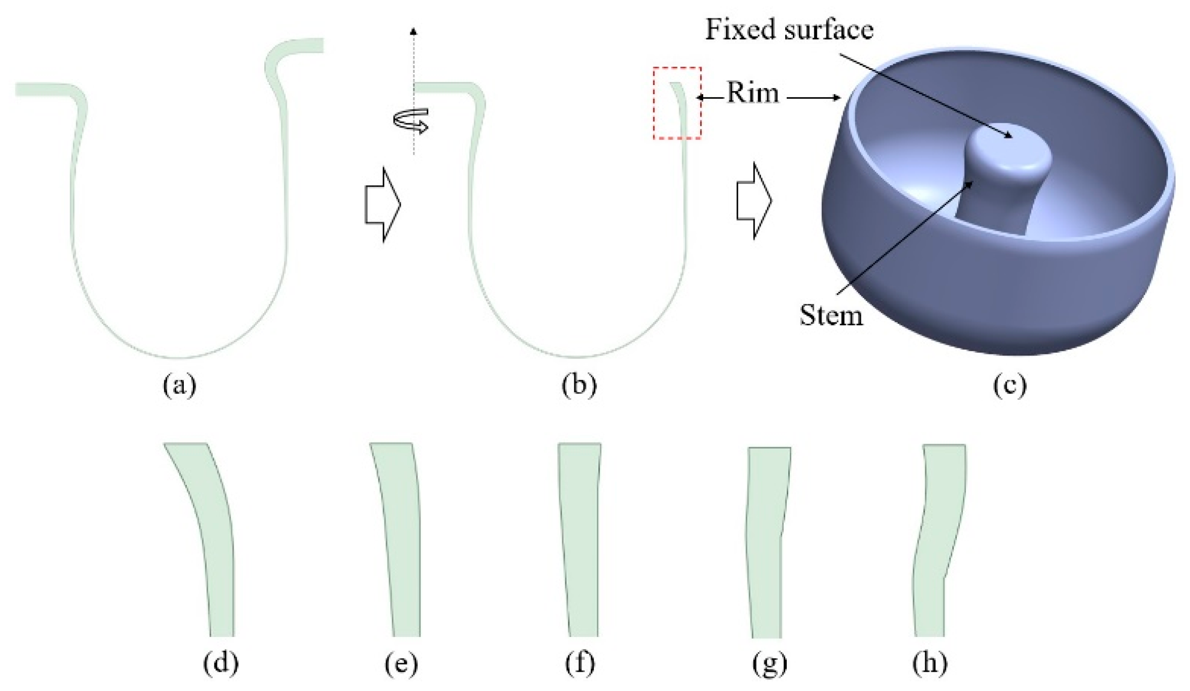
8]. In our simulation, we trimmed the two-dimensional deformed feature and then revolved it along the symmetric axis to create a shell resonator, as shown in figure 2 (a) ~ (c). An increasing in heat loss due to the greater contact area at the mold’s edge and reduced heat flux at the side of the Gaussian heat source lead rim(dashed red box in (b)) to bend. In other words, rim bending can be controlled by adding a chamfer where rim is formed.
Figure 2(d)~(h) show the change of the rim bending as the feature of the mold’s chamfer.
From the simulated various shell resonators, we analyzed its vibrational modes and calculated parameters such as effective mass, angular gain, and anchor loss. When the one side of the stem is fixed as shown in
Figure 3, the resonator exhibits multiple vibrational modes, and we are particularly interested in the n=2 wine-glass mode due to its high quality factor. This mode is being considered for use as a gyroscope [4~6,8]. FEM is suitable way for analyzing the resonator’s vibrational modes, and FEM software can provide us with the eigen frequencies and the deformation of each element for each eigen mode. In our case, we gathered deformation data for each element related to the n=2 mode to calculate the effective mass and angular gain of a shell resonator as given by
where ϕ and ρ represent normalized deformation vector and density [
16]. The subscription of x,y,z and 1,2 denote the motion axes and mode index for orthogonal vibrations in n=2 wine-glass oscillations.
The vibrational energy of a resonator gradually dissipates, and the quality factor is defined as the ratio of the energy stored to the energy dissipated per oscillation period. A high-quality factor of a resonator indicates low energy dissipation. In the case of a shell resonator, anchor loss can be a significant source of energy dissipation [
12,
17,
18]. Anchor loss refers to the energy loss resulting from the mechanical wave propagation from the resonator into the substrate. Therefore, it is important to design the glass-blowing process in a way that minimizes anchor loss since anchor loss is strongly depends on the geometrical parameters of a shell resonator. FEM is also useful to calculate anchor loss by applying a PML (Perfectly Matched Layer) around resonator’s substrate. The PML has perfectly matched impedance to the problem space including a damping factor. In other words, the mechanical wave enters to PML without any reflection and their energy is attenuated as propagating in PML. However, only reflected wave that occurs at the outer boundaries of the PML, can potentially lead to an underestimation of energy loss. Therefore, we set the PML size to be larger than 30 times the stem radius and to have enough nodes in a wave length [
18].
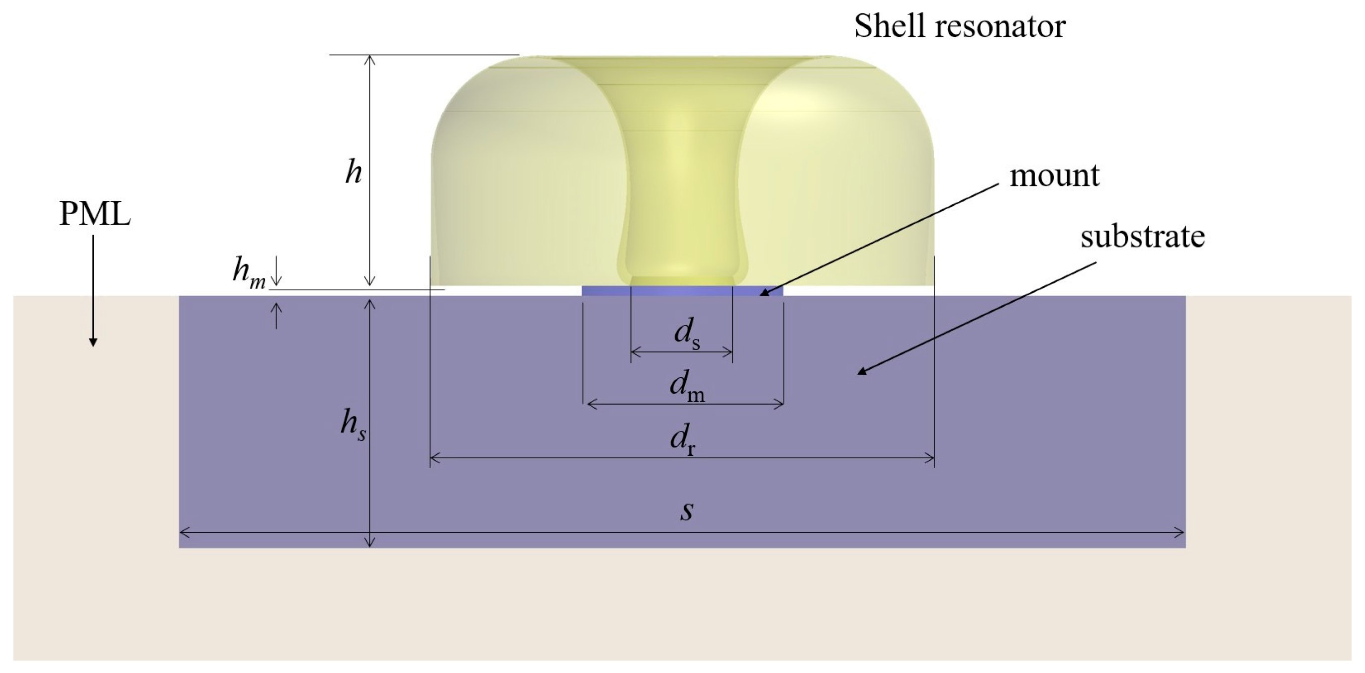
Figure 3 shows a shell resonator on its mount, substrate and PML for calculating the anchor loss in our case. In our case, the maximum diameter of a shell resonator is 10 mm which matches the mold’s inside dimeter. The height of a resonator varies with the vacuum pumping time in other words simulation time. A cylindrical mount and a square substrate are assumed to be made of fused silica, and their geometrical dimensions are shown in
Figure 3.
3. Results
Through the FEM simulation, we tested two solutions to get rid of rim’s bending. One is to use short-stem mold and another is to use optimized chamfer mold. We also compared the resonator’s performance by considering noise factor of shell resonators. We found out that the optimized chamfer mold gives less mechanical noise of a resonator than short-stem mold. The simulation results and experimental results of measuring Q factor of a shell resonator manufactured by the optimized chamfer are following.
3.1. Simulation resultss
Throughout our entire simulation process based on FEM, we can calculate the effective mass, resonant frequency, angular gain, and quality factor of a shell resonator for the wine-glass vibration mode. And then we defined mechanical noise factor as
from
of a shell resonator. In addition to having a lower
for the reduced noise, the capacitance between a resonator and electrodes should also be taken into consideration. Various types of electrodes were employed for the purpose of detecting and controlling a shell resonator [4~6, 17]. Among these, the 3-dimensional electrodes positioned around the rim of a shell resonator exhibited the highest detection and control efficiency [
19]. In this paper, we are specifically focusing on the use of 3-dimensional electrodes. As shown in
Figure 2 (d)~(h) and also in reference 14, we can observe the bending of the rim toward the stem. This bending phenomenon can be attributed to an increase in heat loss due to the greater contact area at the mold’s edge and reduced heat flux at the side of the Gaussian heat source. The bent rim could significantly reduce the capacitance between a resonator and the 3-dimensional electrodes, as the distance between the rim and the electrodes is increased. Any solution can be considered to avoid bent rim such as using spatially wide flame and controlling mold temperature high. And extensive polishing with shortened stem part in mold can be easily adopted in experiments. In this paper, we suggest another way to avoid bent rim by using chamfered mold. When the mold edge has a chamfer, we can see the changing of bending and optimize chamfer size. Through simulation, we were able to find an appropriate chamfer size that prevents the bending of the rim, and the final chamfer size was set to 1.0-0.8 mm in horizontal-vertical direction. If the chamfer size exceeds optimized value, the rim bends outward from the resonator’s stem which is also leads to decrease the capacitance.
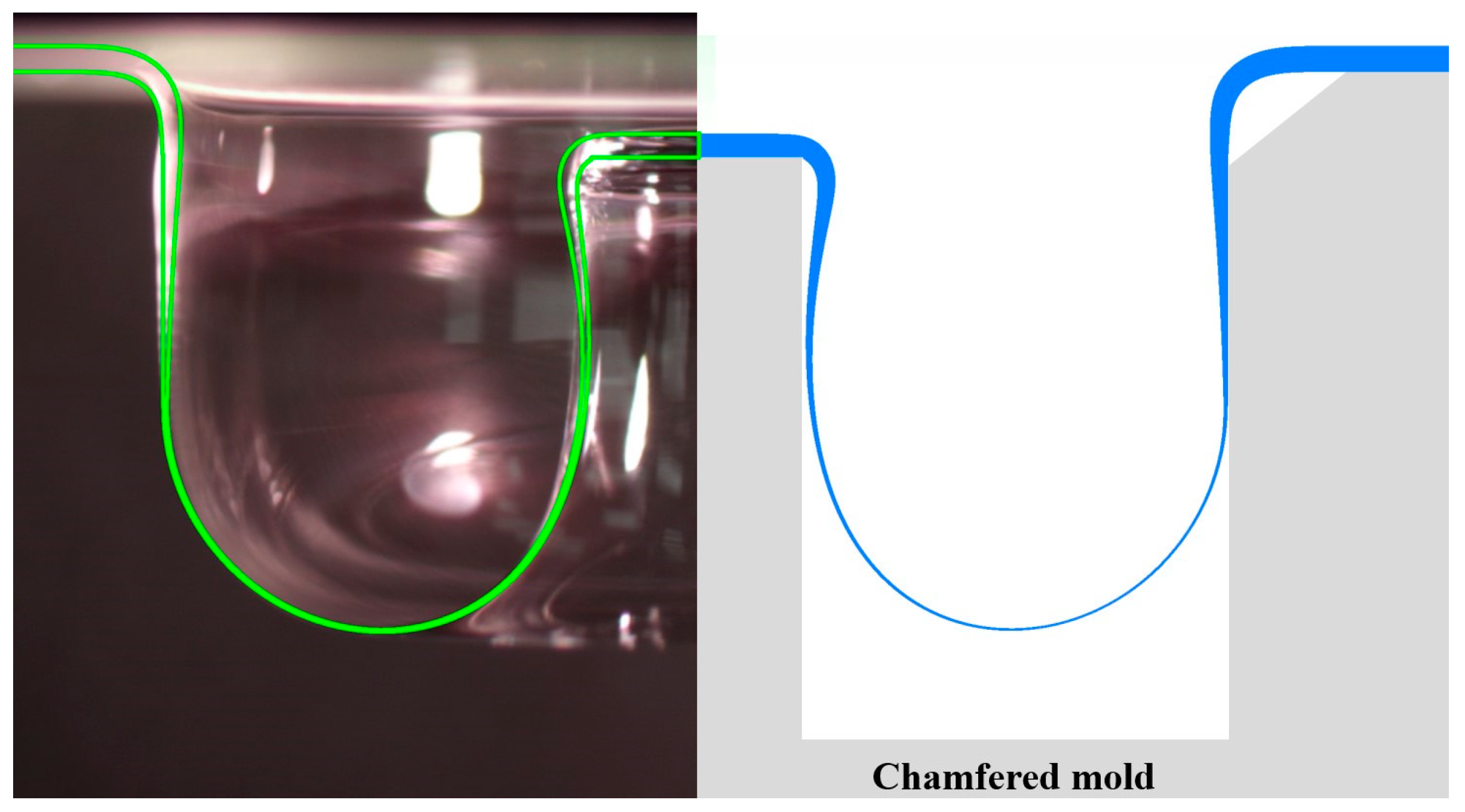
Figure 4 shows the comparison between the experimental result and the simulation result of glass blowing when the mold chamfer is optimized. The left side shows the glass-blown fused silica where the substrate has 250 μm in the thickness. The right side shows the simulation result when the mold temperature is set to 300 K and the thermal heat source has 10 mm in the Gaussian waist. The green line in the left side represents the outline of the right-side result for a good comparison. This demonstrates that the simulation result closely matches the actual experimental outcome for the glass blowing.
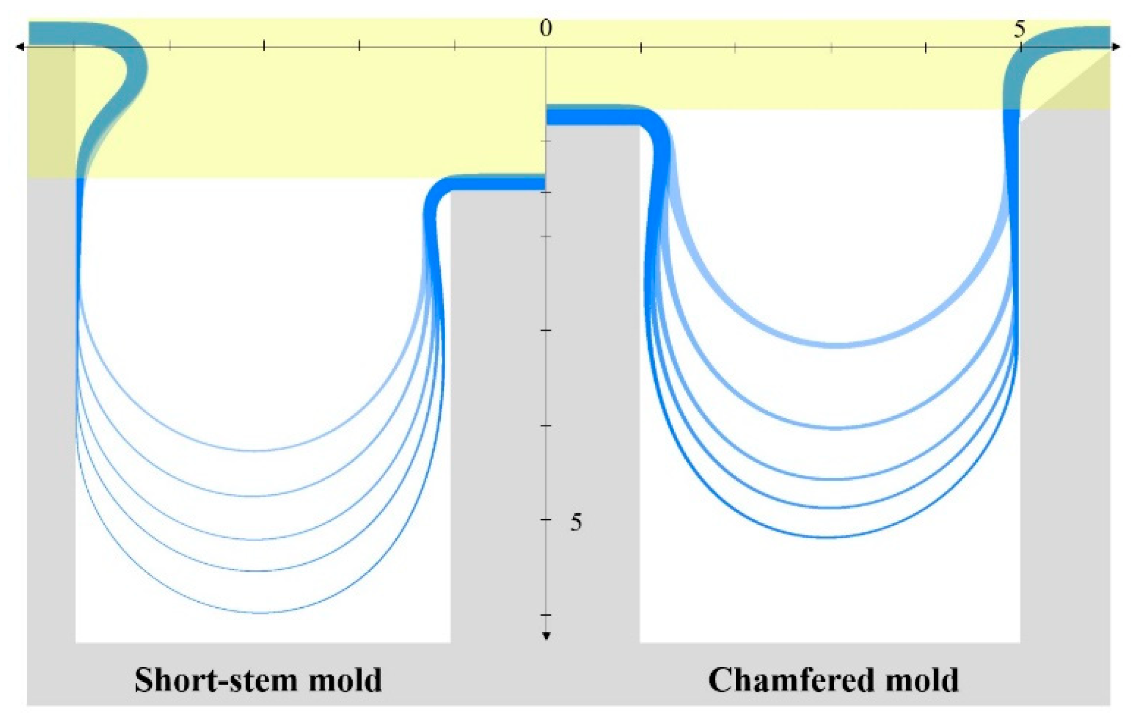
Figure 5 shows simulation results of glass blowing as the height of formed glass substrate for a shorten stem mold and chamfered mold. During the simulation, the mold temperature set to room temperature (300 K). The fused silica substrate has a thickness of 250 μm. The column’s height for the short-stem mold is set 0.75 mm lower than the chamfered mold to eliminate the bent rim through polishing. The light-yellow region in the figure represents the polishing area. Simulation results show the deformation of the glass substrate as a function of pumping time, and both methods confirm the ability to avoid a bent rim.
However, there are differences in the shapes formed by the two molds, with the short-stem mold exhibiting thinner rim thickness and a thinner connection between the stem and rim compared to the chamfered mold. To quantitatively compare the gyroscope performance of resonators, we calculated the noise factor of the resonators produced in each mold.
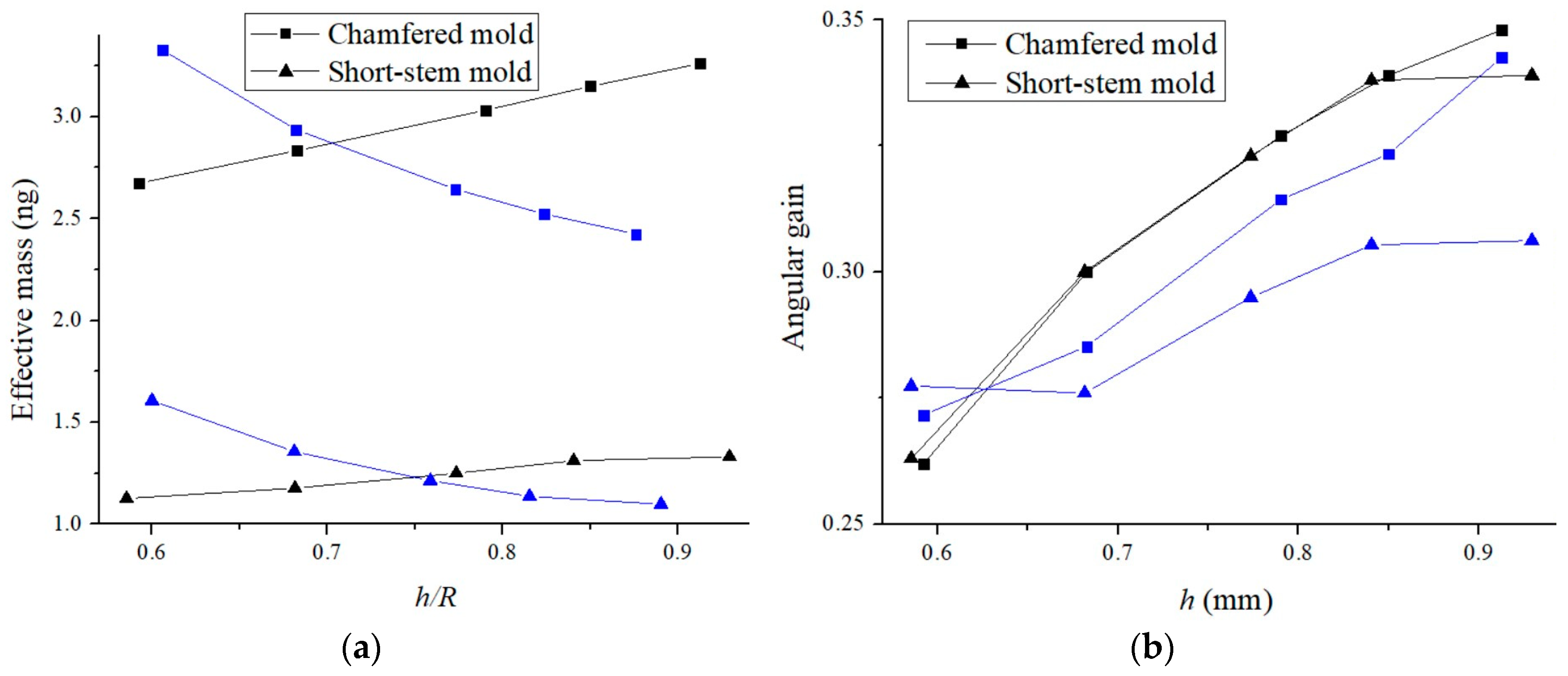
Figure 6 (a) shows the effective mass and resonant frequency of a shell resonator for the wine-glass vibration mode as its relative height with a short-stem mold and a chamfered mold. A resonator produced by both molds exhibits clear trend in the change of effective mass and eigenfrequency as a function of the resonator’s height. For a shell resonator, increasing resonator’s diameter, height and thickness of the rim increases the effective mass [
18]. The eigenfrequency of a shell resonator is proportional to the thickness and inversely proportional to the height [
17]. As a result, we can see that the resonant frequency decreases with increasing height for both mold types. At the same resonator’s height, the resonator produced with the chamfered mold is thicker compared to the resonator produced with the short-stem mold, resulting in the chamfered mold resonator having a larger effective mass and a higher absolute resonant frequency.
Figure 6 (b) shows changes of the angular gain and the quality factor related to the anchor loss as the resonator’s height. The quality factor in log scale is normalized by the value of the highest resonator produced by the short-stem mold. Since a taller resonator leads to higher angular gain [
17], the angular gain is increasing as the height for both types of molds. And the absolute value of angular gains for two molds are similar above 3 mm in height. We can also see that the quality factor is higher for the resonator produced by the chamfered mold compared to the short-stem mold, as the anchor loss decreases with the rim thickness. In here, thermoelastic damping, which is another dominant damping mechanism, is not taken into account, as the rim’s thickness is not the dominant factor affecting thermoelastic damping when the radius remains constant [
17,
20].
To prevent rim bending which leads to decrease the capacitance between the resonator’s rim and 3D electrodes, using the chamfered mold also enables us to maintain a thicker rim for the resonator compared to using a short-stem mold. The thicker rim leads to an increase in the resonator’s effective mass, eigenfrequency, angular gain, and quality factor, consequently reducing the noise factor.
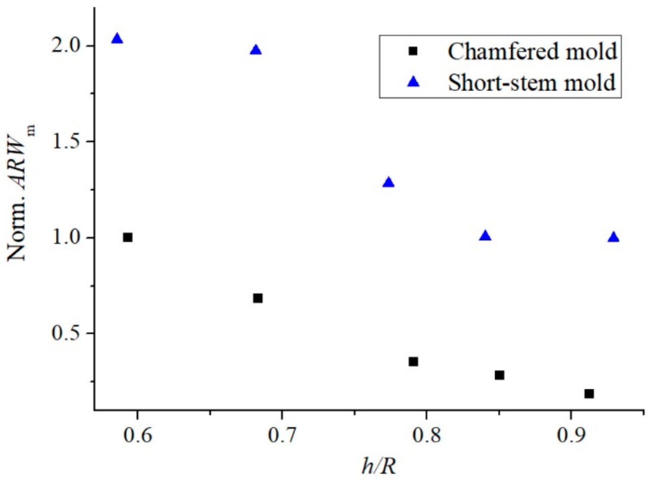
Figure 7 shows the normalized noise factor as a function of the resonator’s height for the two mold types. To calculate the normalized noise factor, all values are normalized using the values of the highest one produced by the short-stem mold in figure 4. It shows that the noise factor decreases with the resonator’s height, and height is the dominant factor for both types of molds. Although the angular gain may not differ significantly for both molds, we can anticipate a meaningful lower noise level by using a chamfered mold at the same height since other factors are decreased. It’s important to note that these results are based on the assumption that the mold has a constant room temperature. The absolute values will change with variations in the mold temperature. Furthermore, it should be noted that increasing the chamfer size can induce rim bending in the opposite direction, outward. Despite these simulation situations, the chamfered mold can be readily implemented in shell resonator production systems.
3.2. Manufactruing a shell resonator with chamfered mold
As we suggested to use chamfer mold, we manufactured shell resonators by using chamfered mold which has 1.0-0.8 mm chanmfer for horizontal and vertical direction, respectively.
Figure 8 shows the manufacturing process [
8]. We used flame from propane and oxygen gas torch as heat source. The flame heats a fused silica substrate. When the temperature of substrate reaches to its softening temperature and a vacuum pump is turned on. The soft substrate is deformed to 3 dimensional shape under pressure for few seconds. The inside of deformed substrate is metal coated with about 350 nm thick Al layer and the outside is coated with Cr-Au-Al layers. The coating thicknesses are 8 nm and 12 nm for Cr and Au, respectively. After metalizing, next step is to remove unwanted part. Ways to remove unwanted part were reported by using chemical, CMP. laser and laser assisted etching [
21,
22,
23] and we used CMP in this research. The substrate is fitted to the CMP jig by thermal polymer. A CMP process removes unwanted substrate and then a metal coated shell resonator is finally made after etching away the polymer and the Al layers.
Figure 9 shows a size (
in
Figure 3) distribution of resonators for continuous manufacturing with non-chamfer mold and 1.0-0.8 mm mold when the mold diameter is 10 mm. It is clear that the appropriate chamfer reduces rim’s bending and gives us closely straight rim. The size of 13 resonators is measured to 9.94±0.01 mm with a 1.0-0.8 mm chamfered mold and 9.11±0.04 mm.
The metalized resonator is mounted on the rotation stage in vacuum chamber to measure its vibrational characteristics. The laser beam that hits the resonator and then is retro-reflected consists of an optical interferometer to measure resonators tiny displacement during vibrations. By detecting interferometric phase change as of resonator’s displacement, we optically measured key factors of resonators that reflect its performance, such as the resonant frequency of wine-glass vibrating mode, the frequency difference between the primary and the secondary axes, Q-factor and the difference in Q-factor [
8,
9,
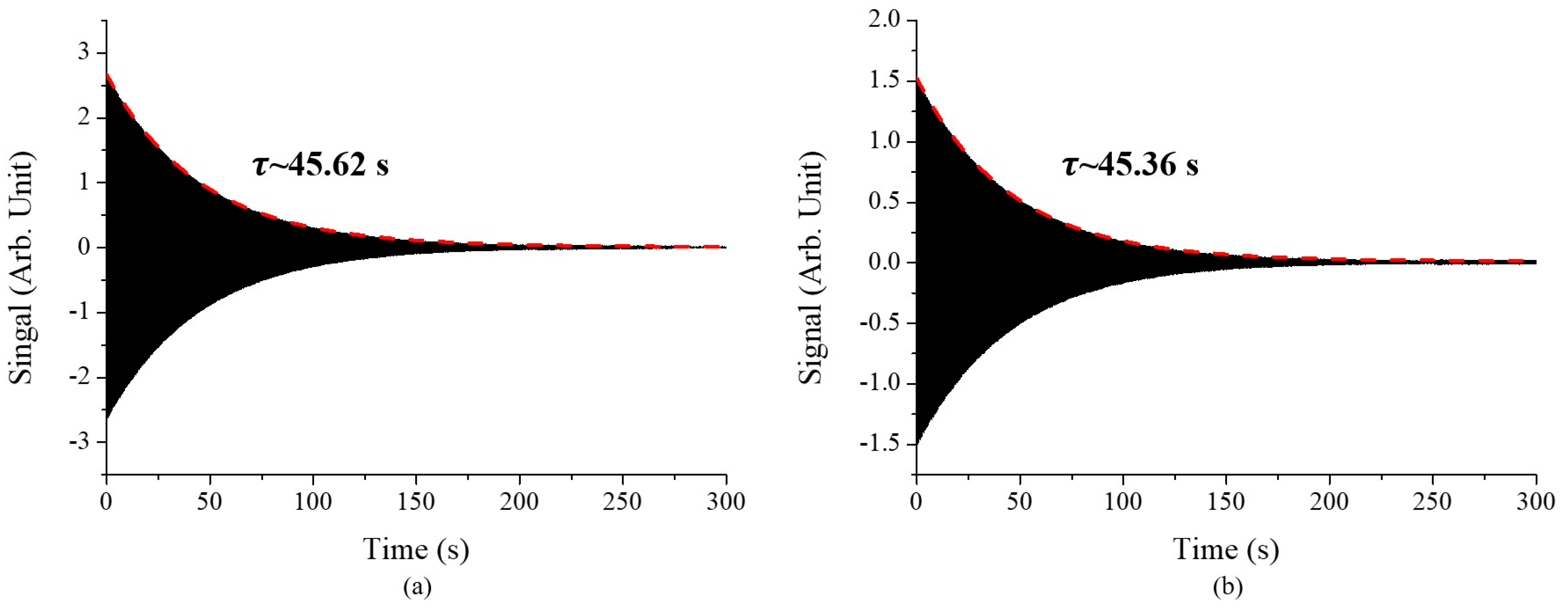
24]. The resonant frequency was measured by monitoring the vibrational amplitude of a resonator as buzzer’s operating frequency which excites the resonator’s vibration as shown in figure 8. And then Q-factor was also obtained by detecting ring down time,
where
is a decay time and
is a resonant frequency.
Figure 10 shows the ring down signal of a metalized resonator manufactured with chamfered mold for two axes in a vacuum chamber. The vacuum pressure was 5.0e-4 mbar in our case. Q-factors were measured to 622,466 and 619,973. The resonant frequencies were also measured to 4,343 and 4,350 Hz. In our case the frequency difference between two axes is about 7 Hz and 0.4% Q factor difference.
4. Discussion
A shell resonator is a key component in MRIG technology. The geometric features of the resonator should be designed with considering its gyroscope performance. In this simulation work, we simulated a process of glass-blowing to model a 3-dimensional shell resonator and calculated resonator’s four parameters - effective mass, eigenfrequency, angular gain and anchor loss - by using a finite elements method. This allowed us to predict the resonator’s performance. We showed that the final feature of blown glass depends on the shape of mold. Our calculations regarding the resonator’s noise factor have shown that using a chamfered mold is advantageous for achieving a lower noise level and effective capacitive detection and control in a shell resonator functioning as a gyroscope. This is achieved by enabling the maintenance of a thicker rim for a resonator and preventing rim bending, as compared to using a short-stem mold. We also experimentally demonstrated that the chamfered mold was well applied to make rim straight with 0.13% size deviation. This work will assist us in getting insight into understanding a shell resonator as a gyroscope, designing a mold and determining experimental conditions for achieving higher performance.
Author Contributions
Conceptualization, Hoon Yu and Tae-Yoon Kwon; simulation, Hoon Yu; writing—original draft preparation, Hoon Yu; writing—review and editing, Tae-Yoon Kwon; visualization, Hoon Yu; setup for manufacturing and measuring system, Hoon Yu and Taeyun Kim; operating experimental systems, Taeyun Kim; managing experimental systems, Taeyun Kim and Seongmin Ju; project administration, Tae-Yoon Kwon and Seongmin Ju; funding acquisition, Tae-Yoon Kwon All authors have read and agreed to the published version of the manuscript.
Funding
This research was supported by the Challengeable Future Defense Technology Research and Development Program through the Agency for Defense Development(ADD) funded by the Defense Acquisition Program Administration in 2023(No.915023201).
Data Availability Statement
All dataset were generated during the study.
Acknowledgments
Authors thank to Optonics for their collaboration in the manufacturing of shell resonators, as well as their advanced expertise in controlling manufacturing conditions, glass polishing, and cleaning.
Conflicts of Interest
The authors declare no conflict of interest.
References
- Passaro V. M., N.; Cuccovillo, A.; Vaiani, L.; De Carlo, M.; Campanella C., E. Gyroscope Technology and Applications: A Review in the Industrial Perspective. Sensors 2017, 17, 2284. [Google Scholar] [CrossRef] [PubMed]
- El-Sheimy, N.; Youssef, A. Inertial sensors technologies for navigation applications: state of the art and future trends. Satellite Navigation 2020, 1, 2. [Google Scholar] [CrossRef]
- Zhanshe, G.; et al. Research development of silicon MEMS gyroscopes: a review. Microsystem Technologies 2015, 21, 2053–2066. [Google Scholar] [CrossRef]
- Singh, S.; Woo J., K.; He, G.; Cho J., Y.; Najafi, K. 0.0062 ∘/hr−−√ Angle Random Walk and 0.027 ∘/hr Bias Instability from a Micro-Shell Resonator Gyroscope with Surface Electrodes. 2020 IEEE 33rd International Conference on Micro Electro Mechanical Systems (MEMS) Vancouver, BC, Canada, 2020, 737-740.
- Sun, J.; et al. Investigation of Angle Drift Induced by Actuation Electrode Errors for Whole-Angle Micro-Shell Resonator Gyroscope. IEEE Sensors Journal 2022, 22, 3105–3112. [Google Scholar] [CrossRef]
- Asadian M., H.; Wang, D.; Shkel A., M. Fused Quartz Dual-Shell Resonator Gyroscope. Journal of Microelectromechanical Systems 2022, 31, 533–545. [Google Scholar] [CrossRef]
- Delhaye, F. HRG by SAFRAN: The game-changing technology. 2018 IEEE International Symposium on Inertial Sensors and Systems (INERTIAL), Lake Como, Italy, 2018, 1-4.
- Yu, H.; Kwon T., Y. Measurement of vibrating modes for a shell resonator by using dual-interferometers. Review of Scientific Instruments 2023, 94, 035011. [Google Scholar] [CrossRef] [PubMed]
- Singh, S.; Nagourney, T.; Cho J., Y.; Darvishian, A.; Najafi, K.; Shiari, B. Design and fabrication of high-Q birdbath resonator for MEMS gyroscopes. 2018 IEEE/ION Position, Location and Navigation Symposium (PLANS) Monterey, CA, USA, 2018, pp. 15–19.
- IEEE Standard Specification Format Guide and Test Procedure for Coriolis Vibratory Gyros, IEEE Standard 1431, 2004.
- Darvishian, A.; et al. Effect of Electrode Design on Frequency Tuning in Shell Resonators. 2019 IEEE International Symposium on Inertial Sensors and Systems (INERTIAL), Naples, FL, USA, 2019, 1-4.
- Chen, Y.; et al. Simulated analysis of forming imperfection for micro shell resonators. Microsystem Technologies 2021, 27, 723–737. [Google Scholar] [CrossRef]
- Chen, Y.; Xi, X.; Shi, Y.; Lu, K.; Xiao, D.; Wu, X. Simulated Prediction of Structural Asymmetry for Glass Blown Micro Shell Resonators. 2020 IEEE International Symposium on Inertial Sensors and Systems (INERTIAL), Hiroshima, Japan, 2020, pp. 1–4.
- Asadian M., H.; Noor R., M.; Shkel A., M. Simulation-Based Approach in Design of 3D Micro-Glassblown Structures for Inertial and Optical Sensors. 2019 IEEE SENSORS, Montreal, QC, Canada, 2019, pp. 1–4.
- Shiari, B.; Nagourney, T.; Darvishian, A.; Cho J., Y.; Najafi, K. Simulation of Blowtorch Reflow of Fused Silica Micro-Shell Resonators. Journal of Microelectromechanical Systems 2017, 26, 782–792. [Google Scholar] [CrossRef]
- Cho J., Y.; Woo J., K.; Yan, J.; Peterson R., L.; Najafi, K. Fused-Silica Micro Birdbath Resonator Gyroscope (μ -BRG). Journal of Microelectromechanical Systems 2014, 23, 66–77. [Google Scholar] [CrossRef]
- Darvishian, Design and Analysis of Extremely Low-Noise MEMS Gyroscopes for Navigation. Ph.D. thesis, University of Michigan, Michigan, 2018.
- Darvishian, A.; Shiari, B.; Cho J., Y.; Nagourney, T.; Najafi, K. Anchor Loss in Hemispherical Shell Resonators. Journal of Microelectromechanical Systems 2017, 26, 51–66. [Google Scholar] [CrossRef]
- Darvishian, A.; et al. Effect of Electrode Design on Frequency Tuning in Shell Resonators. 2019 IEEE International Symposium on Inertial Sensors and Systems (INERTIAL), Naples, FL, USA, 2019, 1-4.
- Darvishian, A.; Nagourney, T.; Cho J., Y.; Shiari, B.; Najafi, K. Thermoelastic Dissipation in Micromachined Birdbath Shell Resonators. Journal of Microelectromechanical Systems 2017, 26, 758–772. [Google Scholar] [CrossRef]
- Singh, S.; Cho J., Y.; Najafi, K. Low-Cost, High-Throughput Process Using HF Acid to Singulate Fused-Silica Shell Resonators with High-Q. 2020 IEEE International Symposium on Inertial Sensors and Systems (INERTIAL), Hiroshima, Japan, 2020, pp. 1–4.
- Li, W.; et al. A Novel High Transduction Efficiency Micro Shell Resonator Gyroscope With 16 T-Shape Masses Using Out-of-Plane Electrodes. IEEE Sensors Journal 2019, vol. 19, no. 13, pp. 4820-4828. [CrossRef]
- Zhao, T.; Zhuo, M.; Zhou, X.; Xi, X.; Wu, X.; Xiao, D. Fused Silica Gyroscope Resonator Manufactured With Femtosecond Laser Assisted Wet Etching. Journal of Microelectromechanical Systems 2022, 31, 315–317. [Google Scholar] [CrossRef]
- Senkal, D.; Shkel A., M. Whole-Angle MEMS Gyroscopes: Challenges and Opportunities. IEEE Press with John Wiley & Sons, 2020, ISBN-13: 978-1119441885.
|
Disclaimer/Publisher’s Note: The statements, opinions and data contained in all publications are solely those of the individual author(s) and contributor(s) and not of MDPI and/or the editor(s). MDPI and/or the editor(s) disclaim responsibility for any injury to people or property resulting from any ideas, methods, instructions or products referred to in the content. |
© 2023 by the authors. Licensee MDPI, Basel, Switzerland. This article is an open access article distributed under the terms and conditions of the Creative Commons Attribution (CC BY) license (http://creativecommons.org/licenses/by/4.0/).

