1. Introduction
Under the trend of increasingly tight global connectivity, the environment and political landscape of Arctic waters have undergone complex changes with the developments in the 21st century [
1]. The Arctic has not only enormous economic value but also very important military value. For China, it holds an important geostrategic position. Currently, the Arctic has become a new channel for maritime trade, a new space for resource development, and a new battlefield for great power games [
2]. A rudder device is of great significance for the maneuverability and vitality of underwater vehicles. Under the action of low Arctic temperatures and long-term alternating loads, the efficiency of the rudder decreases, and the underwater vehicle turns slowly [
3]. The fatigue life of its rudder mechanism has been severely tested, and once a brittle fracture occurs, it will cause irreparable losses. Underwater vehicles in our country have experienced rudder stem breakage accidents, and the designed lifespan of such rudders is generally approximately 3000 hours [
4]. However, the fatigue problem of the rudder stem mechanism at low temperatures has not been given sufficient attention. Therefore, studying the fatigue performance of underwater vehicle rudder mechanisms at low polar temperatures is of great research significance and practical value.
Fatigue damage is one of the main forms of mechanical structure failure. Fatigue damage occurs in a variety of equipment and is very common. If the equipment is damaged and not subject to timely maintenance and replacement, then this often causes unpredictable consequences, so fatigue issues have attracted wide attention. When a material or a structure is subjected to frequent alternating loads, even if the stress is lower than the yield limit, fatigue of the structure or damage could occur. Fatigue failure is the main form of failure for parts working under variable stress. When a component fails due to fatigue fracture, the variable stress it experiences is much smaller than the static stress value during static tensile fracture. The vast majority of machines or parts in mechanical operation work under alternating loads; thus, fatigue analysis of parts and component structures is essential, and fatigue analysis is related to the type of load, stress-strain characteristics, fatigue limit, fatigue S-N curve, and other characteristics.
The rudder of an underwater vehicle consists of an elevator and a rudder, and the rudder device is mainly arranged outside the pressure-resistant steering engineering room and pressure-resistant shell. An elevator is a device for underwater vehicles to maintain and change depth and is mainly divided into a front elevator and a tail elevator. The rudder blades of the first elevator are symmetrically arranged on both sides of the front or command room enclosure, with a smaller rudder surface and less rudder force. The rudder blades of the tail elevator are symmetrically arranged on the front (or rear) surface of the shaft propeller. The rudder blade surface is larger than that of the front rudder and is directly affected by the water flow of the propeller, generating a greater rudder force. It is the main elevator for underwater operation. The mechanical part of the rudder is used alone with the electrical control part of the steering subsystem or in conjunction with the tail elevator to maintain or change the depth and pitch attitude of the underwater vehicle [
5]. Functionally speaking, the rudder is used to change or maintain the heading of underwater vehicles, while the elevator is mainly used to change or maintain the depth of underwater vehicles during navigation. The working principle is to change the attitude or state of underwater vehicles through the action of the rudder force and torque, thereby changing the force and achieving the goal of changing or maintaining the heading and depth [
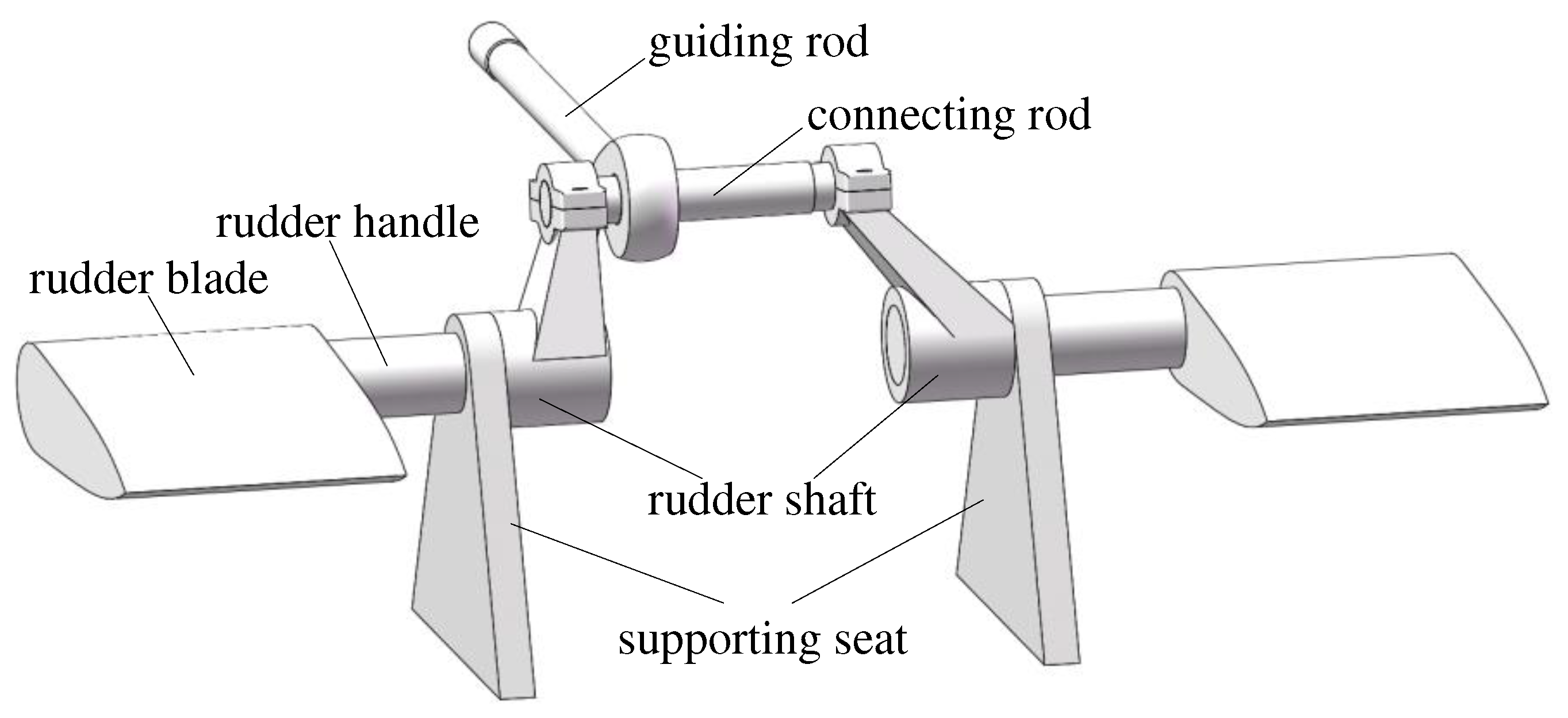
6]. Essentially, the control of the entire rudder device belongs to the position servo control system. Taking the elevator as an example, it consists of rudder blades, a rudder stock, a rudder handle, a guide rod, a guide device, a transmission rod, an implementing press, a hydraulic steering system, etc.
At present, research on the fatigue of polar ships by scholars both domestically and internationally mainly focuses on the fatigue problems of ship materials under ice-induced loads and low-temperature conditions. The analysis methods mainly include theoretical analysis and experimental research. In terms of theoretical analysis, the fatigue life of different materials and structures is mainly predicted and evaluated by finite element analysis and other methods (numerical simulation and experimental analysis). In terms of experimental research, fatigue life is mainly studied and verified through experimental testing and data collection. CL Walters [
7] carried out Charpy impact and low-temperature fatigue crack growth tests on S460 structural steel and concluded that the fatigue of the material at the ductile-brittle transition temperature has a very different fatigue crack growth rate than the fatigue above this temperature. Alvaro [
8] reviewed the fatigue properties of steels at low temperatures, noted the effects of low temperatures on different aspects of the fatigue life of steels and their weldments, and verified the necessity of low-temperature fatigue testing of materials. Subsequently, Alvaro [
9] conducted experimental research on the fatigue behavior of Q420 high-strength steel under different stress amplitudes and temperatures through impact and strength tests. The results showed that Q420B steel met the requirements of impact and strength tests, and low temperatures improved the fatigue performance of the material to a certain extent. Fatigue fracture occurred at higher stress amplitudes and decreased with decreasing temperature.
Kabakcioglu [
10] discussed the effects of the sea state, environmental conditions, and materials on the fatigue performance of ships, emphasizing that fatigue analysis and life cycle prediction are critical for structural integrity calculations of naval ships and vessels. The study focused on fatigue calculations and life prediction using the Palmgren-Miner method, and it concluded that consideration of the fatigue life prediction in the early design stage can help identify the critical locations of potential fatigue cracks. A S Mujahid [
11] emphasized that predicting the fatigue life of the rudder bar of a ship is critical, and his study was conducted on an LCT ship for the transverse rocking motion of the ship. Numerical simulation, calculation of rudder bar bending stresses, and application of the Palmgren-Miner formula were used to predict the fatigue life, and the fatigue life of the rudder bar was predicted to be 1.8 years. Braun[12, 13] et al. comprehensively reviewed the current state-of-the-art methods for evaluating the high-period fatigue strength of steel structures at subzero temperatures, outlined how the effect of temperature on fatigue strength is taken into account when designing steel structures, and experimentally analyzed the effect of subzero temperatures on the fatigue strength of ordinary and high-strength steel structures. Wang [
14] et al. studied the low-temperature fatigue properties of EH36 steel used in polar icebreakers, and their experimental results showed that EH36 steel has good impact toughness and low-temperature resistance and that the fatigue crack growth rate of EH36 steel at low temperatures is low compared with that at room temperature, which suggests that it has good resistance to crack initiation and growth at low temperatures. Wang [
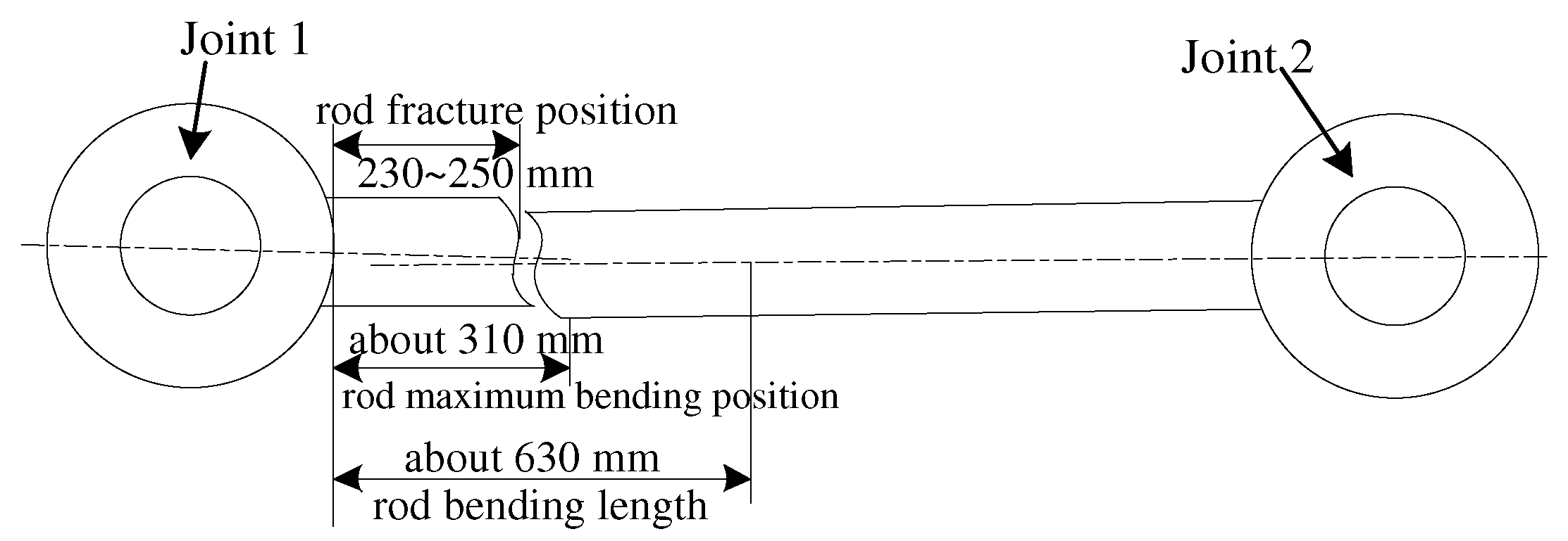
15] analyzed the cause of rudder tie rod fracture at room temperature of a certain type of ship.
Figure 1 shows a schematic diagram of tie rod fracture, and its analysis results show that there is a foreign object between the tie rod and the rudder rod mechanism, resulting in the rudder movement process of the tie rod exhibiting localized larger displacement changes, which ultimately cause the fracture.
In conclusion, research on fatigue, especially low-temperature fatigue, is mainly focused on material research and the fatigue of platforms and hull structures under low-temperature loads, while there is very little research on the low-temperature fatigue of mechanical structures outside sealed cabins of underwater vehicles. Chen [
16] and his research group analyzed the static strength and fatigue life of the submarine rudder mechanism under low Arctic temperatures and found that the fatigue hot spot of the mechanism is located at the joint between the guide rod and the connecting rod. I participated in the experimental design. To further study the fatigue performance of the rudder system at low temperatures, this article conducts simulation and experimental analysis specifically for the weak components with a short lifespan in the mechanism.
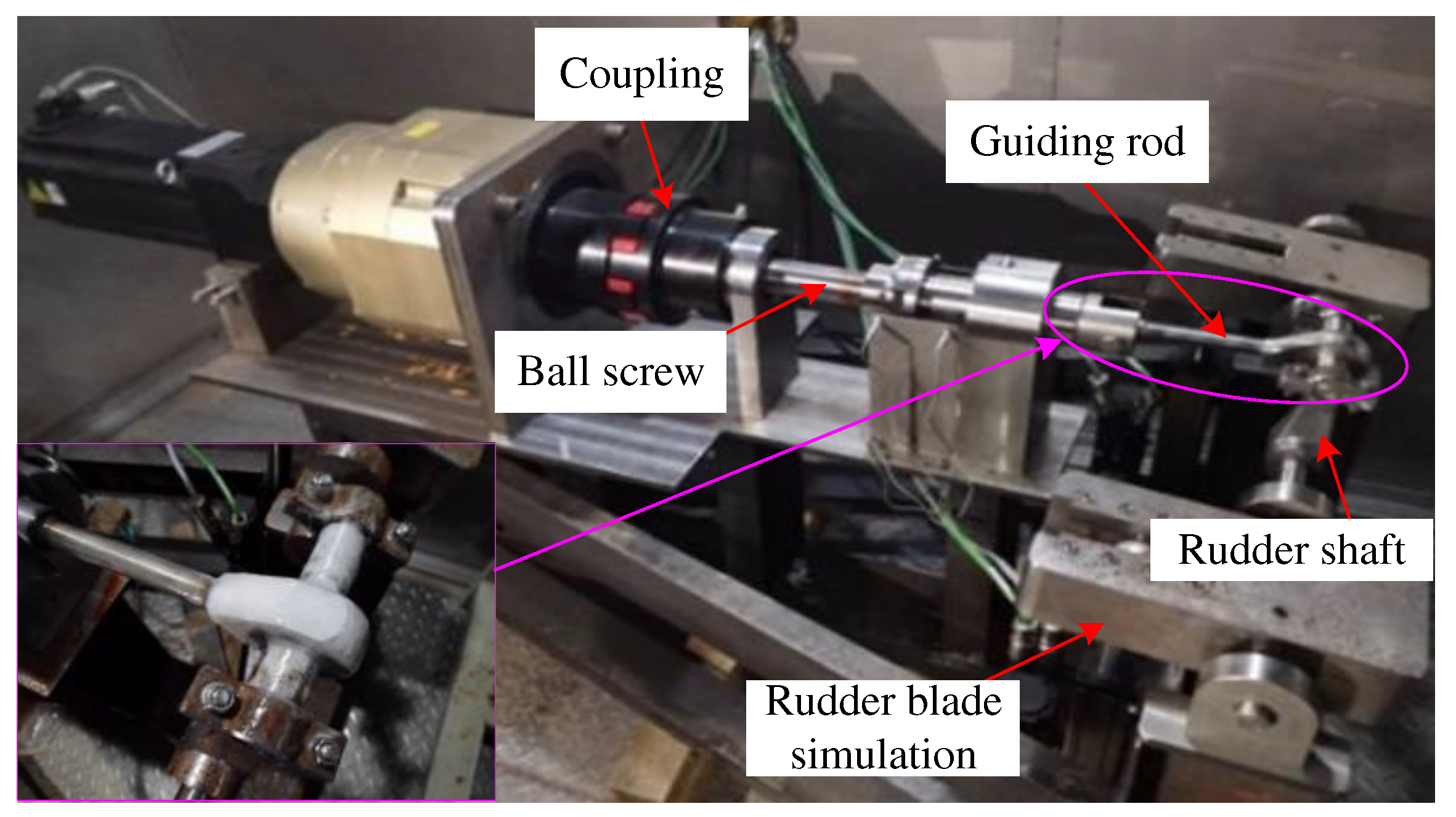
However, existing research still has some shortcomings, such as differences between theoretical models and actual operating conditions, and insufficient experimental data. Because the rudder stock mechanism of underwater vehicles is located in a nonwatertight area outside the pressure-resistant shell, there is a possibility of floating ice entering the gap between the rudder stock mechanisms in the Arctic region. In addition, there is a large amount of aged ice on the Arctic ice surface, and its hardness can reach Mohs hardness level 6 at low temperatures of -60 °C. Once floating ice becomes stuck in the trajectory of the rudder stock, it may cause the pull rod to break or even become stuck, resulting in a fatal failure. At present, fatigue testing of underwater vehicle structures is still in the stage of computer simulation both domestically and internationally, and there is limited information available for reference. In addition, equipment that can meet the fatigue testing requirements of underwater vehicle rudder mechanisms has not yet been developed in China. Low-temperature fatigue testing is limited to the material level, and the testing conditions are relatively backward. Therefore, a testing machine is specially designed to simulate low-temperature operation in polar environments in a low-temperature environment laboratory and study the fatigue life of the rudder stock.
2. Introduction to the Rudder Mechanism
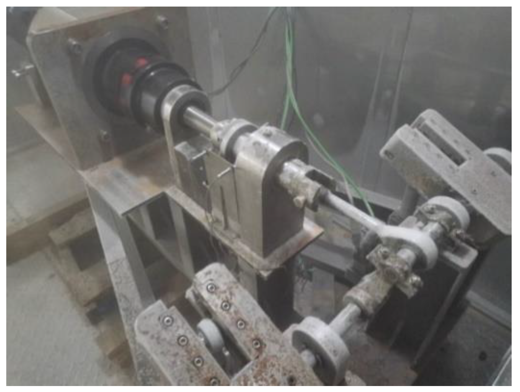
When underwater vehicles navigate, their volume and weight are fixed, but the buoyancy can be controlled by controlling the inflow and outflow of water, thereby controlling the depth of underwater navigation. Underwater vehicles control their direction and depth by manipulating the rudder handle. A schematic diagram of the elevator rudder mechanism is shown in
Figure 2. When the underwater vehicle needs to be lifted and lowered, the rudder handle is rotated, and the rudder surface angle changes, thereby changing the direction of the lifting and lowering of the underwater vehicle. When the rudder is facing upwards, the underwater vehicle will rise; when the rudder is facing downwards, the underwater vehicle will descend. At the same time, the watertight compartment of underwater vehicles is used to control the buoyancy of underwater vehicles. It can control the buoyancy of underwater vehicles by controlling the inflow and outflow of water. When an underwater vehicle needs to be lifted or lowered, the valve in the watertight compartment will open or close to control the entry and exit of water. When the valve of the watertight compartment is opened, water will enter the compartment, increasing the weight of the underwater vehicle and causing it to descend. In contrast, when the valve of the watertight compartment is closed, water will be discharged from the compartment, reducing the weight of the underwater vehicle and causing it to rise.
Through the research and review of information, it was found that the guiding rod of the rudder stock mechanism is composed of a rod head, a rod, and a joint connected by welding, and the composition of the structure is shown in
Figure 3. The rod head and joints for the ship are made of 925A forged steel, the rod material is ordinary 20 structural steel, and the welding material for the ship welding is 395. Considering the installation and positioning, here, the design to be welded to the installation is conducive to the assembly mechanism and positioning of the welding. Welding has a certain impact on the fatigue life of the welded structure mechanism, which may be due to the material properties, welding quality, and loading methods, such as the information of cracks in the structure. Therefore, it is considered that during manufacturing, installation, or use of the rudder mechanism, there may be some sudden changes in the geometry, material defects external damage, etc., which lead to the concentration of stresses in localized areas. These stress concentration points will become fatigue crack growth areas, and with time, the cracks will gradually expand, eventually leading to the failure of the mechanism. As an important component of the rudder system mechanism, structural stress analysis of the rudder bar is crucial to the entire mechanism.
4. Results Analysis
4.1. Simulation Results Analysis
As mentioned earlier, the rudder stock is welded from two materials, with the rudder stock head and joint made of 925A and the middle pull rod made of 20# steel. The density of 925A is 7.938 g/m
3, Young's modulus is 2.06e05, and the Poisson's ratio is 0.3. The density of 20# steel is 7.84 g/m
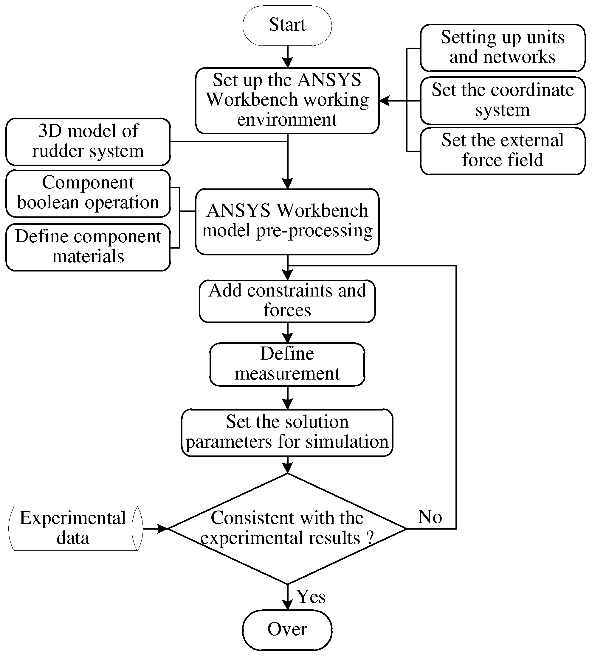
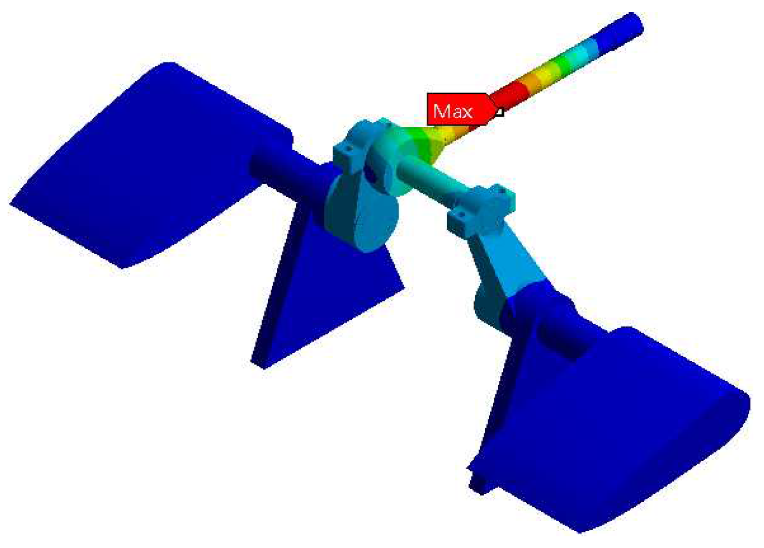
3, Young's modulus is 2.13e05, and the Poisson's ratio is 0.282. The first step in strength analysis is to perform static analysis on the structure. The static structure module is used for static analysis, and deformation and stress are set as solving terms. The results show the equivalent stress of the rudder system structure in a static state, as shown in
Figure 8.
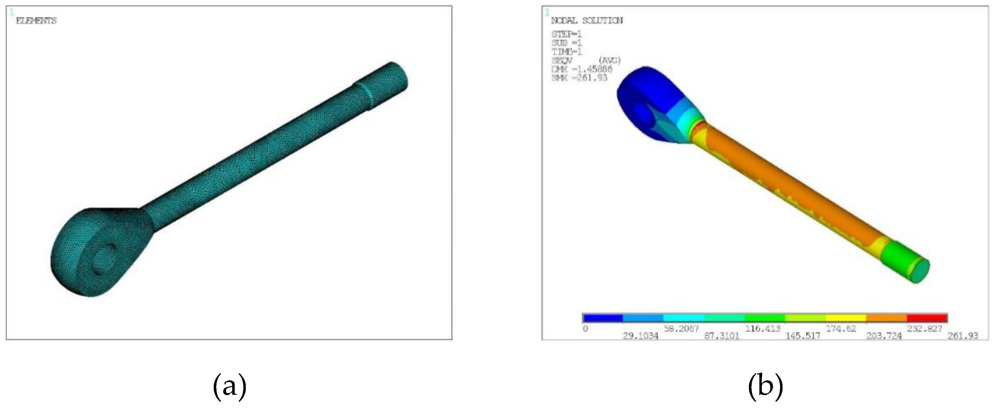
According to the stress map results, the maximum stress in the rudder structure is at the guiding tie rod, and static stress analysis and fatigue analysis are separately performed for this component. In ANSYS, mesh delineation and force analysis of the guiding tie rod are performed, and the results are shown in
Figure 9. The middle part of the tie rod has the highest stress, and its contact area with the tie rod head also presents the highest stress, which further indicates that the tie rod is the component of most concern.
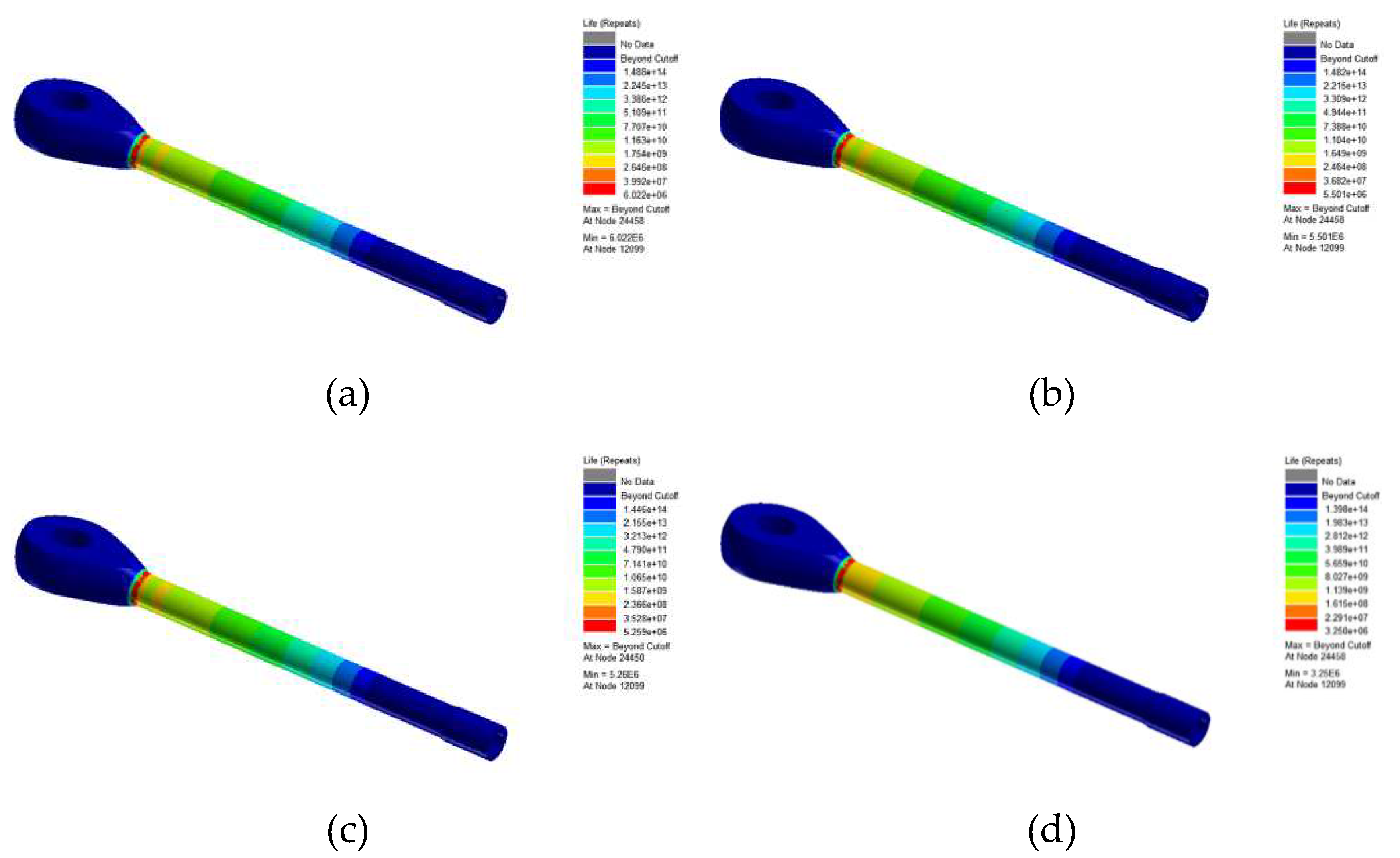
Considering the low-temperature environment, the components are imported into Ncode Designlife. The connecting head hole of the guide rod is fixed, pressure is applied to the other end of the joint, and its fatigue life under temperature conditions of room temperature, 0 °C, -20 °C, and -40 °C is simulated. Their simulation cloud diagrams are shown in
Figure 10.
The results of the simulation analysis show the following:
(1) The areas where fatigue damage may occur in the rudder rod mechanism are located at the welded connection between the tie rod head and the connecting rod and the guide tie rod step.
(2) There is no significant difference in the fatigue life of the rudder bar mechanism when the temperature is 20 °C and 0 °C.
(3) When the temperature drops to -40 °C, the fatigue life suddenly decreases from 5.26e6 to 3.25e6, a decrease of 38.2% compared with the temperature of -20 °C. The reason may be a significant increase in equivalent stress related to the material properties of the steel structure itself. At low temperatures, the mechanical properties of the material decrease, making the effect of cyclic loading on the mechanism more significant.
4.2. Experimental Result Analysis
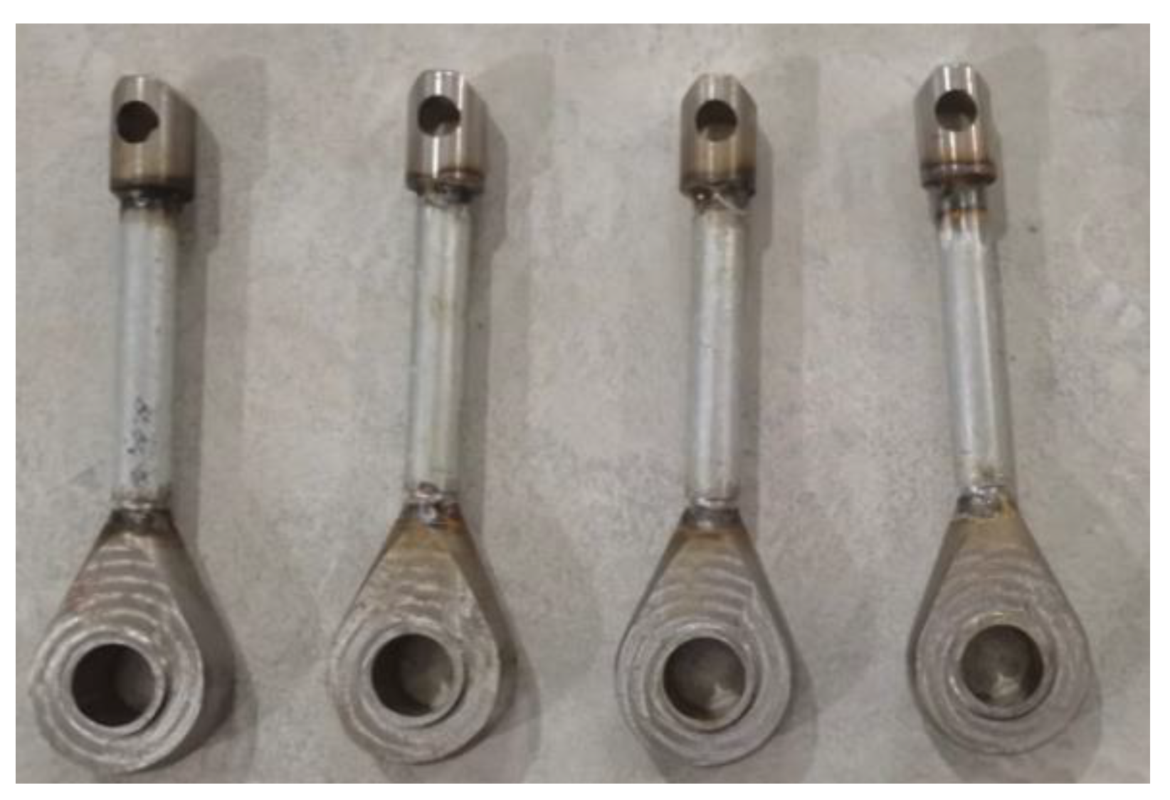
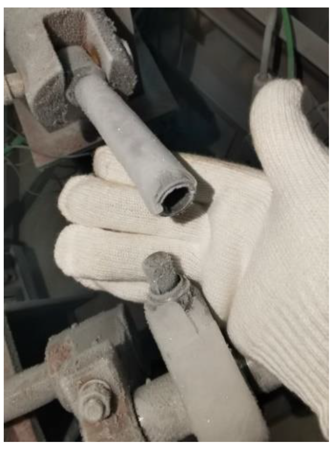
According to the above experimental steps, when the test was terminated, the rudder bar specimens were checked for fatigue fracture location, and all of the fractures were found at the guide tie rod step, which was consistent with the results of the previous static calculation of the rudder bar mechanism. In the actual test process, the stress value at the guide rod step is larger, and after a long period of cyclic loading, due to the low temperature and multiple ice-cover effects, cracks will first occur at this location. With time, the cracks continue to expand eventually leading to fatigue fracture. The rudder bar specimen fracture at -40 °C is shown in
Figure 11.
The rudder bar specimen cyclic load number under ice cover is shown in
Table 1. The table shows that when the temperature is subzero, the number of loads is reduced by an order of magnitude. At -40 °C the number of cycles is as low as 500 fewer, which is three percent of the number of cycles at room temperature. This also indicates that the low-temperature load of the specimen dramatically changes.
The underwater vehicle rudder mechanism ice cover is mainly affected by the rudder itself, the environment and other factors, of which the environmental factors have a greater impact on the rudder surface ice cover, so the main consideration is the impact of the Arctic low-temperature environment on the rudder surface ice cover. Rudder surface ice mainly comes from two aspects: one is that when the underwater vehicle floats, the part of the rudder emerging out of the seawater in the low-temperature environment undergoes instant water freezing and ice formation; the other is that the cold seawater droplets hitting the rudder surface instantly freeze and become ice. Therefore, the water droplet collection rate will affect the ice cover on the rudder surface to a certain extent [
22].
The surface of the rudder components is cylindrical, and according to ISO standards, the collection rate of water droplets that freeze in the air for cylindrical structures η
1 can be given by formula (1) [
23]:
Here d is the diameter of the water droplet, D is the diameter of the cylindrical structure, ρw is the water content in the air, μ is the air viscosity, and Re is the Reynolds number.
The energy conservation equation and mass conservation equation for the growth process of ice cover on the rudder bar surface are shown below:
In formulas (2) and (3), is the air density, is the surface water film thickness of the component, is the specific heat capacity of the rudder, is the thermal equilibrium temperature, is the surface liquid film flow velocity, is the airflow temperature in the flow field domain, is the airflow velocity, is the liquid water content in the air, is the water droplet collection coefficient, is the impact velocity of the droplet hitting the surface of the component, is the evaporation mass of liquid water, is the anti-icing heat flux, and is the icing mass.
After analyzing the relationship between the number of cyclic loads and the test environment, and observing the fracture characteristics, the following test conclusions are drawn:
(1) The number of cyclic loads under each temperature band is relatively discrete, which is in line with the discrete characteristics of the fatigue test data.
(2) At 20 °C and 0 °C, there is no ice cover on the rudder bar specimen; at -20 °C, the surface of the rudder bar specimen exhibits an ice shell with a thickness of 0.6 mm. At -40 °C, at the moment when the rudder bar specimen is removed from the icy water, the thickness of the ice cover on the surface of the rudder bar specimen reaches more than 1 mm, the moisture in the air continuously gathers on the rudder bar specimen in the experimental process, and the final thickness of the ice cover reaches 1.6 mm. The existence of ice cover affects the temperature distribution of the structural surface, resulting in the dispersion characteristics of structural fatigue test data. The presence of ice will affect the temperature distribution on the surface of the structure, resulting in a lower temperature on the surface of the structure, which reduces the strength of the steel. Ice cover increases the loading on the structure, resulting in additional loads being applied to the structure [
24]. This results in the structure being subjected to greater loads, which may cause mechanical effects such as bending, shearing, and twisting of the structure, thus affecting the performance of the structure.
(3) The relationship between the number of cyclic loads of the rudder bar specimen and the simulated Arctic environment is as follows: when the temperature is 20 °C and 0 °C, the number of cyclic loads does not change much; when the temperature decreases to -20 °C, the number of cyclic loads decreases to 53.7% of that at room temperature. When the temperature decreases to -40 °C, the number of cyclic loads shows a precipitous drop, a decrease of 96.7% compared with that at room temperature.
(4) The reason for the precipitous drop in the number of cyclic loads at -40 °C can be categorized into two points: first, the low temperature significantly increases the sensitivity of the rudder bar specimen to grooves and cracks; second, the ice coating on the surface of the rudder bar specimen affects it, leading to a significant reduction in its fatigue life.
The accuracy and reliability of the model were verified by comparing its results with experimental data.
5. Conclusions
In this paper, the fatigue life of an underwater vehicle rudder rod mechanism under a polar low-temperature environment is studied, and the following results are obtained through experiments and simulation analysis:
1. In the polar low-temperature environment, the material properties of the rudder rod mechanism decrease, which leads to the shortening of its fatigue life, especially when the temperature is reduced to -40 °C, and the fatigue performance of the rudder rod specimen is reduced by 96.7%.
2. Cyclic loading is one of the main factors leading to fatigue cracking of the rudder bar mechanism. In a low-temperature environment, the mechanical properties of the material decrease, making the effect of cyclic loading on the mechanism more significant.
3. Ice-covered conditions have a significant effect on the fatigue life of rudder rod specimens, and the reasons can be summarized as follows: increased structural loads, reduced strength, weakened stability, the formation of local support, corrosion, and hydrogen embrittlement aggravation.
In summary, we conducted fatigue simulation and experiments on the rudder mechanism of underwater vehicles, achieving the goal of conducting fatigue life analysis on the structure at low temperatures. In the future, we will further select materials and structures suitable for the polar low-temperature environment to improve the fatigue life of the rudder rod mechanism.
