1. Introduction
Flotation presents one of the major and commonly applied methods for the beneficiation of non-ferrous and rare metal ores. Unfortunately, this method is not sufficiently effective for small particle flotation because of the losses of considerable amounts of valuable metals in the form of fine ore particles smaller than 15 µm into tailings. With the depletion of rich deposits and a noticeable shift to developing poor finely disseminated ores, the challenge of fine particle flotation assumes greater importance [
1]. It is already well established, theoretically [
2,
3,
4,
5], as well as experimentally [
6,
7,
8,
9], that the flotation rate is fundamentally dependent on the efficiency of particle capture by a rising bubble and, in the first approximation, proportional to the value
, where
and
are particles and bubbles sizes respectively. Thus, it follows that the efficient flotation of particles smaller than 15 µm requires the application of bubbles smaller than 200 µm. Unfortunately, the bubbles produced in most conventional flotation cells are coarser, approximately by the order of magnitude [
10]. Several methods of small generating have been developed and are available [
11], yet their implementation in the industry is accompanied by serious issues. In particular, the method discussed in [
12,
13] involves pulp saturation with microbubbles by passing the pulp through the electrolyzer with insoluble electrodes. And though the laboratory tests provided sufficiently positive results of the flotation of fine particles smaller than 15 µm, implementation of this method in practice raises concerns because of the formation of large amounts of oxygen and hydrogen gas mixture. Currently, two types of flotation machines are used, in which relatively small microbubbles (MB) are generated by the method of dispersing air and the cavitation effect due to the impact of a pulp jet on the water/air interface (Jameson Cell) [
14] or alternatively through the collision with an obstruction inside the pulp, as well as passing the pulp and air mixture through venturi tubes (IMHOFLOT Cell) [
15]. Unfortunately, the mentioned methods would not ensure the generation of sufficient quantities of bubbles less than 100 µm in size, which is critical for the flotation of ultrafine mineral particles.
It has already been established [
16] that in conventional mechanical flotation machines, the process of flotation by coarse bubbles could be enhanced by applying a relatively small number of fine bubbles, which in this case will essentially be as flotation carriers. A theoretical explanation for this effect was given in [
17]. This mode of fine particle flotation is now termed combined microflotation (CMF), as it is based on the use of fine and coarse bubbles.
The high effectiveness of the CMF of ultrafine particles has been proven by multiple laboratory tests with artificial and natural mineral mixtures [
18,
19,
20]. In all test runs, microbubbles were generated by mechanically dispersing air in a frother solution. Depending on the concentration and activity of the frother, the air-in-water microdispersion thus produced contained up to 60 vol. % microbubbles of the dimensions in the range 10 to 100 µm. The dispersion obtained by this mode could be directed through a pipe to any spot in the flotation chamber where the most intense mixing occurs.
It was initially assumed that the greater the dose of MB per unit mass of floated particles is, the more pronounced the effect of flotation enhancement should be. However, further theoretical and experimental findings have demonstrated that the optimal dose of MB is significantly dependent on the density and size of particles, and if the dosage of MB is not set correctly, the application of MB may have a negative impact on the flotation process.
The purpose of this study is to define how the dosage of MB affects the effectiveness of CMF and also establish critical factors that influence this optimal dosage value.
2. Theory
2.1. Mechanisms of particle transfer into the froth layer
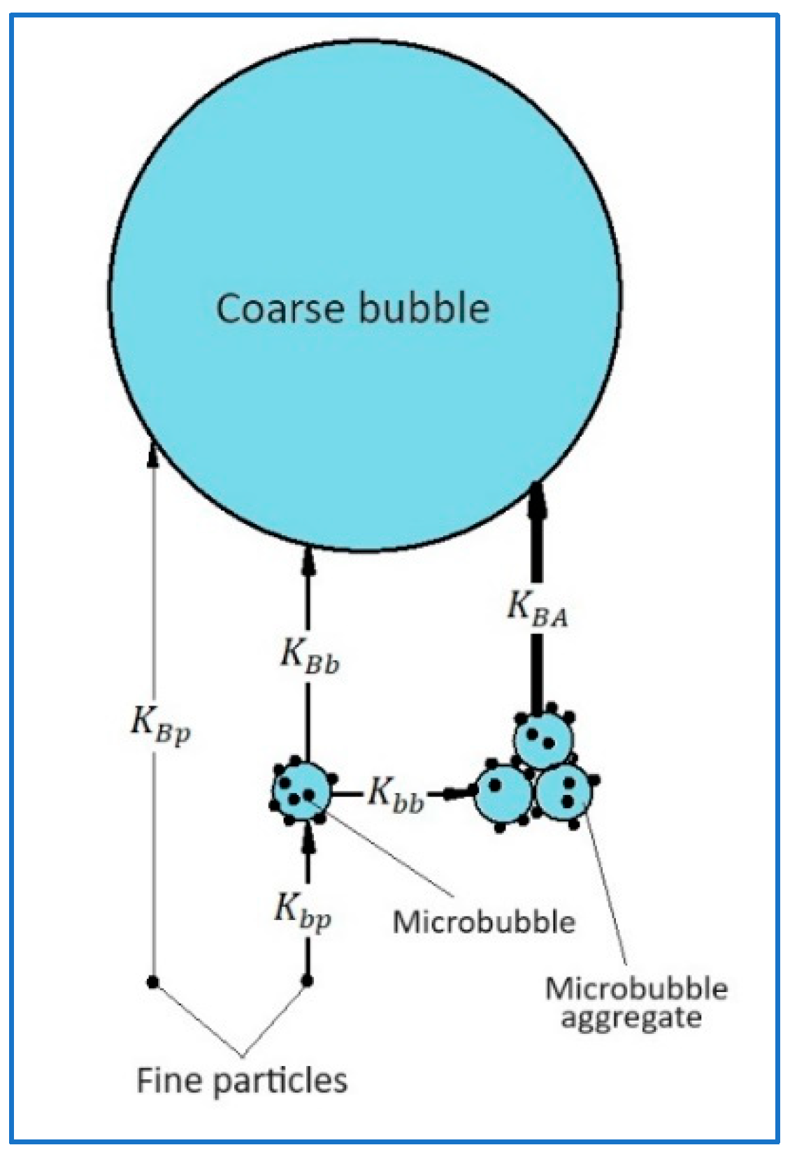
Figure 1 shows graphic layouts for various mechanisms of particle transfer onto the surface of a coarse bubble (CB) and into the froth layer.
Mechanism I comprises the direct deposition of a particle on the surface of a rising CB under the effects of surface and hydrodynamic forces. The rate constant of this process is determined by the relation [
7]
where
is the superficial air velocity induced by CB flow,
is their diameter,
denotes the capture efficiency of a particle by bubbles that is determined by the ratio [
6]
where
is particle size,
is the coefficient which reflects the effects of surface and hydrodynamic forces involved in the interaction of a particle with the surface of a bubble. Thus, from formulas (1) and (2) it follows that
Mechanism II of the particle transfer to the CB surface comprises the sequence of two events: first is the deposition of a particle on the surface of an MB, and second is the attachment of MB on the CB surface. Since the sedimentation of both MB and small particles occurs very slowly, the settlement of particles on the MB surface will mostly occur due to the non-uniformity of the hydrodynamic field in a flotation cell. In this case, the rate constant of the process can be estimated by the formula [
21]
where
is the diameter of the SB,
is the average shear rate of the medium,
is the volume concentration of MB in pulp,
is the probability of a particle attachment to the surface of the bubble when they collide in a simple shear field. As it was previously shown [
22], in the case where
, the function
takes the form
where
is the parameter dependent on the nature of the surface forces of interaction between the particle and the MB. From formulas (4) and (5) it follows that the rate constant of the first stage is
When it comes to the second stage, then by the analogy with the above process of direct deposition of particles on CB surface, we obtain the ratio for the rate constant shown below
where
is the probability of MB attachment on the CB surface under the action of the surface forces. As the rate of the chain of successive events equals the rate of the slowest one, the rate of the second mechanism of particle deposition onto CB is determined by the smaller of the two rate constants
and
.
Mechanism III of the particle transfer to CB comprises the sequence of three events: 1 presents the deposition of a particle on the MB surface; 2 involves combining MB into aggregates, and 3 is actually the deposition of MB aggregates on the surface of the CB or alternatively directly into the froth layer. According to the Smoluchowski equation modified with the account of aggregates porosity [
23], which describes the process of particles aggregation in the simple shear field, we obtain
where
is the dimension of MB aggregates;
is their porosity;
is the probability of MB to form an aggregate at their collision in the simple shear flow. This probability depends on the ratio of the surface and hydrodynamic forces. Hence the rate constant of the second stage can be estimated by the formula
In terms of the third stage, then by the analogy with the immediate deposition of MB on the CB, the process rate constant can be expressed as
where
is the probability of MB aggregates to deposit on CB’s surface, which is determined by the ratio of the surface and hydrodynamic forces. In brief, the rate of mechanism III shall be determined by the smallest of the rate constants
,
and
. Since either of the parameters
,
,
,
,
is smaller than unity, hence in formulas (3, 6, 7, 9 and 10) we assume these parameters as equal to unity, and this will allow us to estimate the maximum values of the rate constants of sub-processes involved in the particle transfer into the froth layer. For illustration purposes,
Table 1 shows the particle transfer rate constants for the above three mechanisms, which are calculated for the most probable parameters of the flotation process. Presented data show that the rates of particle transfer into the froth layer vary depending on the mechanism, and the rate of mechanism II is by an order of magnitude, and mechanism III is by two orders of magnitude faster compared to that by mechanism I, and the particle deposition onto MB occurs practically instantly. The value
= 0.1 mm is selected on the reason that it is close to the size limit of particle floatability [
24]. At the same time, we should consider that very large aggregates loaded with light particles (for example, coal or quartz particles) can be independently entrained into the froth layer, as observed in [
18,
20].
2.2. Optimal microbubble dosage
The essential precondition for the functioning of the third, most effective mechanism of particle transfer onto the CB surface is the formation of aggregates from MB loaded with particles. Since hydrophobic particles act like bridges, which, similarly to flocculants, bind MB into aggregates, it is necessary that the volumetric dose of MB per unit weight of floated particles is optimal. If the MB dose is very low, then their surface will be practically completely occupied by particles, and hence, they cannot form aggregates. But if the MB dose is quite high, there could be too few particles, so the probability of aggregate formation due to bridges of hydrophobic particles could be very low. Consequently, there must be some optimal dose of MB, which is dependent on the size and on the density of particles, as well as on the size of the MB.
The practice of using flocculants shows [
25], that the optimal MB dose should be set so as to ensure the coverage of half of the MB surface by particles. Let’s assume that the number concentration of MB in the pulp is
, and the number of floated particles is
. Then the volumetric dose of SB per the unit weight of particles
can be expressed by the formula
где
is the particles density. The share of MB surface that could be taken by particles can be estimated using the formula
where
is the coefficient of MB surface coverage. Combining the formulas (11) and (12), we arrive at
Assuming that in (13)
, we obtain the expression for the optimal MB dose
As it follows from the formula (14), the optimal dosage of MB increases with the decrease of particle dimension and their density. Thus, for example, the optimal MB dose for quartz will be four times higher than that for particles of chalcocite of the same dimensions.
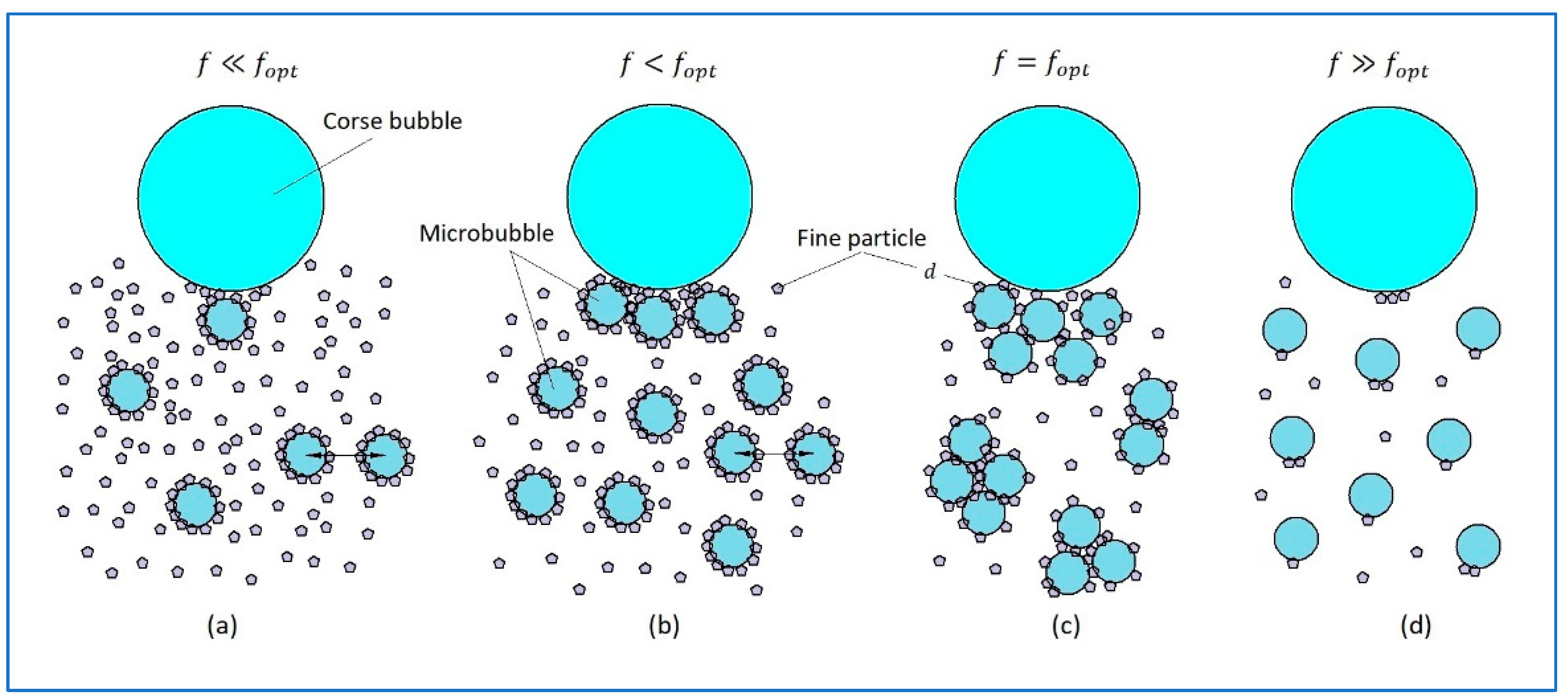
Obviously, particle transfer mechanisms onto CB shall depend on the MB dosage. For illustration purposes,
Figure 2a shows the diagram for the case when the small bubble dose is significantly below the optimal one. In this case, all small bubbles will be completely covered by particles very fast, and the particles will block the aggregation, and the transfer of particles on CB will occur mostly by mechanism I. In the opposite case, shown in
Figure 2b, where the MB dose is slightly below the optimal, the greater share of particles will attach to the bubble surface, thus blocking the aggregation, and the particle transfer will occur mostly by mechanism II. If the MB dose is optimal, then as shown in
Figure 2c, small bubbles can form aggregates, and the particle transfer will happen primarily by mechanism III. Finally, if the MB dose is significantly higher than the optimal, then as it is shown in
Figure 2d, the coverage of their surface will be minor, and the probability of their aggregation or attachment onto the CB surface will be low.
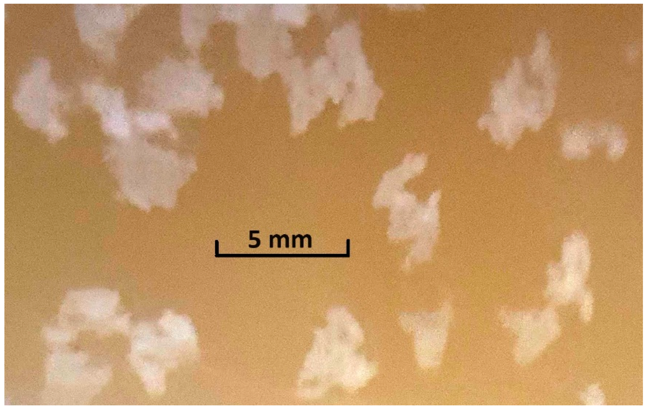
Of course, at some doses of MF, the transfer of particles onto the CB can occur simultaneously by two or three of the mentioned mechanisms. Besides, in the flotation of light particles, so large aggregates can form that they can rise into the frother layer without assistance from CB. As an example,
Figure 3 shows.
3. Experimental
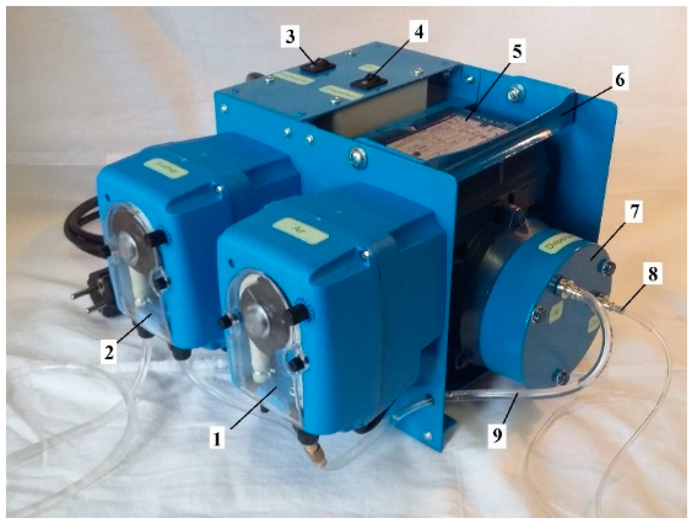
For the purposes of validating the above-mentioned theoretical considerations, a series of laboratory studies were conducted, including the tests of the effectiveness of CMF on the copper ore tailings at the concentrators ATALAYA MINING (Spain) and CHAARAT KAPAN (Armenia). In these tests, the air-in-water microdispersion was produced and fed into the flotation cell by the MBGen-0.012 generator provided by TURBOFLOTSERVICE Company (Ukraine), shown in
Figure 4 below. This unit has the capacity to generate up to 12 L/h of microdispersion, containing up to 58 vol.% of microbubbles of 10-100 µm in size. Therefore, the required dosage of SM could be fed into the cell in 5-15 s.
3.1. Atalaya Mining
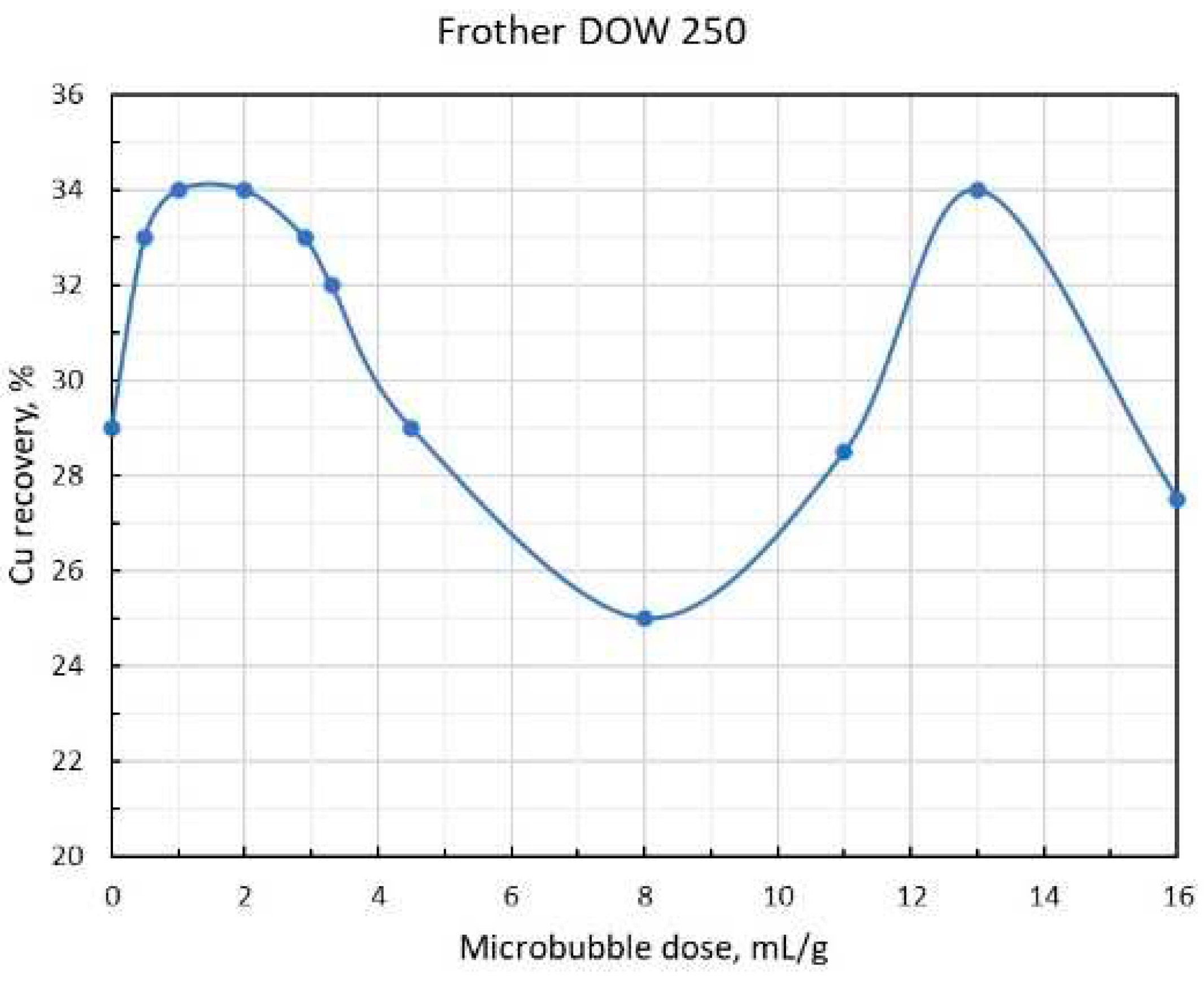
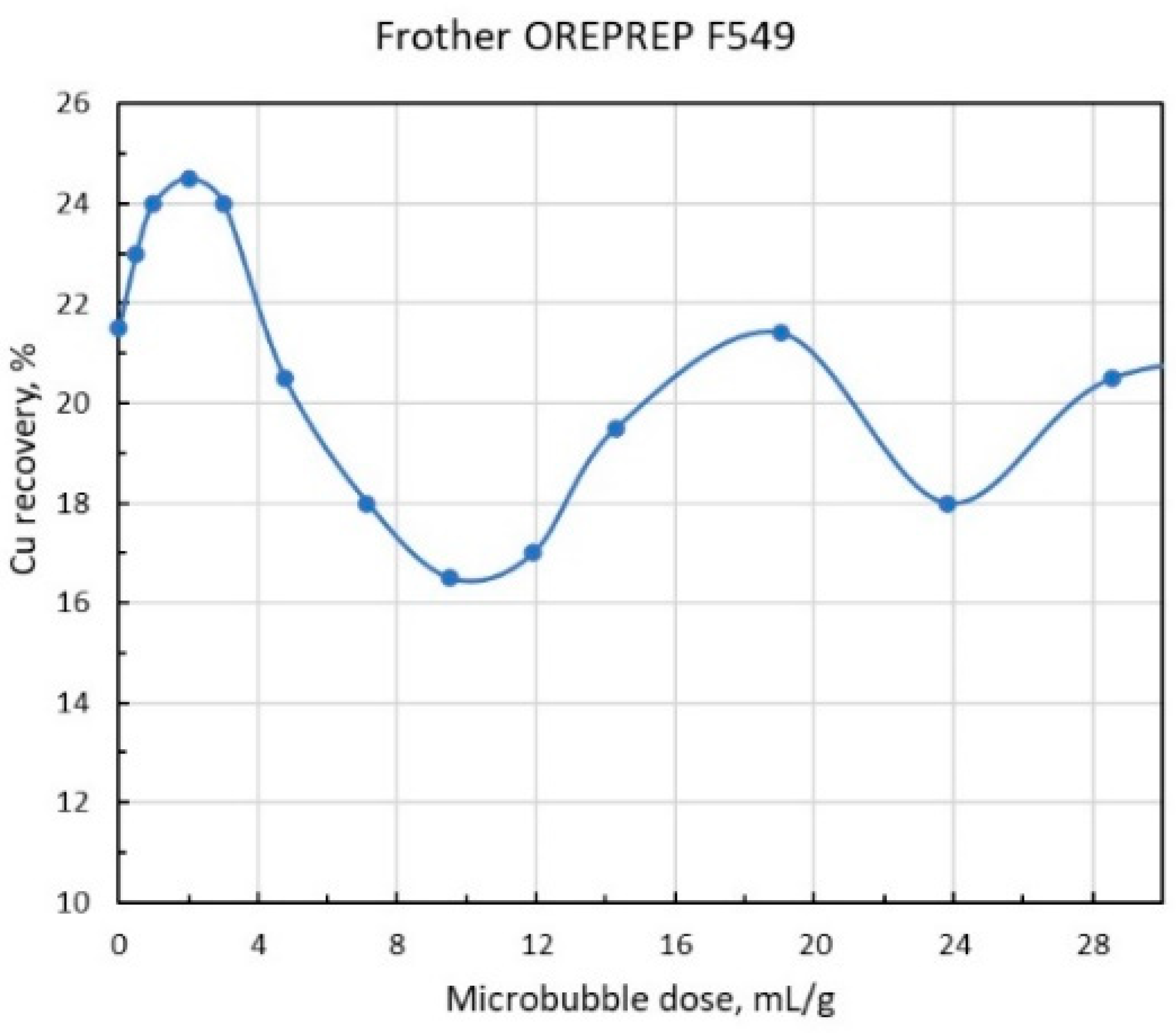
Flotation tests were conducted in a 2.7 L laboratory cell with the automatic collection of froth concentrate in 5-second froth scraping intervals. The test run specifications are: total flotation time -10 min; impeller speed - 900 rpm; airflow rate - 3 L/min. The frother used in the tests were DOWFROTH 250 and OREPREP F549. The solids concentration in the pulp varied in the range of 327 – 423 g/L; the copper content in the feed was in the range of 0.064 – 0.078 %; the chalcopyrite concentration in the pulp was 0.21-0.33 g/L; frother concentration in pulp was 5.1 mg/L. The introduction of microbubbles in the flotation cell was arranged via a narrow silicon tube before the start of flotation.
As shown in
Figure 5 and 6, copper recovery dependencies on the MB dose per one mass unit of chalcopyrite reach the extreme pattern with maximums at low and high doses. As the optimum dose
, as it follows from the graphs, is about 1.75 mL/g, then substituting this value in the formula (14), and the value for the chalcopyrite density
= 4.3, we obtain
= 3.8. The presence of a sufficiently deep minimum between the two maxima of copper recovery values can be explained by the fact that when the MB dose is getting much higher than the optimal one, the process of formation of large aggregates accelerates, and the aggregates become are so large that, as mentioned above, they cannot be retained on the CB any longer, yet they are not coarse enough to overcome the convective flows inside the flotation cell independently and rise into the frother layer. As
Figure 4 shows, a further increase in MB dose promotes the formation of aggregates that are so large themselves that they start to rise like CB, and, in fact, this factor explains the presence of a sufficiently high maximum in the recovery in the MB dose range that is by order of magnitude higher than the optimal one
. Finally, the decrease in recovery after the second maximum can be attributed to the fact that at gigantic MB doses, the number of particles on them decreases so much that the probability of MB aggregates formation, or MB attachment onto the CB, drops practically to zero.
3.2. Chaarat Kapan
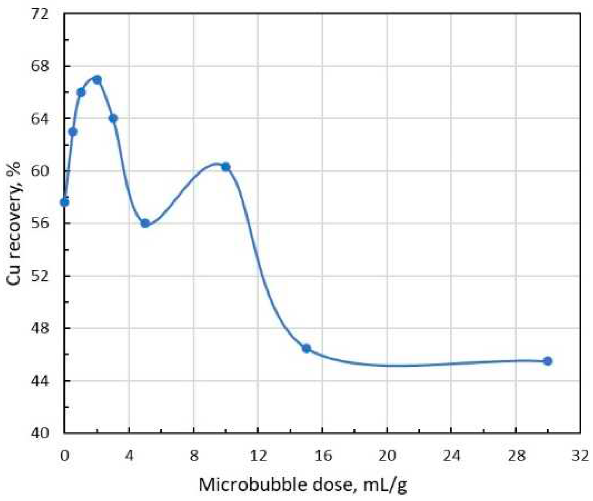
Rougher copper tailings (i.e., copper scavenger feed) flotation tests were conducted in a 2.7 L laboratory flotation cell for 10 minutes at an impeller speed of approx. 900 rpm and airflow rate 0.12 L/min. Flomin F-650 frother was used in all tests for MB production in the MBGen-0.012 generator. The solids concentration in the pulp was 234-247 g/L; the copper content in the form of chalcopyrite particles was 0.086-0.094%; the chalcopyrite concentration in the pulp was 0.20-0.3 g/L; frother concentration in pulp was 3.1 mg/L. The introduction of microbubbles in the flotation cell was arranged via a narrow silicon tube before the start of flotation.
Figure 7 shows the dependence of copper recovery on SB dose. In this test, two maxima were observed in the range of small and large SB doses, while when the doses increased above 12 mL/g, a significant blocking in chalcopyrite flotation occurred.
4. Conclusions
Combined microflotation of small particles involves three main mechanisms for particles transfer onto the coarse bubble surface and their further transport into the frother layer: 1-direct deposition of particles onto the surface of coarse bubbles; 2- deposition of particles onto the surface of microbubbles, which in their turn deposit on coarse bubbles; 3- deposition of particles onto the surface of microbubbles that combine into aggregates, and the aggregates, in their turn, deposit on coarse bubbles or independently rise into the froth layer.
There are two doses of microbubbles for the ranges of their small and large values.
In the range of small values, the optimal dose of microbubbles can be estimated by the formula , where is the microbubbles dimension, and are the particles size and density respectively.
Funding
This research received external funding from TMR Technology Inc.
Data Availability Statement
The data presented in this study are available on request from the corresponding author. The data are not publicly available due to the privacy of the patients who assisted in the research.
Acknowledgments
The author expresses his thanks and appreciation to TMR Technology Inc. in the person of President Alken Kuanbay for the arrangements and financing of the tests at the Atalaya Mining (Spain) and Chaarat Kapan (Armenia) concentrators and also wishes to thank the employees of these companies for their technical assistance in the test runs and chemical examination of flotation products. Special thanks to the TURBOFLOTSERVICE company (Ukraine, Kyiv) that provided the MBGen-0.012 air-in-water microdispersion generator.
Conflicts of Interest
The author declares no conflict of interest.
Abbreviations
| MB |
Microbubble |
| CB |
Coarse bubble |
| CMF |
Combined microflotation |
References
- Farrokhpay, S.; Filippov, L.; Fornasiero, D. Flotation of Fine Particles: A Review. Mineral Processing and Extractive Metallurgy Review 2020. [Google Scholar] [CrossRef]
- Sutherland, K.L. Physical Chemistry of Flotation. XI. Kinetics of the Flotation Process. The Journal of Physical and Colloid Chemistry 1948, 52, 394–425. [Google Scholar] [CrossRef] [PubMed]
- Gaudin, A.M. Flotation, 2nd ed.; McGraw-Hill: New York, 1957. [Google Scholar]
- Anfruns, J.F.; Kitchener, J.A. The rate of capture of small particles in flotation. Trans. Instit. Mining Metall. Section C 1977, 86, C9. [Google Scholar]
- Derjaguin, В.V.; Dukhin, S.S.; Rulev, N.N. Kinetic theory of flotation of small particles. In Surface and Colloid Science; Plenum Press: N.Y. - London, 1984; pp. 71–113. [Google Scholar]
- Tomlinson, H.S.; Fleming, M.G. Flotation Rate Studies. Mineral Processing: 6-th International Congress (Cannes, June 1963): Pergamon Press, London: 1965, pp. 562–573.
- Flint, L.R.; Howarth, W.J. Collision efficiency of small particles with spherical air bubbles. Chem. Eng. Sci. 1971, 26, 1155–1168. [Google Scholar] [CrossRef]
- Reay, D.; Ratcliff, G. A. Removal of fine particles from water by dispersed air flotation- effects of bubble size and particle size on collection efficiency. Canadian Journal of Chemical Engineering 1973, 53, 178–185. [Google Scholar] [CrossRef]
- Reay, D.; Ratcliff, G. A. Effects of Bubble Size and Particle Size of Collection Efficiency. Canadian Journal of Chemical Engineering 1975, 53, 481–486. [Google Scholar] [CrossRef]
- Sawyerr, F.; Deglon, D.A.; O’Connor, C.T. Prediction of bubble size distribution in mechanical flotation cells. The Journal of The South African Institute of Mining and Metallurgy 1998, July/August, 179–185.
- Jung, M.U.; Kim, Y.C.; Bournival, G.; Ata, S. Industrial application of microbubble generation methods for recovering fine particles through froth flotation: A review of the state-of-the-art and perspectives. Advances in Colloid and Interface Science 2023, 103047. [Google Scholar] [CrossRef] [PubMed]
- Glembotsky, V.A.; Mamakov, A.A.; Romanov, A.M.; Nenno, V.E. Selective separation of fine mineral slimes using method of electric flotation. In Proceedings of the 11th International Mineral Processing Congress, Cagliari; 1975; pp. 561–582. [Google Scholar]
- Bhaskar Raju, G.; Khangaonkar, P. R. Electro-flotation of chalcopyrite fines. International Journal of Mineral Processing 1982, 9, 133–143. [Google Scholar] [CrossRef]
- Harbort, G.; De Bono, S.; Carr, D.; Lawson, V. Jameson Cell fundamentals – a revised perspective. Minerals Engineering 2003, 16(11), 1091–1101. [Google Scholar] [CrossRef]
- Imhof, R.; Fletcher, M.; Vathavooran, A.; Singh, A. Application of Imhoflot G-Cell centrifugal flotation technology. The journal of The Southern African Institute of Mining and Metallurgy 2007, 107, 623–631. [Google Scholar]
- lembotsky, V.A.; Klassen, V.I. Flotation, Nedra, Moskau, 1973.
- Rulyov, N.N. Combined microflotation of fine minerals: Theory and Experiment, Mineral Processing and Extractive Metallurgy (Trans. Inst. Min. Metall. C) 2016, 125, Issue 2, 81-85. [CrossRef]
- Rulyov, N.N.; Filippov, L.O.; Kravchenko, O.V. Combined Microflotation of Glass Beads. Colloids and Surfaces A: Physicochemical and Engineering Aspects 2020, 598, 5 August, 124810 . [CrossRef]
- Rulyov, N.N.; Filippov, L.O.; Sadovskyi, D.Y.; Lukianova, V.V. Reverse combined microflotation of fine magnetite from the mixture with glass beads. Minerals, 2020; 10. [Google Scholar] [CrossRef]
- Rulyov, N.; Sadovskiy, D.; Rulyova, N.; Filippov, L. Column flotation of fine glass beads enhanced by their prior heteroaggregation with microbubbles. Colloids and Surfaces A: Physicochemical and Engineering Aspects 2021, 617, 126398. [Google Scholar] [CrossRef]
- Van de Ven, T.G.M.; Masson, S.G. The microrheology of colloidal dispersions. VII. Orthokinetic doublet formation of spheres. Colloid Polym. Sci. 1977, 255, 468–479. [Google Scholar] [CrossRef]
- Adler, Р.М. Heterocoagulation in shear flow. J. Colloid Interface Sci. 1981; 83, 106–115. [Google Scholar] [CrossRef]
- Rulyov, N.N.; Dontsova, T.A.; Nebesnova, T.V. The pair binding energy of particles and size flocs, which are formed in the turbulent flow. Khimiya i Tekhnologtya Vody 2005, 27, 1–17. [Google Scholar]
- Ralston, J.; Fornasiero, D.; Grano, S.; Duan, J.; AkroydInt, T. Reducing uncertainty in mineral flotation-flotation rate constant prediction for particles in an operating plant ore. J. Miner. Process 2007, 84, 89–98. [Google Scholar] [CrossRef]
- Gregory, J. Polymer adsorption and flocculation in sheared suspensions. Colloids & Surface 1988, 31, 231245. [Google Scholar]
|
Disclaimer/Publisher’s Note: The statements, opinions and data contained in all publications are solely those of the individual author(s) and contributor(s) and not of MDPI and/or the editor(s). MDPI and/or the editor(s) disclaim responsibility for any injury to people or property resulting from any ideas, methods, instructions or products referred to in the content. |
© 2023 by the authors. Licensee MDPI, Basel, Switzerland. This article is an open access article distributed under the terms and conditions of the Creative Commons Attribution (CC BY) license (http://creativecommons.org/licenses/by/4.0/).
