Preprint
Article

Modification of Direct Control System Based on Three-Level Autonomous Inverter NPC with Random Frequency Commutation

Altmetrics

Downloads

89

Views

37

Comments

0

This version is not peer-reviewed

Submitted:

25 December 2023

Posted:

26 December 2023

You are already at the latest version

Alerts
Abstract
Adjustable frequency converters are widely used in modern automated asynchronous drives due to their high efficiency and high responsiveness control strategies. Control algorithms for frequency converters are divided into two main groups: constant frequency commutation and random frequency commutation. Research results on various commutation frequencies, conducted using Matlab/Simulink software, show that the use of random frequency commutation provides better efficiency by significantly reducing the amplitude of harmonic oscillations at different frequencies, with a reduction in switching losses in transistors. Currently, a converter with random frequency commutation is being researched and applied in the direct torque control system. The traditional direct control system, based on a two-level inverter, is widely used due to its simplicity and ease of implementation. However, this method results in the output current of the two-level converter, supplied to the motor stator, having many harmonic distortions, leading to strong torque fluctuations regardless of the rotation speed and ultimately causing additional losses in the stator windings and reducing the motor's lifespan. To enhance the efficiency of automated asynchronous drives, this article presents an algorithm for a direct control system based on a three-level NPC inverter using a PI speed regulator. The proposed algorithm's research is validated in the Matlab/Simulink environment. The research results show that in the absence of harmonic filtering, the stator current harmonic distortion coefficient is approximately 11%, and torque fluctuations are less than 5% of the resistive torque. The fluctuations between the two capacitors remain almost unchanged throughout the entire process.
Keywords: 
Subject: Engineering  -   Control and Systems Engineering

1. Introduction

One of the key aspects in the field of energy conservation in the mining industry is the transition from unregulated to regulated electric drives, which has been investigated in [1,2,3]. This transition brings significant benefits, including energy savings and improvement in production processes [4,5].
To enhance energy efficiency, many industrial enterprises and companies in practice are adopting variable frequency drive technology for asynchronous electric drives. The use of frequency converters allows for substantial reduction in electricity expenses, improvement in operational economic efficiency, increased equipment reliability, extension of motor and mechanism lifespan, enhanced productivity, and implementation of intelligent electric drive control systems [6,7,8].
Harmonic distortions, undesirable changes in electric current, can create serious problems for automated asynchronous drives [9]. Harmonic distortions lead to interference and disturbances in the direct current line, resulting in reduced efficiency and sometimes causing serious issues such as data transmission failures, overheating, and equipment damage [10].
Electric drive devices, such as motors and frequency converters, often act as sources of harmonics, increasing the complexity and difficulties in maintaining stable system performance. These effects not only shorten equipment lifespan but also increase costs for maintenance and repairs [11].
To address this issue, methods such as the use of active filters like SAPF [12] and MPPT [13] are applied. These filters can eliminate unwanted harmonic distortions by introducing compensating current into the system. Research also focuses on developing a multi-level frequency converter structure to optimize performance and reduce harmonics in medium and high-power applications, such as the use of a five-level autonomous inverter with 53 = 125 output voltages, contributing to improved energy conversion efficiency [14,15]. However, applying a five-level autonomous inverter faces difficulties due to its relatively large and complex number of algorithms.
Additionally, research involving artificial neural network (ANN) algorithms [16], fuzzy logic controls [17,18], ant colony optimization algorithm [19] is actively underway. However, their practical implementation in industry also faces some challenges due to complex control structures and algorithms. Some other studies focus on algorithm modifications, such as combining direct torque control (DTC) with space vector modulation of sinusoidal pulse width modulation (SVPWM) [20,21,22], or applying control systems with model reference adaptive system (MRAS) [23], P-MRAS [24]. Other research related to direct torque control of motors based on three-level converters is presented in the following works [25,26]. From these studies, it is evident that the implementation of a three-level autonomous inverter with a neutral point clamped (NPC) in a frequency converter represents significant progress in the field of energy conservation, aimed at optimizing performance and reducing harmonics in the alternating current line [27].
Direct torque control (DTC) based on a three-level autonomous NPC inverter is an advanced method in the field of electric drives, providing high performance and accuracy. Since DTC is a control method that does not require the use of a model for the entire system, it significantly reduces calculation time [28]. The application of DTC and a three-level autonomous NPC inverter ensures efficient and flexible motor control, minimizing the impact of harmonics, and optimizing electric drive performance [29].
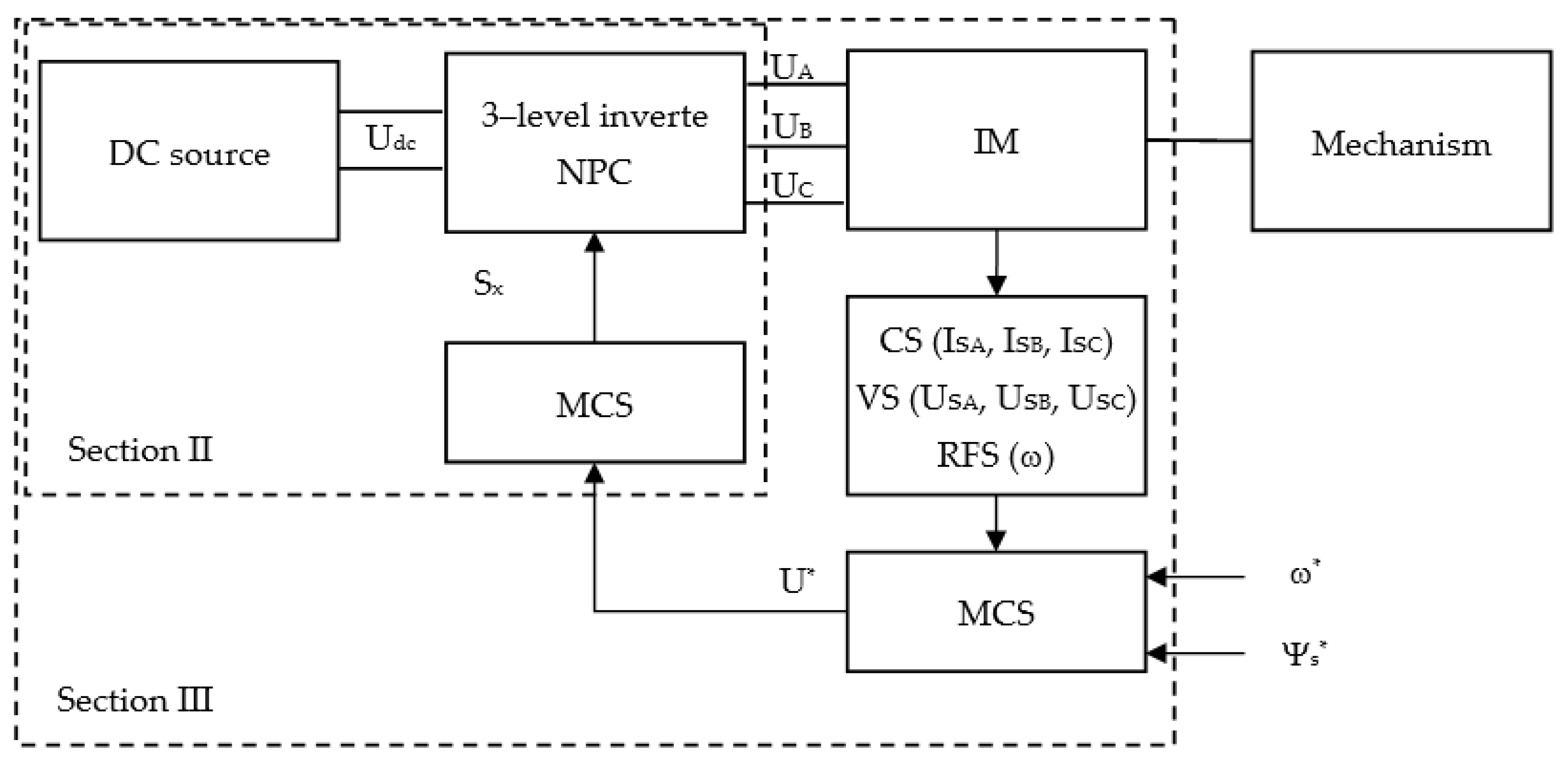
Based on the analysis of literature on the structure and control algorithms of asynchronous electric drives, a structural diagram of an automated asynchronous drive based on a three-level NPC inverter is proposed, as depicted in Figure 1 [30,31,32]. This system consists of a direct current source (battery), a three-level autonomous NPC inverter, a drive motor (IM), voltage sensors (VS), current sensors (CS), rotational frequency sensors (RFS), a motor control system (MCS), which, depending on the motor’s state and the required stator flux (Ψs*) and rotational frequency (ω*), generates a specified voltage on the three-level inverter (Ux), and a modulation control system (MСS), which, depending on the specified voltage, creates commutation functions for the inverter (Sx).
In this article, the authors evaluated a novel solution for controlling an asynchronous motor based on a three-level frequency converter with a neutral point clamped NPC, using the proposed voltage switching table. Simulation results were developed in the Matlab/Simulink environment to demonstrate the feasibility of the proposed table. The study confirmed the success of the proposed table in improving system performance. This opens up broad prospects for application in industrial systems and represents a significant contribution to the development of asynchronous motor control systems.
The article is organized as follows: Section 2 discusses the possibility of optimizing the modulation control system of the three-level NPC inverter by studying the impact of different commutation frequencies on the operation of the automated asynchronous drive. Section 3 discusses the possibility of modifying the direct torque control algorithm of the asynchronous motor based on the three-level NPC inverter with the proposed voltage switching table and its various tests. Simulation results using Matlab/Simulink software and conclusions are drawn in Section 4.

2. Optimization of the Modulation Control System Based on the Three-Level Autonomous NPC Inverter

Currently, modulation control systems with constant switching frequency, such as pulse width modulation (PWM), PWM with predistortion, and SVPWM, are a common method for controlling power inverters [33,34,35]. They maintain a constant switching frequency of the inverter keys for a certain period, regardless of changes in the output voltage. Despite numerous advantages, modulation control systems with constant switching frequency also have some drawbacks discussed in works, such as:
  • Since the switching frequency remains constant, this system may face difficulties in regulating the output voltage and current, especially during sudden load changes. This may require more complex control algorithms to maintain stable system characteristics.
  • Constant switching frequency can cause resonance phenomena with some elements in the system, such as filters and loads, leading to increased harmonic levels or current distortion.
  • High-frequency harmonics can arise in the systems, creating problems with electromagnetic compatibility and causing electromagnetic interference.
To address this issue, a pulse width modulation system with functional switching frequency modification has been introduced. The main principle of operation of this system is to control the duration of the inverter key control pulses.
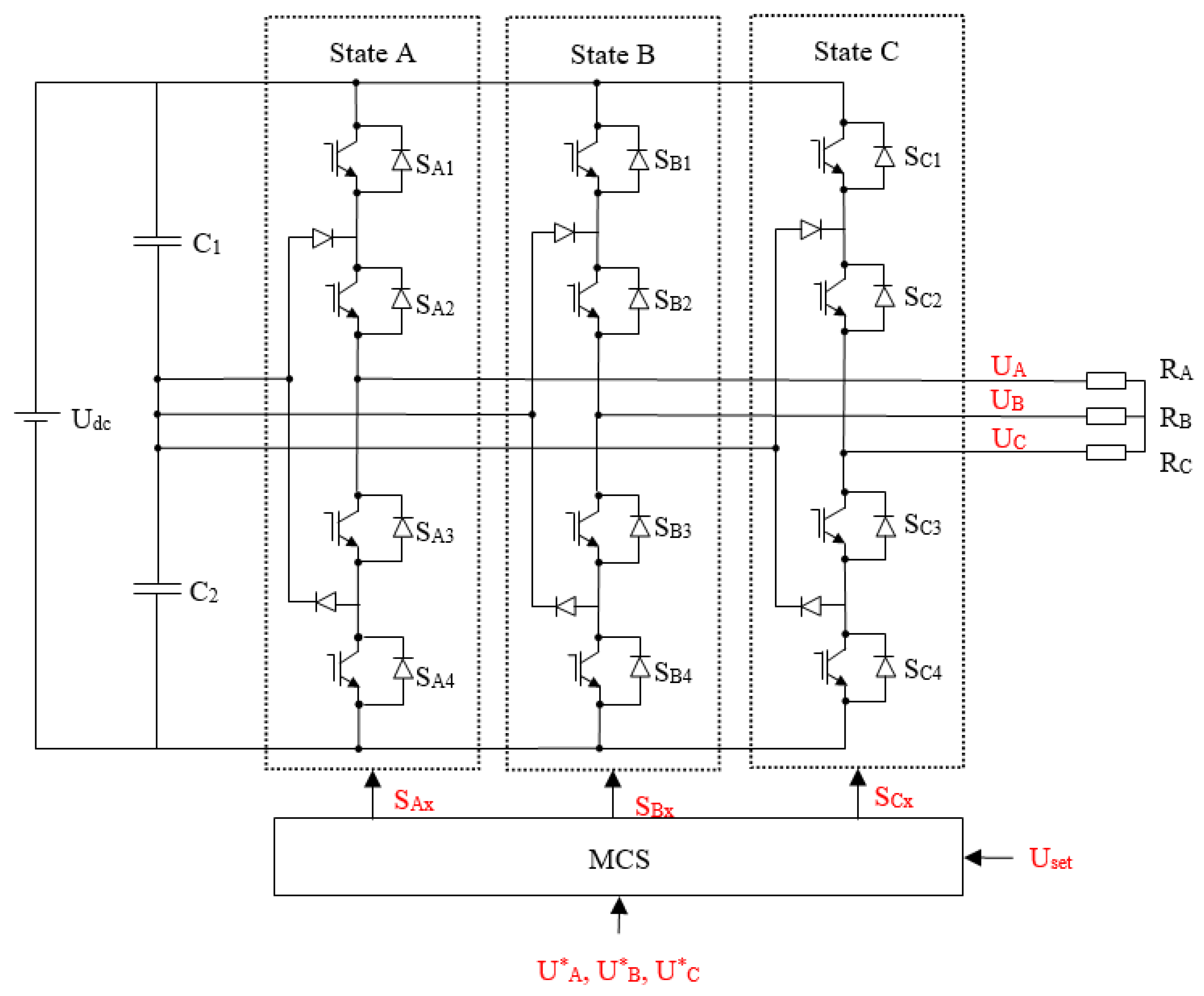
To analyze the impact of applying pulse width modulation systems with constant and functionally modified switching frequency on the stator currents, an equivalent diagram of an automated asynchronous drive based on a three-level NPC inverter was constructed (Figure 2).
This diagram consists of an equivalent load (RA = RB = RC =1 Ω), which is connected to the three-level NPC inverter through a constant voltage source Udc = 100 V. Voltage and current waveforms were generated with different frequency settings throughout the period without the use of a choke, including:
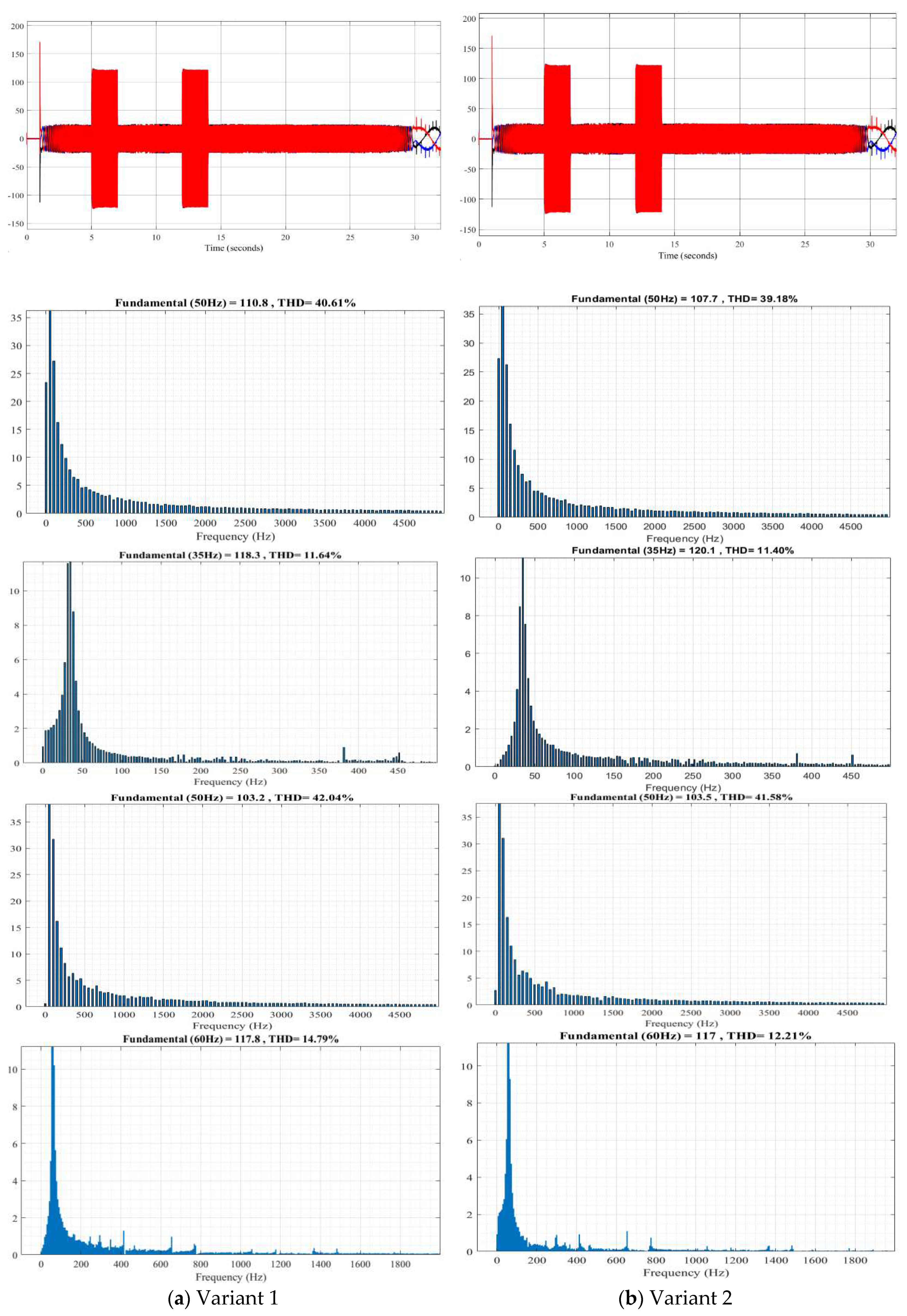
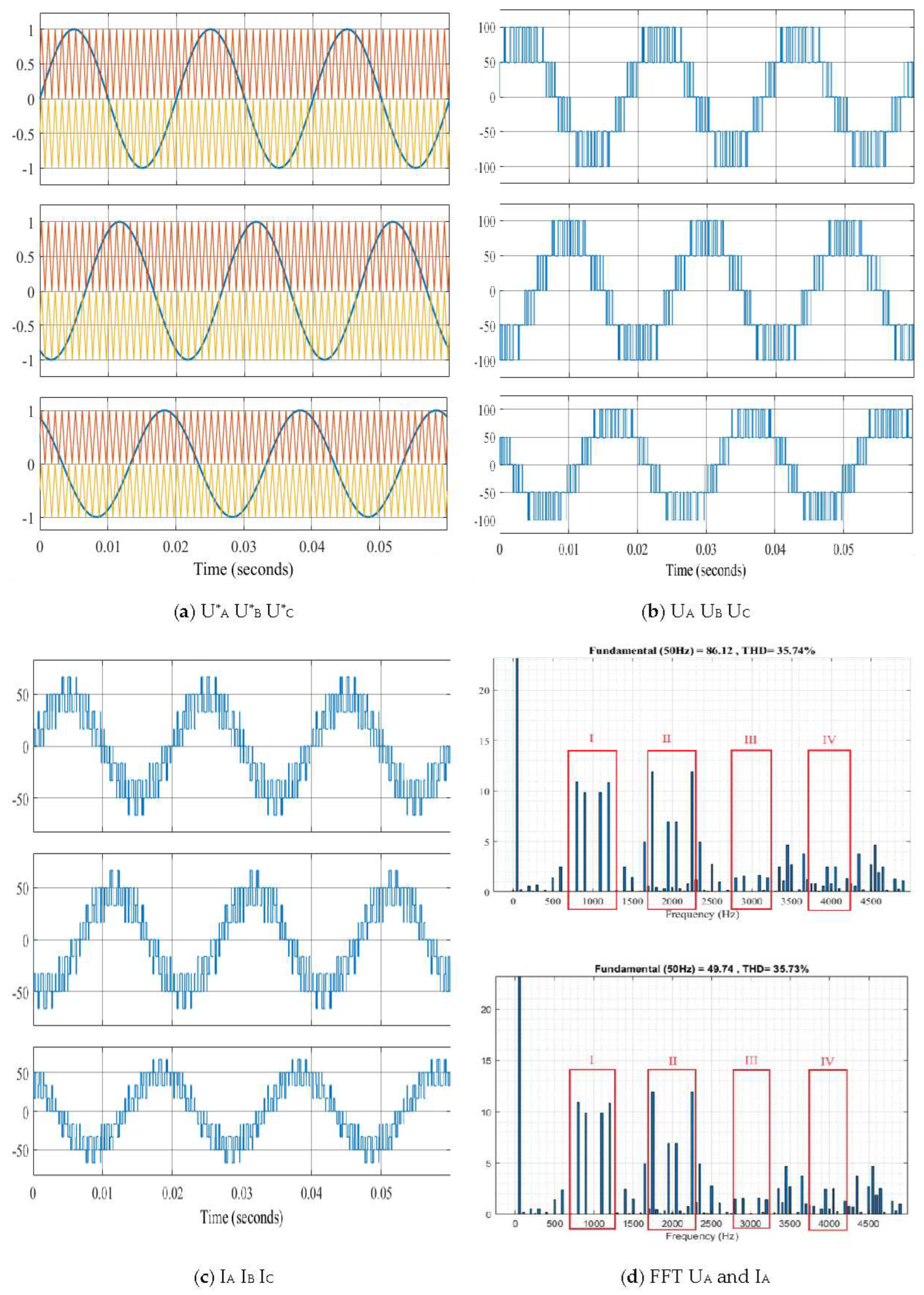
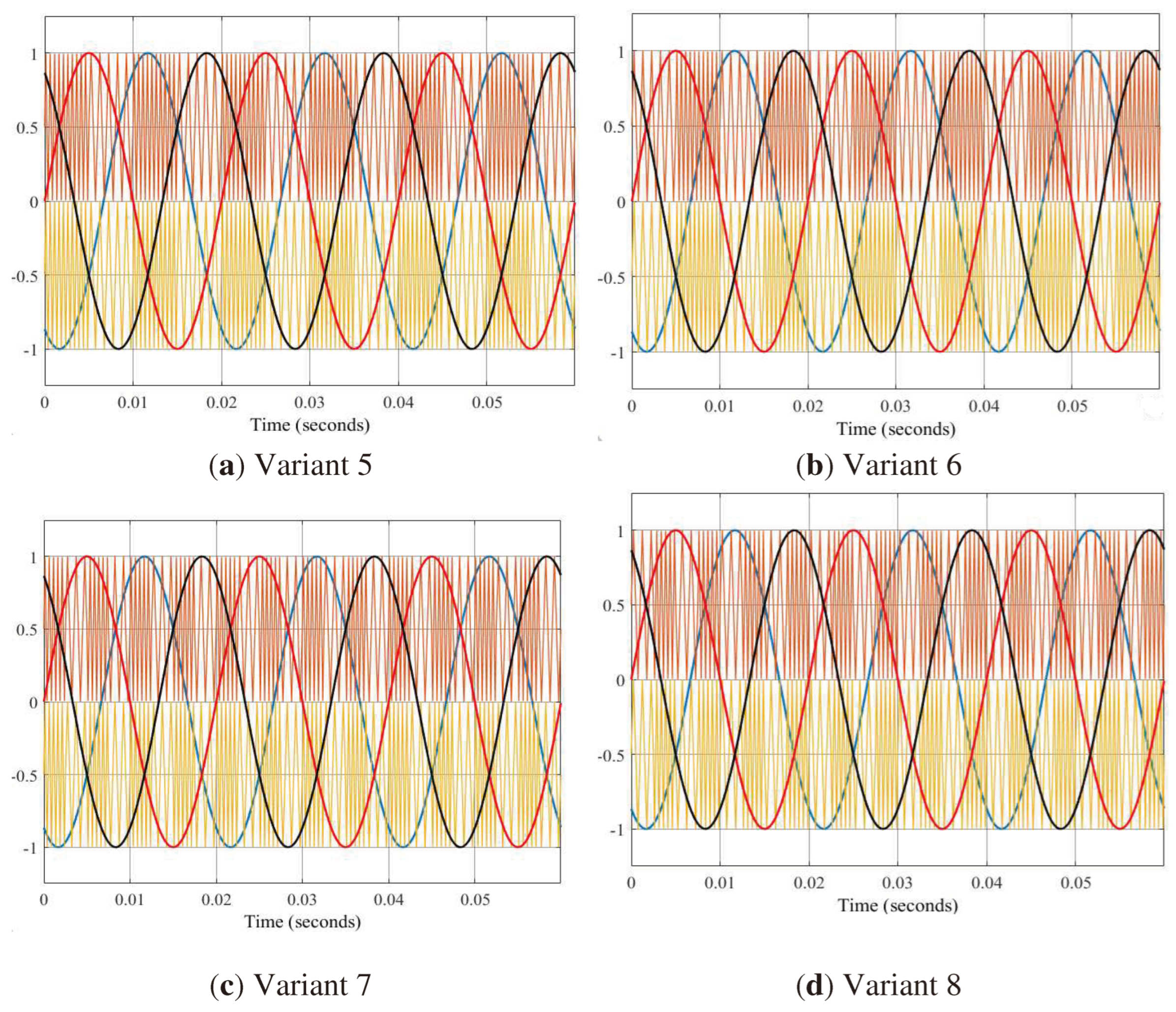
  • Variant 1: at a constant switching frequency f = 1000 Hz (Figure 3);
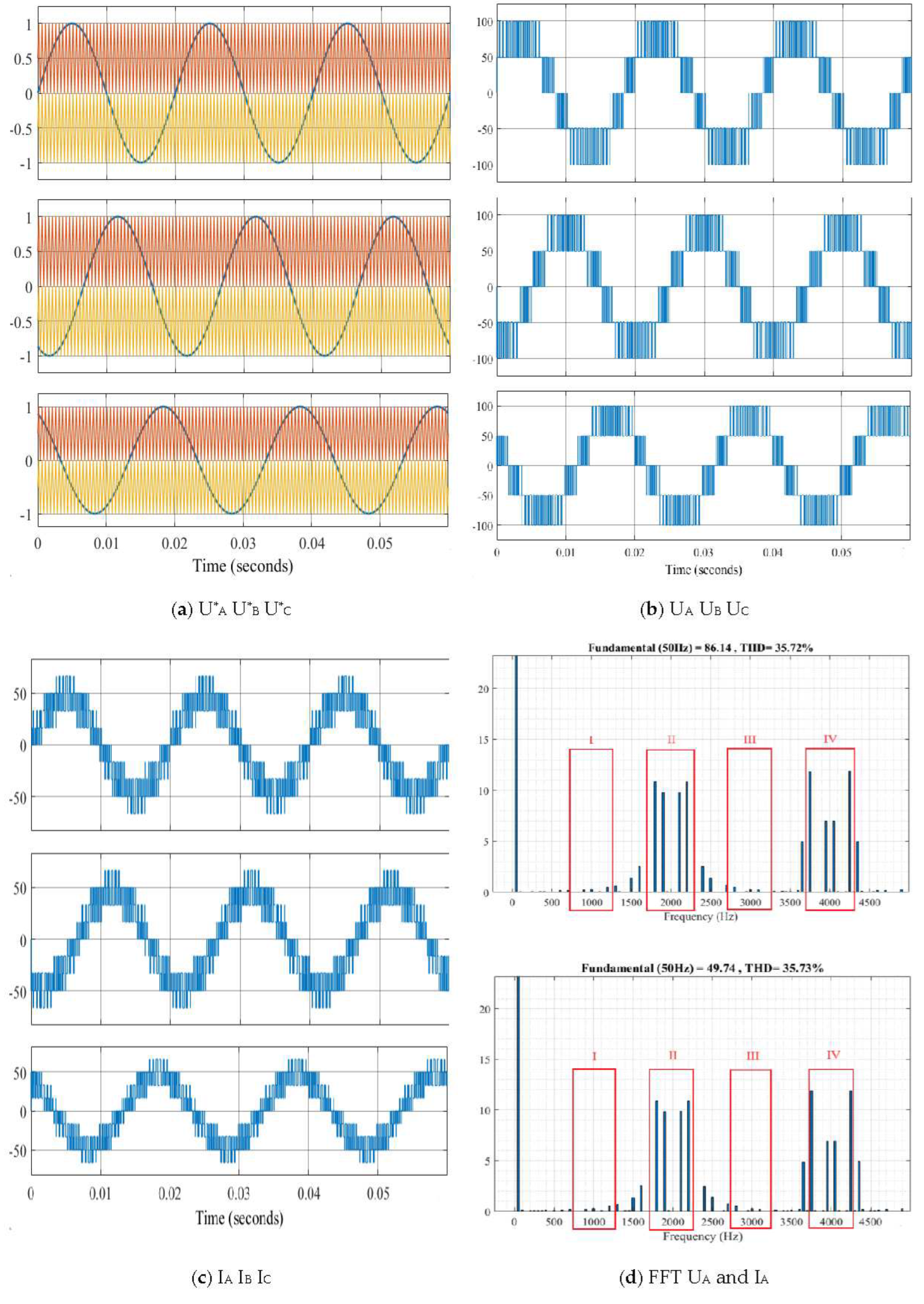
  • Variant 2: at a constant switching frequency f = 2000 Hz (Figure 4);
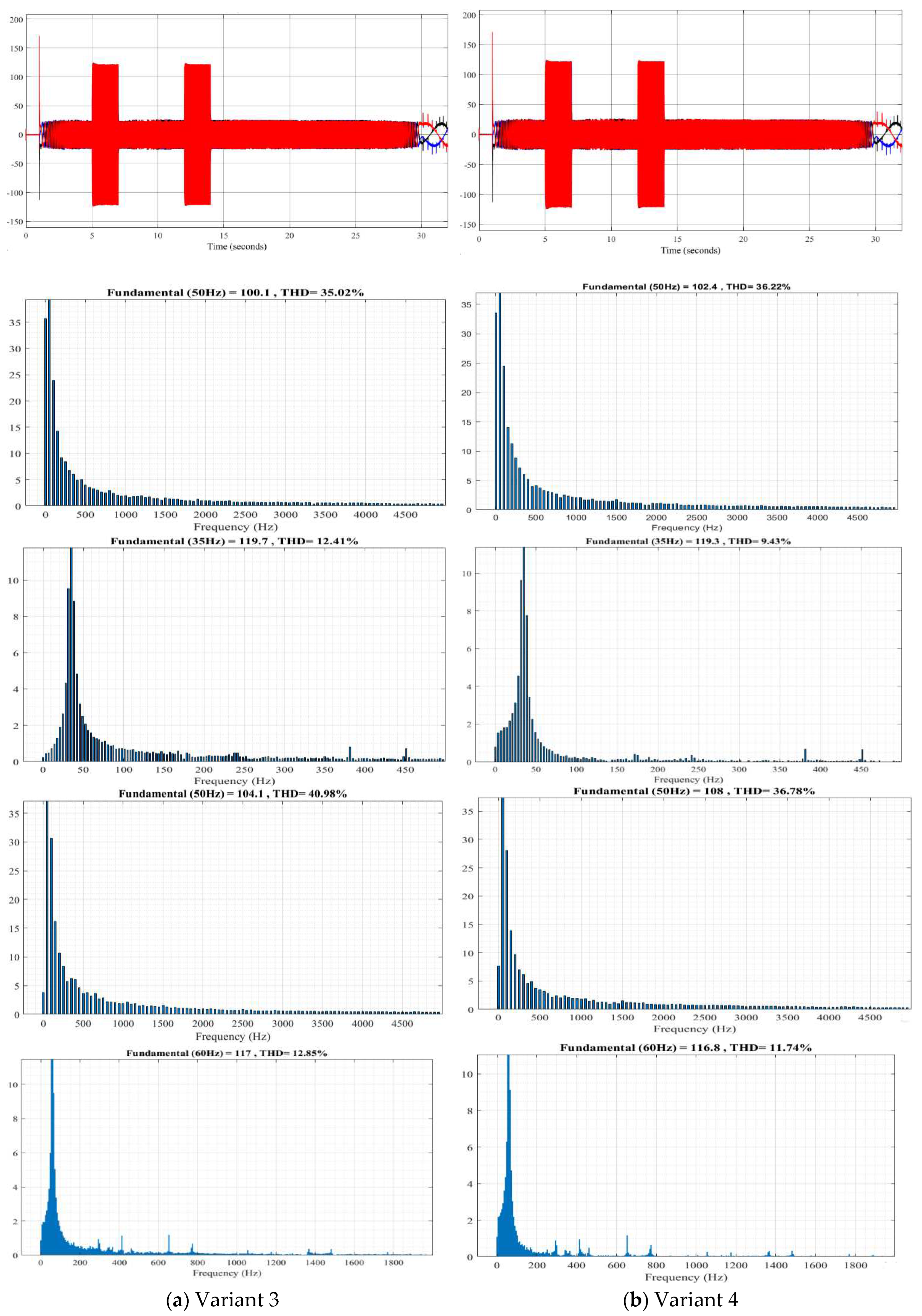
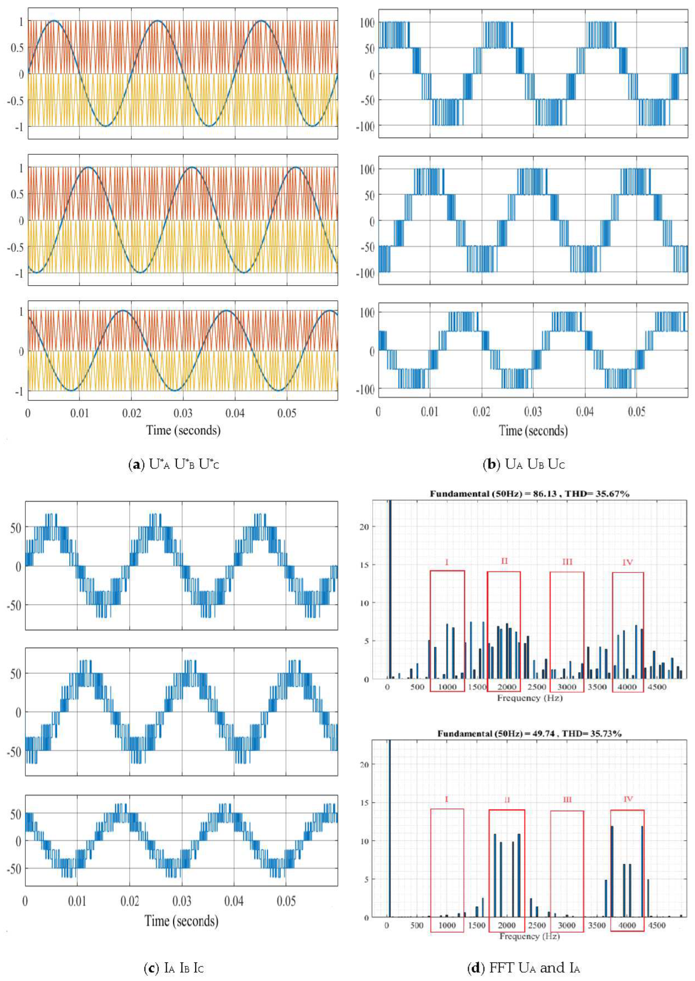
  • Variant 3: with a combination of switching frequencies f = 2000 and f = 1000 Hz (Figure 5);
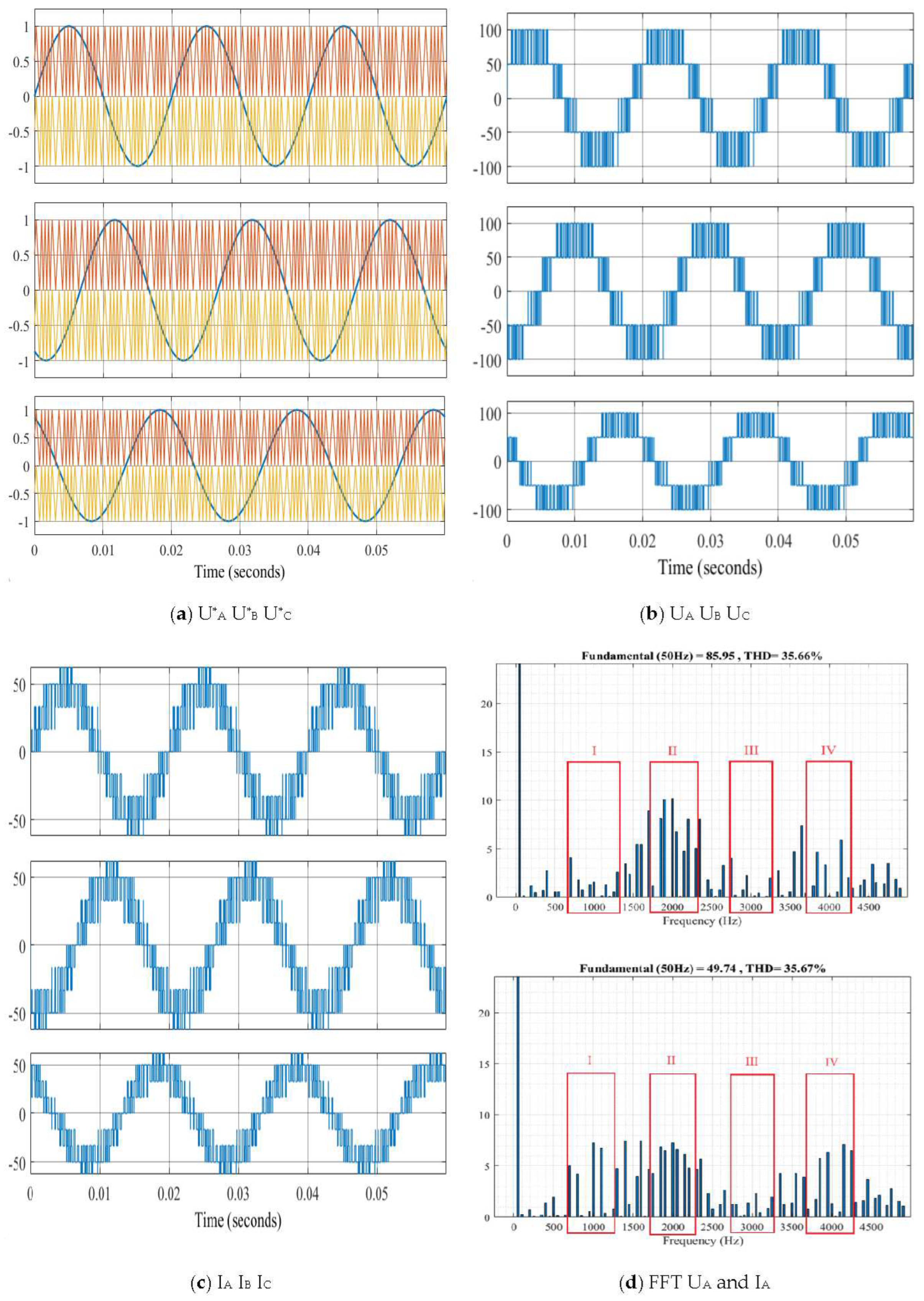
  • Variant 4: with a combination of switching frequencies f = 1000 and f = 2000 Hz (Figure 6).
In addition to the proposed variants, the authors suggest other options for investigating random commutation frequencies, as depicted in Figure 7. The research results are presented in Table 1.
To investigate the impact of random commutation frequencies on the alternating current line, an inductance L=1 mH is introduced into the specified system, and research is conducted for eight different scenarios. The research results are presented in Table 2.
The maximum amplitudes of voltage and current distortion without the L filter and with the L filter installed are presented in Table 3 and Table 4.
From Table 1, the following conclusions can be drawn: the application of random commutation frequencies maintains the amplitudes of the output voltage (UA) at approximately 86.1 and the current (IA) at approximately 49.7.
From Table 2, the following conclusions can be made: the application of inductance minimizes current distortions in the alternating current line (from approximately 35.7% to 3-4%), while reducing the current amplitude from approximately 49.7 to about 47.5.
From Table 3 and Table 4, the following conclusions can be drawn: the maximum amplitudes of voltage and current distortion without a choke or with a choke have low values in Zones I and II, and moderate values in Zones III and IV (Variant 5 reduces the maximum amplitudes of voltage and current distortion by almost 2 times).
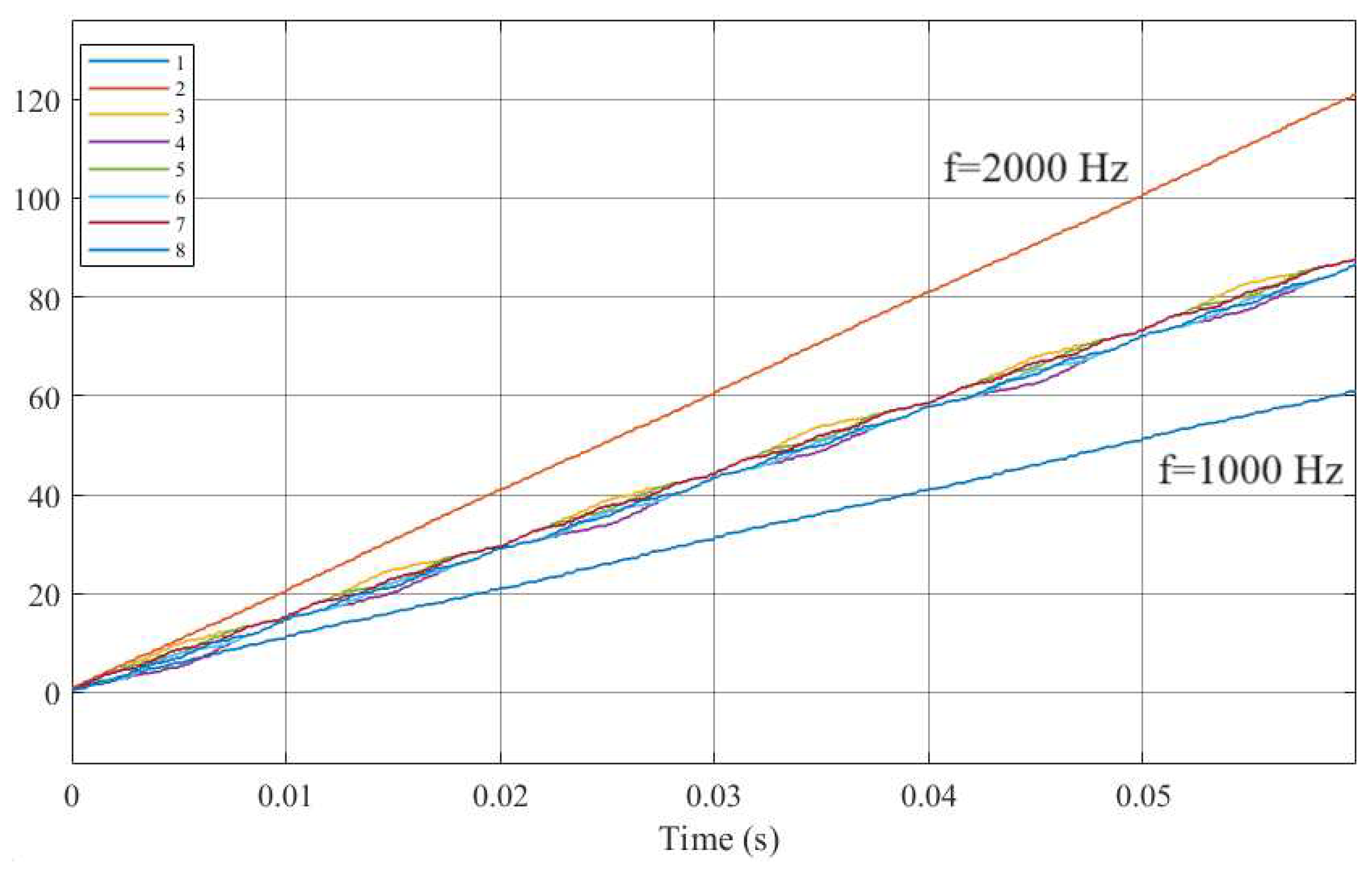
From Figure 8, the following conclusion can be made: random commutation frequency has an average value in terms of the number of transistor switching’s in the inverter (approximately 80 switching’s in 0.06 seconds), which helps reduce switching losses in the transistors.
The main drawbacks when using random commutation frequency are that altered commutation frequencies can cause electromagnetic interference, requiring additional components for suppression.
In conclusion, the application of random commutation frequency has many advantages, including reducing the switching frequency of transistors and the amplitudes of voltage and current distortion, with or without a choke. Currently, random commutation frequency is being researched and implemented in direct torque control systems.

3. Modification of the direct control system based on the three-level autonomous NPC inverter

Limitations when studying the three-level autonomous NPC inverter in the scheme of connecting an asynchronous motor to a constant voltage source without a motor choke:
  • At any given time during the inverter operation, a set of two switches is turned on.
  • The formation of output voltages should follow a periodic law.
  • Pairs in one column should be in an anti-phase.
  • The inverter state changes through the switching of a pair of switches.
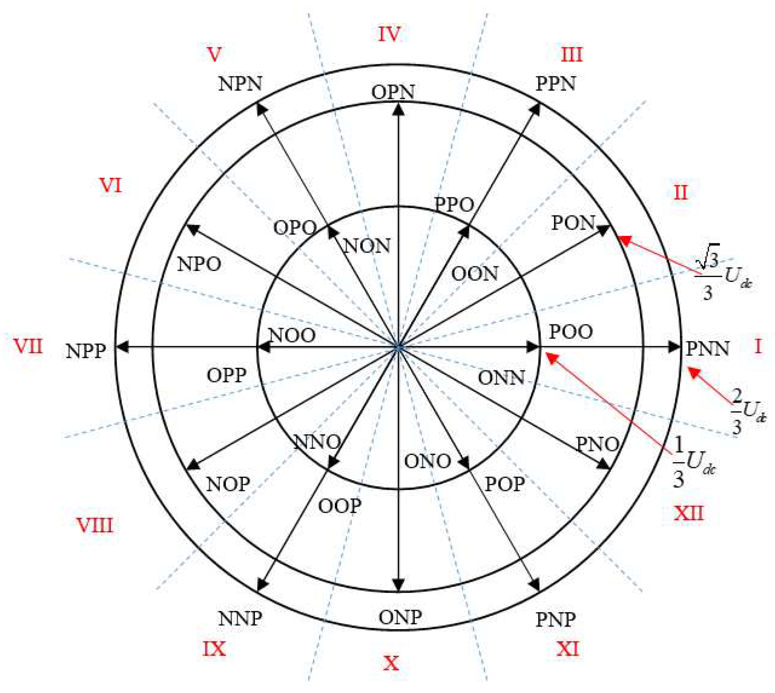
From Table 5, it can be concluded that the voltage vectors of the three-level inverter include four main groups:
Zero vectors: V0 000 V7 PPP V26 NNN
Short vectors: V1 POO, V8 ONN, V2 PPO, V9 OON, V3 OPO, V10 NON, V4 OPP, V11 NOO, V5 OOP, V12 NNO, V6 POP, V13 ONO.
Long vectors: V14 PNN, V17 NPP, V15 PPN, V18 NNP, V16 NPN, V19 PNP.
Medium vectors: V20 PON, V23 NOP, V21 OPN, V24 ONP, V22 NPO, V25 PNO.
The distribution of these vectors is clearly presented in Figure 11. The estimated values of the torque and stator flux are compared with their corresponding required values. The results of this comparison serve as input data for creating the control law.
The space of voltage vectors of the three-level NPC inverter is divided into 12 sectors (Figure 8), each comprising 30°. To implement direct torque control for a motor connected to a three-level NPC inverter, an optimized commutation table needs to be developed, taking into account the inverter’s state capabilities.
The construction of the table depends on the choice of the applied voltage vector to increase or decrease the value of the electromagnetic torque and stator flux. For a three-level inverter, it is necessary to consider the change in the torque when designing the control table, which is determined by the formula:
M = 3 2 k s k r σ L 0 Ψ s Ψ r sin θ
where: k s = L m L s ; k r = L m L r ; σ = 1 k s k r – constants value;
Ψs и Ψr – stator and rotor flux;
θ – angle between the stator and rotor flux.
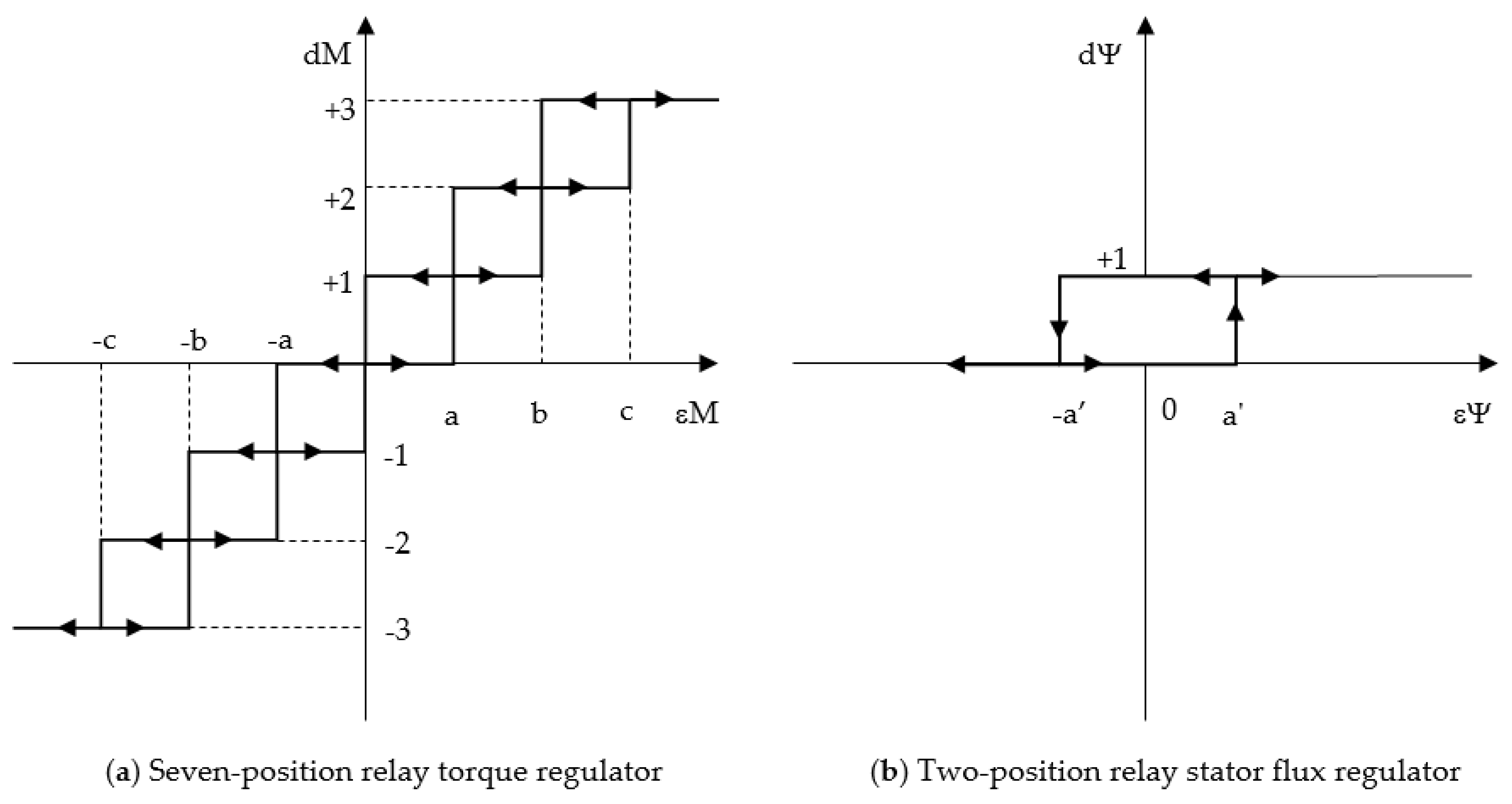
In Direct Torque Control (DTC) with a two-level inverter, a three-position relay controller checks the torque state (±1, 0), and for the stator flux linkage, a two-position relay controller is applied (1,0). Usually, it is recommended to use the highest error state values (positive or negative) for large voltage vectors to achieve rapid changes in torque. The smallest values (positive or negative) are recommended for small voltage vectors to achieve slow changes in torque.
From the formula above, it can be seen that the rate of change of torque depends on the choice of the voltage vector to change the stator flux linkage and the angle between the stator and rotor flux linkages. To account for the fact that the stator and rotor flux linkages of an asynchronous motor should remain at a nominal level, the impact of the voltage vector on the change in torque should be evaluated based on the influence of the voltage vector on the angle between the stator and rotor flux linkages.
When considering that the stator flux linkage vector tends to approach the voltage vector, two positions can be highlighted:
If the voltage vector leads to an increase in the angle between the stator and rotor flux linkage vector (1 > sin(θ) > 0), shifting the stator and rotor flux linkage vectors, this vector leads to an increase in torque. The rate of increase depends on the voltage vector’s value and the angle between the stator and rotor flux linkages.
If the voltage vector leads to a decrease in the angle between the stator and rotor flux linkage vector (0 > sin(θ) > -1), bringing the stator and rotor flux linkage vectors closer, this vector leads to a decrease in torque. The rate of increase depends on the voltage vector’s value and the angle between the stator and rotor flux linkages.
Figure 9. Voltage vector space of three-level NPC inverter.
Preprints 94424 g009
Considering the case where the rotor flux linkage vector is in sector I at time t, based on the torque formula, Figure 8, and the presented theory, a relationship can be established between these vectors:
  • Vectors U15, U20, U02/U09, U16, U21, U03/U10 lead to an increase in torque. Specifically, U15 and U16 have strong effects, while U02/U09 and U03/U10 have weak effects.
  • Vectors U19, U25, U06/U13, U18, U24, U05/U12 lead to a decrease in torque. Specifically, U19 and U18 have strong effects, while U06/U13 and U05/U12 have weak effects.
  • Vectors U15, U20, U02/U09, U06/U13, U25, U19 lead to an increase in stator flux linkage torque.
  • Vectors U16, U21, U03/U10, U05/U12, U24, U18 lead to a decrease in stator flux linkage torque.
In the case where the rotor flux linkage vector is in sector II at time t+Δt, based on the torque formula, Figure 8, and the presented theory, a relationship can be established between these vectors:
  • Vectors U21, U15, U02/U09, U16, U22, U03/U10 lead to an increase in torque. Specifically, U15 and U16 have strong effects, while U02/U09 and U03/U10 have weak effects.
  • Vectors U14, U25, U06/U13, U19, U24, U05/U12 lead to a decrease in torque. Specifically, U19 and U18 have strong effects, while U06/U13 and U05/U12 have weak effects.
  • Vectors U15, U21, U02/U09, U06/U13, U25, U14 lead to an increase in stator flux linkage torque.
  • Vectors U16, U22, U03/U10, U05/U12, U24, U19 lead to a decrease in stator flux linkage torque.
The odd sectors repeat the law of sector I, and the even sectors repeat the law of sector II. The research results are presented in voltage switching table (Table 6).
From this table, it can be concluded that there are four options for applying short vectors:
  • Using only six vectors: U1–6 (Variant 1).
  • Using only six vectors: U8–13 (Variant 2).
  • Using six vectors: U1–6 to increase torque and U8–13 to decrease torque (Variant 3).
  • Using six vectors: U1–6 to decrease torque and U8–13 to increase torque (Variant 4).
The effectiveness of the proposed direct torque control table for the asynchronous motor was evaluated through numerical simulation using the Matlab/Simulink environment.
Using the following equations as the variable calculator algorithm for the direct control system of the asynchronous motor:
  • Equations for transforming the projections of the stator voltage vector:
U s α = U s А ;     U s β = U s В U s С 3 .
  • Equations for transforming the projections of the generalized stator current vector:
I s α = I s А ;     I s β = I s В I s С 3 .
  • Equations for the projections of the generalized stator flux vector:
Ψ s α = ( U s α I s α R s   ) d t ;     Ψ s β = ( U s β I s β R s   ) d t .
  • Equation for the amplitude of the generalized stator flux vector:
Ψ s = Ψ 2 s α + Ψ 2 s β .
  • Trigonometric guiding equations:
c o s φ Ψ = Ψ s α Ψ s ;     s i n φ Ψ = Ψ s β Ψ s .
  • Calculation of the rotation angle of the stator flux vector:
φ = а r c t g ( cos φ Ψ sin φ Ψ )
  • Equations for the torque:
M = 3 2 z ( Ψ s α I s β Ψ s β I s α ) .
Using the following equations as the algorithm for the direct control system controller block:
  • Equation for the frequency mismatch calculator:
ε s ( p ) = ω * ω .
  • Equation for the speed control regulator:
M * ( p ) = K P ε s + K I ε s d t .
  • Equation for the torque mismatch calculator:
ε M ( p ) = M * M .
  • Equation for the stator flux mismatch calculator:
ε Ψ ( p ) = Ψ s * Ψ s .
d M = + 3 ,   e c л u   ε М ( p )   >   c ; 3 ,   e c л u   ε М ( p )   <   b ; + 2 ,   e c л u   ε М ( p )   >   b ; 2 ,   e c л u   ε М ( p )   <   a ; + 1 ,   e c л u   ε М ( p )   >   a ; 1 ,   e c л u   ε М ( p )   <   0 ;   e c л u   d [ ε М ( p ) ] d t > 0 ;   0 ,   e c л u   a   <   ε М ( p )   < a ;     + 3 ,   e c л u   ε М ( p )   >   b ; 3 ,   e c л u   ε М ( p )   <   c ; + 2 ,   e c л u   ε М ( p )   >   a ; 2 ,   e c л u   ε М ( p )   <   b ; + 1 ,   e c л u   ε М ( p )   >   0 ; 1 ,   e c л u   ε М ( p )   <   a ; e c л u   d [ ε М ( p ) ] d t < 0 .
d Ψ = + 1 ,   e c л u   ε ψ ( p )   >   a ,   e c л u   d [ ε Ψ ( p ) ] d t > 0 ;   0 ,   e c л u   ε ψ ( p )   <   a , e c л u   d [ ε Ψ ( p ) ] d t < 0 .
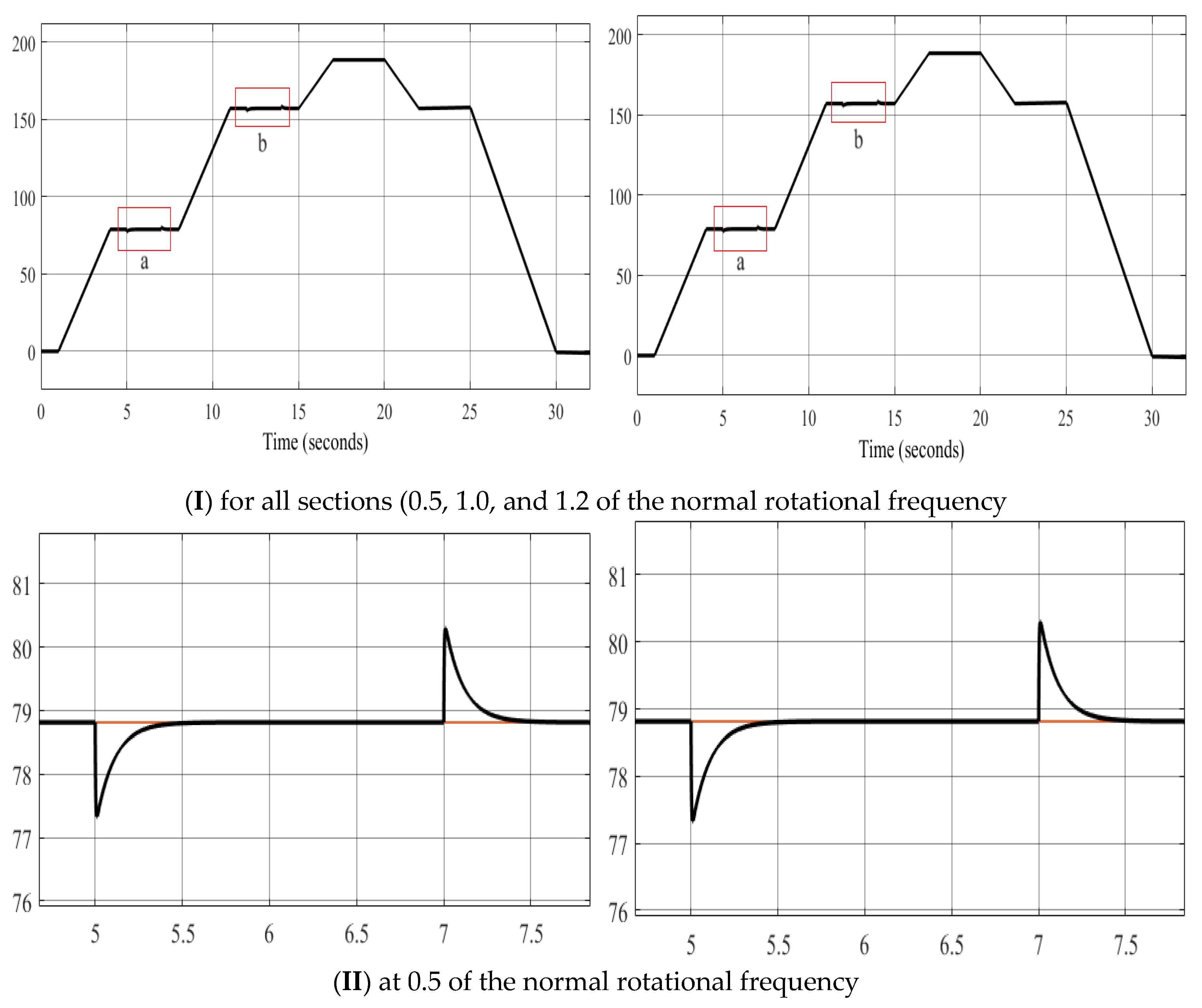
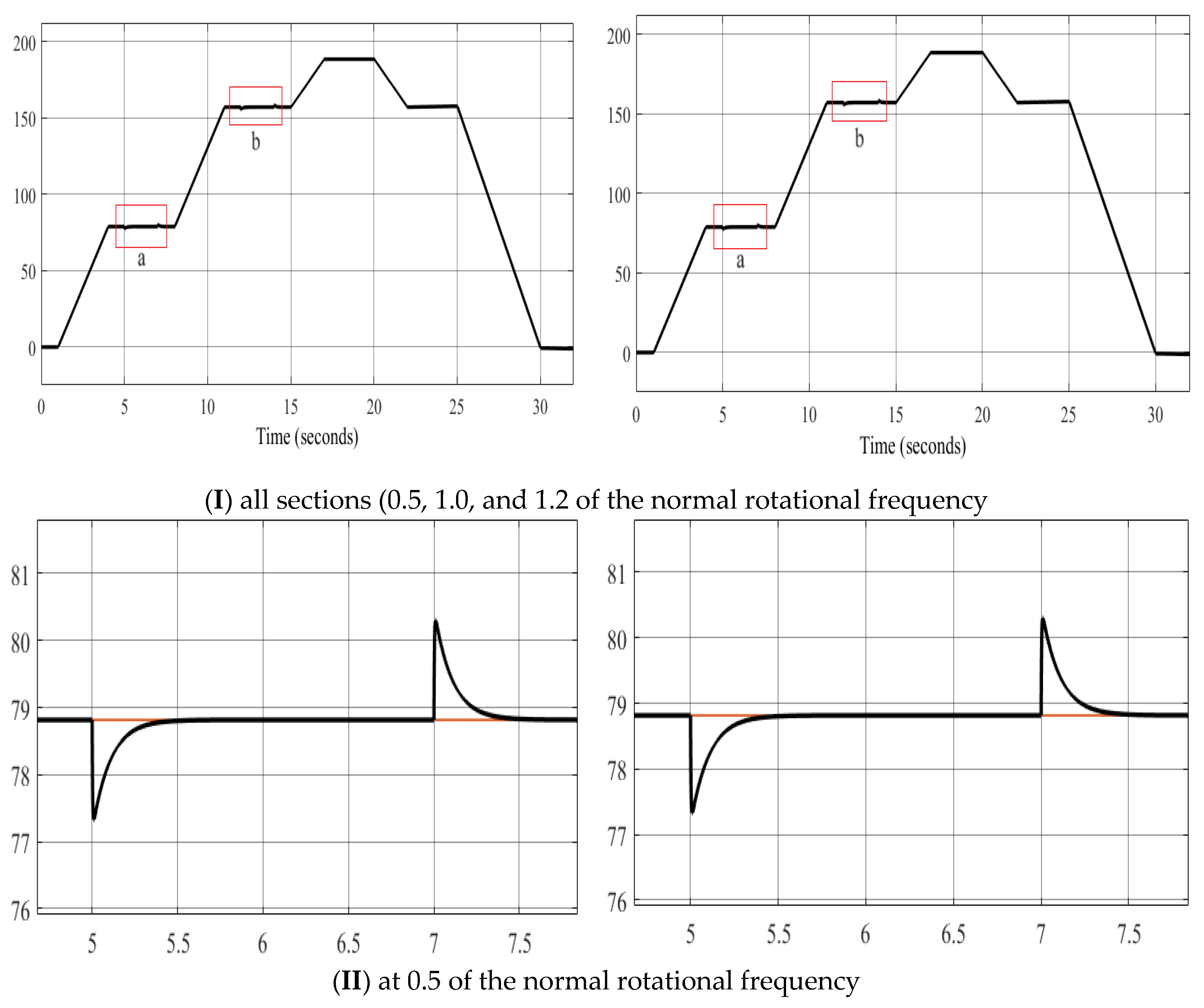
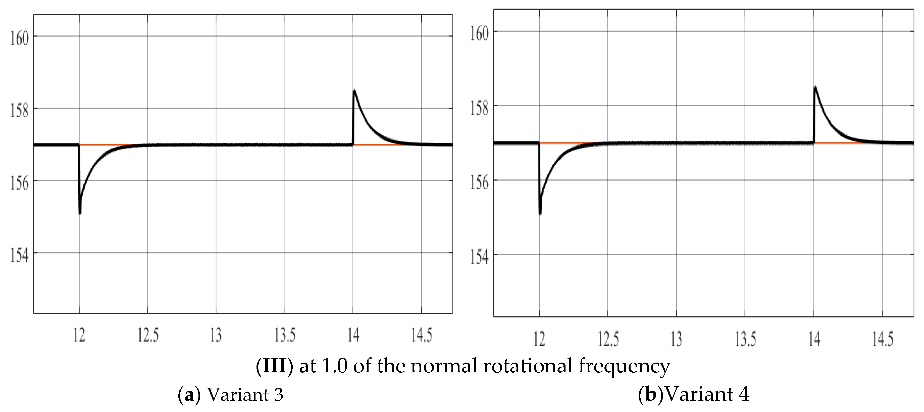
Simulation models of asynchronous drives are constructed in Matlab/Simulink based on Figure 1, Figure 10 and Figure 11 and Table 6. The simulation results are presented in Figures 12–15.
Figure 10. Structural diagram of the direct control system based on a three-level inverter and PI controllers.
Preprints 94424 g010
Figure 11. Static characteristic of the relay regulator.
Preprints 94424 g011
Performing oscillography of the following variables: rotation speed; stator flux linkage, electric torque; voltage on the capacitors, average switching frequency of transistors, stator currents and its distortion coefficient for various options.
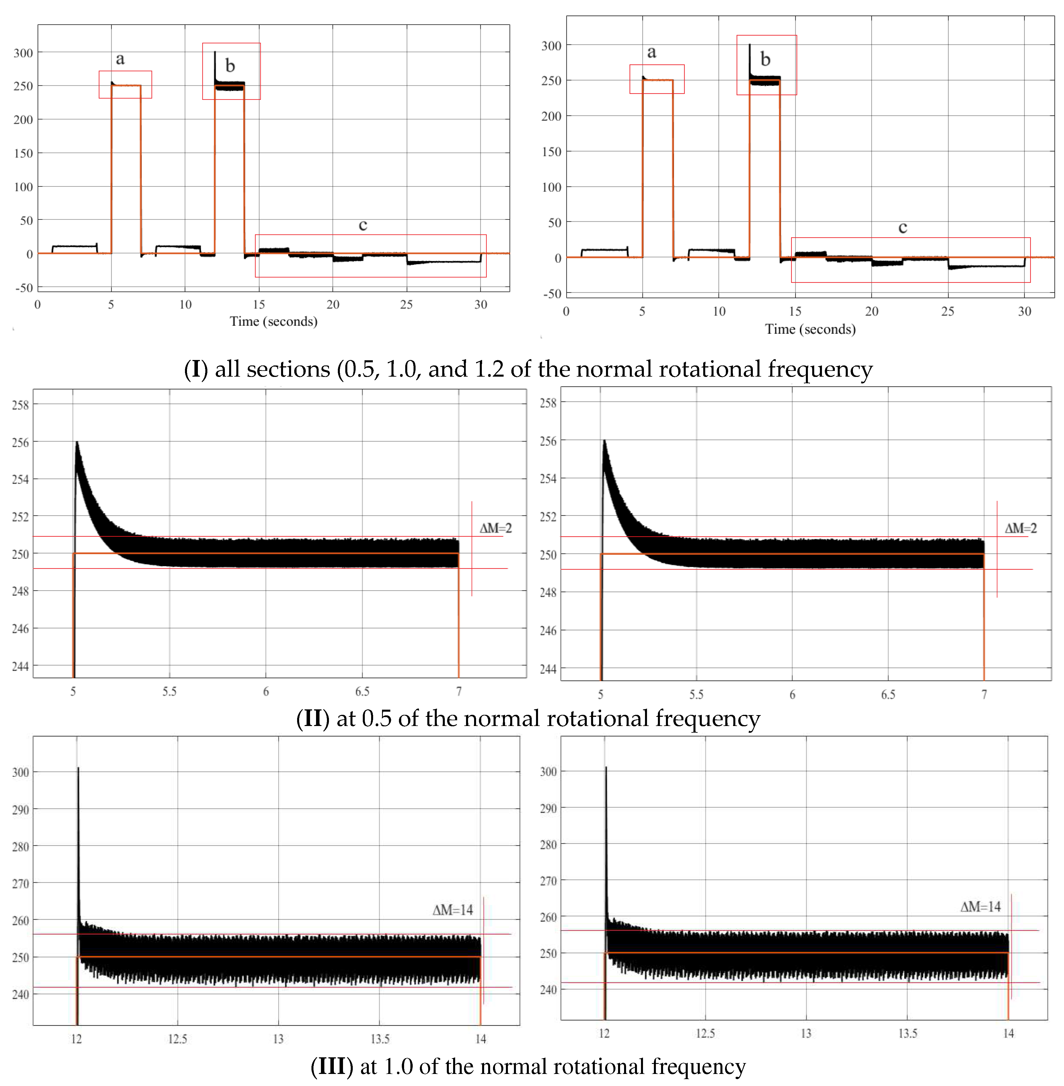
Figure 12a. Rotational frequency.
Preprints 94424 g012aPreprints 94424 g012b
Figure 12b. Rotational frequency.
Preprints 94424 g013aPreprints 94424 g013b
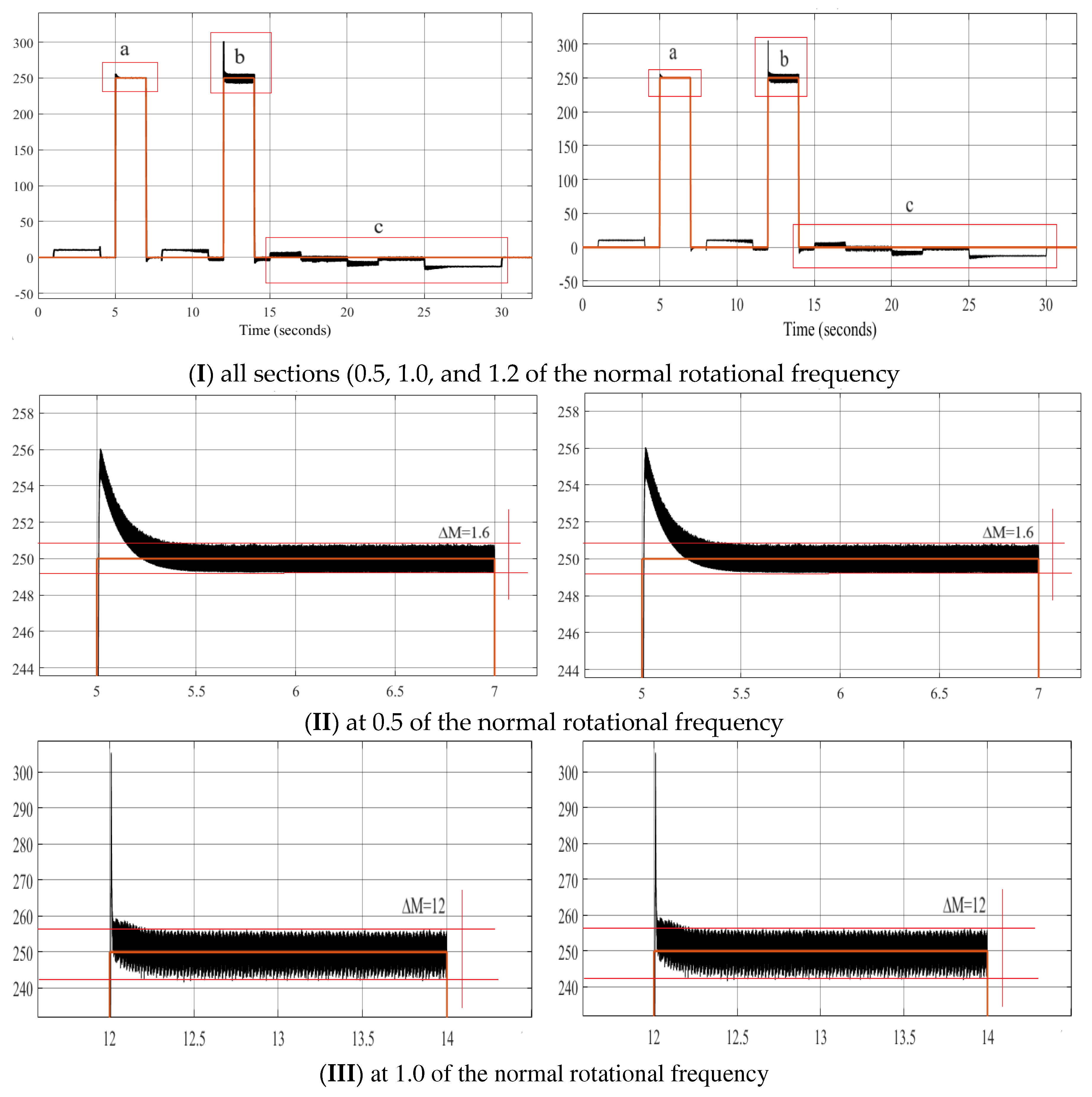
Figure 13a. Electrical torque.
Preprints 94424 g014aPreprints 94424 g014b
Figure 13b. Electrical torque.
Preprints 94424 g015aPreprints 94424 g015b
Figure 14a. Research results for Variant 1–2.
Preprints 94424 g016
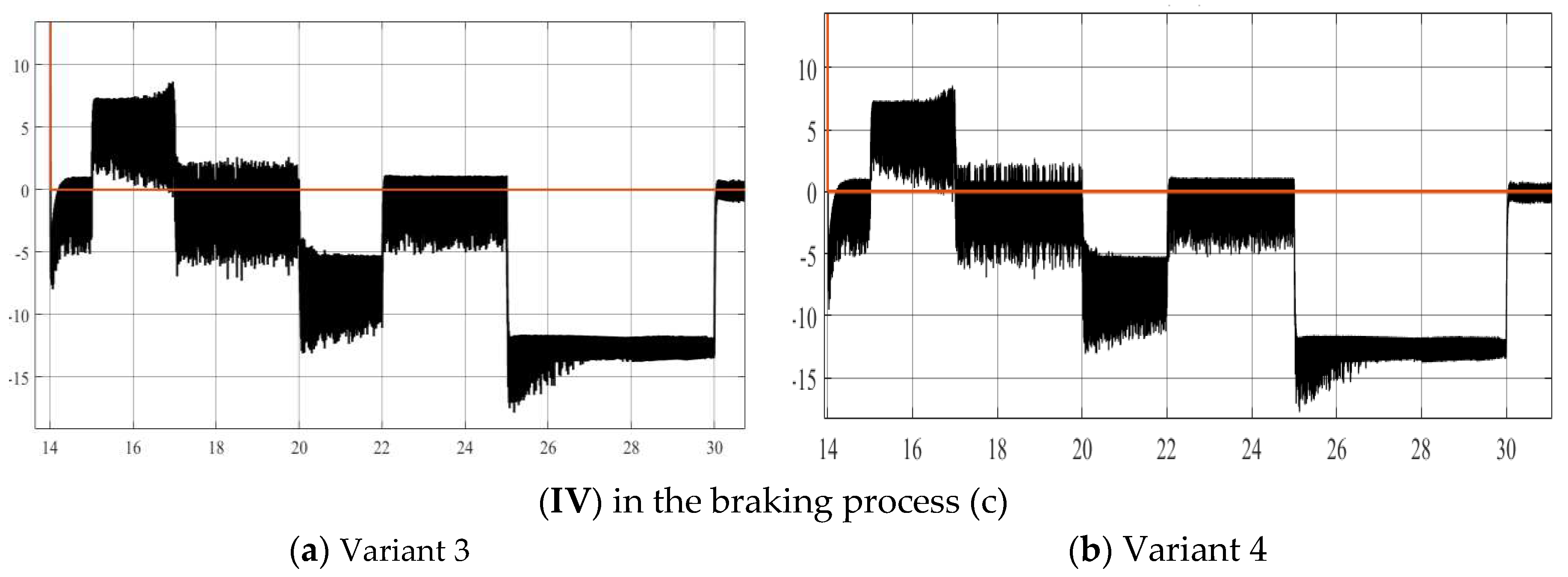
Figure 14b. Research results for Variant 3–4.
Preprints 94424 g017
Figure 15a. Research results for Variant 1–2.
Preprints 94424 g018
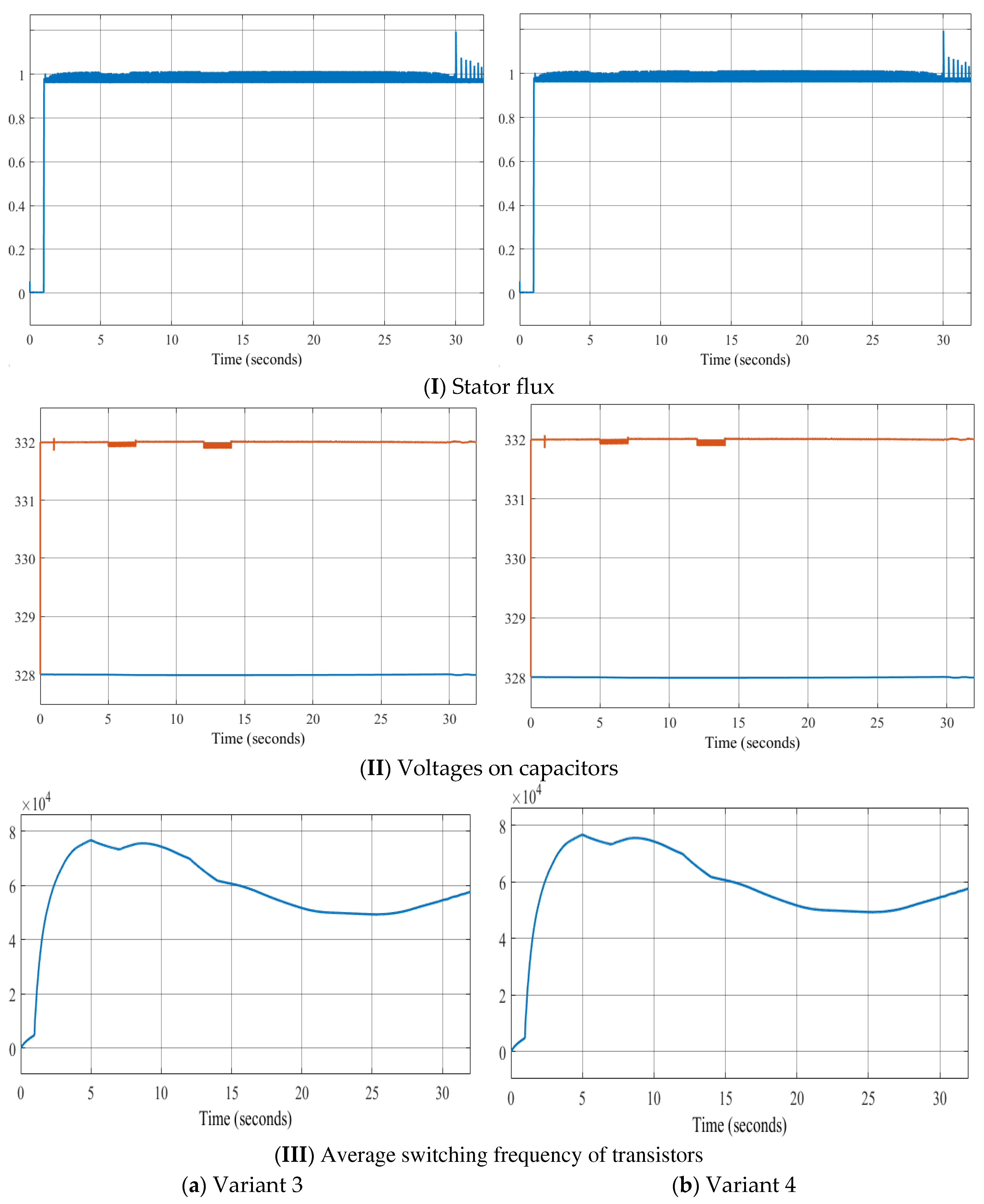
Figure 15b. Research results for Variant 3–4.
Preprints 94424 g019

4. Discussion of the obtained results

The four short vector application variants have identical speed waveforms at 0.5, 1.0, and 1.2 normalized rotation frequencies with a load of Mc = 250 Nm. The rotation frequency coincides with the set frequency and requires only 0.3 s to reach a steady-state speed after setting the load. The application of a three-level autonomous inverter and the proposed voltage switching table allows for an expansion of the motor rotation frequency control range (from 0 to 1.2 normalized).
Almost identical waveforms for flux linkage, capacitor voltage, and average transistor switching frequency.
From the torque waveforms at different segments, it is observed that variants 3 and 4 provide better characteristics compared to variants 1 and 2, reducing the pulsating torque oscillation by 20% at 0.5 normalized rotation frequency and 15% at 1.0 normalized rotation frequency.
From the current waveforms and the results in Table 7, the investigation of current distortion shows that using six vectors U1–6 to reduce torque and U8–13 to increase torque yields the best results (lowest distortion coefficient of 9.43% at 0.5 and 11.74% at 1.0 normalized rotation frequency with the lowest amplitude).
Thus, the proposed new table using six vectors U1–6 to reduce torque and U8–13 to increase torque provides better control results for the asynchronous drive with a three-level NPC inverter.

5. Conclusions

In this study, the structure and algorithm of an automated asynchronous motor drive based on direct torque control and a three-level NPC inverter have been successfully demonstrated. A voltage switching table has been proposed, and its performance has been tested through simulation using Matlab/Simulink software. The research results showed that using the proposed control table with six vectors U1–U6 to reduce torque and U8–U13 to increase torque is excellent over a wide range of motor speeds, reducing pulsating torque fluctuations, and achieving a low distortion coefficient of stator current in various operating modes. This enhances the performance and reliability of the automated asynchronous drive.

Author Contributions

Conceptualization, B.Yu. and T.H.; methodology, B.Yu.; software, T.H.; validation, B.Yu and T.H.; formal analysis, T.H.; investigation, B.Yu. and T.H.; resources, B.Yu. and T.H.; data curation, B.Yu. and T.H.; writing—original draft preparation, B.Yu. and T.H.; writing—review and editing, B.Yu. and T.H.; visualization, B.Yu. and T.H.; supervision, B.Yu.; project administration, B.Yu.; funding acquisition, T.H. All authors have read and agreed to the published version of the manuscript.

Funding

This research received no external funding.

Institutional Review Board Statement

Not Applicable.

Informed Consent Statement

Not Applicable.

Data Availability Statement

Not Applicable.

Conflicts of Interest

The authors declare no conflict of interest.

Appendix A

Table A1. Asynchronous motor parameters.
Parameter Measurement Value
Nominal Power kW 55
Nominal Voltage V 380
Frequency Hz 50
Stator Resistance Ohm 0,12
Stator Inductance mH 0,19
Nominal Speed rad/s 157
Rotor Resistance Ohm 0,4258
Rotor Inductance mH 0,0053
Mutual Inductance mH 51
Moment of Inertia kg·m² 0.4
Number of Pole Pairs 2

References

  1. Wróblewski, A.; Krot, P.; Zimroz, R.; Mayer, T.; Peltola, J. Review of Linear Electric Motor Hammers—An Energy-Saving and Eco-Friendly Solution in Industry. Energies 2023, 16, 959. [Google Scholar] [CrossRef]
  2. Sychev, Yu.A.; Zimin, R.Yu. Improving the quality of electricity in the power supply systems of the mineral resource complex with hybrid filter-compensating devices. Journal of Mining Institute 2021, 247, 132–140. [Google Scholar] [CrossRef]
  3. Nazarychev, A.N.; Dyachenok, G.V.; Sychev, Yu.A. A reliability study of the traction drive system in haul trucks based on failure analysis of their functional parts. Journal of Mining Institute 2023, 261, 363–373. [Google Scholar]
  4. Nepsha, F.S.; Varnavskiy, K.A.; Voronin, V.A.; Zaslavskiy, I.S.; Liven A., S. Integration of renewable energy at coal mining enterprises: problems and prospects. Journal of Mining Institute 2023, 261, 455–469. [Google Scholar]
  5. Abramovich, B.N.; Bogdanov, I.A. Improving the efficiency of autonomous electrical complexes of oil and gas enterprises. Journal of Mining Institute. 2021. Vol.249, p.408-416. [CrossRef]
  6. Shpenst, V.A.; Belsky, A.A.; Orel, E.A. Improving the efficiency of autonomous electrical complex with renewable energy sources by means of adaptive regulation of its operating modes. Journal of Mining Institute 2023, 261, 479–492. [Google Scholar]
  7. Marusin, A.; Tian, H.; Safiullin, R.; Safiullin, R.; Marusina, I. Integral Evaluation of the Effectiveness of the Implementation of Automated Technical Means of Controlling the Movement of Vehicles on the Road. In Proceedings of the 2022 International Conference on Engineering Management of Communication and Technology (EMCTECH), Vienna, Austria, 20–22 October 2022; pp. 1–4. [Google Scholar] [CrossRef]
  8. Zhukovskiy, Y. L.; Korolev, N. A.; Malkova, Y. M. Monitoring of grinding condition in drum mills based on resulting shaft torque. Journal of Mining Institute 2022, 256, 686–700. [Google Scholar] [CrossRef]
  9. Zhukovskiy, Yu. L.; Vasilev, B. Y.; Korolev, N. A.; Malkova, Y. M. Analysis of the behavior of asynchronous electric drive with a closed scalar control system when changing the inductance of the magnetizing circuit. Indonesian Journal of Science and Technology 2023, 8, 65–78. [Google Scholar] [CrossRef]
  10. Du, J.; Li, Y. Analysis on the Variation Laws of Electromagnetic Force Wave and Vibration Response of Squirrel-Cage Induction Motor under Rotor Eccentricity. Electronics 2023, 12, 1295. [Google Scholar] [CrossRef]
  11. Drabek, T. Derating of Squirrel-Cage Induction Motor Due to Rotating Harmonics in Power Voltage Supply. Energies 2023, 16, 735. [Google Scholar] [CrossRef]
  12. Baros, J.; Sotola, V.; Bilik, P.; Martinek, R.; Jaros, R.; Danys, L.; Simonik, P. Review of Fundamental Active Current Extraction Techniques for SAPF. Sensors 2022, 22, 7985. [Google Scholar] [CrossRef]
  13. Ikram Saady; Mohammed Karim; Badre Bossoufi; Najib El Ouanjli; Saad Motahhir; Btissam Majout. Optimization and control of photovoltaic water pumping system using kalman filter based MPPT and multilevel inverter fed DTC-IM, Results in Engineering, Volume 17, 2023, 100829, ISSN 2590-1230. [CrossRef]
  14. Borse, P.S.; Thakre, M.P.; Matale, N.P. 5-level torque-hysteresis controller for DTC based IM drive. International Journal of Engineering, Science and Technology 2022, 14, 104–111. [Google Scholar] [CrossRef]
  15. Elamri, O.; Oukassi, A.; El Bahir, L.; El Idrissi, Z. Combined Vector and Direct Controls Based on Five-Level Inverter for High Performance of IM Drive. World Electric Vehicle Journal 2022, 13, 17. [Google Scholar] [CrossRef]
  16. El Idrissi, A.; Derouich, A.; Mahfoud, S.; El Ouanjli, N.; Chantoufi, A.; Al-Sumaiti, AS.; Mossa, MA. Bearing Fault Diagnosis for an Induction Motor Controlled by an Artificial Neural Network—Direct Torque Control Using the Hilbert Transform. Mathematics 2022, 10, 4258. [Google Scholar] [CrossRef]
  17. Kamalapur, G.; Muni, T.V.; Kumar, P.R.; Parimala, V.; Kishore, K.V.; Aspalli, M.S. A Novel Neuro Fuzzy Method DTC of Induction Motor Drive for Efficient Torque Response. 2022 3rd International Conference for Emerging Technology (INCET), Belgaum, India, 2022, pp. 1-7. [CrossRef]
  18. Kamalapur, G.; Aspalli, M. S. Direct torque control and dynamic performance of induction motor using fractional order fuzzy logic controller. International Journal of Electrical and Computer Engineering (IJECE) 2023, 13, 3805–3816. [Google Scholar] [CrossRef]
  19. Albalawi, H.; Zaid, S.A.; El-Shimy, M.E.; Kassem, A.M. Ant Colony Optimized Controller for Fast Direct Torque Control of Induction Motor. Sustainability 2023, 15, 3740. [Google Scholar] [CrossRef]
  20. Savarapu, S.; Qutubuddin, M.; Narri, Y. Modified Brain Emotional Controller-Based Ripple Minimization for SVM-DTC of Sensorless Induction Motor Drive. IEEE Access 2022, 10, 40872–40887. [Google Scholar] [CrossRef]
  21. Matthew Liam De Klerk; Akshay Kumar Saha. Performance analysis of DTC-SVM in a complete traction motor control mechanism for a battery electric vehicle, Heliyon, Volume 8, Issue 4, 2022, e09265, ISSN 2405-8440. [CrossRef]
  22. Yu, Y.; Zhao, Y.; Wang, B.; Huang, X.; Xu, D. Current Sensor Fault Diagnosis and Tolerant Control for VSI-Based Induction Motor Drives. IEEE Transactions on Power Electronics 2018, 33, 4238–4248. [Google Scholar] [CrossRef]
  23. El Ouanjli; N. Mahfoud; S. Bhaskar; M.S. et al. A new intelligent adaptation mechanism of MRAS based on a genetic algorithm applied to speed sensorless direct torque control for induction motor. Int. J. Dynam. Control 2022, 10, 2095–2110. [CrossRef]
  24. Najib El Ouanjli; Said Mahfoud; Ameena Saad Al-Sumaiti; Soukaina El Daoudi; Aziz Derouich; Mohammed El Mahfoud; Mahmoud A. Mossa. Improved twelve sectors DTC strategy of induction motor drive using Backstepping speed controller and P-MRAS stator resistance identification-design and validation, Alexandria Engineering Journal, Volume 80, 2023, Pages 358-371, ISSN 1110-0168. [CrossRef]
  25. Thakre, M.P.; Borse, P.S. Analytical Evaluation of FOC and DTC Induction Motor Drives in Three Levels and Five Levels Diode Clamped Inverter. 2020 International Conference on Power, Energy, Control and Transmission Systems (ICPECTS), Chennai, India, 2020, pp. 1-6. [CrossRef]
  26. Jnayah, S.; Moussa, I.; Khedher, A. IM Fed by Three-Level Inverter under DTC Strategy Combined with Sliding Mode Theory. Electronics. 2022; 11(22):3656. [CrossRef]
  27. Elamri, O.; Oukassi, A.; El Bahir, L.; El Idrissi, Z. Combined Vector and Direct Controls Based on Five-Level Inverter for High Performance of IM Drive. World Electric Vehicle Journal. 2022; 13(1):17. [CrossRef]
  28. Sahri, Y.; Tamalouzt, S.; Belaid, S. L.; Bajaj, M.; Belkhier, Y.; Singh, A. R., ... & Kamel, S. Effectiveness analysis of twelve sectors of DTC based on a newly modified switching table implemented on a wind turbine DFIG system under variable wind velocity. Ain Shams Engineering Journal 2023, 102221. [CrossRef]
  29. Debdouche, N.; Deffaf B.; Benbouhenni H.; Laid, Z.; & Mosaad M. I. Direct Power Control for Three-Level Multifunctional Voltage Source Inverter of PV Systems Using a Simplified Super-Twisting Algorithm. Energies 2023, 16, 4103. [CrossRef]
  30. Jnayah, S.; Moussa, I.; Khedher, A. IM fed by three-level inverter under DTC strategy combined with sliding mode theory. Electronics 2022, 11, 3656. [Google Scholar] [CrossRef]
  31. Fathima, A. S.; Roykumar, M.; & Cherian, E. Depletion of Torque Ripple in Induction Motor Using Direct Torque Control Technique Incorporating Novel Multilevel Inverter Topology. In 2023 3rd Asian Conference on Innovation in Technology (ASIANCON) (pp. 1-6). 2023, August, IEEE.
  32. Vasilev, B. U.; Nguyen, T. H. Influence of semiconductor converters on asynchronous drive battery and motor in mining machines. MIAB. Mining Inf. Anal. Bull. 2023; (9-1):299-318. [In Russ]. [CrossRef]
  33. Maklakov, A. S.; Erdakov, I. N. Study of Behavior of Voltage and Current Spectra of Three-Level Neutral Point Clamped Converter at Selected Harmonic Elimination Programmed Pulse Pattern Pulse-Width Modulation. Energies 2023, 16, 5183. [Google Scholar] [CrossRef]
  34. T. H. Nguyen, and B. Y. Vasilev. Analysis of the impact of Autonomous Inverter Control Algorithms on the Battery and Motor // 2022 International Russian Automation Conference (RusAutoCon), Sochi, Russian Federation. 2022, pp. 649-654. [CrossRef]
  35. Sieklucki, G.; Sobieraj, S.; Gromba, J.; & Necula, R. E. Analysis and Approximation of THD and Torque Ripple of Induction Motor for SVPWM Control of VSI. Energies 2023, 16, 4628. [CrossRef]
Figure 1. Block diagram of an automated asynchronous drive based on a three-level inverter NPC.
Preprints 94424 g001
Figure 2. Equivalent circuit of an automated asynchronous drive based on a three-level inverter NPC.
Preprints 94424 g002
Figure 3. Variant 1.
Preprints 94424 g003
Figure 4. Variant 2.
Preprints 94424 g004
Figure 5. Variant 3.
Preprints 94424 g005
Figure 6. Variant 4.
Preprints 94424 g006
Figure 7. Various options for studying random switching frequencies.
Preprints 94424 g007
Figure 8. Average switching number of inverter transistors.
Preprints 94424 g008
Table 1. The research results of Ua and Ia in Matlab/Simulink without L–filters.
Variant UA(1) THD IA(1) THD
1 86.12 35.74 49.74 35.73
2 86.14 35.72 49.74 35.73
3 86.13 35.67 49.74 35.67
4 85.95 35.66 49.63 35.64
5 86.18 35.90 49.74 35.72
6 86.10 35.64 49.73 35.75
7 86.11 35.79 49.74 35.70
8 86.20 35.64 49.74 35.73
Table 2. The research results of Ua and Ia in Matlab/Simulink with the installation of L–filters.
Variant UA (1) THD IA(1) THD
1 86.13 35.97 47.45 4.15
2 86.14 35.98 47.46 3.04
3 85.89 36.04 47.31 3.54
4 85.93 35.97 47.34 3.52
5 86.17 36.04 47.46 3.53
6 86.10 35.90 47.75 3.51
7 86.11 35.99 47.46 3.53
8 86.17 35.95 47.46 3.56
Table 3. The maximum amplitudes of voltage and current distortion without L–filters.
Variant Region
I II III IV
Un(max) In(max) Un(max) In(max) Un(max) In(max) Un(max) In(max)
1 10.9 10.9 11.9 11.9 4.6 4.7 4.7 4.7
2 0.3 0.3 10.9 10.9 0.3 0.3 11.9 11.9
3 7.3 7.3 7.5 7.4 2.7 2.4 7.1 7.1
4 6.9 7.4 7.6 7.7 4.5 4.5 6.9 6.8
5 4.2 7.1 8.7 7.0 1.0 1.3 6.5 7.6
6 8.6 7.1 5.6 7.1 1.6 1.2 7.9 7.6
7 4.2 7.0 8.7 7.2 2.4 2.6 6.4 6.5
8 8.5 7.3 5.4 7.1 2.4 2.6 8.6 6.9
Table 4. The maximum amplitudes of voltage and current with the installation of L–filters
Variant Region
I II III IV
Un(max) In(max) Un(max) In(max) Un(max) In(max) Un(max) In(max)
1 11.4 2.3 12.1 1.2 4.7 0.2 3.7 0.1
2 0.3 0.08 11.0 1.0 0.5 0.02 12.1 0.5
3 7.3 1.2 7.6 0.6 2.7 0.12 7.1 0.3
4 7.0 1.2 7.7 0.6 2.5 0.11 7.0 0.3
5 4.5 1.4 8.7 0.6 1.0 0.07 6.6 0.3
6 8.7 1.4 5.6 0.7 1.6 0.07 8.0 0.3
7 5.4 1.3 8.6 0.7 2.4 0.13 6.5 0.3
8 8.3 1.3 5.3 0.7 2.4 0.14 8.7 0.3
Table 5. Possible switching states of the voltage rows.
State Sx1 Sx2 Sx3 Sx4
P 1 1 0 0
O 0 1 1 0
N 0 0 1 1
Table 6. Voltage Switching Table.
dM Sector
1 2 3 4 5 6 7 8 9 10 11 12
+1 +3 15 21 16 22 17 23 18 24 19 25 14 20
+2 20 15 21 16 22 17 23 18 24 19 25 14
+1 2/9 2/9 3/10 3/10 4/11 4/11 5/12 5/12 6/13 6/13 1/8 1/8
0 0 0 7 7 26 26 0 0 7 7 26 26
-1 6/13 6/13 1/8 1/8 2/9 2/9 3/10 3/10 4/11 4/11 5/12 5/12
-2 25 14 20 15 21 16 11 17 23 18 24 06
-3 19 25 14 20 15 21 16 22 17 23 18 24
0 +3 16 22 17 23 18 24 19 25 14 20 15 21
+2 21 16 22 17 23 18 24 19 25 14 20 15
+1 3/10 3/10 4/11 4/11 5/12 5/12 6/13 6/13 1/8 1/8 2/9 2/9
0 26 26 0 0 7 7 26 26 0 0 7 7
-1 5/12 5/12 6/13 6/13 1/8 1/8 2/9 2/9 3/10 3/10 4/11 4/11
-2 24 19 25 14 20 15 21 16 22 17 23 18
-3 18 24 19 25 14 20 15 21 16 22 17 23
Table 7. Results of the investigation of current distortion in different periods T.
Variant 1 2 3 4
1T time 6 sec U(1) 110.8 107.7 100.1 102.4
THD 40.61% 39.18% 35.02% 36.22%
10T time 6 sec U(1) 118.3 120.1 119.7 119.3
THD 11.64% 11.40% 12.41% 9.43%
1T time 13 sec U(1) 103.2 103.5 104.1 108
THD 42.04% 41.58% 40.98% 36.78%
10T time 13 sec U(1) 117.8 117 117 116.8
THD 14.79 23.21% 12.85% 11.74%
Disclaimer/Publisher’s Note: The statements, opinions and data contained in all publications are solely those of the individual author(s) and contributor(s) and not of MDPI and/or the editor(s). MDPI and/or the editor(s) disclaim responsibility for any injury to people or property resulting from any ideas, methods, instructions or products referred to in the content.
Copyright: This open access article is published under a Creative Commons CC BY 4.0 license, which permit the free download, distribution, and reuse, provided that the author and preprint are cited in any reuse.
Prerpints.org logo

Preprints.org is a free preprint server supported by MDPI in Basel, Switzerland.

Subscribe

© 2024 MDPI (Basel, Switzerland) unless otherwise stated