1. Introduction
Global satellite navigation system (GNSS) has become one of the most widely used navigation systems because of its advantages of high precision, all-weather, continuous positioning, extensive coverage, convenience and flexibility [
1,
2]. As the demand for navigation performance rises, GNSS will inevitably be affected by the specific application scenario and the movement characteristics of the carrier, such as low signal carrier-to-noise ratio (
) environments (e.g., signal blocking and interference) and high dynamic motion [
3,
4,
5,
6].
GNSS receivers acquire position, velocity, and time (PVT) information by tracking satellite broadcast signals in real time, demodulating navigation messages, and acquiring pseudo-range, Doppler frequency, and other observation information. Therefore, the tracking loop accuracy of the receiver directly determines the PVT accuracy. Consequently, the accuracy of the receiver's tracking loop is a direct determinant of the precision in PVT estimation. Traditional GNSS receivers usually adopt scalar tracking loops (STL) to track each satellite independently using individual pre-assigned channel, and the signal processing among each channel is independent of each other. This tracking mode is simple to implement, without interference and pollution between channels [
7]. However, it ignores the inherent correlation of GNSS tracking loops to the receiver’s PVT information, so information cannot be shared between each channel. In contrast, vector tracking loops (VTL) interlink the tracking loops and navigation solutions of diverse channels, facilitating the exchange of information between them, which has been widely concerned in recent years [
8,
9,
10,
11]. Compared with the STL, the VTL exploits and makes full use of the redundant information of different satellite signals and the intrinsic coupling between signal tracking and navigation solution, and its advantages mainly include: 1) with the aid of navigation information, VTL mitigates the dynamic stress on the tracking loop, enhancing the dynamic performance of the receiver; 2) VTL excels in balance the correlation of information between receiver signal channels, showcasing superior performance in scenarios involving weak signal tracking and rapid retracking; 3) it also exhibits superior anti-interference performance.
In general, STL tracks satellite signals by using conventional tracking loops (CTL) based on classical control theory, encompassing phase locking loops (PLL), frequency locking loops (FLL), and delay locking loops (DLL). The characteristics of CTL are determined by noise bandwidth and loop order. Notably, the selection of noise bandwidth involves a delicate trade-off between achieving low noise and maintaining high dynamic performance. Within the VTL, the dynamic stress of the loop filter is significantly alleviated through the incorporation of feedback information, which allows the tracking loop to concentrate exclusively on thermal noise, crystal frequency error, and dynamic residual [
12,
13]. Consequently, there is an opportunity to diminish the loop bandwidth, simultaneously improving tracking accuracy. It is important to note, however, that the loop bandwidth remains constrained by crystal frequency errors and feedback errors. In complex environments, signals may be affected by high dynamics, shadows, strong attenuation, multipath effects, or ionospheric scintillation, in which scenarios the performance of fixed-bandwidth tracking loop will deteriorate or even become ineffective. Therefore, the adaptive loop tracking (ALT) technology has garnered substantial research attention due to its ability to dynamically adjust the loop bandwidth in response to the varying noise levels encountered in different scenarios [
14,
15,
16]. The contribution of the [
17] derives the Doppler aiding error due to the uncertainty of the navigation error in the GPS/INS ultra-tight integration, and designs a PLL loop filter whose noise bandwidth can be adaptively adjustable according to the performance of the integrated navigation and the
of the GPS signal. In the [
18], the adaptive scalar tracking techniques used by the fast adaptive bandwidth (FAB), the fuzzy logic (FL), and the loop-bandwidth control algorithm (LBCA) are delineated. A meticulous analysis of the tracking performance and time complexity of each method is conducted. These techniques dynamically adjust the loop bandwidth based on predefined discriminant criteria, thereby optimizing tracking performance for different scenarios. However, the adaptability of these adjustments is contingent upon specific discriminant criteria and thresholds.
Kalman filter (KF) based on optimal estimation theory stands out as an alternative method for dynamically adjusting loop noise bandwidth, gaining substantial attention in recent years owing to its superior performance in comparison to CTL [
19,
20]. The KF-based tracking loops replace conventional loop filters by estimating the loop parameters (e.g., carrier phase, Doppler frequency, and code phase) as state variables. Recherche process noise covariance
Q and measurement noise covariance
R enable KF to optimally adjust its gain coefficient in time-varying scenarios to achieve minimum mean square error (MMSE) criterion. Therefore, the real-time estimation and adjustment of
Q and
R play a crucial role in determining the filtering accuracy for time-varying scenarios. Numerous studies have delved into methods for adjusting KF parameters. Tang et al. [
21,
22] analyzes the relationship between the equivalent bandwidth of KF-based tracking loop and noise covariance, subsequently deducing the criteria for parameter setting. In [
23], variational Bayesian (VB) theory is employed to dynamically estimate the measurement noise matrix, which improves the tracking accuracy in high dynamic scenes. Moreover, the process noise matrix can be adaptively tuned based on the characteristics of the crystal oscillator and receiver dynamics in STL [
24]. However, there is a scarcity of research regarding the implementation of KF-based tracking loops in the VTL.
According to the different measurement information used, the signal tracking based on KF usually has two forms: one structure uses the output of traditional discriminator as measurement information and is implemented by linear KF; the other structure is measured by coherent integration results and implemented by nonlinear KF. Unfortunately, the loop discriminator introduces nonlinear noise in highly dynamic applications, deviating from the Gaussian white noise (GWN) property, thereby constraining the estimation accuracy. Therefore, in order to improve the tracking accuracy and dynamic range, the entire discriminator and tracking loop filter are replaced by a nonlinear tracking filter. In this case, the measurement is the outcome of the correlation between the input signal and the local signal, showcasing a nonlinear relationship with the estimated vector. Therefore, the application of a nonlinear filtering method is essential to achieve improved accuracy. Tang et al. [
25] provides a comprehensive analysis of the practical implementation architecture for tracking loops based on extended Kalman filters (EKF). Zeng et al. [
26] compared the EKF-based tracking loop of GPS receiver with the CTL, demonstrating that the EKF-based tracking loop excels in both high dynamic and tracking accuracy. Nevertheless, the EKF algorithm is a sub-optimal filtering algorithm based on nonlinear functionalization and adopts approximation or neglect method for higher order terms to solve nonlinear problems [
27]. In the case of strong nonlinearity, it may result in a significant estimation error and even lead to filter divergence. Moreover, in practical applications, the computational complexity of obtaining the derivative of the Jacobian matrix for nonlinear functions is substantial.
To address the challenges inherent in the EKF, alternative methods such as the particle filter (PF) and unscented Kalman filter (UKF) have been proposed for nonlinear filtering problems [
28,
29]. PF, a recursive Bayesian filtering (BF) method, employs random samples to represent the posterior probability distribution of system state variables, overcoming certain limitations of EKF. However, PF requires a substantial number of particles to achieve high-precision estimation, resulting in a significant computational burden, particularly in scenarios with a high update rate for the tracking loop, which makes it difficult to operate in real time. The UKF is a method for approximating nonlinear distributions using a deterministic sampling strategy, which relies on the Unscented Transform (UT) and maintains the framework of a linear KF. In contrast to PF, the UKF replaces random sampling with deterministic sampling, while maintaining comparable computational complexity to the EKF. However, the performance is better than EKF, making it a widely adopted choice for nonlinear filtering [
30,
31].
Inspired by the above research, a vector tracking receiver has been developed that leverages an adaptive square root UKF (ASRUKF) tracking loops to enhance the precision and robustness of GNSS receivers in complex dynamic environments. The primary contributions of this research are as follows:
- 1)
A vector receiver model based on a nonlinear tracking loop is designed, with comprehensive details provided on its implementation. The discriminator and traditional filter in the tracking loop are substituted with the UKF, and the Doppler feedback calculated by the navigation solution is incorporated into the loop filter. It accomplishes not only the loop tracking assistance by Doppler frequency but also establishes indirect connections between each channel, fostering mutual assistance.
- 2)
To enhance the stability and robustness of the tracking loop, the square root filter is introduced into UKF. Additionally, the measurement noise covariance and process noise covariance of UKF are adjusted adaptively according to the signal and feedback information error, respectively. This adaptive adjustment enables real-time modification of the loop noise bandwidth, consequently enhancing the performance of the tracking loop.
- 3)
The effectiveness of the proposed method was verified through field vehicle experiments conducted on urban roads. Software-defined receiver (SDR) with different structures were developed to facilitate performance comparison and analysis. The results affirm that the KF-based VTL offers a substantial improvement over the CTL-based VTL, while demonstrating that the tracking accuracy of the UKF-based VTL surpasses that of the EKF-based VTL. Moreover, the ASRUKF-based VTL exhibits further performance improvement in complex dynamic environments.
The structure of this paper is organized as follows. In
Section 2, the overall model of the vector tracking receiver is divided into three parts to describe in detail.
Section 3 describes the design method of tracking loop based on adaptive square root UKF. In
Section 4, the proposed VTL architecture is evaluated in a practical scenario and its performance is compared and analyzed within the SDR framework. Eventually, the conclusions and prospects are summarized in
Section 5.
2. System Model of Vector Tracking
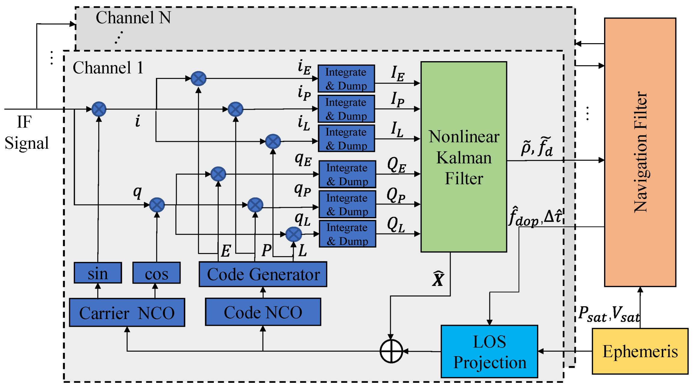
Generally, VTL receiver primarily comprises three components: nonlinear KF-based tracking loop; navigation solution module, and vector feedback calculation. The structure block diagram is illustrated in
Figure 1.
The GNSS intermediate frequency (IF) signal is correlated with the local signal to obtain the I/Q components, which are then processed by the loop filter to generate pseudo-range and Doppler frequency information as the measurement of the navigation solution. After the navigation filter estimates the receiver’s PVT information, the satellite line-of-sight (LOS) vector for each channel is calculated by incorporating the satellite ephemeris information. Then, the feedback code phase and Doppler frequency are calculated and combined with the loop filtering results to adjust the local numerically controlled oscillator (NCO), thereby establishing a closed-loop system. The EKF is typically employed in the navigation solution module, resulting in the development of a cascaded vector tracking structure with the nonlinear KF-based tracking loop. This proposed structure not only lowers the update rate of the navigation filter but also reduces computational complexity and enhances ease of implementation.
2.1. Nonlinear KF-based Tracking Loop
Given that the discriminator is substituted with a loop filter, the I/Q information is utilized directly as the measurement for KF. The state vector to be estimated comprises the following components: signal amplitude
, code phase error
, carrier phase error
, carrier frequency error
, and carrier frequency rate error
. The system model can be formulated as follows:
where the coefficient
is utilized to convert the cycles into chips, enabling unit conversion (e.g., for GPS L1:
). The value
represent the process noises of the signal amplitude, code phase error, clock bias, clock drift and frequency rate error, respectively.
The I/Q correlation values serve as the measurement of the filter, expressed in terms of:
The variables , , and represent the ‘prompt’, ‘early’, and ‘late’ correlation results of the In-phase correlator, respectively. Similarly, , , and represent the corresponding correlation results of the Quadrature-phase correlator.
The expression for the output of loop correlation value I/Q has been formulated:
where
is the navigation message,
is the autocorrelation function,
is the coherence integration time, represents the duration over which the received signals are integrated to estimate the coherence function.
is the correlator interval. For the early, prompt, and late branches,
are -1, 0, and +1 respectively. Additionally,
and
represent zero-mean GWN that is independent of the I/Q branches. The average carrier phase error
in the coherent integration time
is computed according to the following formula:
Note that the Equation (3) signifies a nonlinear relationship between the measurement and the state vector of the tracking loop.
2.2. Nonlinear KF-based Tracking Loop
The VTL employs the EKF instead of the least square (LS) method to fuse pseudo-range and Doppler frequency for calculating the optimal PVT solution. This decision is based on its superior filtering performance and simplified fault detection and isolation capabilities.
The state vector representing the navigation solution is outlined as follows:
where
is the errors vector of position in ECEF coordinate system;
is the corresponding velocity errors vector.
and
refer to the errors associated with clock bias and drift of receiver.
The system adopts the constant velocity model, thus enabling the expression of the discrete state transition matrix of the system as follows:
where
represents the navigation filter update time,
is a three-dimensional identity matrix.
The measurement of the navigation filter consists of the difference between the calculated and estimated pseudo-range, along with the Doppler frequency for each channel:
The variables and represent the measured pseudo range and Doppler frequency of channel m respectively, while and denote the estimated pseudo-range and Doppler frequency correspondingly.
The matrix representing the transfer of measurements is presented below [
32]:
where, is the LOS vector from the receiver to the
m-th satellite, calculation as follows:
where,
and
represent the position vectors of the receiver and the
m-th satellite respectively.
2.3. Nonlinear KF-based Tracking Loop
When the PVT information is estimated by the navigation filter, the carrier and code NCO feedback correction information of each channel can be calculated by combining the satellite ephemeris.
The Doppler frequency estimation of the tracking channel
j at time
k can be computed as follows:
where
and
are the receiver velocity and the velocity of the channel
j satellite, respectively, while
denotes the clock drift at time
k. Additionally,
corresponds to the carrier frequency (e.g., for GPS L1
), and
signifies the velocity of light (e.g.,
).
Combined with the results of the loop filter, the final carrier frequency is:
where,
is the IF signal of the RF front-end output, and
is the
n-th element of the state vector
of tracking loop at time
k.
As evident from the Equation (11), the incorporation of Doppler frequency significantly alleviates the dynamic stress of the loop. This not only enhances the dynamic performance of the receiver, but also allows the loop filter to further decrease the noise bandwidth, consequently improving tracking accuracy and sensitivity.
Accordingly, the estimation of code frequency can be calculated directly using a carrier Doppler assisted form:
The code phase is computed according to the following procedure:
where is the length of the pseudo-code chip (e.g., for GPS L1 signal: ).
Furthermore, following the completion of the NCO update, the state vector is reset to zero, thereby initiating the subsequent cycle’s state estimation process.
3. Proposed Adaptive SRUKF-based Loop Tracking
The tracking loop filter can be represented by a nonlinear state space model:
where,
denotes the state vector and
is the measurement vector, while
and
are nonlinear functions of the system and measurement model, respectively. The vectors
and
correspond to process noise and measurement noise with zero-mean and covariance
and
, respectively.
3.1. Square Root Unscented Kalman Filter
The UKF utilizes sigma points to approximate the functional probability density distribution, thereby facilitating nonlinear filtering. However, the necessity of calculating sigma points at each update, which involves taking the square root of the state covariance matrix, can lead to issues such as computational burden and numerical instability. By integrating the concept of square root filtering within the UKF framework, it is possible to reduce computational complexity and enhance efficiency. This is achieved through direct recursion updating in the form of the square root of the covariance matrix. Moreover, this approach guarantees the non-negativity of the covariance matrix, effectively prevents filter divergence, and fosters the convergence speed and numerical stability of the filter.
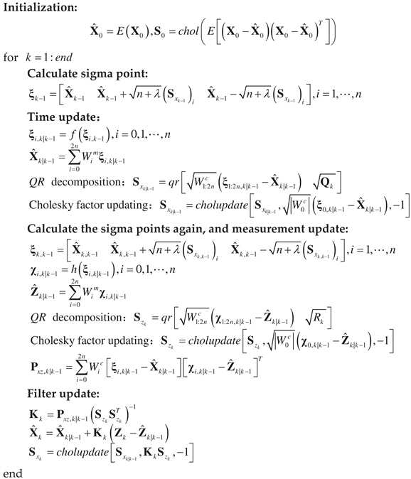
The Square Root Unscented Kalman Filter (SRUKF) utilizes
QR decomposition and
Cholesky factor update techniques to replace the covariance matrix with its square root, thereby enhancing the efficiency of the filtering iteration. The specific procedural steps are delineated in
Table 1.
3.2. Adaptive SRUKF-based Loop Tracking for Vector Tracking
In the VTL, different from STL, the tracking loop can eliminate most of the dynamic stress with the assistance of Doppler frequency. However, this also introduces additional frequency errors due to navigation inaccuracies. Beyond addressing loop thermal noise and receiver crystal error, the tracking loop also tracks the Doppler auxiliary error induced by navigation error, which constitutes the majority of the tracking error. Given the uncertainty of navigation solution error, the signal dynamics generated by the navigation solution cannot be optimally tracked using SRUKF-based loop filter with constant parameters.
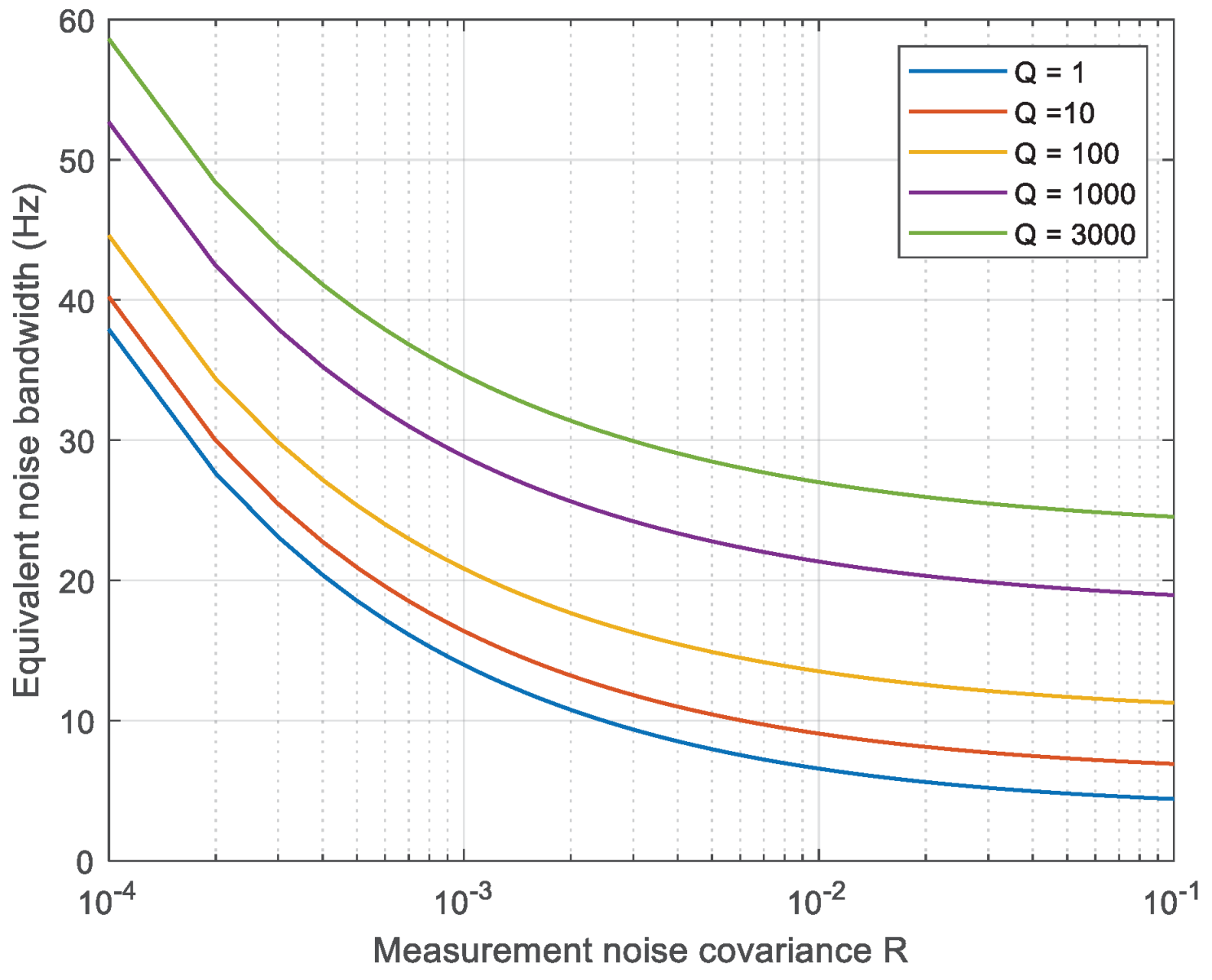
The steady-state equivalent bandwidth of the KF-based tracking loop is determined by the ratio of the process noise covariance to the measurement noise covariance (
Q/
R), and its specific value can be derived from the filter parameters [
21]. The
Figure 2 illustrates the equivalent noise bandwidth of the KF-based tracking loop in steady-state, considering various process noise covariances
Q, with respect to the measurement noise covariance
R. When the signal is weak (i.e., low
), the loop bandwidth is reduced in order to enhance noise filtering. However, excessively reducing the loop bandwidth may lead to inadequate tracking of dynamic signals during rapid fluctuations. Consequently, adaptive mechanisms are frequently employed to dynamically adjust parameters in real time based on external information, thereby achieving optimal state estimation.
The measurement noise covariance of prompt component in previous studies can be calculated by considering the
:
where,
and
can be referred to the description in the Equation (3). The signal power is denoted as
, while the
is expressed in units of
dBHz. The narrowband broadband power ratio method (NWPR) is employed in this paper for calculating the
due to its superior estimation performance when dealing with weak signals.
In addition, the noise covariance of the early and late branches is calculated as follows:
Thus, corresponding to Equation (2), the measurement noise covariance matrix
of the loop filter is represented as a diagonal matrix in the following form:
However, the determination of dynamic stress in the tracking loop solely based on is insufficient. Therefore, this research also considers adaptive adjustment of process noise covariance , which can be modified based on estimated Doppler frequency error resulting from the uncertainty of the navigation solution. Essentially, the imprecision associated with navigation error manifests the dynamics of the tracking loop, which resulting in an inherent uncertainty in the state equation.
Primarily, in accordance with Equation (10), the uncertainty of the estimated Doppler frequency is determined through the examination of the state covariance during the navigation solution process.
where
and
represent the noise covariance matrices associated with the clock drift and velocity components, respectively.
Subsequently, the process noise covariance matrix
of the loop filter is adjusted adaptively based on the Doppler frequency error covariance and thereby effectively regulate the loop noise bandwidth:
where,
signifies the initial value of state noise covariance, with the setting criteria available in reference 22. Additionally,
represents the additional process noise covariance resulting from the uncertainty associated with navigation errors.
where,
represents the scale factor governing the conversion from Doppler frequency error to process noise covariance, while
is the identity matrix of the same dimension as
. It is worth noting that
determines the sensitivity of the
matrix concerning Doppler frequency error. Therefore,
can adjust itself according to
:
It becomes evident that inverse proportionality between the sensitivity of matrix to Doppler frequency error and . The sensitivity of the Doppler error can be appropriately reduced when the is high, while a decrease in results in heightened sensitivity.


