Submitted:
26 December 2023
Posted:
26 December 2023
You are already at the latest version
Abstract
Keywords:
1. Introduction
2. Materials and experimental procedure
3. Results and discussion
3.1. Dilatometric analysis
3.2. Sintering of TiB2 with various amounts of carbon
3.3. Sintering of TiB2 with various amounts of MoSi2
3.4. Sintering of TiB2 with 2 wt.% carbon addition and various amounts of MoSi2
3.5. Mechanical properties of the composites
4. Results discussion
5. Conclusions
Acknowledgements
References
- B. Basu, G.B. B. Basu, G.B. Raju, A.K. Suri, Processing and properties of monolithic TiB2 based materials, Int. Mater. Rev. 51 (2006) 352–374. [CrossRef]
- B.R. Golla, A. B.R. Golla, A. Mukhopadhyay, B. Basu, S.K. Thimmappa, Review on ultra-high temperature boride ceramics, Prog. Mater. Sci. 111 (2020) 100651. [CrossRef]
- W.G. Fahrenholtz, G.E. W.G. Fahrenholtz, G.E. Hilmas, Ultra-high temperature ceramics: Materials for extreme environments, Scr. Mater. 129 (2017) 94–99. [CrossRef]
- T.S.R.C. Murthy, B. T.S.R.C. Murthy, B. Basu, R. Balasubramaniam, A.K. Suri, C. Subramanian, R.K. Fotedar, Processing and Properties of TiB2 with MoSi2 Sinter-additive: A First Report, J. Am. Ceram. Soc. 89 (2006) 131–138. [CrossRef]
- F. Monteverde, A. F. Monteverde, A. Bellosi, Efficacy of HfN as sintering aid in the manufacture of ultrahigh-temperature metal diborides-matrix ceramics, J. Mater. Res. 19 (2004) 3576–3585. [CrossRef]
- F. Monteverde, A. F. Monteverde, A. Bellosi, Beneficial Effects of AlN as Sintering Aid on Microstructure and Mechanical Properties of Hot-pressed ZrB2, Adv. Eng. Mater. 5 (2003) 508–512. [CrossRef]
- F. Monteverde, A. F. Monteverde, A. Bellosi, Effect of the addition of silicon nitride on sintering behaviour and microstructure of zirconium diboride, Scr. Mater. 46 (2002) 223–228. [CrossRef]
- L.-H. Li, H.-E. L.-H. Li, H.-E. Kim, E. Son Kang, Sintering and mechanical properties of titanium diboride with aluminum nitride as a sintering aid, J. Eur. Ceram. Soc. 22 (2002) 973–977. [CrossRef]
- J.-H. Park, Y.-H. Koh, H.-E. Kim, C.S. Hwang, E.S. Kang, Densification and Mechanical Properties of Titanium Diboride with Silicon Nitride as a Sintering Aid, J. Am. Ceram. Soc. 82 (2004) 3037–3042. [CrossRef]
- S.K. Bhaumik, C. Divakar, A.K. Singh, G.S. Upadhyaya, Synthesis and sintering of TiB2 and TiB2–TiC composite under high pressure, Mater. Sci. Eng. A 279 (2000) 275–281. [CrossRef]
- E.S. Kang, C.H. E.S. Kang, C.H. Kim, Improvements in Mechanical Properties of TiB2 by the Dispersion of B4C Particles, J. Mater. Sci. 4 (1989) 580.
- E.S. Kang, C.W. Jang, C.H. Lee, C.H. Kim, D.K. Kim, Effect of Iron and Boron Carbide on the Densification and Mechanical Properties of Titanium Diboride Ceramics, J. Am. Ceram. Soc. 72 (1989) 1868–1872. [CrossRef]
- F. Rodríguez-Rojas, V. Zamora, F. Guiberteau, A.L. Ortiz, Solid-state spark plasma sintering of super wear resistant B4C–SiC–TiB2 triplex-particulate composites, Ceram. Int. 49 (2023) 5532–5537. [CrossRef]
- S. Torizuka, K. Sato, J. Harada, H. Yamamoto, H. Nishio, Microstructure and Sintering Mechanism of TiB2–ZrO2–SiC Composite, J. Ceram. Soc. Jpn. 100 (1992) 392–397.
- S. Torizuka, K. Sato, H. Nishio, T. Kishi, Effect of SiC on Interfacial Reaction and Sintering Mechanism of TiB2, J. Am. Ceram. Soc. 78 (1995) 1606–1610. [CrossRef]
- Mukhopadhyay, G.B. Raju, B. Basu, Understanding Influence of MoSi2 Addition (5 Weight Percent) on Tribological Properties of TiB2, Metall. Mater. Trans. A 39 (2008) 2998–3013. [CrossRef]
- T.S.R.C. Murthy, R. Balasubramaniam, B. Basu, A.K. Suri, M.N. Mungole, Oxidation of monolithic TiB2 and TiB2–20wt.% MoSi2 composite at 850°C, J. Eur. Ceram. Soc. 26 (2006) 187–192. [CrossRef]
- T.S.R.C. Murthy, J.K. Sonber, C. Subramanian, R.K. Fotedar, S. Kumar, M.R. Gonal, A.K. Suri, A new TiB2+CrSi2 composite – Densification, characterization and oxidation studies, Int. J. Refract. Met. Hard Mater. 28 (2010) 529–540. [CrossRef]
- G.B. Raju, B. Basu, Densification, Sintering Reactions, and Properties of Titanium Diboride With Titanium Disilicide as a Sintering Aid, J. Am. Ceram. Soc. 90 (2007) 3415–3423. [CrossRef]
- G.B. Raju, A. Mukhopadhyay, K. Biswas, B. Basu, Densification and high-temperature mechanical properties of hot pressed TiB2–(0–10wt.%) MoSi2 composites, Scr. Mater. 61 (2009) 674–677. [CrossRef]
- L. Silvestroni, H.-J. Kleebe, S. Lauterbach, M. Müller, D. Sciti, Transmission electron microscopy on Zr- and Hf-borides with MoSi2 addition: Densification mechanisms, J. Mater. Res. 25 (2010) 828–834. [CrossRef]
- D. Sciti, L. Silvestroni, G. Celotti, C. Melandri, S. Guicciardi, Sintering and Mechanical Properties of ZrB2 -TaSi2 and HfB2 -TaSi2 Ceramic Composites, J. Am. Ceram. Soc. 91 (2008) 3285–3291. [CrossRef]
- L. Silvestroni, D. Sciti, Densification of ZrB2-TaSi2 and HfB2-TaSi2 Ultra-High-Temperature Ceramic Composites, J. Am. Ceram. Soc. 94 (2011) 1920–1930. [CrossRef]
- T. Watanahe, K. Shoubu, Mechanical Properties of Hot-Pressed TiB2-ZrO2 Composites, J. Am. Ceram. Soc. 68 (1985) C-34-C–36. [CrossRef]
- R. Telle, S. Meyer, G. Petzow, E.D. Franz, Sintering behaviour and phase reactions of TiB2 with ZrO2 additives, Mater. Sci. Eng. A 105–106 (1988) 125–129. [CrossRef]
- J. Schneider, K.H. Zum Gahr, R. Müller, E.. Franz, Einfluß des ZrO2-Zusatzes auf mechanische Eigenschaften und den ungeschmierten Gleitverschleiß von TiB2-ZrO2-Mischkeramiken, Materwissenchaft Und Werkstofftechnik 27 (1996) 359–366.
- Y. Muraoka, M. Yoshinaka, K. Hirota, O. Yamaguchi, Hot isostatic pressing of TiB2-ZrO2(2 mol% Y2O3) composite powders, Mater. Res. Bull. 31 (1996) 787–792. [CrossRef]
- T. Graziani, A. Bellosi, Sintering and Characterization of TiB2 -B4C-ZrO2 Composites, Mater. Manuf. Process. 9 (1994) 767–780. [CrossRef]
- ICSD 98-003-0330 Titanium Boride, (n.d.).
- M. Singh, H. Wiedemeier, Chemical Interactions in Diboride-Reinforced Oxide-Matrix Composites, J. Am. Ceram. Soc. 74 (1991) 724–727. [CrossRef]
- G.J.K. Harrington, G.E. Hilmas, W.G. Fahrenholtz, Effect of Carbon and Oxygen on the Densification and Microstructure of Hot Pressed Zirconium Diboride, J. Am. Ceram. Soc. 96 (2013) 3622–3630. [CrossRef]
- S. Baik, P.F. Becher, Effect of Oxygen Contamination on Densification of TiB2, J. Am. Ceram. Soc. 70 (1987) 527–530. [CrossRef]
- Y. Yan, Z. Huang, S. Dong, D. Jiang, Pressureless Sintering of High-Density ZrB2 ?SiC Ceramic Composites, J. Am. Ceram. Soc. 89 (2006) 3589–3592. [CrossRef]
- 8.2: Atomic and Ionic Radius, (n.d.). https://chem.libretexts.org/@go/page/98634?pdf.
- T.R. Paul, M.K. Mondal, M. Mallik, Densification behavior of ZrB2–MoSi2–SiCw composite processed by multi stage spark plasma sintering, Ceram. Int. 47 (2021) 31948–31972. [CrossRef]
- F. Monteverde, R.J. Grohsmeyer, A.D. Stanfield, G.E. Hilmas, W.G. Fahrenholtz, Densification behavior of ZrB2-MoSi2 ceramics: The formation and evolution of core-shell solid solution structures, J. Alloys Compd. 779 (2019) 950–961. [CrossRef]
- D. Sciti, F. Monteverde, S. Guicciardi, G. Pezzotti, A. Bellosi, Microstructure and mechanical properties of ZrB2–MoSi2 ceramic composites produced by different sintering techniques, Mater. Sci. Eng. A 434 (2006) 303–309. [CrossRef]
- Rabiezadeh, A.M. Hadian, A. Ataie, Synthesis and sintering of TiB2 nanoparticles, Ceram. Int. 40 (2014) 15775–15782. [CrossRef]
- M. Mashhadia, M. Shambulia, S. Safib, Effect of MoSi2 addition and particle size of SiC on pressureless sintering behavior and mechanical properties of ZrB2–SiC–MoSi2 composites, J. Mater. Res. Technol. 5 (2016) 200–205. [CrossRef]
- L. Silvestroni, S. Failla, I. Neshpor, O. Grigoriev, Method to improve the oxidation resistance of ZrB2 -based ceramics for reusable space systems, J. Eur. Ceram. Soc. 38 (2018) 2467–2476. [CrossRef]
- Krishnamurthy, C. Subramanian, Issues in the synthesis and fabrication of refractory carbides, borides, silicides and their mixtures, in: T. Ohji, M. Singh (Eds.), Process. Manuf. Technol. Struct. Multifunct. Mater., John Wiley & Sons, Inc., Hoboken, New Jersey, 2000: pp. 69–79.
- T. Dasgupta, J. Etourneau, B. Chevalier, S.F. Matar, A.M. Umarji, Structural, thermal, and electrical properties of CrSi2, J. Appl. Phys. 103 (2008). [CrossRef]
- R. Rosenkranz, G. Frommeyer, Microstructures and Properties of the Refractory Compounds TiSi2 and ZrSi2, Int. J. Mater. Res. 83 (1992) 685–689. [CrossRef]
- Y. Jeng, E.J. Lavernia, Processing of molybdenum disilicide, J. Mater. Sci. 29 (1994) 2557–2571.
- T. Nakano, K. Hagihara, Y. Nakai, Y. Umakoshi, Plastic deformation behavior of NbSi2/MoSi2 crystals with oriented lamellae, Intermetallics 14 (2006) 1345–1350. [CrossRef]
- H. Inui, M. Moriwaki, S. Ando, M. Yamaguchi, Plastic deformation of single crystals of CrSi2 with the C40 structure, Mater. Sci. Eng. A 239–240 (1997) 63–68. [CrossRef]
- Z. Fu, R. Koc, Microstructure and mechanical properties of hot pressed submicron TiB2 powders, Ceram. Int. 44 (2018) 9995–9999. [CrossRef]
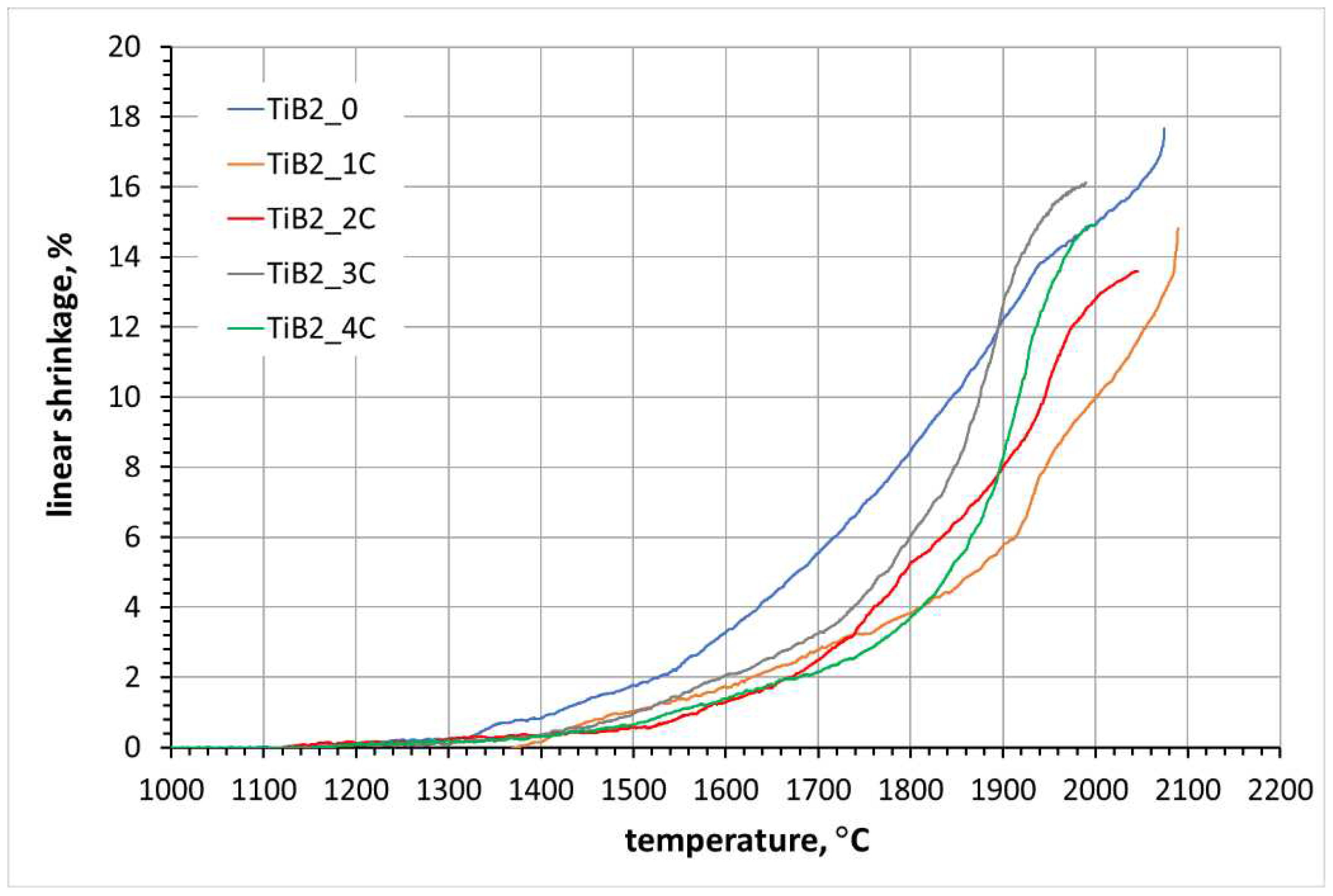
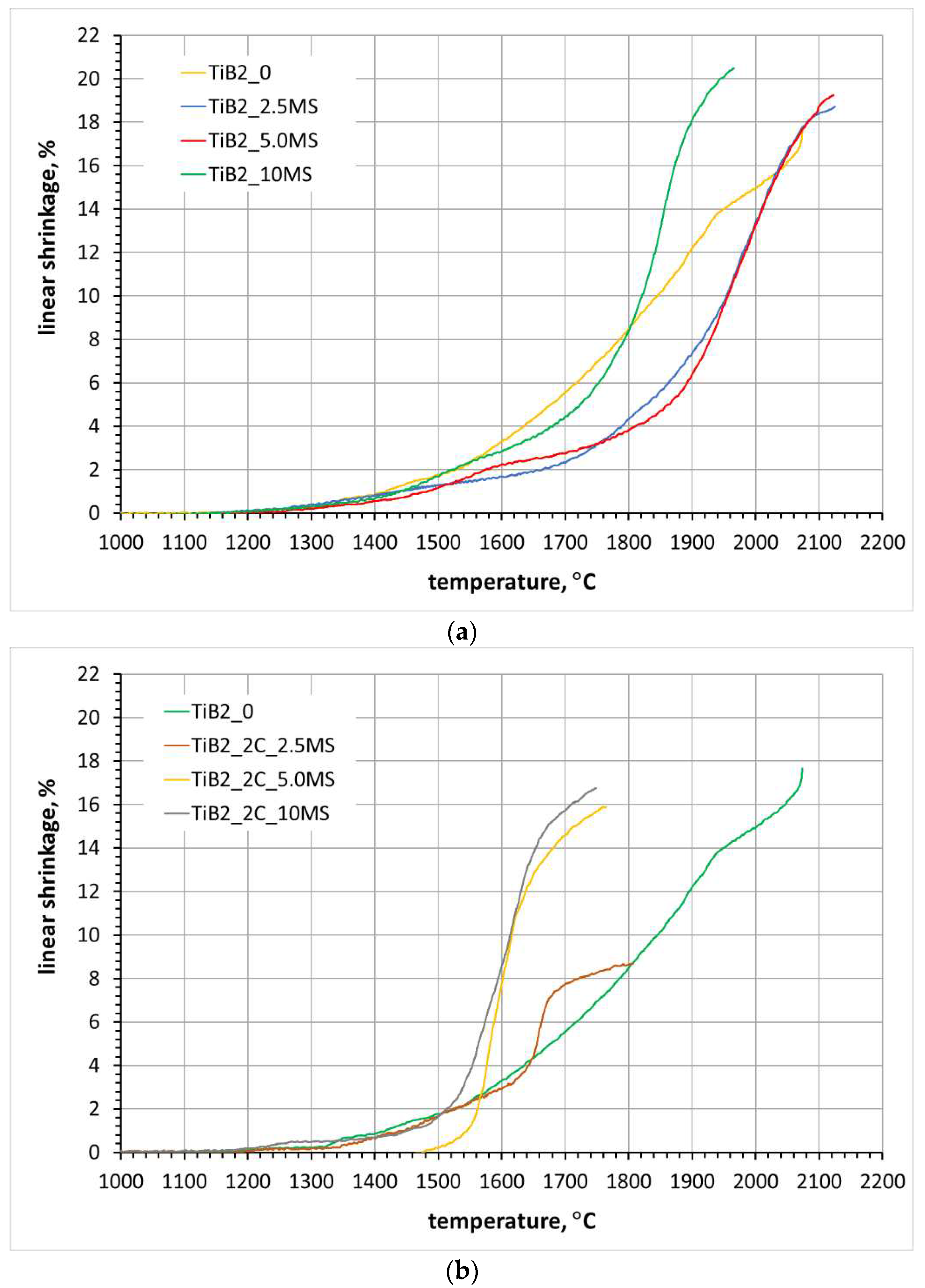
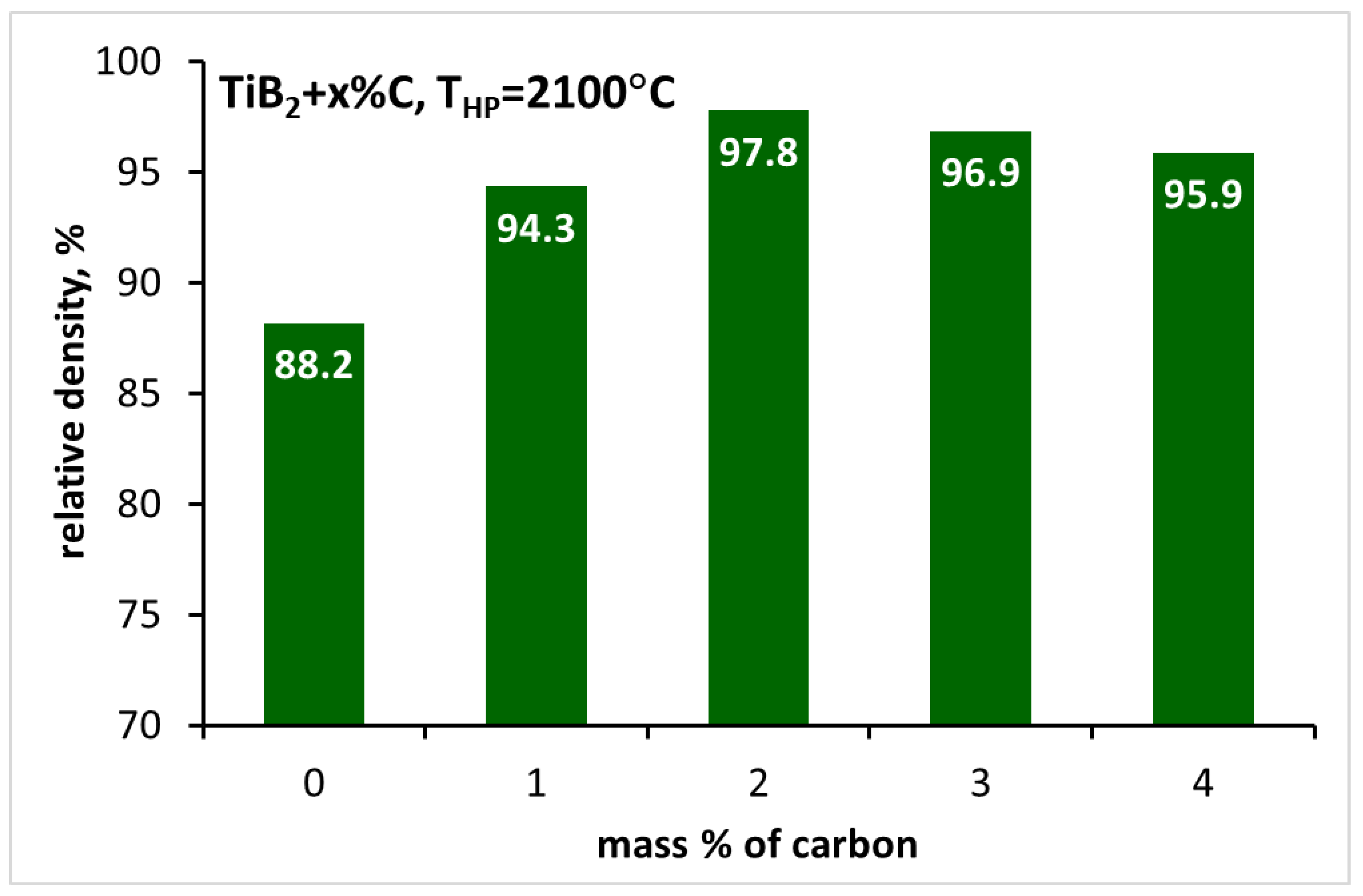
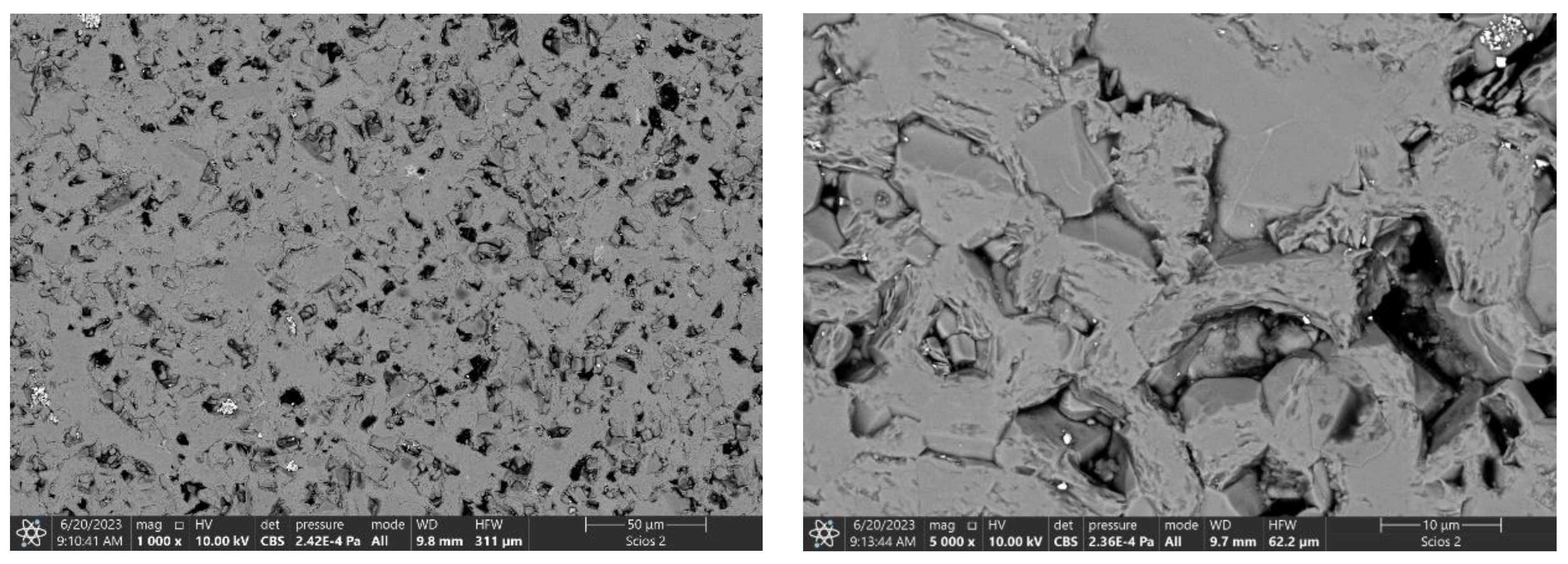
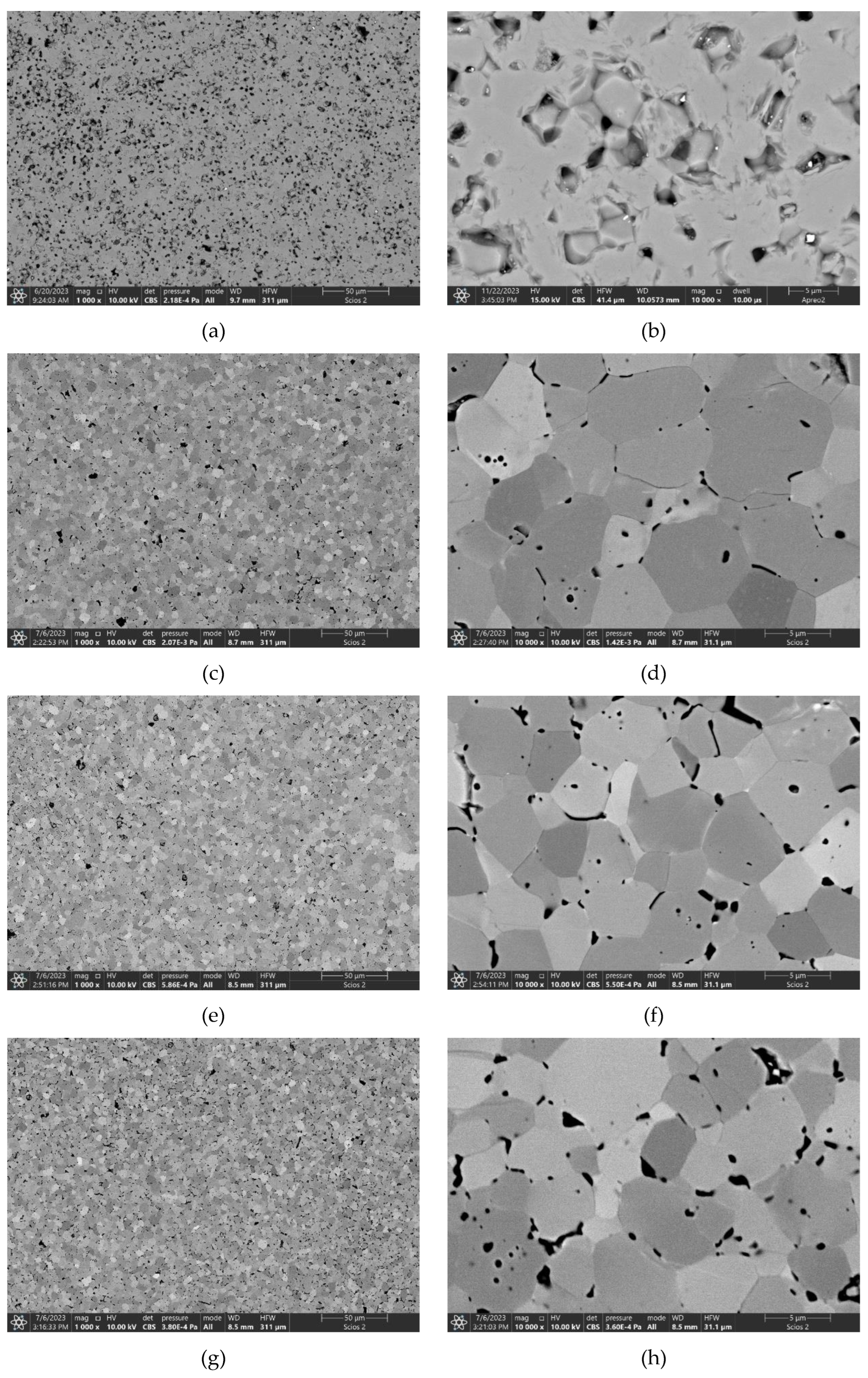
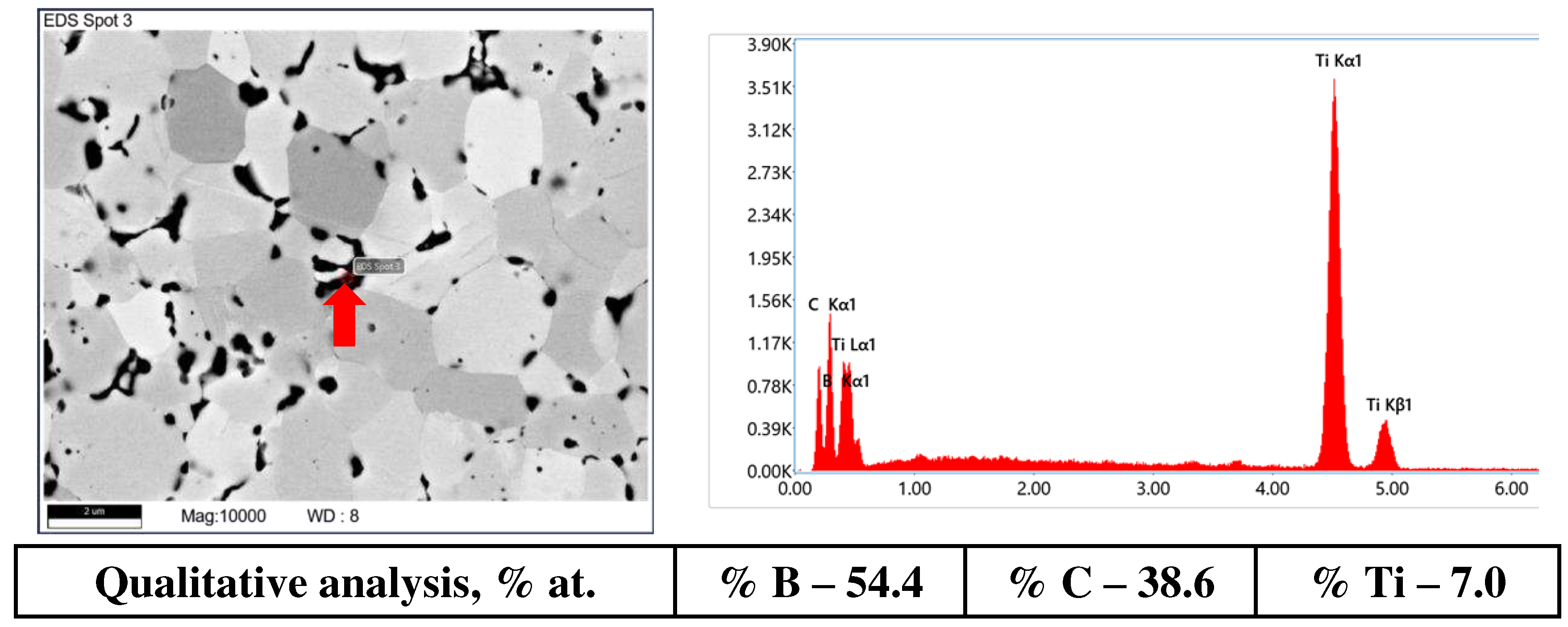
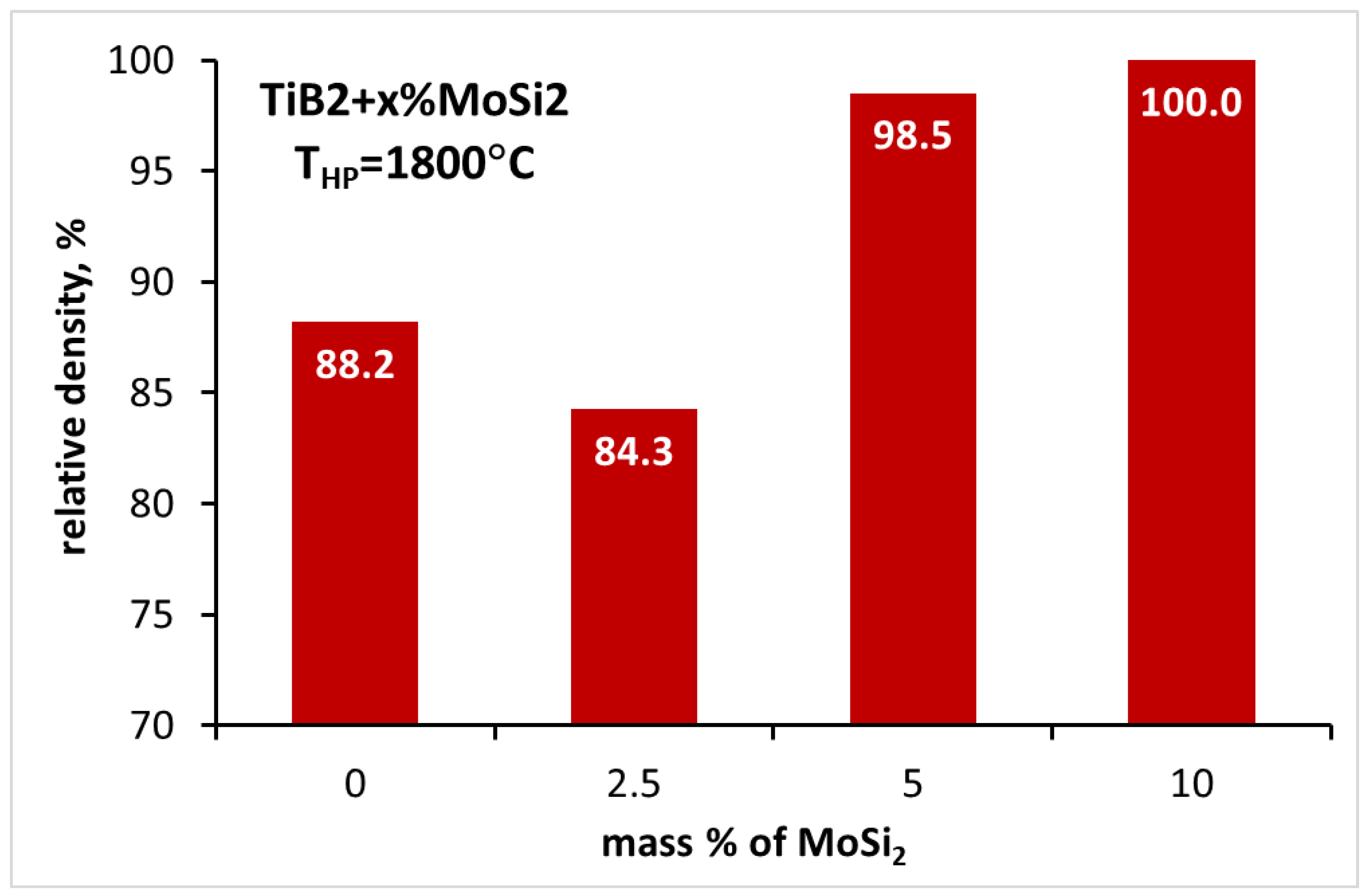
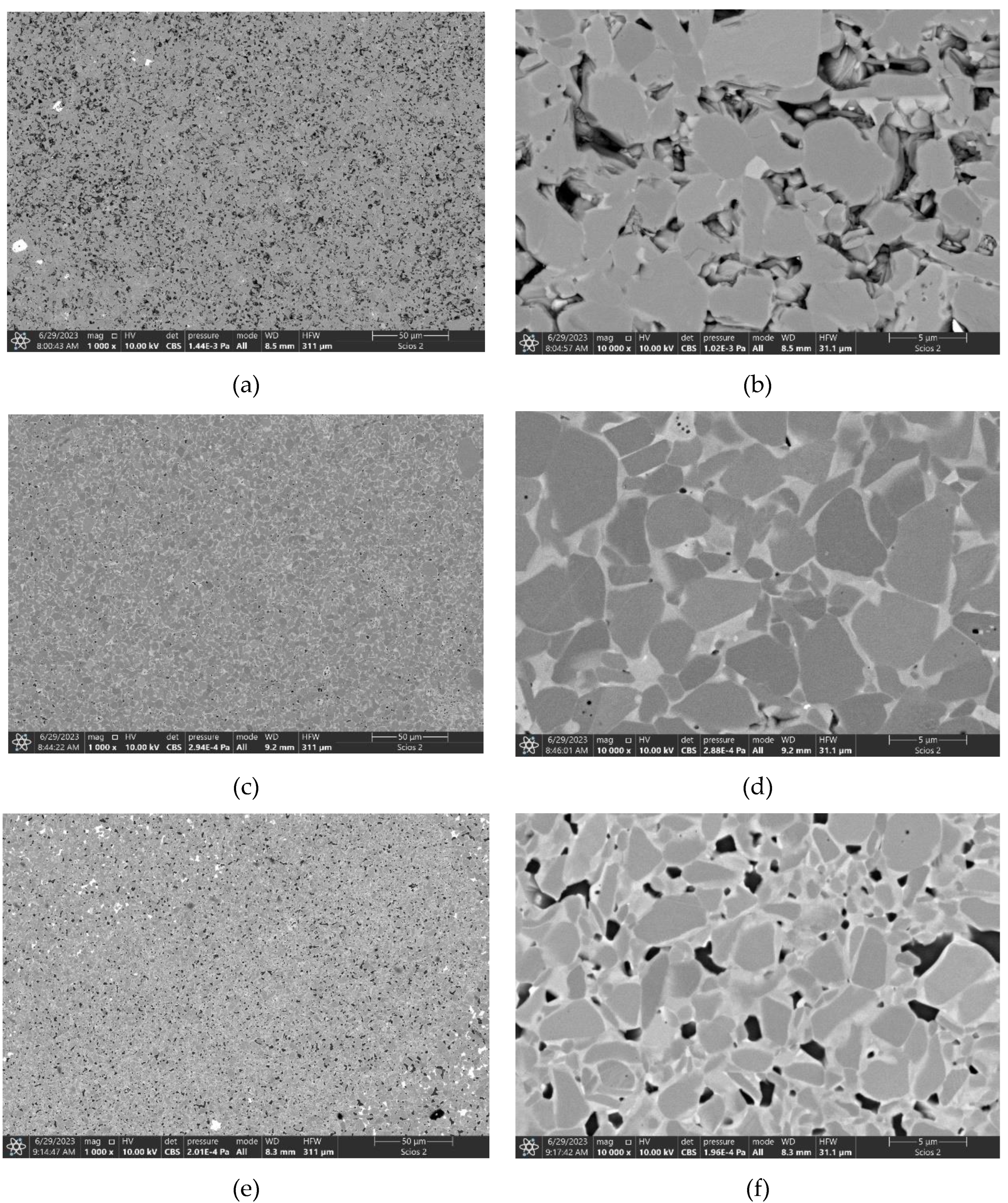
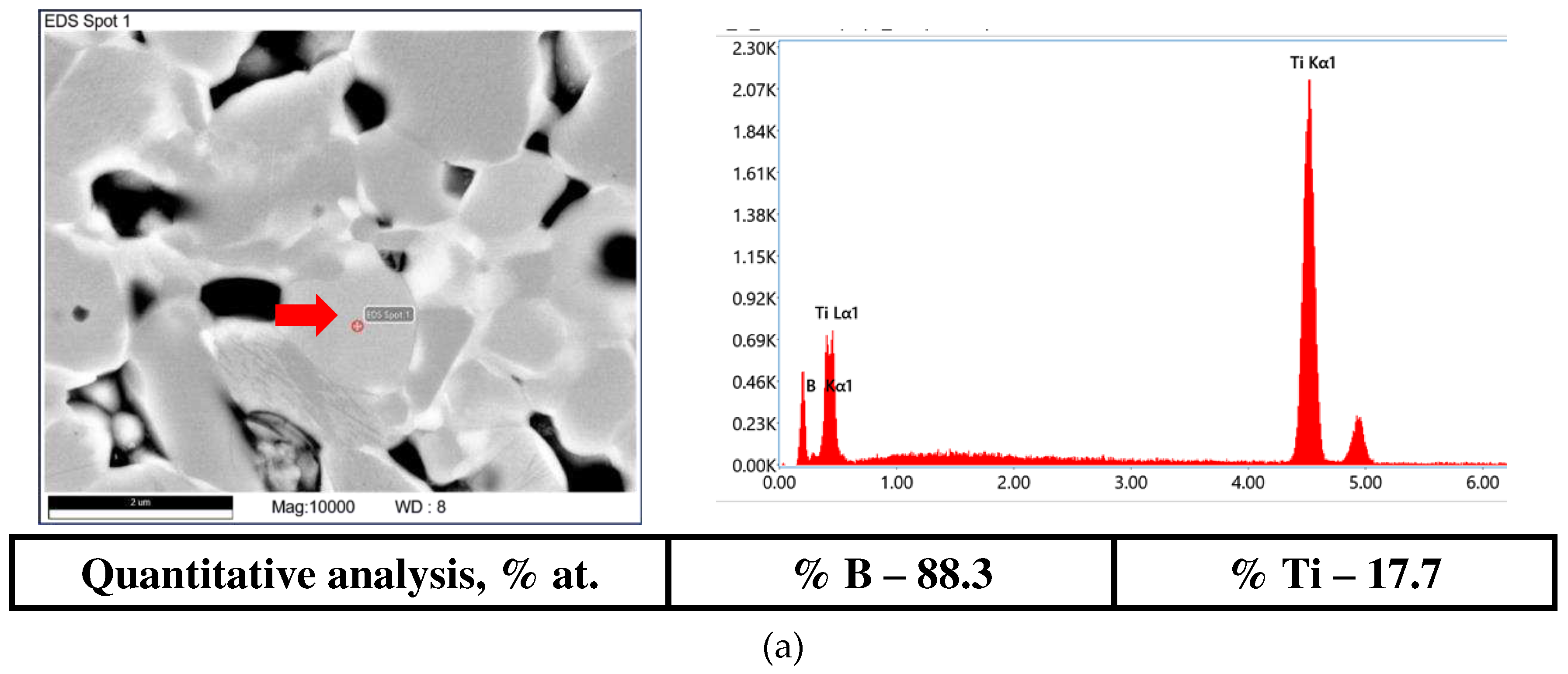
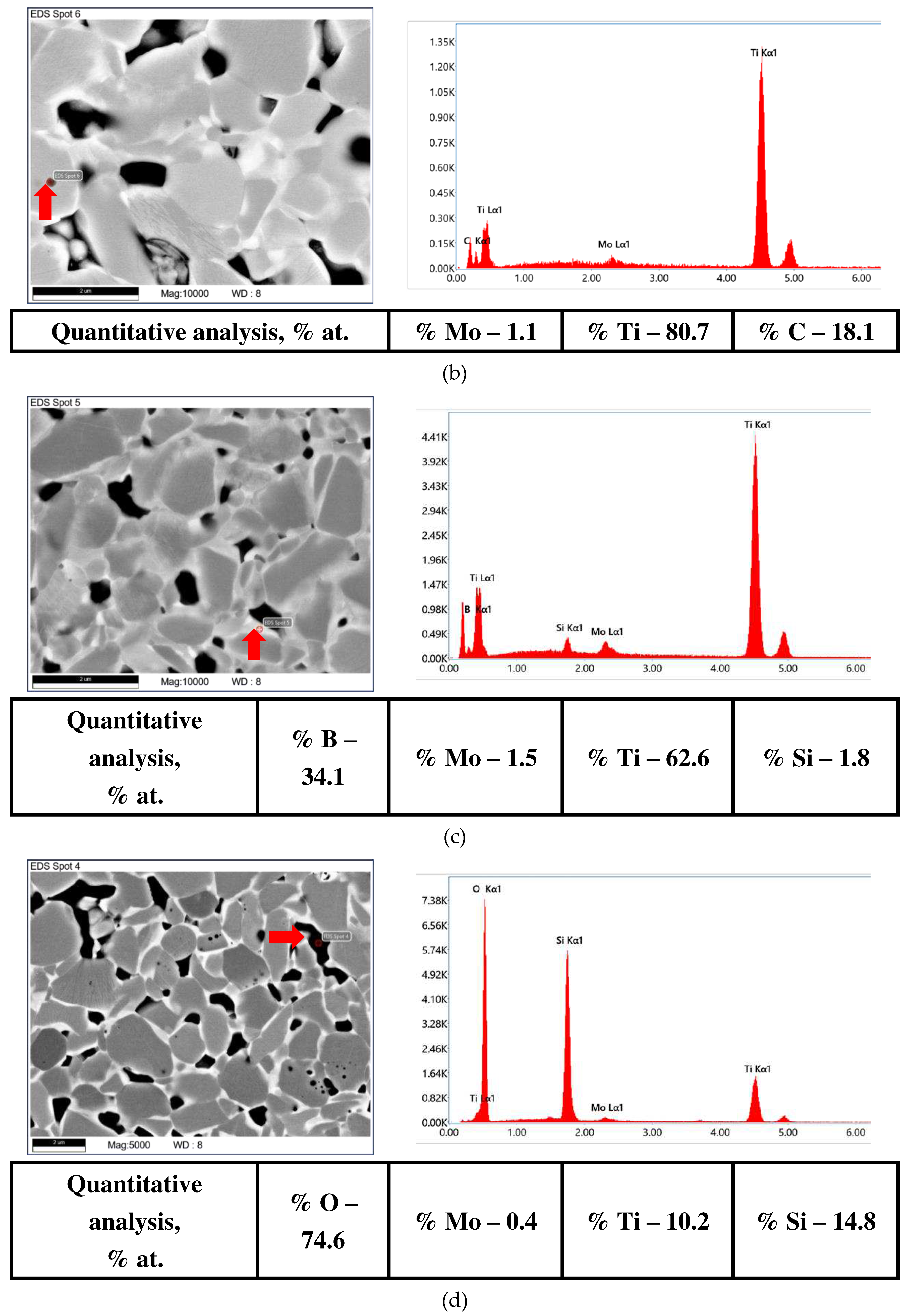
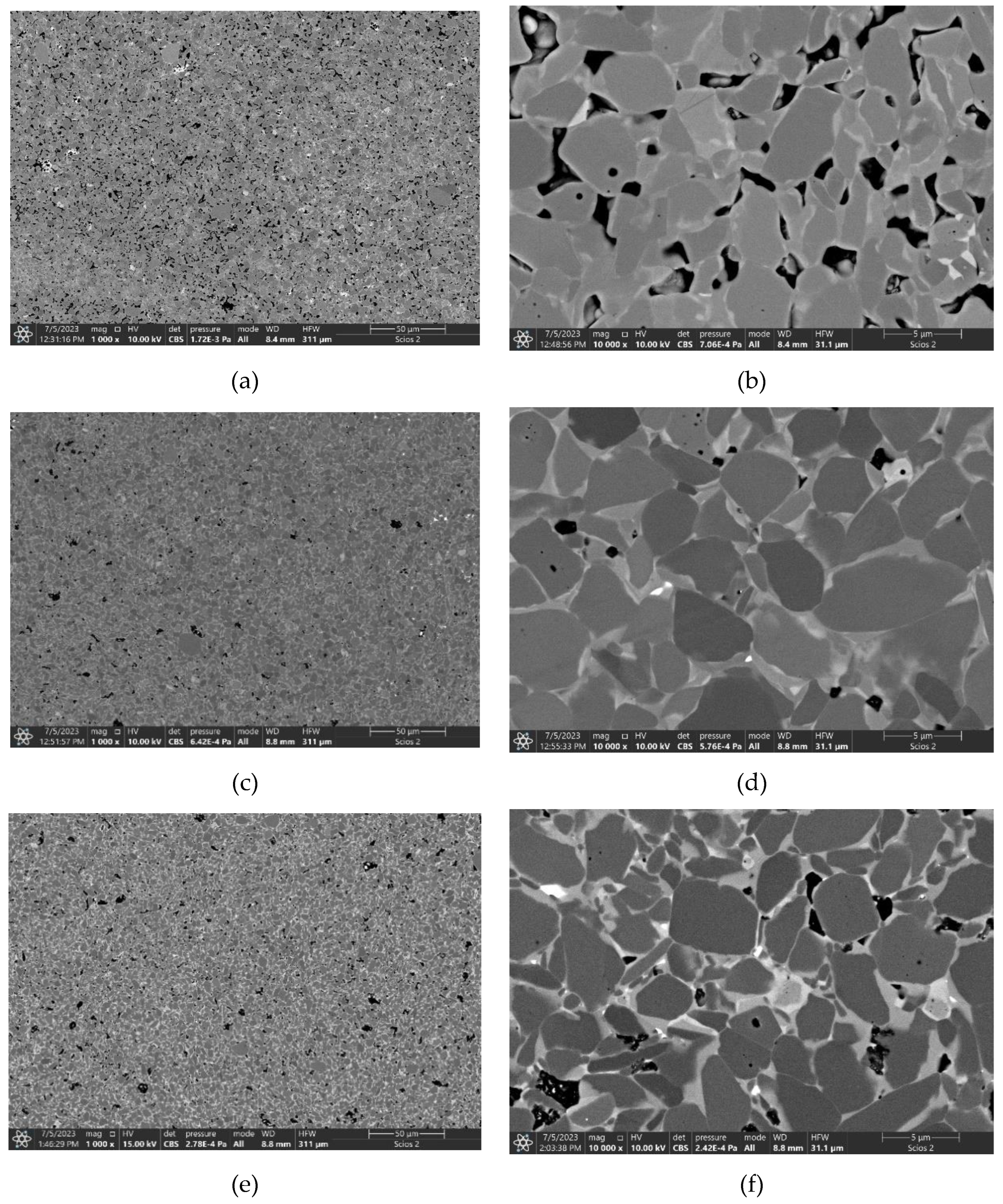
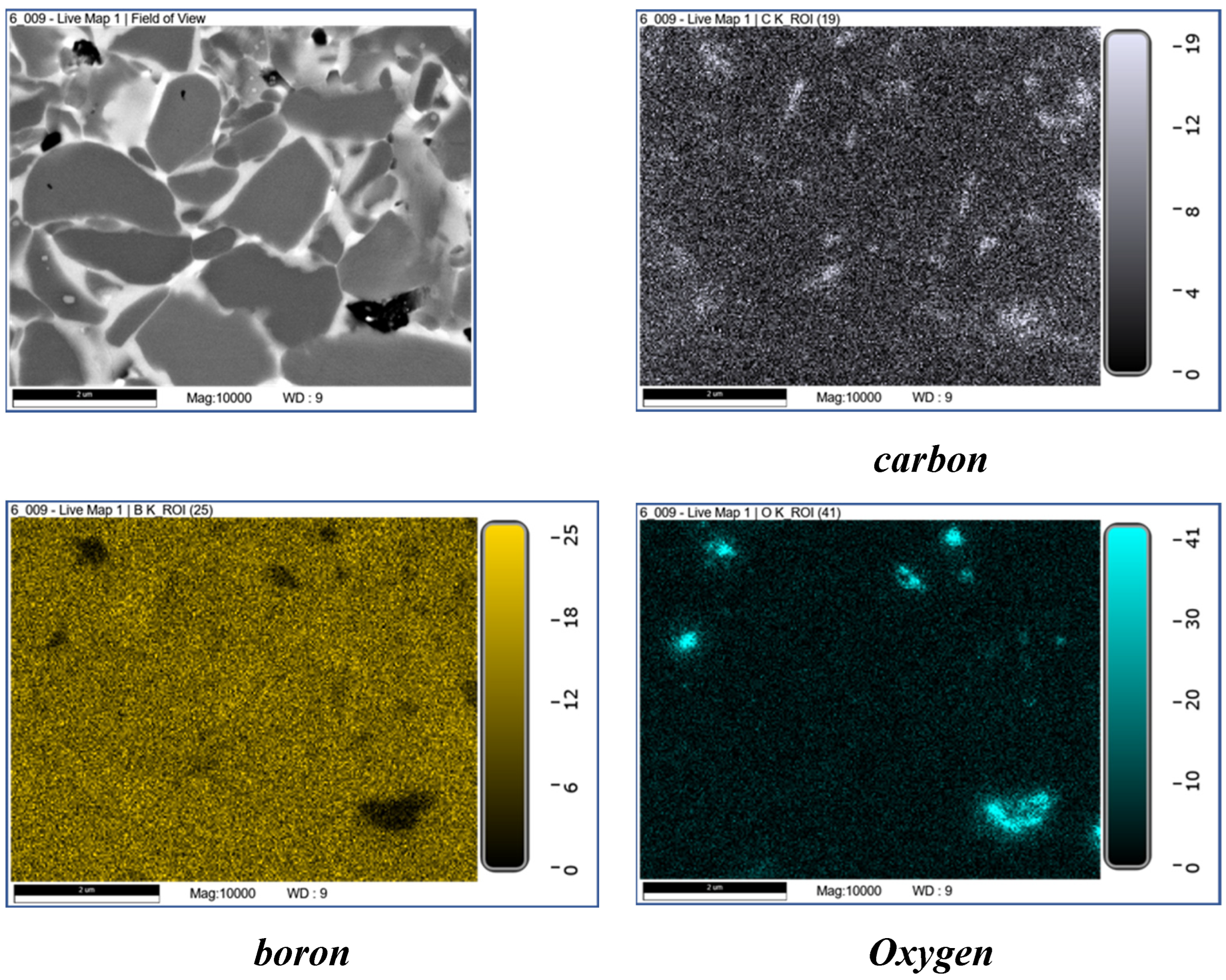
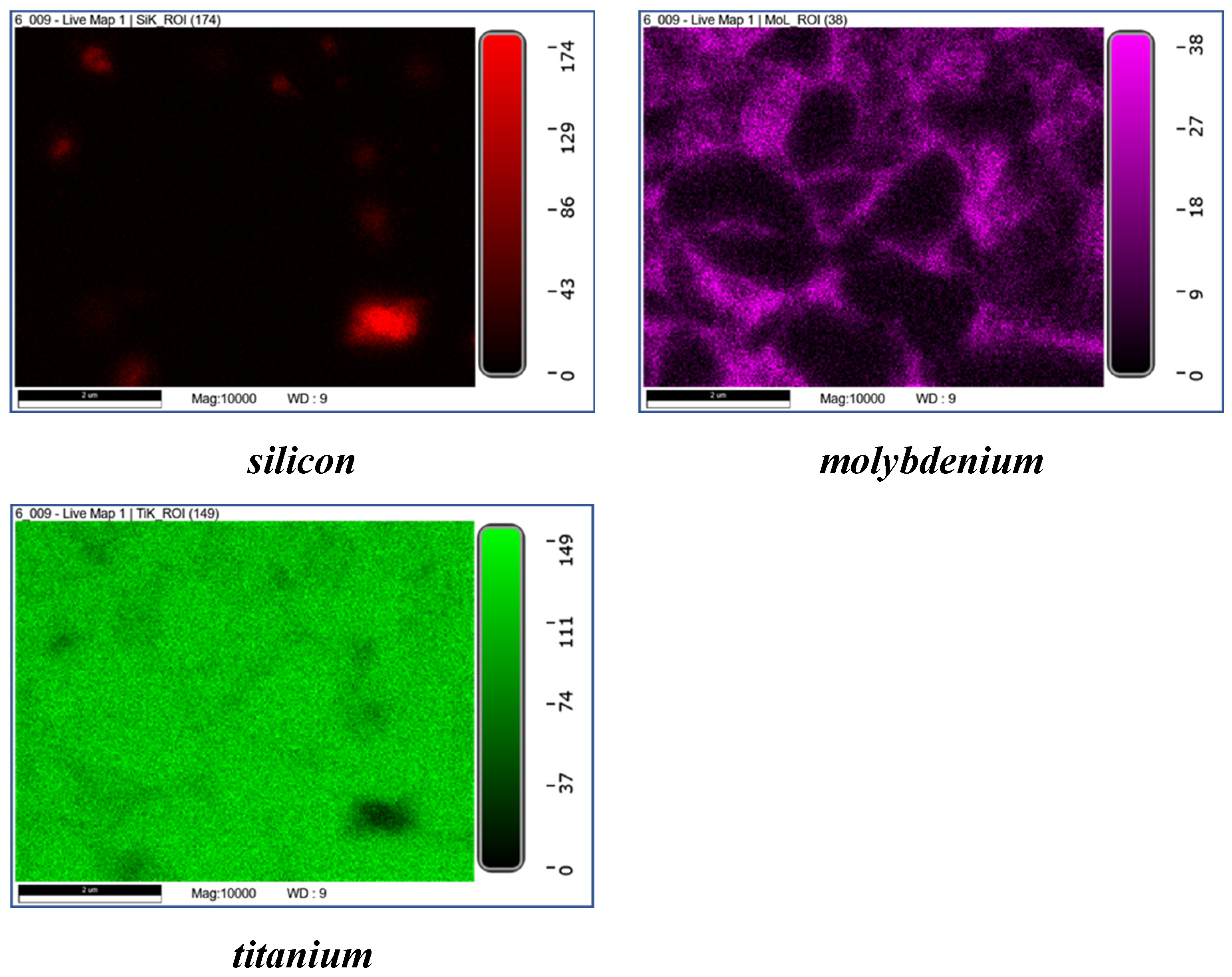
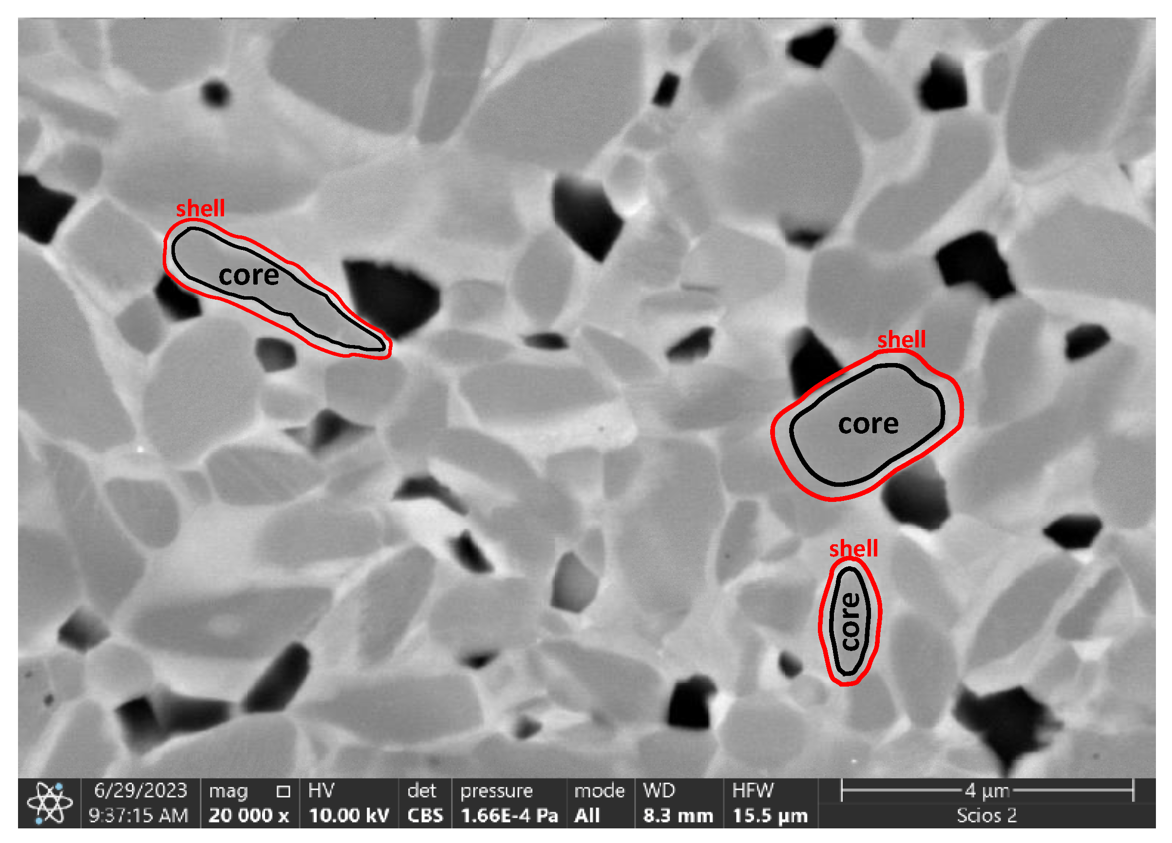
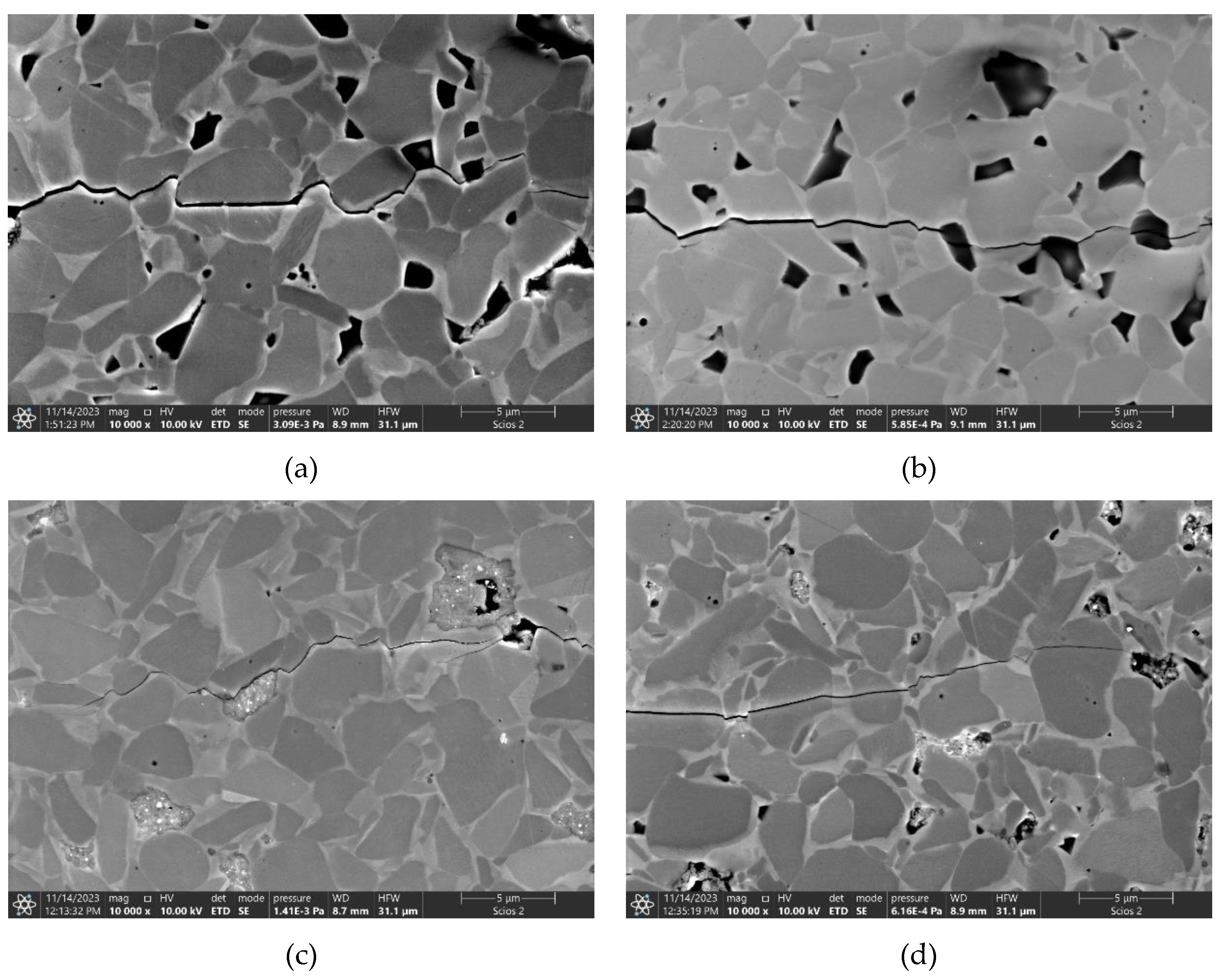
| The initial composition | Name |
|---|---|
| TiB2 | TiB2_0 |
| TiB2+1%C | TiB2_1C |
| TiB2+2%C | TiB2_2C |
| TiB2+3%C | TiB2_3C |
| TiB2+4%C | TiB2_4C |
| TiB2+2.5%MoSi2 | TiB2_2.5MS |
| TiB2+5%MoSi2 | TiB2_5.0MS |
| TiB2+10%MoSi2 | TiB2_10MS |
| TiB2+2%C+2.5%MoSi2 | TiB2_2C_2.5MS |
| TiB2+2%C+5%MoSi2 | TiB2_2C_5.0MS |
| TiB2+2%C+10%MoSi2 | TiB2_2C_10MS |
| Initial phase composition, wt.% | Phase composition of the HP sinters, wt. % |
|---|---|
| 97.5% TiB2, 2.5% MoSi2 | 68.8% TiB2 1, 29.7% TiB2 2, 1.5% MoC |
| 95% TiB2, 5.0% MoSi2 | 69.8% TiB2 1, 28.7% TiB2 2, 1.5% MoC |
| 90% TiB2, 10% MoSi2 | 83.0% TiB2 1, 9.4% TiB2 2, 1.0% MoC, 6.6% MoSi2 |
|
Lattice parameter, Å |
Theoretical unit cell parameters of TiB2, [29] | TiB2+2.5% MoSi2 | TiB2+5.0% MoSi2 | TiB2+10% MoSi2 | |||
|---|---|---|---|---|---|---|---|
| TiB2 1 | TiB2 2 | TiB2 1 | TiB2 2 | TiB2 1 | TiB2 2 | ||
| a | 3.028 | 3.030 | 3.028 | 3.030 | 3.030 | 3.029 | 3.029 |
| b | 3.028 | 3.030 | 3.028 | 3.030 | 3.030 | 3.029 | 3.029 |
| c | 3.228 | 3.230 | 3.230 | 3.230 | 3.231 | 3.231 | 3.230 |
| Initial phase composition, wt.% | Phase composition of the HP sinters, wt.% |
|---|---|
| 95.5% TiB2, 2.0% C, 2.5% MoSi2 | 96.8% TiB2 1, 0.1% TiB2 2, 1.7% TiC, 1.4% SiC |
| 95% TiB2, 2.0% C, 5.0% MoSi2 | 66.3% TiB2 1, 28.9% TiB2 2, 1.8% SiC, 3.0% (Ti,Mo)C2 |
| 90% TiB2, 2.0% C, 10% MoSi2 | 76.1% TiB2 1, 18.6% TiB2 2, 3.1% SiC, 2.2% (Ti,Mo)C2 |
|
Lattice parameter, Å |
Theoretical unit cell parameters of TiB2, [29] |
TiB2+2%C +2.5% MoSi2 |
TiB2+2%C +5.0% MoSi2 |
TiB2+2%C +10% MoSi2 |
|||
|---|---|---|---|---|---|---|---|
| TiB2 1 | TiB2 2 | TiB2 1 | TiB2 2 | TiB2 1 | TiB2 2 | ||
| a | 3.028 | 3.027 | 3.034 | 3.029 | 3.027 | 3.029 | 3.027 |
| b | 3.028 | 3.027 | 3.034 | 3.029 | 3.027 | 3.029 | 3.027 |
| c | 3.228 | 3.233 | 3.220 | 3.230 | 3.231 | 3.230 | 3.232 |
| Sample |
Sintering temperaturę (HP), °C |
Relative density, % *) |
Vickers hardness, GPa |
KIC, MPa·m0.5 |
Young's modulus, GPa |
|---|---|---|---|---|---|
| TiB2_0 | 2150 | 88.2±0.3 | 19.09±6.30 | - | - |
| TiB2_1C | 2150 | 94.3±0.1 | 26.31±5.86 | - | 526±12 |
| TiB2_2C | 2150 | 97.8±0.1 | 25.31±0.77 | 5.16±0.28 | 536±9 |
| TiB2_3C | 2150 | 96.9±0.4 | 23.34±2.17 | 5.26±0.47 | 496±16 |
| TiB2_4C | 2150 | 95.9±0.3 | 25.68±5.29 | 5.52±0.20 | 542±10 |
| TiB2_2.5MS | 1800 | 84.3±0.6 | 16.97±2.86 | - | - |
| TiB2_5.0MS | 1800 | 98.5±0.2 | 26.21±2.25 | 6.25±0.51 | 536±11 |
| TiB2_10MS | 1800 | 100.0±0.4 | 26.78±3.37 | 4.86±0.19 | 504±24 |
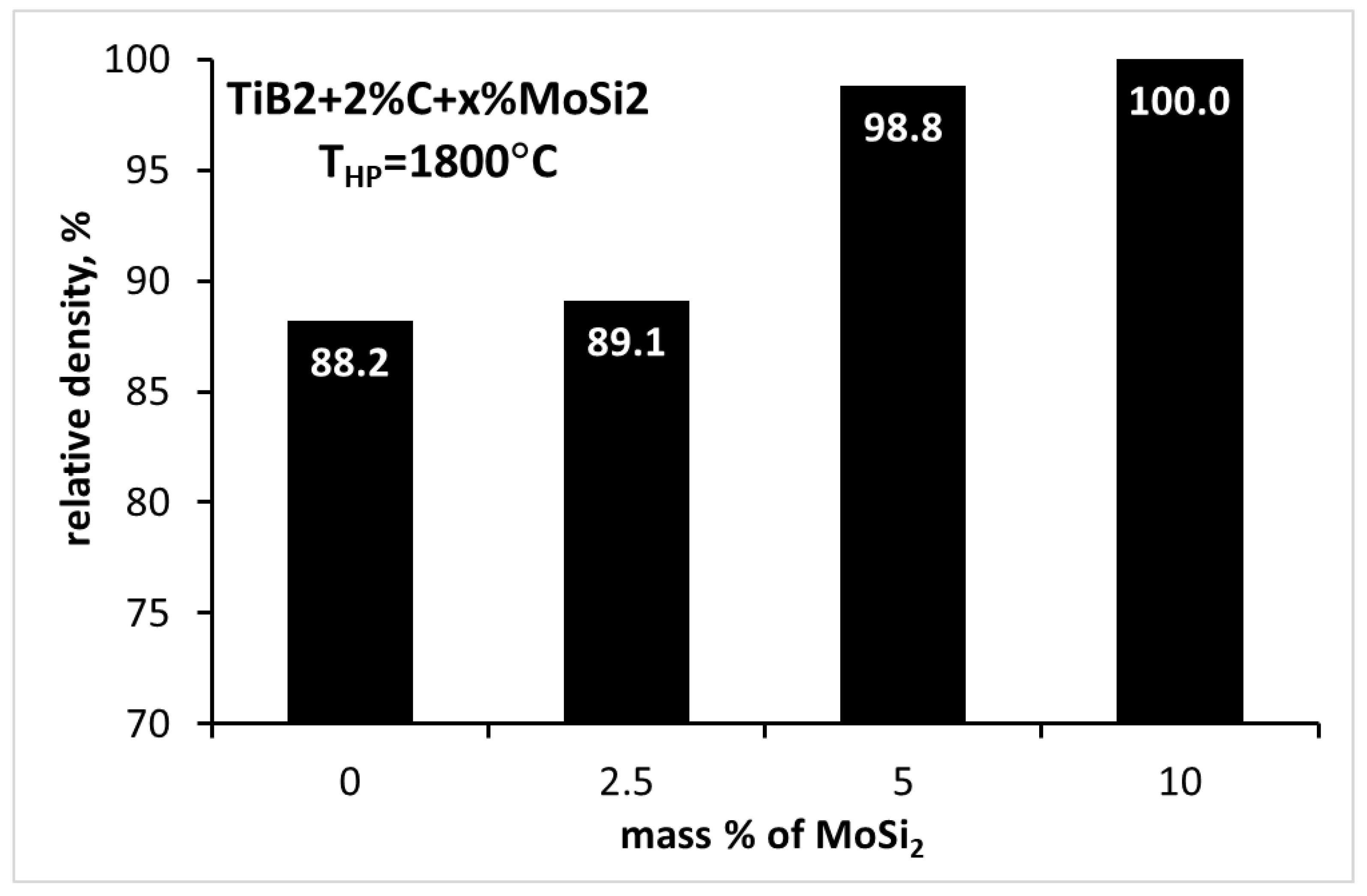
| TiB2_2C_2.5MS | 1800 | 89.1±0.8 | 17.19±1.87 | - | 440±14 |
| TiB2_2C_5.0MS | 1800 | 98.8±0.4 | 24.88±2.03 | 4.79±0.52 | 543±6 |
| TiB2_2C_10MS | 1800 | 100.0±0.2 | 24.41±1.90 | 4.17±0.31 | 533±12 |
| *) the theoretical density of TiB2 was 4.52 g/cm3, | |||||
Disclaimer/Publisher’s Note: The statements, opinions and data contained in all publications are solely those of the individual author(s) and contributor(s) and not of MDPI and/or the editor(s). MDPI and/or the editor(s) disclaim responsibility for any injury to people or property resulting from any ideas, methods, instructions or products referred to in the content. |
© 2023 by the authors. Licensee MDPI, Basel, Switzerland. This article is an open access article distributed under the terms and conditions of the Creative Commons Attribution (CC BY) license (http://creativecommons.org/licenses/by/4.0/).


