Submitted:
27 December 2023
Posted:
29 December 2023
You are already at the latest version
Abstract
Keywords:
1. Introduction
2. Materials and Methods
2.1. Problem Statement and Materials
2.2 Scaffolding Assembly Deficiency Detection System
2.3. Implementation Methods
2.3.1. Deficiency-Recognition Module
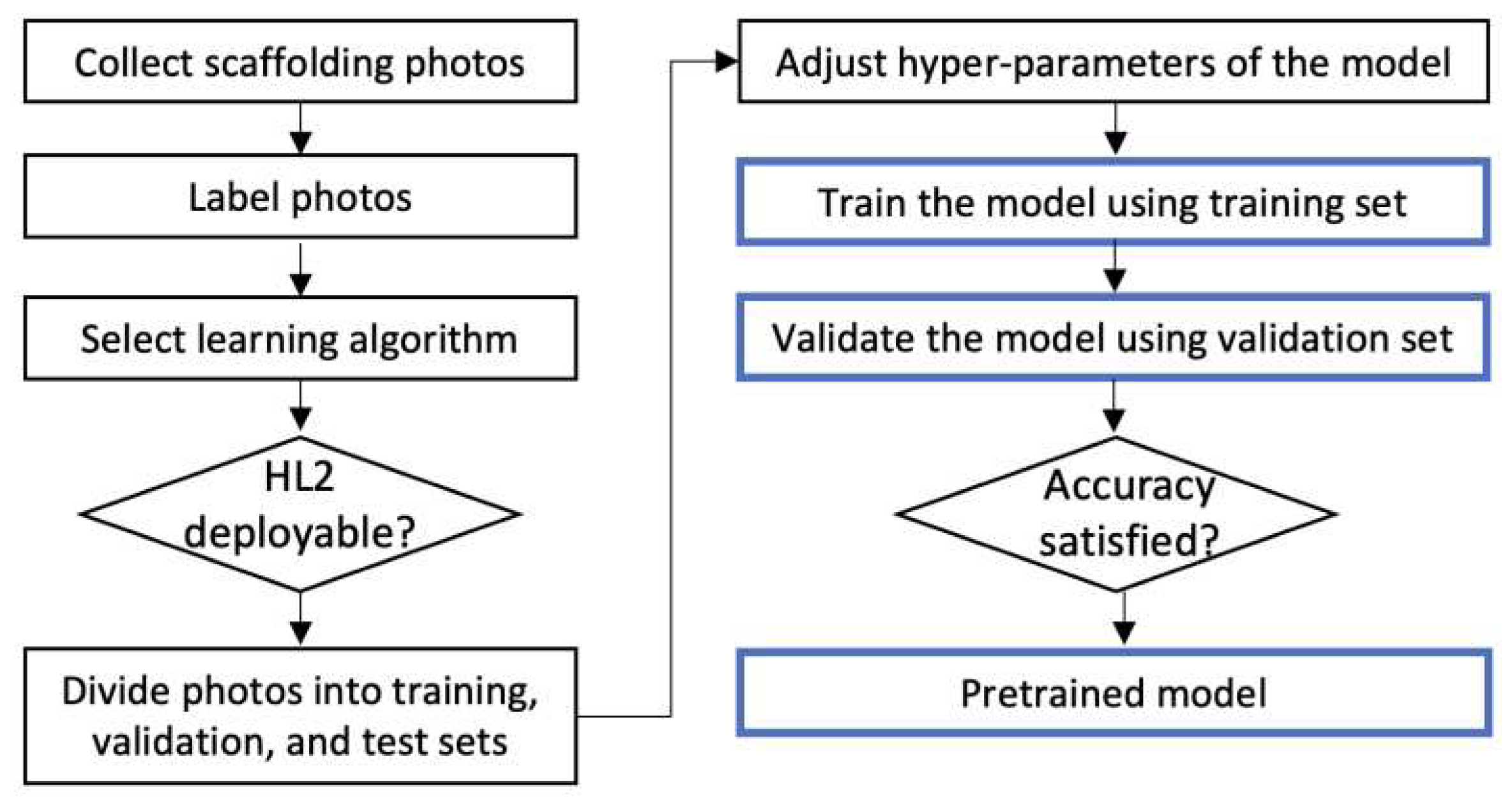
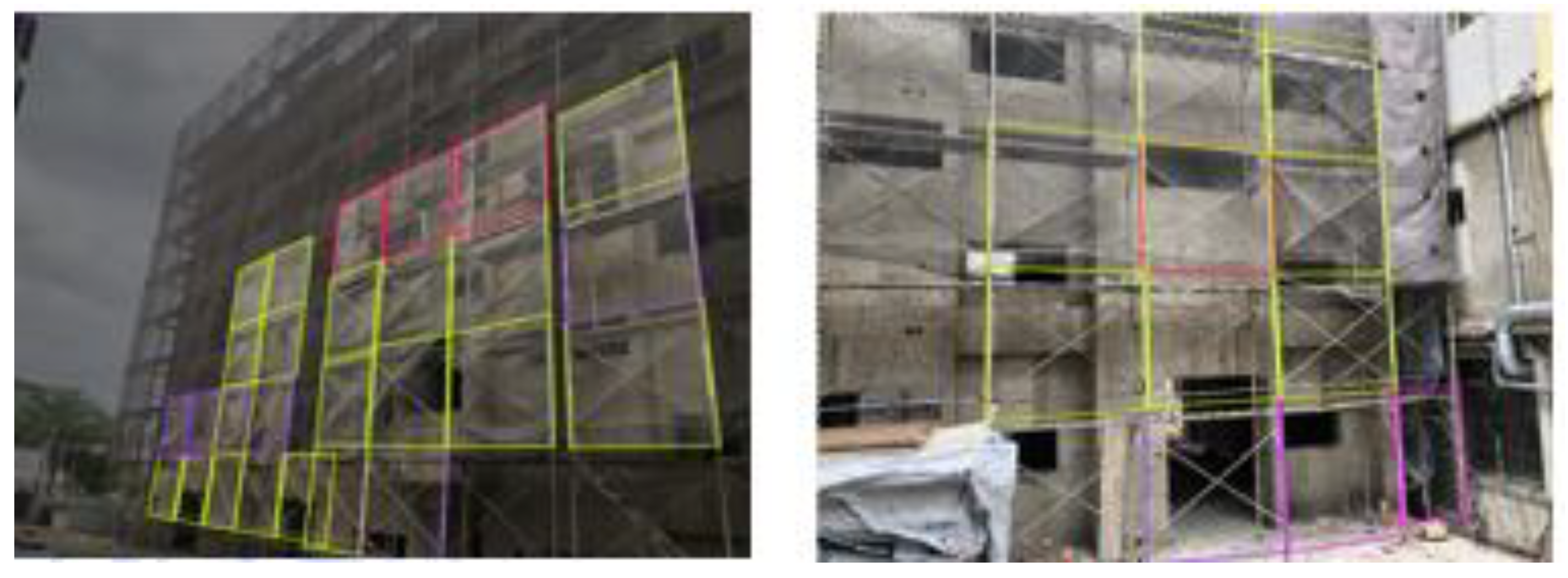
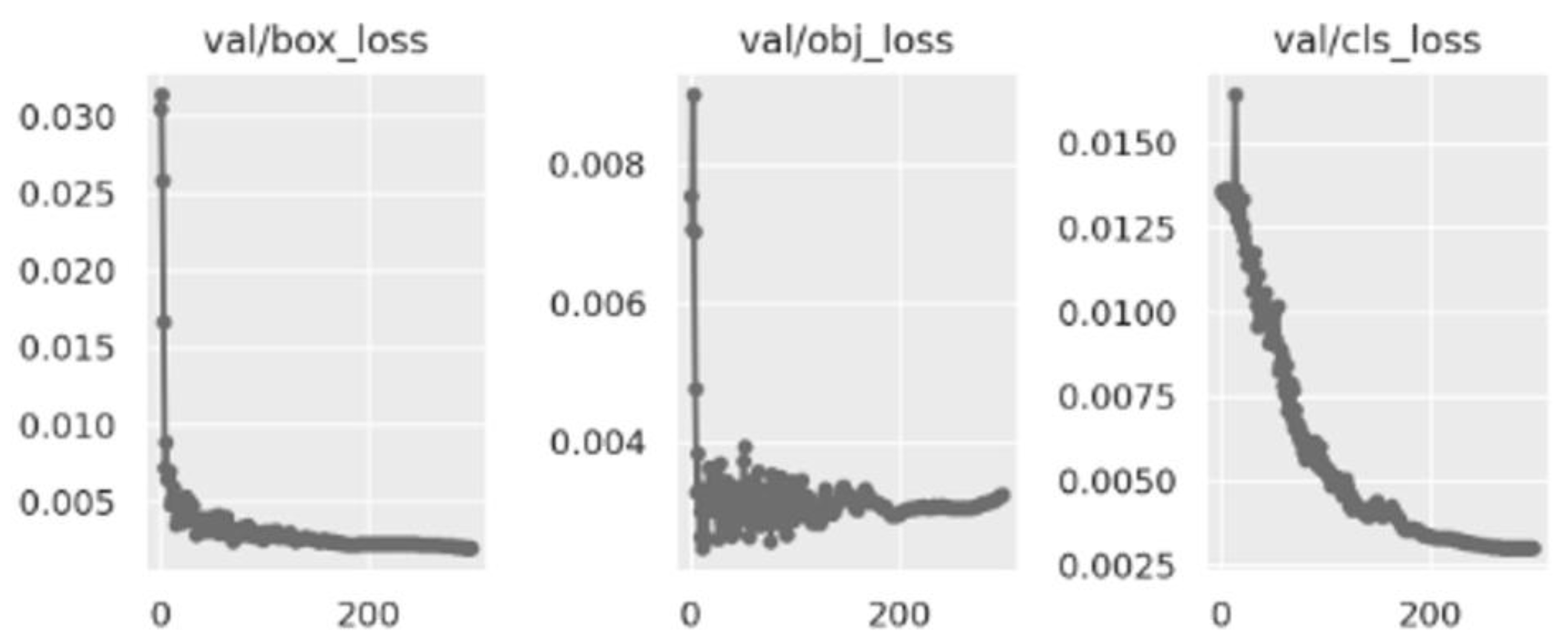

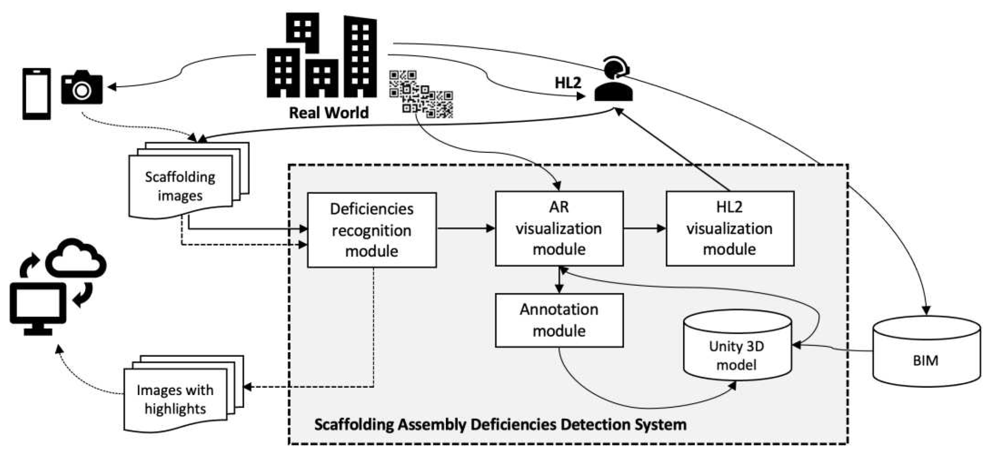
2.3.2. AR Visualization Module
- Step 1: Set up markers
- Step 2: Implement and initialize markers in Unity
- Switch to the Universal Windows Platform setup page by choosing Build Settings/Platform/Universal Windows Platform.
- Setup the initialization parameters by choosing Project Settings/XR Plug-in Management/Windows, and activate Initialize XR on Startup.
- Specify the XR device by choosing Project Settings/XR Plug-in Management/Windows, and activate OpenXR and Microsoft HoloLens feature group.
- Add the mobile control module by adding Object Manipulator Script.
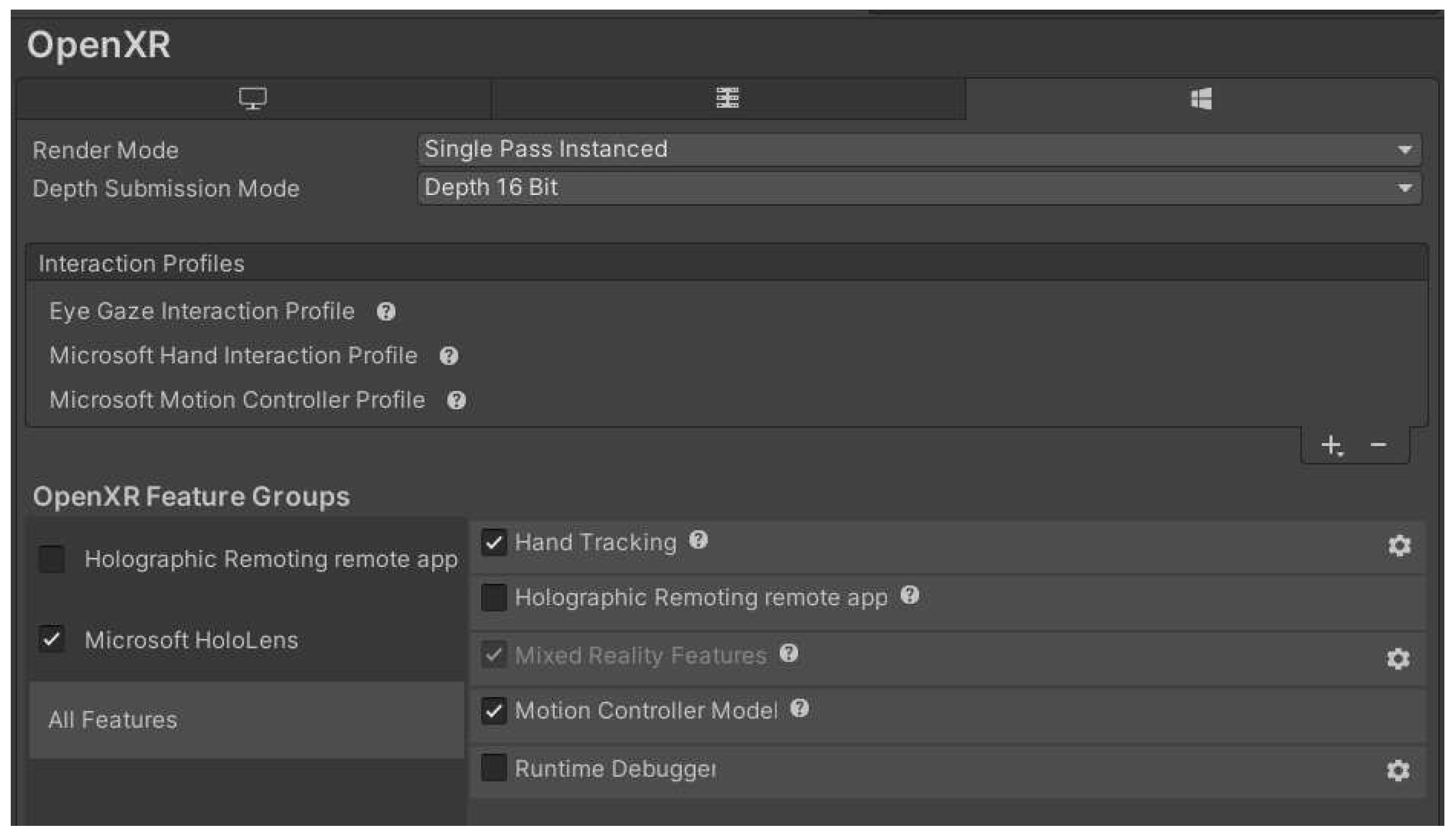
- Add the hand gesture recognition module by choosing Project Settings/OpenXR/Interaction Profiles, and selecting “Eye Gaze Interaction Profile,” “Microsoft Hand Interaction Profile,” and “Microsoft Motion Controller Profile” (Figure 6).
- Activate the hand recognition module by choosing Project Settings/OpenXR/OpenXR Feature Groups and activating Microsoft HoloLens’ “Hand Tracking” and “Motion Controller Model.”
2.3.3. HL2 Visualization Module
3. Results
4. Field Test and Discussion
- The camera shooting angle should be as orthogonal to the target wall face as possible. Nonetheless, the recognition module successfully recognized the deficiencies in some frames sooner or later as the wearer approached those frames. However, because the attached alert frames are always orthogonal squares, the highlights may cause humans to misread the wrong frame. This problem can be avoided so long as the camera shooting angle is orthogonal to the target wall face.
- When shooting at an oblique angle with respect to the target wall face, far away frames may not be recognized by the module owing to self-occlusion. This problem is understandable because even humans cannot evaluate those frames in the same situation, and those frames will be evaluated correctly once the camera moves toward them in the absence of occlusions.
- Considering the practical use case, to enhance work efficiency and inspector’s safety, the tests were performed in front of scaffolds on the ground without actually climbing on the scaffolding boards to efficiently capture multiple frames at a glance. So long as the shooting angle is near orthogonal to the target wall face, an image with 20–50 frames did not seem to be a problem to SADDS. In this way, the use of SADDS is more efficient than inspection with the human eye. Nevertheless, in double-frame scaffold systems, most of the inner frames will not be recognized by the system owing to self-occlusion by the outer frames. Although one may stand on a scaffolding board to shoot the inner frames without occlusion, the number of frames covered in an image would be very limited, and the frames would need to be checked one by one. In such a case, direct inspection with human eyes would be more convenient.
- Before the field test, we were concerned about the system’s ability to recognize “missing cross-tie rod,” which had the least precision (i.e., 0.82 compared to, for example, 0.90 for “missing lower-tie rod”) among the three types of target deficiencies. However, this did not seem to be a problem during the field test. A possible explanation is that in the training test, precision values were calculated per image, and each misidentification was counted. However, during actual field use, images were run as a stream, and when the HL2 wearer was moving, SADDS had many chances to successfully identify deficiencies and, eventually, alert the wearer.
- The scaffolds at both test sites were enclosed by safety nets (e.g., anti-fall or dustproof nets), which did not affect the recognition accuracy of SADDS so long as human eyes could see through the net. Indeed, in the presence of safety nets, it was more difficult for humans to recognize unqualified assemblies from a distance than it was for SADDS.
5. Conclusions
Funding
Conflicts of Interest
References
- Li, S.; Gu, X.; Xu, X.; Xu, D.; Zhang, T.; Liu, Z.; Dong, Q. Detection of concealed cracks from ground penetrating radar images based on deep learning algorithm. Construction and Building Materials 2021, 273, 121949. [Google Scholar] [CrossRef]
- Fang, W.; Ding, L.; Zhong, B.; Love, P.E.; Luo, H. Automated detection of workers and heavy equipment on construction sites: a convolutional neural network approach. Advanced Engr. Informatics 2018, 37, 139–149. [Google Scholar] [CrossRef]
- Reja, V.K.; Varghese, K.; Ha, Q.P. Computer vision-based construction progress monitoring. Automation in Construction 2022, 138, 104245. [Google Scholar] [CrossRef]
- Shanti, M.Z.; Cho, C.S.; Byon, Y.J.; Yeun, C.Y. A novel implementation of an AI-based Smart construction safety inspection protocol in the UAE. IEEE Access 2021, 9, 166603–166616. [Google Scholar] [CrossRef]
- Park, S.E.; Eem, S.H.; Jeon, H. Concrete crack detection and quantification using deep learning and structured light. Construction and Building Materials 2020, 252, 119096. [Google Scholar] [CrossRef]
- Microsoft (2023). “HoloLens 2 release notes,” https://learn.microsoft.com/en-us/hololens/hololens-release-notes#about-hololens-releases, last updated on 10/11/2023.
- Leite, F.; Cho, Y.; Behzadan, A.H.; Lee, S.H.; Choe, S.; Fang, Y.; Akhavian, R.; Hwang, S. Visualization, information modeling, and simulation: grand challenges in the construction industry. Journal of Computing in Civil Engineering 2016, 30. [Google Scholar] [CrossRef]
- Park, S.; Bokijonov, S.; Choi, Y. Review of Microsoft HoloLens applications over the past five years. Applied Sciences 2020, 11, 7259. [Google Scholar] [CrossRef]
- Pratt, P.; Ives, M.; Lawton, G.; et al. Through the HoloLens looking glass: augmented reality for extremity reconstruction surgery using 3D vascular models with perforating vessels. Eur. Radiol. Exp. 2018, 2, 2. [Google Scholar] [CrossRef] [PubMed]
- Al-Maeeni, S.S.H.; Kuhnhen, C.; Engel, B.; Schiller, M. Smart retrofitting of machine tools in the context of industry 4.0. Procedia CIRP 2019, 88, 369–374. [Google Scholar] [CrossRef]
- Hübner, P.; Clintworth, K.; Liu, Q.; Weinmann, M.; Wursthorn, S. Evaluation of HoloLens tracking and depth sensing for indoor mapping applications. Sensors 2020, 20, 1021. [Google Scholar] [CrossRef] [PubMed]
- Wu, M.; Dai, S.-L.; Yang, C. Mixed reality enhanced user interactive path planning for omnidirectional mobile robot. Appl. Sci. 2020, 10, 1135. [Google Scholar] [CrossRef]
- Mourtzis, D.; Siatras, V.; Zogopoulos, V. Augmented reality visualization of production scheduling and monitoring. Procedia CIRP 2020, 88, 151–156. [Google Scholar] [CrossRef]
- Moezzi, R.; Krcmarik, D.; Hlava, J.; Cýrus, J. Hybrid SLAM modeling of autonomous robot with augmented reality device. Mater. Today Proc. 2020, 32, 103–107. [Google Scholar] [CrossRef]
- Karaaslan, E.; Bagci, U.; Catbas, F.N. Artificial intelligence assisted infrastructure assessment using mixed reality systems. Transportation Research Record 2019, 2673, 413–424. [Google Scholar] [CrossRef]
- Sanni-Anibire, M.O.; Salami, B.A.; Muili, N. A framework for the safe use of bamboo scaffolding in the Nigerian construction industry. Safety Science 2022, 151, 105725. [Google Scholar] [CrossRef]
- Baek, C.W.; Lee, D.Y.; Park, C. S. Blockchain based Framework for Verifying the Adequacy of Scaffolding Installation. In Proc. of the 37th ISARC (Int. Symposium on Automation and Robotics in Construction), Vol. 37, pp. 425-432, 2020, Kitakyushu, Japan, IAARC Publications.
- Sakhakarmi, S.; Park, J.W.; Cho, C. Enhanced machine learning classification accuracy for scaffolding safety using increased features. Journal of Construction Engineering and Management 2019, 145, 04018133. [Google Scholar] [CrossRef]
- Choa, C.; Sakhakarmi, S.; Kim, K.; Park, J.W. Scaffolding Modeling for Real-time Monitoring Using a Strain Sensing Approach. In Proc. of 35th ISARC (Int. Symposium on Automation and Robotics in Construction), Berlin, Germany, 2018, pp. 48-55. [CrossRef]
- Ministry of Labor of Taiwan, Safety Regulations for Inspecting Construction Scaffolding. https://laws.mol.gov.tw/FLAW/FLAWDAT01.aspx?id=FL083843 (in Chinese), 2018.
- Roboflow, Inc. (2023), roboflow official site, https://roboflow.com/.
- He, K.; Gkioxari, G.; Dollár, P.; Girshick, R. Mask R-CNN. In Proc. of 2017 IEEE International Conference on Computer Vision (ICCV), Venice, Italy, 2017, pp. 2980-2988. [CrossRef]
- Jocher, G.; Stoken, A.; Borovec, J.; NanoCode012; ChristopherSTAN; Changyu, L.; Laughing, tkianai, yxNONG, Hogan, A., et al. (2021). “Ultralytics/yolov5: v4.0 – nn.SiLU() activations, weights & biases logging, PyTorch hub integration,”. [CrossRef]
- PTC, “Vuforia Engine Developer’s Portal”(2023), ‘https://developer.vuforia.com/.
- Unity (2023), “Vuforia Hololens 2 Sample”, https://assetstore.unity.com/packages/templates/packs/vuforia-hololens-2-sample-101553.
- Microsoft Inc. (2023) ‘GitHub Copilot and Visual Studio 2022’, https://visualstudio.microsoft.com/zh-hant/.


| Qualified | Missing cross-tie rod | Missing lower-tie rod | Missing footboard |
|---|---|---|---|
 |
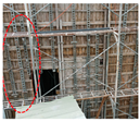 |
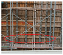 |
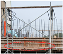 |
 |
 |
 |
 |
| green (763) | magenta (245) | purple (575) | red (643) |
| mAP | Qualified | Missing cross-tie rod | Missing lower-tie rod | Missing footboard | |
|---|---|---|---|---|---|
| Validation | 0.94 | 0.97 | 0.96 | 0.937 | 0.93 |
| Test | 0.88 | 0.95 | 0.80 | 0.90 | 0.88 |
| mAP | Qualified | Missing cross-tie rod | Missing lower-tie rod | Missing footboard | |
|---|---|---|---|---|---|
| Validation | 0.96 | 0.98 | 0.979 | 0.90 | 0.96 |
| Test | 0.89 | 0.96 | 0.82 | 0.90 | 0.89 |
| Box loss | Object loss | Class loss | |
|---|---|---|---|
| Validation | 0.0020 | 0.0032 | 0.0030 |
| Test | 0.0021 | 0.0041 | 0.0037 |
Disclaimer/Publisher’s Note: The statements, opinions and data contained in all publications are solely those of the individual author(s) and contributor(s) and not of MDPI and/or the editor(s). MDPI and/or the editor(s) disclaim responsibility for any injury to people or property resulting from any ideas, methods, instructions or products referred to in the content. |
© 2023 by the authors. Licensee MDPI, Basel, Switzerland. This article is an open access article distributed under the terms and conditions of the Creative Commons Attribution (CC BY) license (http://creativecommons.org/licenses/by/4.0/).


