1. Introduction
European plastic production in 2021 reached the 57.2Mt, where 87.6% of them were fossil-based polymers, 10.1% recycled polymers, also from fossil resources, and only 2.3% were biobased polymers. France and Spain are the 3rd and 4th plastic consumers in Europe with 16.9% of the European production. [
1]. Although the use of plastic materials in agriculture and gardening is reduced (3.1%) in comparison to other fields such as packaging (39.1%), plastic materials in agriculture are generally for single-use as the use conditions degrade the materials, being impossible to reuse and recycle them appropriately. In some cases, its recollection is also problematic. Thus, the use of these materials contributes to a huge problem of plastic materials in the environment [
2]. However, plastics have contributed positively to the development of agriculture and, nowadays, they are irreplaceable materials in the field.
Biodegradable and biobased materials are replacing common plastic materials in applications such as packaging, and could become promising alternative also in the agricultural sector [
3]. Actually, it is possible to find bioplastic materials commercially available in agriculture for short-time applications. It is due to their biodegradable behavior that decreases rapidly their dimensional stability [
4,
5]. One of these materials are polyhydroxyalkanoates (PHA), where polyhydroxy-3-butyrate (PHB) is the most often studied one [
6,
7]. PHA are biopolyesters produced from bacteria and can be easily biodegraded. However, PHA, and mainly PHB, are still highly expensive as their production methodology still needs to be optimized [
8,
9]. Additionally, although its properties are competitive against polyethylene (PE) and polypropylene (PP), the easy degradation of PHB reduces drastically its stability [
10]. To enlarge the lifespan of PHB-based products while maintaining the biodegradability of them and reducing the cost of PHB materials, the reinforcement of this polymer with natural fibres has been studied [
11,
12].
Cellulose and lignocellulosic fibres have been commonly used as reinforcement in polymer composite materials [
13]. Although their mechanical properties are lower than those of other fibres such as glass fibres or carbon fibres, the effect could be solved by adding a higher fibre content to the material. Moreover, their renewable and biode-gradable characters have demonstrated their potential to be considered as green rein-forcements [
14]. In addition, the lower stiffness and fragility of this reinforcement, that allows its recyclability in composite materials, create a lower damage in the processing equipments. Therefore, reinforcing PHB with lignocellulosic fibres could reduce the cost of the materials while enlarging their lifespan without attempting the biodegradable properties of PHB [
15]. However, the reinforcing effect of the fibres is related to their capacity to establish and interact with the polymer matrix. PHB is a linear polyester with a limited interaction with cellulose, like PLA-based reinforced composites [
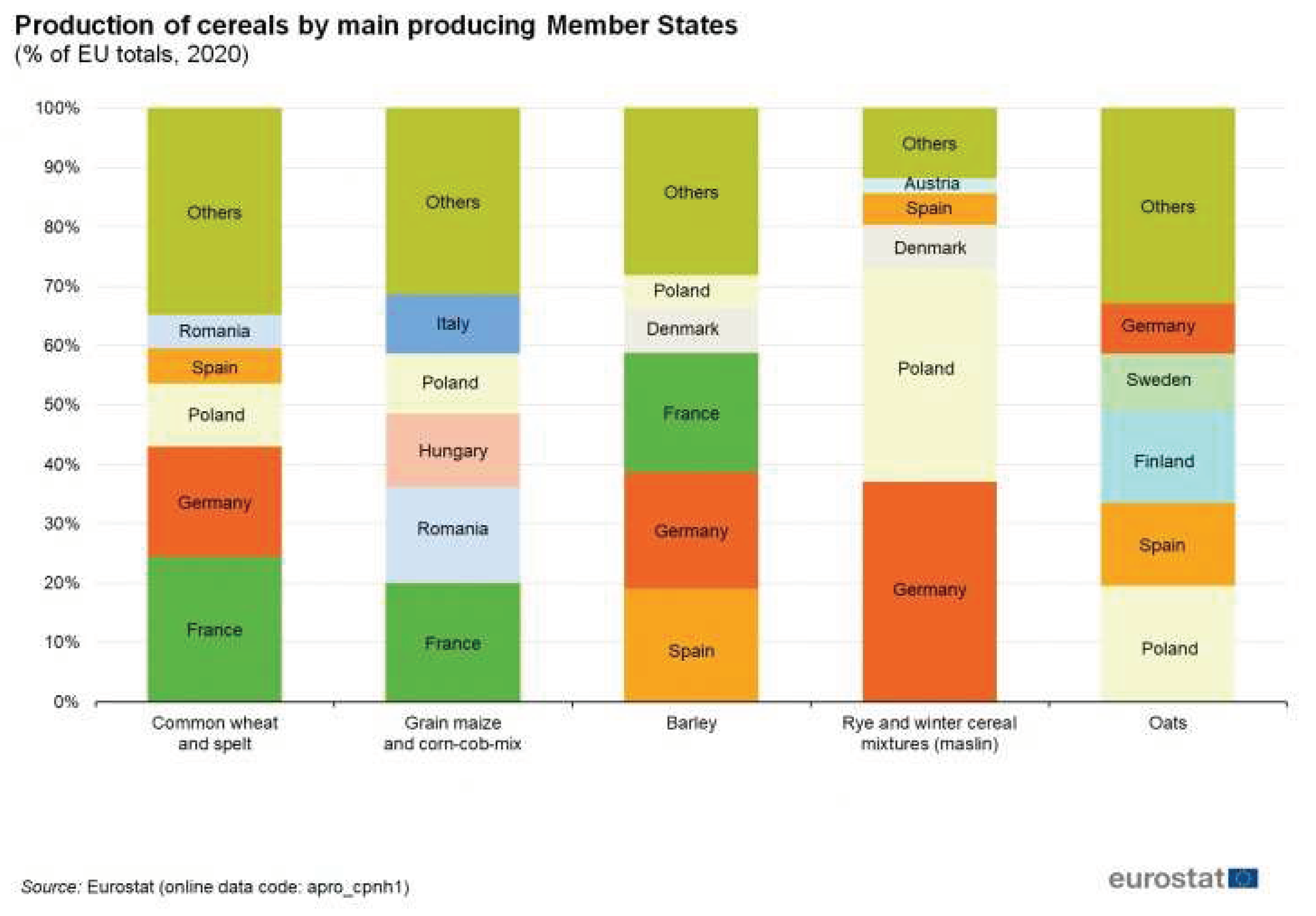
16]. Cellulose is the main chemical compound in lignocellulosic fibres but its molecular weight, arrangement or crystallinity depend on the natural resources, being its selection and treatment a key point. It is well known that wood and filament fibres show better mechanical properties, enlarging the reinforcement effect in polymer composites, but at a high price. Agriculture residues have become a greener alternative to these fibres, unexpansive but with low profit. France and Spain are two of the highest barley producers in the European Union (
Figure 1) and, consequently, both countries have a large residue (i.e., the straw) available from their harvest [
17]. In this sense, the European project BIOPLAST considered the barley straw as a source of mechanical reinforcement for PHB [
18], with the main goal of producing fully biobased and biodegradable composite materials for agriculture.
In this work, the production and characterization of PHB-based composite materials reinforced with barley straw, and their performance in a real product for agriculture will be analysed. The agriculture residue from barley will be treated with different physical and chemical treatments to study the wettability of fibres with the PHB matrix. As mentioned above, the interaction of cellulose with the polymer matrix is indispensable. It is affected by the type of fibre used [
13,
19]. Barley straw has less lignin content than wood fibres, but a larger amount of extractives (i.e., minerals, waxes, fatty acids, proteins, free sugars or flavonoids). Although these components could enhance the dispersion of fibres in the PHB matrix, the stress transmission could be reduced as these components are inhibiting the interaction with cellulose as it has been observed in other polyesters [
16]. In order to evaluate the viability of these composite materials, they will be produced not only according to a discontinuous process but also to a continuous one, and an economic study will be carried out. Finally, an injection product, i.e., a flowerpot, will be simulated and compared to those produced from common plastics to demonstrate the suitability of these PHB-based composites to replace petrol-based materials.
2. Materials and Methods
2.1. Materials
A Polyhydroxy-3-butyrate (PHB) Biomer, grade P209, supplied by Biomer (Schwalbach, Germany) was used as the polymer matrix for the formulation of com-posites. Barley straws were kindly provided by farmers from the region on the border between Spain and France.
2.2. Fibre Preparation
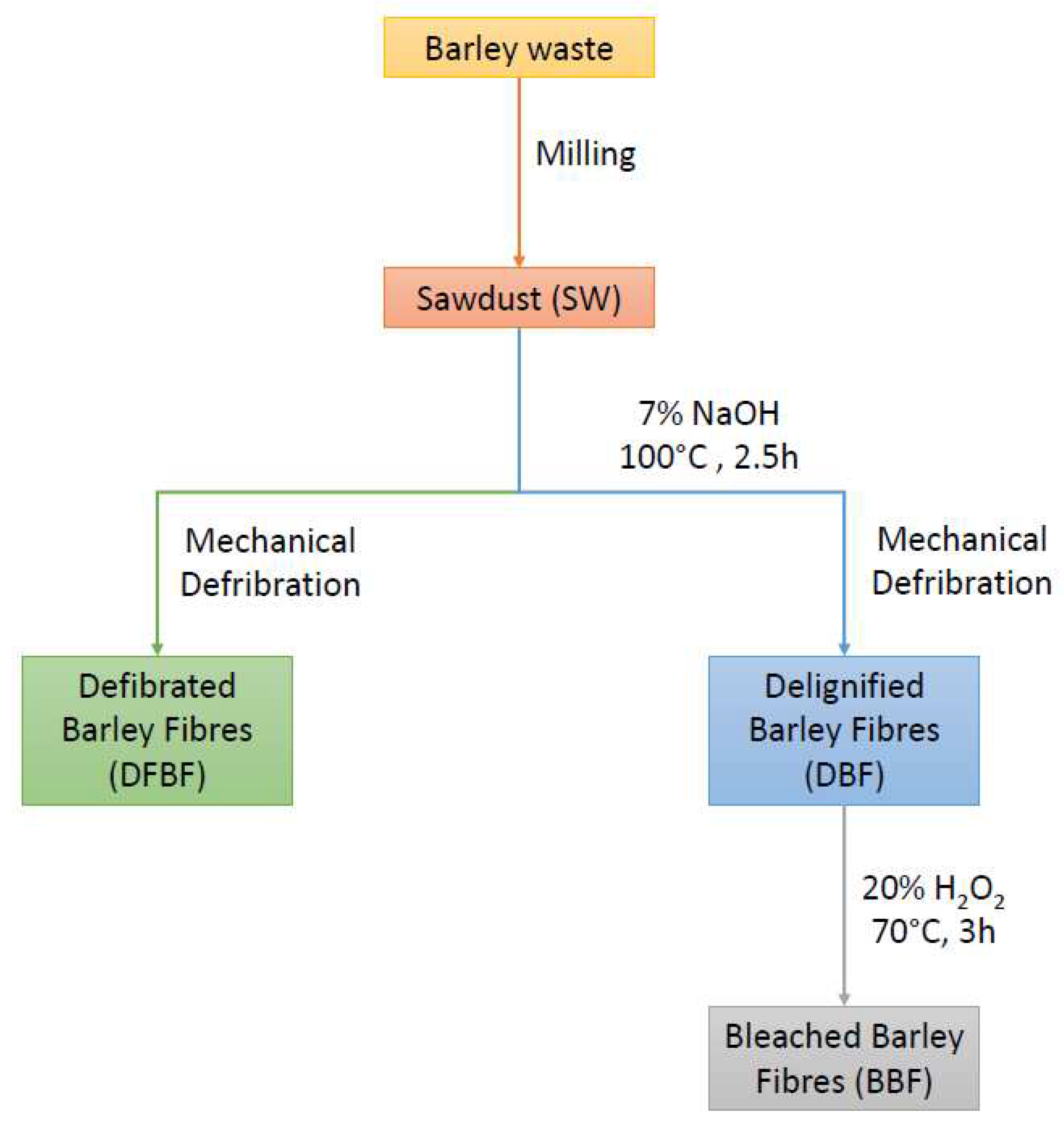
Four different processed fibres were used as reinforcement for the composite ma-terials to evaluate the effect of the chemical composition and morphology in the com-posite properties: sawdust (SW); defibred (DFBF); delignified (DBF); and bleached (BBF) fibres. The different treatments were performed to assess the effects of the chemical composition and morphology of the fibres on itsthe composite’s mechanical performance. The bBarley straw was cleaned, dried and ground in a 5 mm sieve to obtain the sawdust (SW). For defibred fibres (DFBF), the sawdust was passed through a Sprout-Waldron mill (Sprout Waldron, Muncy PA) to correctly separate the fibres from each other. This mechanical process only defibrates the barley fibrous residue to obtain individualized fibres without affecting the chemical composition of the barley straw as it can be pro-duced in other cold water-assisted mechanical processes [
20]. Delignified fibres (DBF) were obtained by ambient digestion of the sawdust in a reactor at 100ºC 100°C for 2.5 h with NaOH. NaOH concentration was 7% (w/w of fibres), and the consistency of the cooking process was 10% [
21,
22]. Afterwards, the fibres were cleaned with distilled water until neutral pH, and passed through the Sprout-Waldron mill to obtain indi-vidualized fibres. Finally, bleached fibres (BBF) were obtained from the DBF delignified fibres. These fibres were submitted to a bleaching process with hydrogen peroxide (H2O2) [
23]. The treatment was carried out at 70ºC70°C, with a consistency of 3% and for 3 h. The H2O2 concentration was 20% (w/w of fibres), and it was added every 40 min until the 3 h were completed. The production of the different reinforcements is summarized in
Figure 2.
2.3. Fibre Chemical Composition and Morphological Analysis
Fibre’s chemical composition was analysed following the TAPPI standards: ashes (T211), extractives (T204), and soluble lignin (T222). The holocellulose content, re-ferred as cellulose and hemicelluloses content, was obtained from the difference in the total with the other components.
The morphological analysis of the fibres was carried out in a MorFi fibre analyser (Techpap, Grenoble, France) using an aqueous suspension of 25 mg/L of fibres. Optical microscopy photographs were obtained at ×20 magnification with a laboratory micro-scope.
2.4. Composite Compounding and Samples Obtaining (Discontinuous Production)
PHB-based composite materials with the different reinforcing fibres were pre-pared in a Gelimat kinetic mixer (Draiswerke, Mahwah, New Jersey, USA). The rein-forcement contents for each formulation were 10, 20 and 30%. Previous to the blend production, fibres and PHB were dried in a ventilated oven at 80°C. The fibres and PHB matrix were slowly added in the mixing chamber of the Gelimat at low speed (300 rpm). Then, the chamber was closed, and the mixing rate was increased up to 2500 rpm. Once the polymer matrix was blended with the barley fibres, the chamber was opened, and the obtained material was cooled down and ground for its subsequent transformation. The specimens for the mechanical testing were prepared by injection moulding using an Allrounder-220M injection moulding equipment (Arburg, Eschweiler, Germany). A decreasing temperature profile, 160-165-163-160°C, was used for its transformation to avoid PHB degradation. The pressure in the volumetric phase ranged from 300 to 400 bars for the composites with higher fibre content, and it was 37 bars for the maintaining pressure phase.
2.5. Process Intensification
PHB/SW and PHB/DFBF (90/10 (w/w) and 70/30 (w/w)) composite materials were also prepared continuously using a Clextral Evolum 25 twin-screw extruder (Firminy, France). First, SW and DFBF were dried overnight at 80°C. Their moisture contents were 3.5% at the time of compounding. Ten successive modules composed the extruder barrel with a total length (L) of 1 m, and a L/D ratio of 40, with D (25 mm) corre-sponding to the screw diameter. A Schenck Process ProFlex C 500 gravimetric feeder (Darmstadt, Germany) was used for introducing PHB in the first module. A Coperion K-Tron K-CL KT20 volumetric feeder (Stuttgart, Germany) was used for dosing SW and DFBF. They were then conveyed using a side feeder at the level of the fifth module.
The screw profile used was as follows:
-Melting of PHB in the fourth module was performed thanks to the use of two series of bilobe paddles and a series of reverse screw elements, all three joined to-gether.
-Dispersion of fibres in the PHB molten matrix was reached using three suc-cessive zones of bilobe paddles in modules 6 to 8. The second kneading block was com-pleted by reverse screw elements immediately after.
-Degassing was implemented at the level of the ninth module.
Similar to the injection-moulding process, the temperature profile was chosen to reduce as much as possible the PHB thermal degradation, and it was as follows (from modules 1 to 10, and at the die): 60-170-175-180-175-175-170-165-160-155-155°C (die). Screw rotation speed (SS, rpm) and total feed rate (Q, kg/h) were set at 200 rpm and 10 kg/h, respectively. As a continuation of the final module, a die made of two holes, each 3 mm in diameter, was positioned. After cooling in a water-cooled channel, the two rods were granulated. The strand pelletizer used was a Maag Automatik GmbH PRI-MO 120 E device (Großostheim, Germany).
From the PHB/SW and PHB/DFBF composite materials, test specimens were pre-pared by injection moulding using a Negri Bossi VE 160-720 press (Cologno Monzese, MI, Italy). From the composite materials filled with 30% (w/w) fibres, flowerpots were also manufactured as an example of real product. Thus, two different moulds were used. For the injection of the test specimens, one tensile specimen and one flexural specimen were simultaneously obtained (i.e., two-cavity mould). For that of the flow-erpots, only one pot was produced per cycle (i.e., one-cavity mould). The temperature profile along the plasticizing screw was 150-160-180°C, and that of the nozzle was 140°C. The screw speed and counter-pressure were 100 rpm and 5 bars, respectively. The injection speed and follow-up pressure were 150 mm/s and 700 bars, respectively. The clamping force was always 1600 kN. The mould temperature and cooling duration were 30°C and 30 s, respectively.
2.6. Mechanical Testing
PHB-based composites from discontinuous mixing and injection were tested under tensile, flexural and impact stresses. Tensile and flexural properties were studied fol-lowing ASTM D638 and ASTM D790 standard specifications, in a DTC-10 universal testing machine supplied by IDMtest (Donostia-San Sebastian, Gipuzkoa, Espagne) with a load cell of 5 kN. Impact resistance was determined with Charpy methodology following the ISO 179 standard. Samples were tested in a Resil 5.5 impactometer sup-plied by Ceast (Pianezza, Italy). Before the mechanical testing, all the samples were conditioned in a climatic chamber at 23°C and 50% RH for 48 h.
The PHB/SW and PHB/DFBF composite materials produced using the twin-screw extruder were also tested using the same tensile and flexural standards. The testing machine was an Instron 33R 4204 system (Norwood, MA, USA) equipped with a 5 kN load cell. Before testing, the samples were conditioned at 25°C and 60% RH until a constant weight has been reached.
2.7. Scanning Electron Microscopy (SEM)
Micrographs of the fractured surface of tensile samples were obtained through scanning electron microscopy (SEM). The equipment was a Zeiss DSM 960A micro-scope (Carl Zeiss Iberia, Madrid, Spain). It was necessary to gold-coat the samples be-fore observation to induce conductivity to the samples.
2.8. Flowerpot Simulation
A flowerpot was simulated to assess the mechanical performance of the PHB composites and to evaluate their suitability to replace common materials. The flower-pot mock-up was built using Solidworks CAD software developed by Dassault Sys-tèmes (Vélizy-Villacoublay, France) and using the measures of a flowerpot produced in our facilities. A maximum force load of 3 kg was applied and a finite element analysis was performed using a Solidworks package in a static form. The mesh of hexahedrons elements was refined until considered correct.
3. Results and Discussion
3.1. Fibre Characterization
The chemical composition of the different fibres used as reinforcement are shown in
Table 1. The chemical compositions of SW and DFBF fibres are the same due to the Sprout-Waldron equipment mill that do not modify the chemical composition (no removal of any chemical during this pre-treatment). The standard deviation is included between brackets.
The chemical composition of chemically untreated fibres (SW and DFBF) was found in agreement with the obtained composition reported previously in the literature [
24]. Differences in ashes and extractives can be derived from the soil and time growth. Thus, the SW and DFBF showed a reduced availability of cellulose content on the surface, which could reduce the reinforcement performance of these fibres. The alkaline treatment removed part of the lignin, extractives and ashes on the DBF fibres. The removal of these components resulted in the increase in the holocellulose content from 71.3% to 80.5%. Besides, the hemicellulose content is probably reduced by the agressivity of the treatment, leading to a higher cellulose content. The effect of that treatment is mainly observed on the surface of the fibres as ashes and extractives are the most affected fractions and the main surface components. However, the lignin content is still high in comparison with the initial one(
i.e., 15.1% instead of 19.6% in SW). The bleaching process was performed to obtain BBF fibres with lower lignin content. The fibres became wither, and the lignin content was significantly reduced (up to 10.5%), while the other surface components (ashes and extractives) were slightly reduced.
Morphological analysis of the DFBF, DBF and BBF fibres was conducted in the MorFi analyser. SW fibres cannot be analyzed, due to the high size of sawdust (5 mm in diameter). The morphological results are shown in
Table 2.
The alkaline treatment produced a clear reduction in the diameter of the fibres, due to the removal of surface components. This effect is also easily observablein the photographs taken using an optical microscope (
Figure 3). SW fibres present a plant structure, while the other fibres are morpholologically fibres. DFBF fibres do not show totally individualized fibres as for DBF and BBF fibres, but the appearance of fibres is clearly observed. Surface fibrillation is observed during that process and maintained later. The bleaching process reduced slightly the fibre length. Fines, that are fibres with a length lower than 75 µm, were slightly increased from DFBF to DBF fibres, probably derived from the alkaline treatment. In the case of BBF fibres, the fines were reduced, probably due to the loss of part of them during the filtering process.
Agglomerations are clearly observed for DBF and BBF fibres in the optical microscope. It is due to the hornification phenomena produced during the drying of the fibres [
25]. Thus, it is difficult to properly disperse again the fibres in water at the moment of the MorFi analysis. These agglomerations could also inhibit the dispersion of the fibres in the composite materials during the compounding phase, and thus possibly decrease their mechanical performance.
3.2. Mechanical Performance of the Composites
Tensile and flexural strengths (σ
t and σ
f, respectively), elastic moduli (E
t and E
f), deformations (ε
t and ε
f) and impact resistances, both for unnotched and notched specimens (Iu and In, respectively), of the composites, are shown in
Table 3.
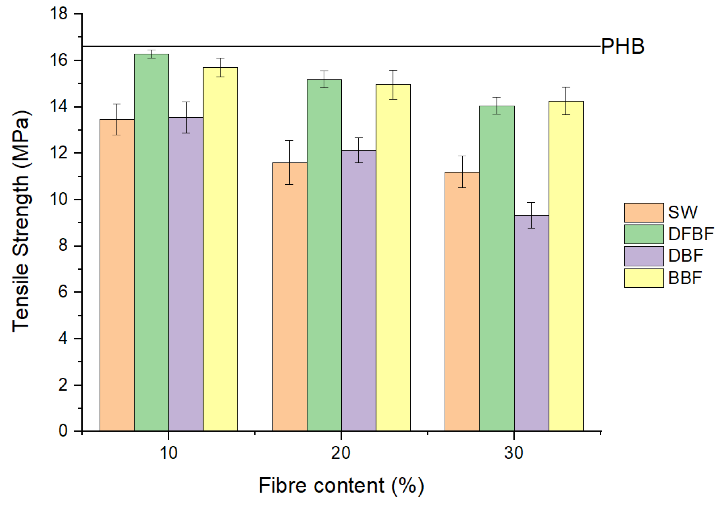
Any reinforcing effect was observed in the tensile strength of the composites, which is usually one of the main objectives of the preparation of composite materials. The addition of the fibres to the PHB matrix produced a detrimental effect, which was increased with the fibre content (
Figure 4). Nonetheless, DFBF and BBF fibres contributed to a loss in the tensile resistance of only 15% and 14%, respectively, with the 30% filled composites. A similar effect was also observed for the flexural strength of the composites. However, in that test, a reinforcement effect of the fibres was obtained with DFBF and BBF fibres. That difference in behaviour could be related to the combination of the tensile and compression stress during the flexural test. Moreover, the flexural strength decreased when the fibre content was over 20%. High contents of fibres could result in fibre agglomerates, and thus in poor dispersion of the fibres in the composite material. In addition, the behaviour of the strength property is generally linked to the interactions between the different phases of the composite material. A maximum of 21% increment regarding the PHB flexural strength was observed for the PHB-DFBF composite material filled with 20% DFBF fibres (material referenced as PHB-DFBF-20). The small increments observed in some cases and the loss of properties in the others indicate limited interaction between barley fibres and PHB matrix with the chemically untreated fibres. The case of bleached fibres (BBF) achieved similar values compared to DFBF ones, probably due to direct interaction between fibre and cellulose, the reinforcing component in natural fibres. SW reinforced composites results could be related to the low aspect ratio of these fibres, resulting in reinforcement more like particles than fibres, which have a lower reinforcing effect. Nonetheless, the results of the DBF reinforced composites were lower than expected. It could be related to the agglomeration of the fibres at the moment of compounding even if lignin removed during delignification process was expected to have a positive effect on the interaction with the PHB polymer matrix.
Although the composite materials were not improved in terms of tensile strength in comparison with neat PHB, the cost of these materials will be reduced, as the most expensive component is PHB. Moreover, as mentioned above, the strength reduction is really low for DFBF and BBF fibres. However, the negative effect of the fibre's presence could enlarge the durability of the materials in longtime applications as PHB degrades and biodegrades easily but not the fibres [
26,
27].
The behaviour of the elastic moduli, both in tensile and in bending, is in accordance with what was previsously observed with the strengths. The addition of fibres in the polymeric phase stiffed the composite material in a linear trend, except for the DFBF fibres. The best results were obtained for the DFBF fibres, except for the flexural modulus of the PHB-DFBF composite material filled with 30% DFBF fibres (material referenced as PHB-DFBF-30), indicating that better dispersion was obtained with these fibres up to a 20% fibre loading. Oppositely, this dispersion should have been improved at 30% fibre loading to allow the flexural modulus to continue to increase. A high dispersion was obtained with the SW fibres, which is probably related with the particle size of this reinforcement. DBF and BBF reinforced composites obtained lower moduli, due to the lower dispersion of such fibres and also to the presence of aggregates gener-ted at the moment of fibre drying.
Deformation is reduced in all the composite materials, due to the addition of a stiffed phase, and the same trend as that observed for the tensile and flexural strengths was obtained. The better interactions were obtained with the DFBF fibres and with the BBF ones. These interactions could be evidenced in the SEM pictures taken from the tensile tested samples (
Figure 5). SEM pictures of the SW and DBF-based composites showed clear voids between the fibres and the polymer matrix. Moreover, in the case of the DBF fibres, their diameter appears to be higher than 30 µm, illustrating the agglomeration phenomenon. This was the consequence of a poor dispersion as reported in the mechanical properties study [
28]. DFBF fibres showed a large diameter, also found in the MorFi analyser. Nonetheless, a better wettability of these fibres was found. Finally, BBF reinforced material showed broken fibres but also some voids at the fracture level, indicative of the slipping of the fibres during the test.
Impact resistance is a highly important property for applications for which a sudden impact is produced rather than a continuous applied stress. It is one of the most probably stresses occurred in agricultural pots, films, covers, etc. The addition of the fibres in the PHB matrix produced a clear reduction of the impact resistance in the notched and unnotched samples (
Table 3). This reduction is increased by the addition of more fibres in the composite material as the interphase volume,
i.e., the most fragile phase in the material consisting in the interactions between fibres and the polymer matrix, becomes more and more important.
The resistance of composite materials to impact is generally related to the energy absorbed by the matrix and the fibres (W
m and W
f, respectively), the energy required to initiate the fracture (W
i) and the energy absorbed by the interphase (W
fm) (Equation 1). The energy to initiate a fracture can be estimated from the difference between the impact resistance values of the unnotched and notched samples.
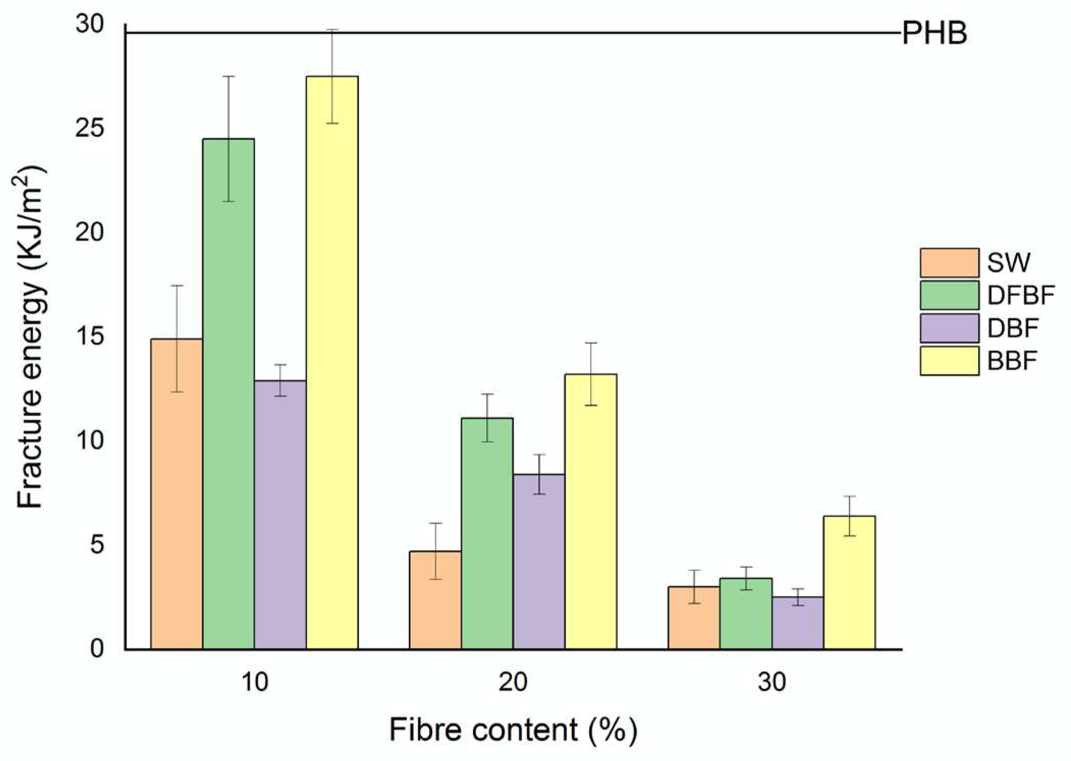
Figure 6 represents the fracture energies calculated for all the composite materials. Except for the formulations reinforced with 10% fibre content of DFBF and BBF fibres, all the composites showed a loss higher than 50% of the fracture energy of neat PHB, indicating that a fracture in the material will be easily produced. The PHB-BBF-10 composite material showed the better resistance to produce a fracture, while the PHB-DFBF-10 one showed quite similar energy. Nonetheless, the addition of higher fibre contents reduced drastically that energy. For PHB-DFBF composites, the results are related to the better wettability of the fibres, indicating a better interface as observed in the SEM pictures. On the other hand, the results obtained with the composites made of bleached fibres are not expected as, although the interactions are created between matrix and cellulose, the different polarities led to establish low energetic or fewer interactions. Nevertheless, the energy absorbed and dissipated by cellulose could be higher than the one by lignocellulosic fibres, where lignin covers the surface of the fibre and is not covalent bonded to cellulose chains, thus dissipating less energy.
3.3. Fibre Chosen for Process Intensification: Performance and Economical Evaluation
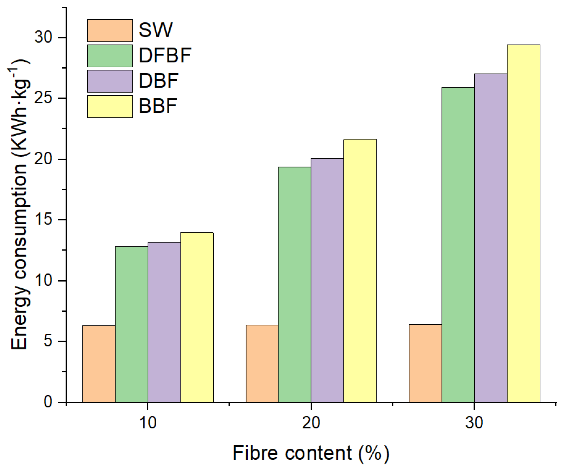
The study of the mechanical performance of the composite materials in a discontinuous process led to propose the use of defibrated (DFBF) and bleached (BBF) fibres as the reinforcing fibres for composite materials. These fibres have shown the better performances in the composite materials. However, the manufacture of these two fibres is totally different, and the production of bleached fibres includes two additional steps regarding the defibrated ones. These additional steps involve higher energy consumption and also generation of water waste. Thus, an analysis of the energy and reactants consumptions is interesting. PHB is, nowadays, an expensive polymer matrix. The addition of fibres could reduce the price, as the more expensive phase is reduced, but if the fibres are also expensive to produce, it will increase the price in an undesired form. The energy consumption of the composites prepared at the laboratory scale is shown in
Figure 7.
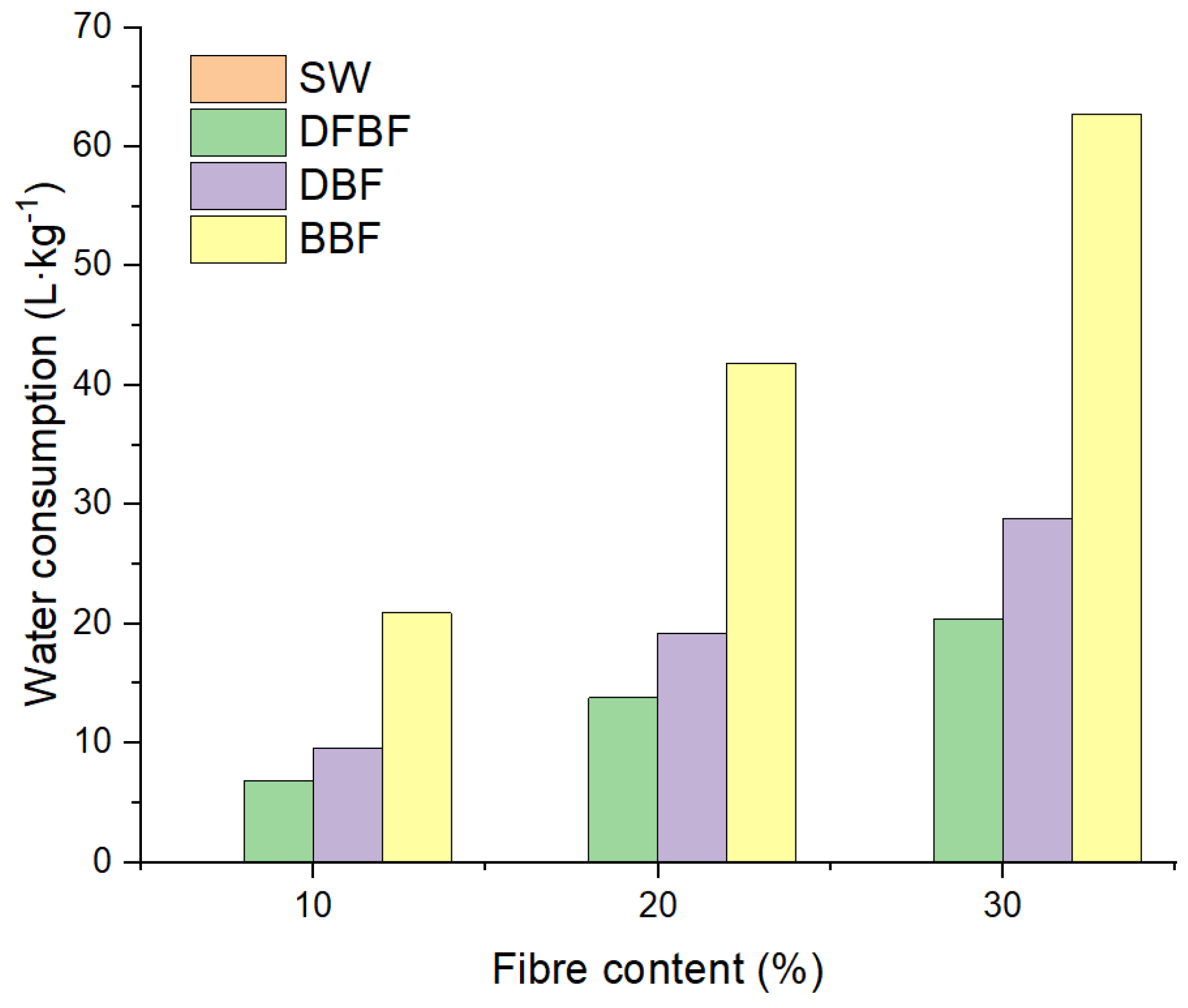
The energy consumption includes the milling, drying, compounding and transformation processes, and the additional steps for the fibre production. The most expensive part was the defibration process, as a significant increment of the energy consumption is observed for DFBF, and this energy consumption slightly increased for the DBF and BBF fibres. In terms of water consumption (
Figure 8), the use of the Gelimat mixer produced almost all the consumption for the SW-based composites. Nonetheless, this water could be used in a closed system and it was not considered in the calculation. Water consumption was increased again in the composite materials when the Sprout-Waldron equipment was used for the defibration process. Nonetheless, there is also an additional significant increment of water consumption for the BBF fibres, due to the cooking, bleaching and washing steps.
Besides, the price of the composites has a large dependency on the chemical reagents (NaOH and H
2O
2) and the price of PHB matrix. Spanish electrical energy cost (0.083 €/kW h in a mixture consumption in 2019) and the cost of water supplied in Girona (Spain) for industrial consumers (0,653 €/m
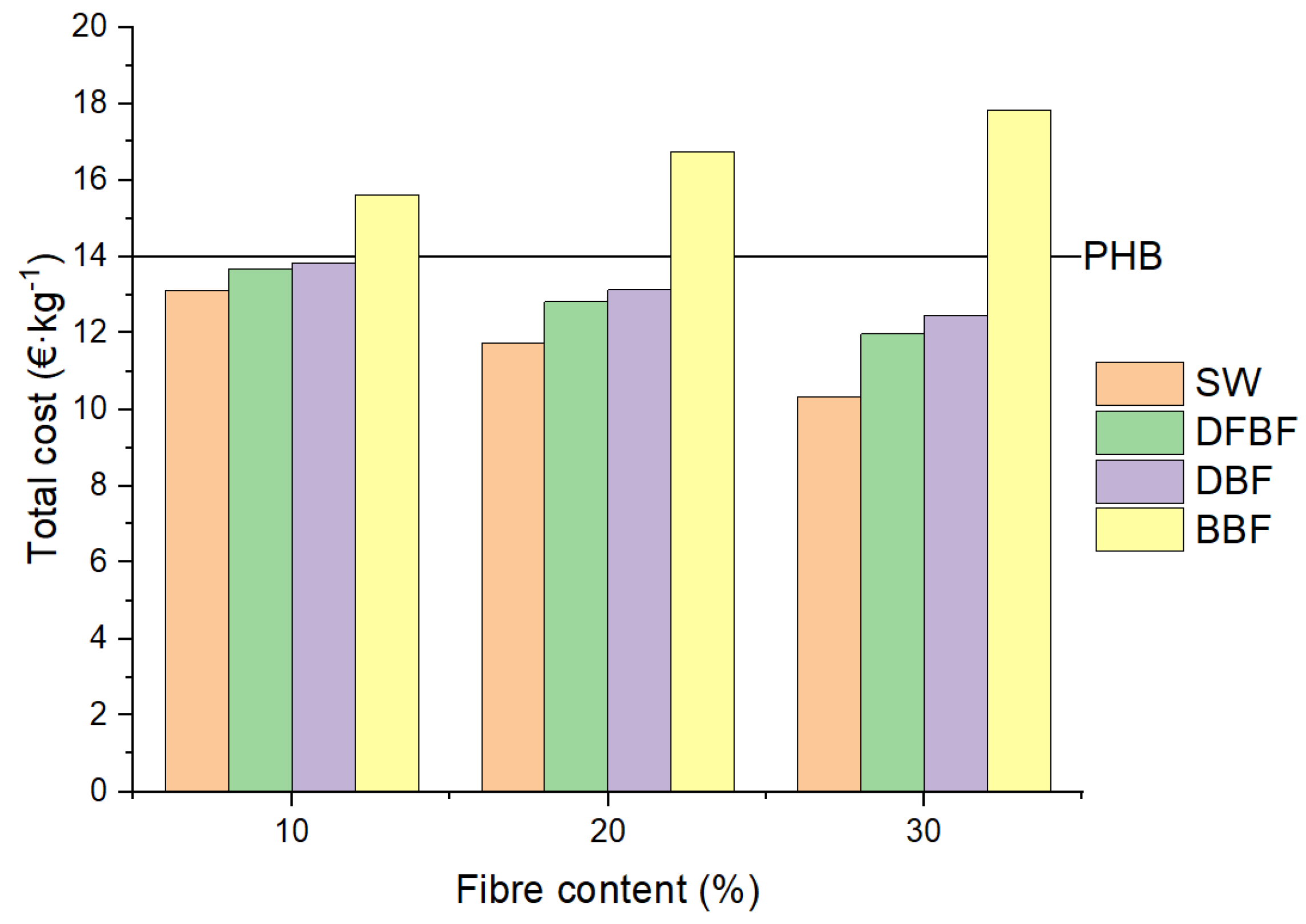
3) have been used for the calculation (
Figure 9). The use of reagents led to a significant increment of the cost of the composites, being higher than that of neat PHB for all the composites produced with these chemically treated fibres. On the other hand, the mechanical treatment of the fibres produced a reduction in the cost of the obtained composite materials, especially since the fibre content was raised in the material.
Although the reinforcement effect of BBF is superior to the other materials produced in this work, the cost for producing BBF-based composites is over the cost of neat PHB. The use of cheaper barley fibres while increasing the dimensional stability of the PHB-based composites over time seems to be a better choice. In that sense, the process intensification was conducted with the SW and DFBF-based composites.
3.4. Process Intensification of the Composite Compounding through Twin-Screw Extrusion
For process intensification, the composite compounding was conducted continuously in a twin-screw extruder. Raw materials used as reinforcement were sawdust (SW) and defibred fibres (DFBF), as above commented, and two filler contents were tested, i.e., 10% (w/w) and 30% (w/w), respectively. The extrusion process was also applied to neat PHB as control. Granules were then molded into test specimens to characterize PHB and the composite materials in terms of mechanical performance.
Thanks to the three mixing zones along modules 6 to 8, aggregates inside DFBF were well destroyed, and efficient dispersion of both types of reinforcing fibres was obtained inside PHB. This resulted in a stable compounding process, illustrated by stable motor torques throughout the productions (
Table 4). In addition, when adding more fibres, the increase in specific mechanical energy (SME) was quite slight (+15% max), meaning that fibres were well dispersed, even when larger quantities were added.
Injection of the test specimens was possible without any difficulty in automatic mode, even at the highest filler content. From a visual point of view, the injected specimens made from DFBF appeared slightly clearer and more homogeneous than those made from SW.
Table 5 and
Table 6 summarize the tensile and bending properties of the injected materials.
When comparing the tensile properties of neat PHB (
Table 3) and extruded PHB (
Table 5), a slight degradation of PHB has been observed due to the extrusion process. This was illustrated by a slight decrease in the tensile strength (from 16.6 MPa to 15.3 MPa) and especially by a significant reduction in elongation at break (from 13.3% to 5.3%). Adding SW and DFBF reduces PHB tensile strength, due to a lack of chemical affinity between the matrix and the filler. Besides, for composite materials made from the extruded granules, the tensile strength remained in the same order of magnitude as for the composites produced using the discontinuous process (
Table 3), even at 30% filler content, thus evidencing an effective dispersion of SW and DFBF fibres during extrusion compounding, which is however a short residence time process (around 2 min). The 10% and 30% filled DFBF-based extruded materials also revealed higher tensile strength than the SW-based ones. The same was observed with the Gelimat mixer, thus evidencing a more favorable morphology of the defibred fibres in comparison with the high size of SW particles.
The main differences between composites made with the discontinuous process and those originating from extrusion were observed for Young’s moduli and elongations at break. Even if PHB stiffening was still observed with extruded materials (
Table 5), the increase in the Young’s modulus in the presence of fibres was less significant compared with the Gelimat materials. In the same way, reduction in the PHB elongation at break was still effective inside the extruded materials. However, it was less significant than for the Gelimat ones. This suggests that the reinforcing fibres were probably reduced in length during the extrusion compounding process, although this could not be confirmed experimentally.
Flexural properties of the materials from the extruded granules are summarized in
Table 6. The addition of fibres to PHB resulted in more rigid materials. However, higher values of elongation at break were preserved for the extruded composites, even with a 30% (w/w) filler content, in comparison with the Gelimat ones. Lastly, when comparing flexural strengths at break of extruded materials each other, those of the DFBF-based ones were significantly higher. This confirms once again that the defibration process applied to sawdust to produce DFBF improved the fibre morphology, enabling better adhesion between PHB and DFBF.
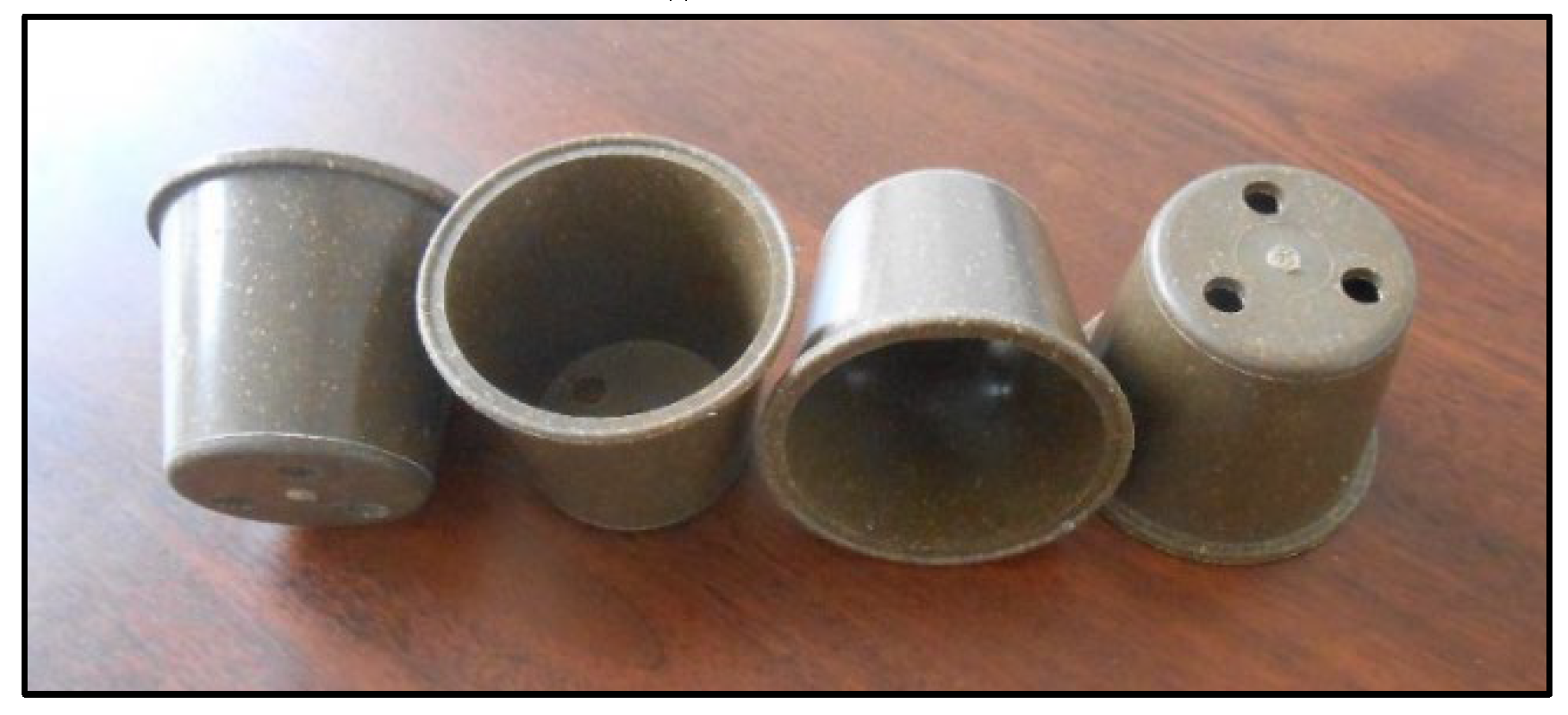
Granules made of 30% (w/w) SW or DFBF were used to mould flowerpots by injection (
Figure 10). Injection was still possible in automatic mode. Next paragraph will be dedicated to the simulation of the mechanical performance of these flowerpots.
3.6. Mechanical Assessment of Composite Materials: Flowerpots Simulation
The mechanical performance in a real product was tested using a flowerpot as reference. The digital mock-up is shown in
Figure 11. It was directly prepared from the injected pieces.
From an experimental point of view, the flowerpots were manufactured by injection moulding of the PHB-SW-30 and PHB-DFBF-30 granules obtained through continuous compounding using twin-screw extrusion.
For the mechanical performance test conducted on the flowerpot, the force applied in was 3 kg, and the subjections were fixed in the top of the flowerpot (
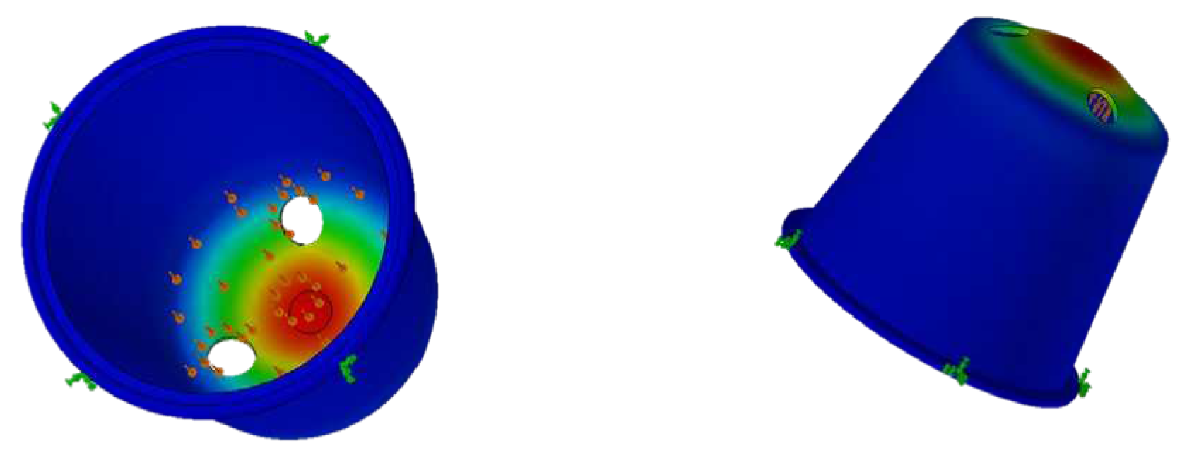
Figure 12). The analysis was carried out in the software, and the results obtained were the Von Misses stresses, the deformation of the product by regions and the safety factor.
Figure 13 shows an example of the reported data in terms of deformation.
Table 7 shows the results obtained for neat PHB, for all the composite materials analyzed (materials made of SW and DFBF fibres, added at 10-30% (w/w) fibre loading), and for the common plastics generally used for flowerpots,
i.e., high density polyethylene (HDPE) and polypropylene (PP).
The obtained results for all the composite materials were lower than the observed ones for the common plastics and neat PHB. Nonetheless, it was expected as HDPE, PP and PHB resistances were higher than those of the PHB-based composite materials, whatever the fibre studied and its incorporation rate. Besides, maximum deformations in composite materials were lower, due to the higher stiffness in these materials, which was the consequence of the PHB reinforcement with cellulosic fibres.
Finally, the safety factor indicates the suitability of the product to be used as a flowerpot in real conditions. A higher value than 1 is necessary for the material to be considered for such a use. All the PHB-based materials, including neat PHB, obtained values lower than 3 as observed for PP. Nevertheless, all of them showed values higher than 1. In the composite materials, the most appropriate ones were the DFBF-based composites.
One of the objectives is to incorporate contents of fibre as high as possible in a composite material, resulting in a reduction of the polymer volume. PHB is, nowadays, a quite expensive biobased polymer as its isolation process after biological synthesis by bacteria is still expensive. Including high contents of fibres reduces the cost of final product, although the price still remains expensive in comparison with common plastics. Thus, it is interesting to reduce the cost in the fibre preparation as much as possible. BBF are quite expensive fibres, considering both time and required reactants. Moreover, its yield is around 70% (w/w), which represents a significant loss of material. This is the reason why the DFBF fibres, which were only mechanically treated, were identified in the present study as the barley fibres to be privileged as a filler for PHB, being a good compromise between production cost and ability for PHB mechanical reinforcement.
4. Conclusions
A study of the production, properties, intensification production and mechanical assessment of composite materials made of PHB and barley fibres has been developed. Fibre treatment of barley reinforcement revealed a null reinforcement effect in terms of tensile strength, but some composites improved the flexural resistance (i.e., those based on DFBF and BBF fibres). The elastic modulus was increased for all the composites. Process intensification was performed with the DFBF fibres, i.e., the most easily scalable fibrous material that also showed one of the best performances in the composites. As for the discontinuous process, the samples did not show a reinforcement effect in mechanical terms, due to the poor affinity between PHB and fibres. The material with 30% DFBF was injected in automatic mode, showing the capacity to be easily produced in large scale. Finally, the mechanical assessment of flowerpots was studied by its simulation. The results showed the suitability of the materials produced to replace common petrol-based products.
Author Contributions
Conceptualization, J.A.M and P.E.; methodology, H.O.O. and C.R.; software, F.X.E.; validation, H.O.O., J.A.M; formal analysis, H.O.O. and C.R.; investigation, H.O.O., J.A.M., and P.E.; resources, J.A.M and P.E.; data curation, P.E. and F.X.E.; writing—original draft preparation, H.O.O. and P.E.; writing—review and editing, J.A.M and C.R.; visualization, C.R. and H.O.O.; supervision, F.X.E.; project administration, J.A.M. and P.E.; funding acquisition, J.A.M. and P.E. All authors have read and agreed to the published version of the manuscript.
Funding
This research was funded by Interreg program (POCTEFA 2014 - 2020), grant number Bioplast-EF 253/16.APC was funded by UdG. Dr. Oliver-Ortega aknowledges the funding of the research group TECTEX (2021 SGR 01056) from the Department de Recerca i Universitats de la Generalitat de Catalunya.
Institutional Review Board Statement
Not applicable.
Data Availability Statement
Data sharing not applicable.
Conflicts of Interest
The authors declare no conflict of interest. The funders had no role in the design of the study, in the collection, analyses, or interpretation of data, in the writing of the manuscript, or in the decision to publish the results.
References
- Association of Plastic Manufacturers (Organization) Plastics – the Facts 2020. PlasticEurope 2020, 16.
- González-Sánchez, C.; Martínez-Aguirre, A.; Pérez-García, B.; Martínez-Urreaga, J.; de la Orden, M.U.; Fonseca-Valero, C. Use of Residual Agricultural Plastics and Cellulose Fibers for Obtaining Sustainable Eco-Composites Prevents Waste Generation. J Clean Prod 2014, 83, 228–237. [Google Scholar] [CrossRef]
- Nisticò, R.; Evon, P.; Labonne, L.; Vaca-Medina, G.; Montoneri, E.; Vaca-Garcia, C.; Negre, M. Post-Harvest Tomato Plants and Urban Food Wastes for Manufacturing Plastic Films. J Clean Prod 2017, 167, 68–74. [Google Scholar] [CrossRef]
- Soil Degradable Bioplastics for a Sustainable Modern Agriculture; Malinconico, M. (Eds.) Green Chemistry and Sustainable Technology; Springer Berlin Heidelberg: Berlin, Heidelberg, 2017; ISBN 978-3-662-54128-9. [Google Scholar]
- Zhang, H.; Miles, C.; Ghimire, S.; Benedict, C.; Zasada, I.; DeVetter, L. Polyethylene and Biodegradable Plastic Mulches Improve Growth, Yield, and Weed Management in Floricane Red Raspberry. Sci Hortic 2019, 250, 371–379. [Google Scholar] [CrossRef]
- Torres-Tello, E. V.; Robledo-Ortíz, J.R.; González-García, Y.; Pérez-Fonseca, A.A.; Jasso-Gastinel, C.F.; Mendizábal, E. Effect of Agave Fiber Content in the Thermal and Mechanical Properties of Green Composites Based on Polyhydroxybutyrate or Poly(Hydroxybutyrate-Co-Hydroxyvalerate). Ind Crops Prod 2017, 99, 117–125. [Google Scholar] [CrossRef]
- Panaitescu, D.M.; Nicolae, C.A.; Frone, A.N.; Chiulan, I.; Stanescu, P.O.; Draghici, C.; Iorga, M.; Mihailescu, M. Plasticized Poly(3-Hydroxybutyrate) with Improved Melt Processing and Balanced Properties. J Appl Polym Sci 2017, 134. [Google Scholar] [CrossRef]
- Luo, S.; Netravali, A.N. Mechanical and Thermal Properties of Environment-Friendly “green” Composites Made from Pineapple Leaf Fibers and Poly(Hydroxybutyrate-Co-Valerate) Resin. Polym Compos 1999, 20, 367–378. [Google Scholar] [CrossRef]
- Carofiglio, V.E.; Stufano, P.; Cancelli, N.; De Benedictis, V.M.; Centrone, D.; Benedetto, E. De; Cataldo, A.; Sannino, A.; Demitri, C. Novel PHB/Olive Mill Wastewater Residue Composite Based Film: Thermal, Mechanical and Degradation Properties. J Environ Chem Eng 2017, 5, 6001–6007. [Google Scholar] [CrossRef]
- Singh, S.; Mohanty, A.K.; Sugie, T.; Takai, Y.; Hamada, H. Renewable Resource Based Biocomposites from Natural Fiber and Polyhydroxybutyrate-Co-Valerate (PHBV) Bioplastic. Compos Part A Appl Sci Manuf 2008, 39, 875–886. [Google Scholar] [CrossRef]
- Coats, E.R.; Loge, F.J.; Wolcott, M.P.; Englund, K.; McDonald, A.G. Production of Natural Fiber Reinforced Thermoplastic Composites through the Use of Polyhydroxybutyrate-Rich Biomass. Bioresour Technol 2008, 99, 2680–2686. [Google Scholar] [CrossRef]
- Tănase, E.E.; Popa, M.E.; Râpă, M.; Popa, O. PHB/Cellulose Fibers Based Materials: Physical, Mechanical and Barrier Properties. Agriculture and Agricultural Science Procedia 2015, 6, 608–615. [Google Scholar] [CrossRef]
- Melo, J.D.D.; Carvalho, L.F.M.; Medeiros, A.M.; Souto, C.R.O.; Paskocimas, C.A. A Biodegradable Composite Material Based on Polyhydroxybutyrate (PHB) and Carnauba Fibers. Compos B Eng 2012, 43, 2827–2835. [Google Scholar] [CrossRef]
- Gourier, C.; Bourmaud, A.; Le Duigou, A.; Baley, C. Influence of PA11 and PP Thermoplastic Polymers on Recycling Stability of Unidirectional Flax Fibre Reinforced Biocomposites. Polym Degrad Stab 2017, 136, 1–9. [Google Scholar] [CrossRef]
- Sánchez-Safont, E.L.; Aldureid, A.; Lagarón, J.M.; Cabedo, L.; Gámez-Pérez, J. Study of the Compatibilization Effect of Different Reactive Agents in PHB/Natural Fiber-Based Composites. Polymers 2020, 12, 1967. [Google Scholar] [CrossRef] [PubMed]
- Granda, L.A.; Espinach, F.X.; Tarrés, Q.; Méndez, J.A.; Delgado-Aguilar, M.; Mutjé, P. Towards a Good Interphase between Bleached Kraft Softwood Fibers and Poly(Lactic) Acid. Compos B Eng 2016, 99, 514–520. [Google Scholar] [CrossRef]
- Ardanuy, M.; Antunes, M.; Velasco, J.I. Vegetable Fibres from Agricultural Residues as Thermo-Mechanical Reinforcement in Recycled Polypropylene-Based Green Foams. Waste Management 2012, 32, 256–263. [Google Scholar] [CrossRef] [PubMed]
- BIOPLAST (EFA253/16). Available online: https://www.bioplast-poctefa.eu/.
- Smith, M.K.M.; Paleri, D.M.; Abdelwahab, M.; Mielewski, D.F.; Misra, M.; Mohanty, A.K. Sustainable Composites from Poly(3-Hydroxybutyrate) (PHB) Bioplastic and Agave Natural Fibre. Green Chemistry 2020, 22, 3906–3916. [Google Scholar] [CrossRef]
- Oliver-Ortega, H.; Granda, L.A.; Espinach, F.X.; Méndez, J.A.; Julian, F.; Mutjé, P. Tensile Properties and Micromechanical Analysis of Stone Groundwood from Softwood Reinforced Bio-Based Polyamide11 Composites. Compos Sci Technol 2016, 132, 123–130. [Google Scholar] [CrossRef]
- Espinosa, E.; Tarrés, Q.; Delgado-Aguilar, M.; González, I.; Mutjé, P.; Rodríguez, A. Suitability of Wheat Straw Semichemical Pulp for the Fabrication of Lignocellulosic Nanofibres and Their Application to Papermaking Slurries. Cellulose 2015, 837–852. [Google Scholar] [CrossRef]
- Domínguez-Robles, J.; Tarrés, Q.; Delgado-Aguilar, M.; Rodríguez, A.; Espinach, F.X.; Mutjé, P. Approaching a New Generation of Fiberboards Taking Advantage of Self Lignin as Green Adhesive. Int J Biol Macromol 2018, 108, 927–935. [Google Scholar] [CrossRef]
- Ovalle-Serrano, S.A.; Blanco-Tirado, C.; Combariza, M.Y. Exploring the Composition of Raw and Delignified Colombian Fique Fibers, Tow and Pulp. Cellulose 2018, 25, 151–165. [Google Scholar] [CrossRef]
- Serrano, C.; Monedero, E.; Lapuerta, M.; Portero, H. Effect of Moisture Content, Particle Size and Pine Addition on Quality Parameters of Barley Straw Pellets. Fuel Processing Technology 2011, 92, 699–706. [Google Scholar] [CrossRef]
- Salmén, L.; Stevanic, J.S. Effect of Drying Conditions on Cellulose Microfibril Aggregation and “Hornification. Cellulose 2018, 25, 6333–6344. [Google Scholar] [CrossRef]
- Sánchez-Safont, E.L.; Aldureid, A.; Lagarón, J.M.; Gamez-Perez, J.; Cabedo, L. Effect of the Purification Treatment on the Valorization of Natural Cellulosic Residues as Fillers in PHB-Based Composites for Short Shelf Life Applications. Waste Biomass Valorization 2021, 12, 2541–2556. [Google Scholar] [CrossRef]
- Oliver-Ortega, H.; Julián, F.; Espinach, F.X.; Méndez, J.A. Simulated Environmental Conditioning of PHB Composites Reinforced with Barley Fibres to Determine the Viability of Their Use as Plastics for the Agriculture Sector. Polymers 2023, 15. [Google Scholar] [CrossRef]
- da Silva Moura, A.; Demori, R.; Leão, R.M.; Crescente Frankenberg, C.L.; Campomanes Santana, R.M. The Influence of the Coconut Fiber Treated as Reinforcement in PHB (Polyhydroxybutyrate). Composites Mater Today Commun 2019, 18, 191–198. [Google Scholar] [CrossRef]
Figure 1.
Comparison of the production of different cereals in the EU (Source: Eurostat).
Figure 1.
Comparison of the production of different cereals in the EU (Source: Eurostat).
Figure 2.
Fibre production process.
Figure 2.
Fibre production process.
Figure 3.
Optical microscope photographs of the reinforcing fibres (×20 magnification).
Figure 3.
Optical microscope photographs of the reinforcing fibres (×20 magnification).
Figure 4.
Comparison of the tensile strength of PHB-based composites regarding the fibre used and its content.
Figure 4.
Comparison of the tensile strength of PHB-based composites regarding the fibre used and its content.
Figure 5.
SEM microphotographies at 30 µm of the 30% filled composite materials.
Figure 5.
SEM microphotographies at 30 µm of the 30% filled composite materials.
Figure 6.
Fracture energy for the PHB-based composite materials.
Figure 6.
Fracture energy for the PHB-based composite materials.
Figure 7.
Energy consumption per kg of composite material produced.
Figure 7.
Energy consumption per kg of composite material produced.
Figure 8.
Water consumption per kg of composite material produced.
Figure 8.
Water consumption per kg of composite material produced.
Figure 9.
Total production cost per kg of composite material produced.
Figure 9.
Total production cost per kg of composite material produced.
Figure 10.
Example of flowerpot injected from the PHB-DFBF-30 composite material.
Figure 10.
Example of flowerpot injected from the PHB-DFBF-30 composite material.
Figure 11.
Digital mock-up of the flowerpot used for simulation.
Figure 11.
Digital mock-up of the flowerpot used for simulation.
Figure 12.
Grid and force direction applied in the mock-up of the flowerpot.
Figure 12.
Grid and force direction applied in the mock-up of the flowerpot.
Figure 13.
Reported results from the simulation in terms of deformation.
Figure 13.
Reported results from the simulation in terms of deformation.
Table 1.
Chemical composition of reinforcing fibres in % of dry matter. Error is described between brackets.
Table 1.
Chemical composition of reinforcing fibres in % of dry matter. Error is described between brackets.
| |
SW/DFBF fibres |
DBF fibres |
BBF fibres |
| Ashes (%) |
6.8 (0.4) |
2.7 (0.1) |
2.1 (0.7) |
| Extractives (%) |
2.3 (0.3) |
1.7 (0.3) |
1.4 (0.2) |
| Lignin (%) |
19.6 (0.2) |
15.1 (2.2) |
10.5 (3.5) |
| Holocellulose (%) |
71.3 |
80.5 |
86.0 |
Table 2.
Morphological data of fibres.
Table 2.
Morphological data of fibres.
| Fibre |
Mean Weighted Length (µm) |
Diameter (µm) |
Fines (%) |
| DFBF |
291.6 (24.8) |
30.5 (1.2) |
82.7 (1.4) |
| DBF |
290.0 (32.6) |
21.8 (0.4) |
90.9 (7.5) |
| BBF |
279.5 (0.7) |
21.7 (0.3) |
74.6 (14.4) |
Table 3.
Mechanical properties of PHB and PHB-based composites (standard deviations are shown between brackets).
Table 3.
Mechanical properties of PHB and PHB-based composites (standard deviations are shown between brackets).
| Sample |
Fibre content (%) |
Tensile properties |
Flexural properties |
Impact resistance |
| |
|
σt (MPa) |
Et (GPa) |
εt (%) |
σf (MPa) |
Ef (GPa) |
εf (%) |
Iu (kJ/m2) |
In (kJ/m2) |
| PHB |
0 |
16.6 (0.2) |
0.80 (0.01) |
13.3 (1.1) |
23.1 (1.1) |
0.31 (0.20) |
8.3 (0.2) |
41.6 (1.9) |
12.0 (1.6) |
| PHB-SW |
10 |
13.5 (0.7) |
1.10 (0.05) |
3.7 (0.3) |
22.3 (2.8) |
1.25 (0.11) |
4.4 (0.7) |
18.8 (3.8) |
3.9 (1.3) |
| 20 |
11.6 (0.9) |
1.54 (0.05) |
1.6 (0.5) |
22.8 (2.1) |
1.78 (0.09) |
3.0 (1) |
8.2 (2.3) |
3.5 (0.4) |
| 30 |
11.2 (0.7) |
1.85 (0.05) |
1.1 (0.1) |
22.1 (0.6) |
2.62 (0.09) |
1.5 (0) |
6.8 (1.3) |
3.8 (0.3) |
| PHB-DFBF |
10 |
16.3 (0.2) |
1.12 (0.04) |
5.1 (0.1) |
27.2 (0.3) |
1.45 (0.07) |
6.0 (0.3) |
29.7 (5.7) |
5.2 (0.3) |
| 20 |
15.2 (0.3) |
1.61 (0.03) |
2.8 (0.1) |
27.9 (0.5) |
2.10 (0.06) |
3.8 (0.4) |
15.7 (1.9) |
4.6 (0.4) |
| 30 |
14.1 (0.4) |
2.17 (0.13) |
1.3 (0.1) |
22.6 (0.2) |
1.41 (0.07) |
1.5 (0.1) |
6.1 (0.8) |
2.7 (0.3) |
| PHB-DBF |
10 |
13.6 (0.7) |
1.38 (0.05) |
2.2 (0.3) |
23.2 (0.4) |
1.50 (0.03) |
3.0 (0.2) |
16.4 (1.1) |
3.5 (0.4) |
| 20 |
12.1 (0.5) |
1.64 (0.03) |
1.3 (0.1) |
20.6 (0.8) |
1.93 (0.05) |
1.6 (0.1) |
12.1 (1.8) |
3.7 (0.1) |
| 30 |
9.3 (0.6) |
1.80 (0.08) |
0.7 (0.1) |
19.2 (1.6) |
2.24 (0.07) |
1.1 (0.2) |
5.1 (0.3) |
2.6 (0.5) |
| PHB-BBF |
10 |
15.7
(0.4) |
1.11 (0.02) |
5.4 (0.3) |
25.4 (0.8) |
1.27 (0.08) |
7.0 (0.3) |
33.9 (4.2) |
6.4 (0.3) |
| 20 |
15.0 (0.6) |
1.51 (0.05) |
2.8 (0.3) |
27.0 (0.8) |
1.78 (0.04) |
4.3 (0.1) |
18.1 (2.9) |
4.9 (0.1) |
| 30 |
14.3 (0.6) |
1.85 (0.07) |
1.8 (0.1) |
24.6 (0.8) |
2.03 (0.05) |
2.8 (0.2) |
10.9 (1.7) |
4.5 (0.2) |
Table 4.
Engine torque and specific mechanical energy (SME) during twin-screw extrusion.
Table 4.
Engine torque and specific mechanical energy (SME) during twin-screw extrusion.
| Sample |
Filler type |
Filler content
(%, w/w) |
Motor torque
(%) |
SME
(W h/kg) |
| PHB |
- |
0 |
32.4 (0.9) |
191 (5) |
| PHB-SW-10 |
SW |
10 |
31.7 (0.9) |
190 (5) |
| PHB-SW-30 |
SW |
30 |
37.0 (0.3) |
219 (2) |
| PHB-DFBF-10 |
DFBF |
10 |
33.2 (0.6) |
194 (4) |
| PHB-DFBF-30 |
DFBF |
30 |
33.3 (0.8) |
197 (5) |
Table 5.
Tensile properties of the composite materials made from the extruded granules.
Table 5.
Tensile properties of the composite materials made from the extruded granules.
| Sample |
Filler type |
Filler content
(%, w/w) |
σt
(MPa) |
Et
(GPa) |
εt
(%) |
| PHB |
- |
0 |
15.3 (0.5) |
0.80 (0.03) |
5.3 (0.4) |
| PHB-SW-10 |
SW |
10 |
14.9 (0.3) |
0.97 (0.01) |
5.0 (0.4) |
| PHB-SW-30 |
SW |
30 |
12.2 (0.3) |
1.06 (0.06) |
2.5 (0.3) |
| PHB-DFBF-10 |
DFBF |
10 |
16.8 (0.8) |
0.87 (0.05) |
3.8 (0.4) |
| PHB-DFBF-30 |
DFBF |
30 |
13.7 (0.4) |
0.99 (0.06) |
2.5 (0.1) |
Table 6.
Bending properties of the composite materials made from the extruded granules.
Table 6.
Bending properties of the composite materials made from the extruded granules.
| Sample |
Filler type |
Filler content
(%, w/w) |
σf
(MPa) |
Ef
(MPa) |
εf
(%) |
| PHB |
- |
0 |
31.1 (0.4) |
0.88 (0.06) |
10.2 (0.4) |
| PHB-SW-10 |
SW |
10 |
24.7 (1.7) |
1.14 (0.10) |
5.8 (0.6) |
| PHB-SW-30 |
SW |
30 |
25.6 (0.7) |
1.64 (0.09) |
2.8 (0.3) |
| PHB-DFBF-10 |
DFBF |
10 |
28.4 (1.9) |
1.37 (0.08) |
3.9 (0.5) |
| PHB-DFBF-30 |
DFBF |
30 |
28.0 (1.1) |
1.89 (0.06) |
2.5 (0.1) |
Table 7.
Mechanical assessment of the composite materials versus neat PHB and common plastics.
Table 7.
Mechanical assessment of the composite materials versus neat PHB and common plastics.
| |
HDPE |
PP |
PHB |
SW-based composites |
DFBF-based composites |
| Fibre Content (%) |
0 |
0 |
0 |
10 |
20 |
30 |
10 |
20 |
30 |
| Maximum Von Misses resistance before break (MPa) |
22.1 |
24.5 |
16.6 |
13.5 |
11.6 |
11.2 |
16.3 |
15.2 |
14.1 |
| Maximum Von Misses resistance in flowerpot (MPa) |
7.8 |
7.8 |
7.7 |
7.7 |
7.7 |
7.7 |
7.7 |
7.7 |
7.7 |
| Deformation (mm) |
2.0 |
1.3 |
2.3 |
1.7 |
1.3 |
0.9 |
1.5 |
1.0 |
0.8 |
| Safety Factor |
2.8 |
3.2 |
2.1 |
1.7 |
1.5 |
1.4 |
2.1 |
2.0 |
1.8 |
|
Disclaimer/Publisher’s Note: The statements, opinions and data contained in all publications are solely those of the individual author(s) and contributor(s) and not of MDPI and/or the editor(s). MDPI and/or the editor(s) disclaim responsibility for any injury to people or property resulting from any ideas, methods, instructions or products referred to in the content. |
© 2023 by the authors. Licensee MDPI, Basel, Switzerland. This article is an open access article distributed under the terms and conditions of the Creative Commons Attribution (CC BY) license (http://creativecommons.org/licenses/by/4.0/).
