1. Introduction
In various branches of technology (construction, mechanical engineering, aircraft building, and shipbuilding), orthotropic plates are widely used, in which the physical and mechanical characteristics of materials are symmetrical about three mutually perpendicular planes (wood, plywood, reinforced concrete). Many designs also have orthotropic properties, for example, corrugated and ribbed plates. A lot of work is devoted to the study of orthotropic plates. Recent works include [
1,
2,
3].
A study [
4] showed that the general anisotropic property and the variable in-plane stiffness property inherent in composites create significant challenges in the static and dynamic analysis of these new types of variable stiffness composite structures. Therefore, it is important to develop mechanical models and calculation methods for composite lamellar-shell structures of variable stiffness to understand their complex mechanical mechanisms and promote their further application in aerospace engineering.
Publications devoted to triangular orthotropic plates appear much less frequently. In one of the first such publications [
5], large amplitude oscillations of right triangular anisotropic plates were analyzed based on von Kármán governing equations. Utilizing the Bubnov-Galerkin procedure, a nonlinear second-order differential equation for the unknown time function was drawn. The equation was solved in terms of Jacobian elliptic functions.
Vibration analysis and multi-objective optimization of stiffened triangular plate was done in [
6]. The triangular plate included stiffeners (ribs), which were parallel to each other and parallel to one edge of the triangle. The governing equation of transversal deflection of the plate was obtained by considering the effects of orthotropic characteristics and external excitation. The ordinary differential equation for the system's time response was obtained using the Bubnov-Galerkin method. In the next step, a multi-objective optimization was carried out considering two conflicting objective functions, i.e., maximizing the system's nonlinearity and minimizing the amplitude of vibration. Four decision variables were considered, including the plate's thickness, geometry, and the distance of the stiffeners. Finally, the effects of different parameters on the optimal solutions and the distribution of decision variables were investigated.
Buckling analysis of general triangular anisotropic plates in [
7] and [
8] with different boundary conditions subjected to combined in-plane loads was considered. Solutions for plate buckling were obtained using the Rayleigh-Ritz method combined with a variational formulation. The numerical results were obtained for various triangular geometries with isotropic and anisotropic material properties. The effect of transverse-shear deformation was studied for different triangular geometries. The results confirm the importance of including the effect of transverse-shear deformation in the buckling analysis of composite plates. These results were later used in [
9] and [
10] for optimal design of composite grid-stiffened aircraft panels subjected to global and local buckling constraints. The local buckling of aircraft skin segments is assessed with material anisotropy and transverse shear flexibility. The local buckling of stiffener segments was also assessed.
An accurate and simplified solution was provided in [
11] for the free vibration problem of simply supported thin general triangular plates. The proposed method applies to thin plates with linear boundaries regardless of their geometrical shapes. Results were compared with previously published data for the isosceles and general triangles. Good agreements were reported. Although the paper deals only with simple support conditions, the article claims that any combination of classical boundary conditions can be handled with or without complicating factors.
The p-Ritz method operates with mathematically complete two-dimensional polynomial functions, and boundary polynomial equations raised to appropriate powers are used to approximate the displacements. In the [
12], the p-Ritz method was used to derive the governing eigenvalue equation for the buckling behavior of triangular plates with both translational and rotational elastic edge constraints. The influence of elastic edge supports on the buckling factors for triangular plates of various vertex angles (aspect ratios) and boundary conditions was examined. The buckling solutions for isosceles and right-angled triangular plates with elastic edge constraints were presented.
The unilateral buckling behavior of point-restrained triangular plates was studied [
13]. The Rayleigh-Ritz method with polynomial-based shape functions was used to investigate the unilateral buckling behavior of triangular plates with various loading combinations, aspect ratios, boundary conditions, and point restraint configurations. Polynomials and tensionless foundations modeled the displacement functions and restraining medium, respectively. The results are obtained for different boundary conditions, aspect ratios, and various in-plane compressive and shear loadings. Convergence and comparison studies were undertaken to confirm the validity and precision of the solution method.
Free and forced multi-frequency vibrations of stiffened triangular plates with the stiffeners were investigated [
14]. The governing motion equation for a triangular plate was developed based on the von Kármán theory. The nonlinear ordinary differential equation of the system using the Bubnov-Galerkin approach was obtained. Closed-form expressions for the free undamped and large-amplitude vibration of an orthotropic triangular elastic plate were presented using two analytical methods, namely, the energy balance method [
15] and the variational approach. It is demonstrated that those two methods are straightforward and reliable techniques for solving those nonlinear differential equations.
A nonlinear vibration of a triangular shape plate with several stiffeners was studied [
16]. The Bubnov-Galerkin method obtained the ordinary differential equation for the system's time response. A genetic-based multi-objective optimization was performed to find the geometry and locations of the plate's stiffeners.
Three-dimensional structures in the form of triangular plates of thin and medium thickness with homogeneous and inhomogeneous characteristics of materials (isotropic and orthotropic) were considered [
17]. The finite difference method was applied using a grid of scalene triangles as a resolving method. Based on a numerical algorithm and the author's Fortran programs, the leading parameters were obtained from transverse and in-plane loads under various boundary conditions (in bending, buckling, and free oscillations).
In [
18], free vibration characteristics of moderately thick composite materials triangular plates under multi-point support boundary conditions were analyzed. An improved Fourier series method was used. Energy equations are established based on the first-order shear deformation theory. The Rayleigh-Ritz technique is adopted to solve unknown coefficients of energy equations with the multi-point support boundary conditions. This study aimed to simulate real engineering structures with multi-point support. It was shown that the method has higher accuracy than the finite element method.
In-plane vibration of arbitrary laminated triangular plates with elastic boundary conditions was studied [
19] by the Chebyshev-Ritz method. The coordinate transformation mapped the arbitrarily shaped triangular laminated plate into a square plate to facilitate energy calculation. The displacement functions of the square plate after transformation were expressed as two-dimensional Chebyshev polynomials multiplied by coefficients. The arbitrary elastic boundary conditions of the plate were obtained by changing the stiffness values of each spring with artificial virtual spring technology. The in-plane free vibration characteristics of the triangular laminated plate under different boundary conditions were calculated. The accuracy of this method was verified by comparing finite element results with experimental results. The comparison shows that the present method has good convergence and satisfactory actuarial accuracy.
The bending of cantilever triangular plates at the same inclination angles of the side edges to the base was investigated [
20]. A finite difference method was applied. Combining the results was applied to solve the problem of an acute angle at the top of the plate. The results of calculating a cantilever bar of variable bending stiffness were combined with similar results of calculating a triangular plate supported along the contour using a reduction factor. This study's theoretical provisions and applied results could be partially used to investigate the bending of orthotropic scalene triangle plates supported along the edges.
The frequency and mode of free vibrations of thin isotropic triangular plates with a central hole for different boundary conditions were investigated [
21]. The finite-element method was used. Some plates' topology of vibration modes was compared to square plates with hinged and clamped edges. The numerical values of the natural frequencies and modes of triangular plates are in good agreement with the experimental results.
The simplistic superposition method was used for analytic free vibration solutions of right triangular plates [
22]. The problem was solved by dividing it into three subproblems that were solved by the symplectic techniques via imposing the variable separation on the Hamiltonian-system-based governing equation and symplectic eigen expansion. Then, the analytic frequency and mode shape solutions were obtained by requiring the equivalence between the original problem and the superposition. The comparison with the numerical results for the right triangular plates confirmed the approach's convergence and accuracy. For modeling channel flows, approaches based on the numerical solution of two-dimensional Saint-Venant equations have shown high efficiency and sufficient accuracy. The derivation of these equations, numerical integration algorithms, and examples of calculations are given, for example, in [
5,
6,
7,
8]. However, the Saint-Venant model is open-ended for deformable channels and requires addition, for instance, with an equation or system of equations to find variables in the time and space of bottom marks.
This paper aimed to develop and adapt the complex triangular mesh for the finite difference method. The main application is to receive the stress-strain state of orthotropic scalene triangle plates, as it wasn't researched enough. The objective is to analyze the stress-strain state of orthotropic triangle plates under different loads and boundary conditions. The other objective is the parametric analysis of orthotropic coefficients in boundary conditions and the influence of base angles on strength parameters and load-bearing capacity.
2. Methods
The object of study is a transversely bent triangular plate made of orthotropic material fixed along the edges of the plate under the action of a uniformly distributed load.
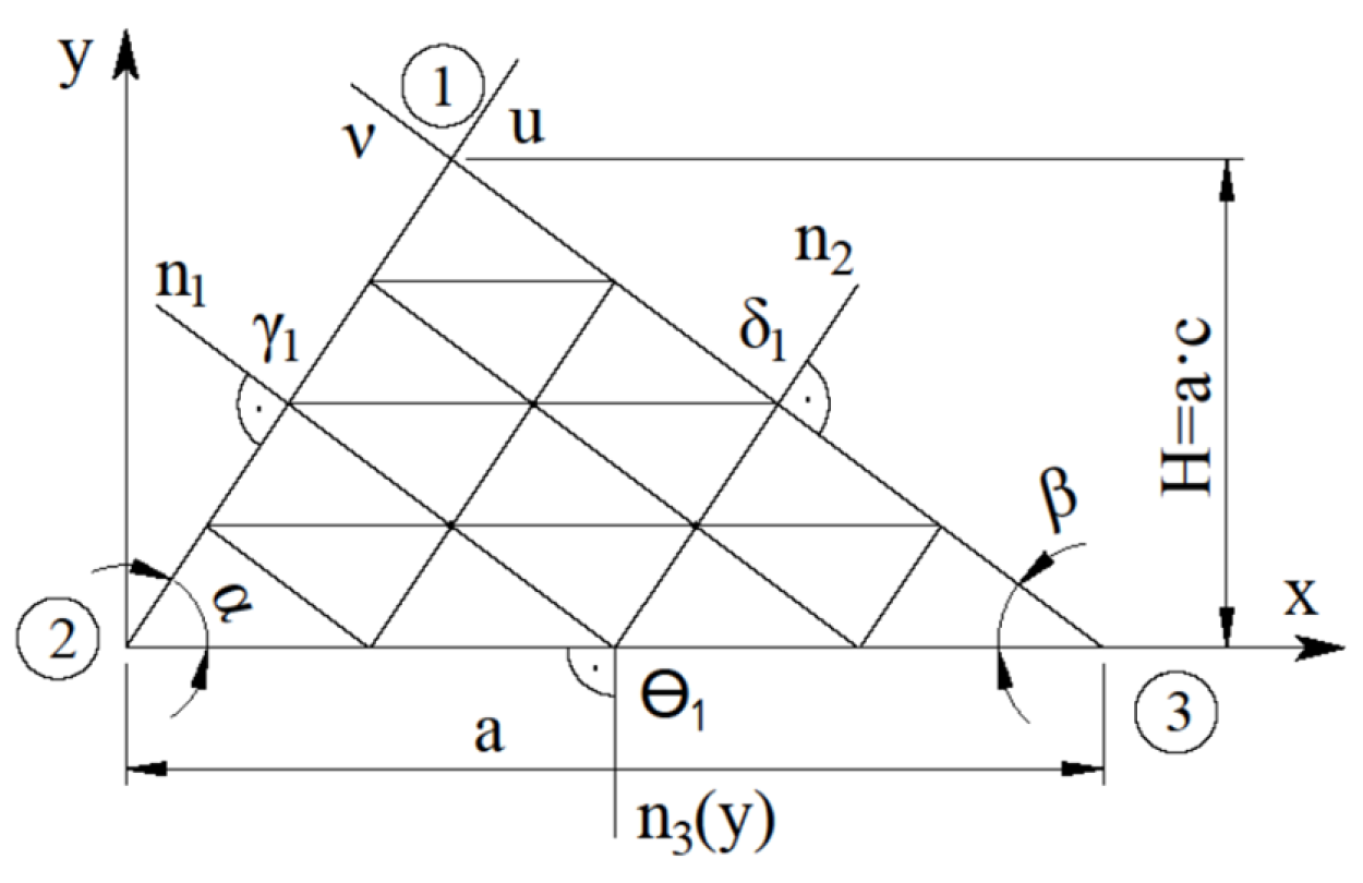
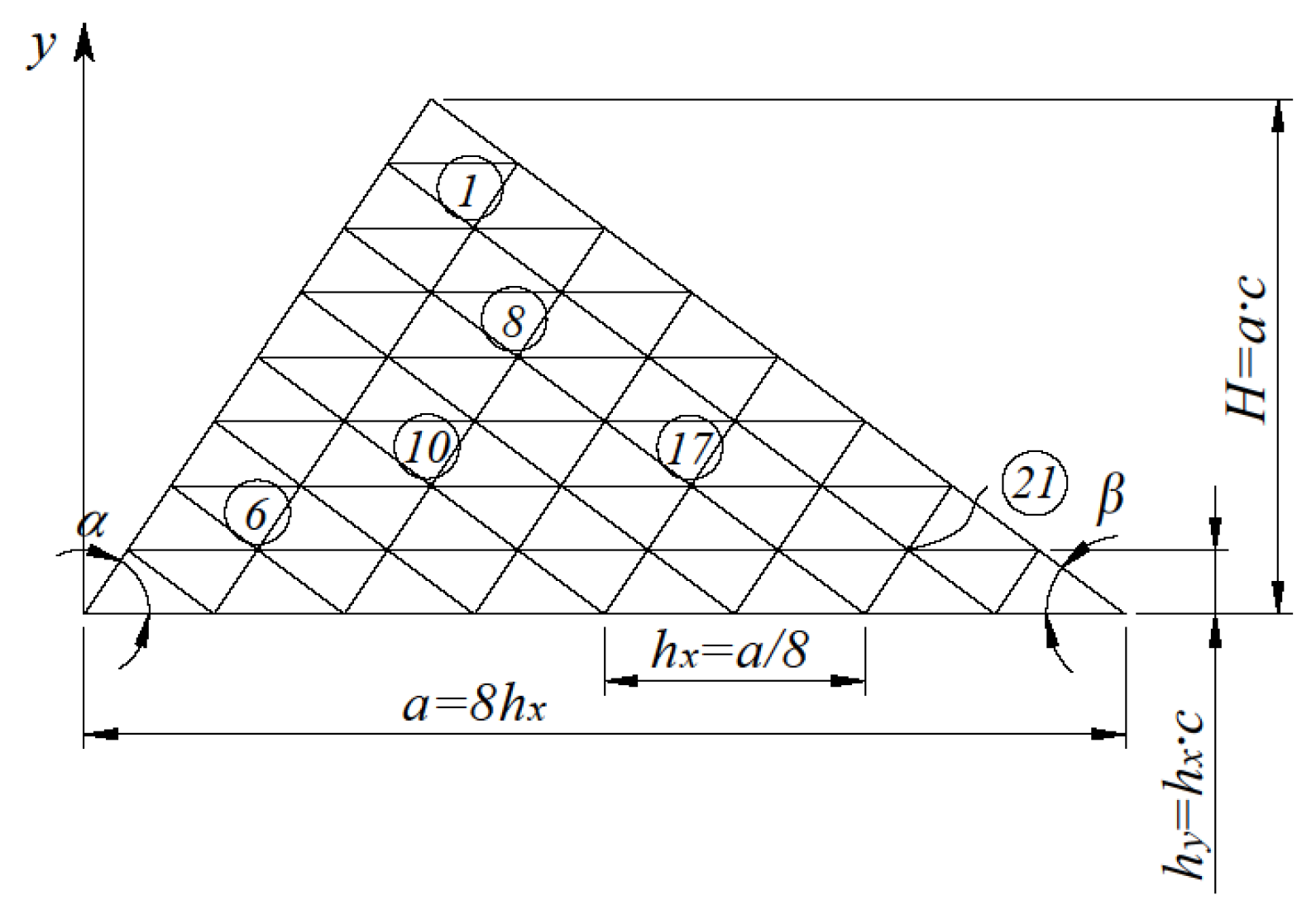
Figure 1 shows the calculation scheme for the triangular plate.
The configuration of the plate is determined by three parameters: a this is the base of the triangle (plate); α, β are the angles of inclination of the side edges to the base (in the general case, α is not equal to β).
The study used the well-known initial differential equation to bend orthotropic plates [
24,
25,
26]. The equation has the form:
where
w=w(x,y) is the deflection function,
q is the intensity of the stationary transverse distributed load in the plane of the plate,
are bending and torsional stiffness of the orthotropic material,
x, y are Cartesian coordinates.
The flexural and torsional stiffness of an orthotropic material is determined as follows:
Here:
, are the elastic modulus of the material in two mutually perpendicular planes;
, are Poisson's ratios in two mutually perpendicular planes;
G is the shear modulus;
is the torsional bending stiffness;
t is the thickness of the plate.
Next, the orthotropy coefficients are introduced:
Equation (1), taking into account the accepted notations (2) and (3), has the form:
Bending moments and torque, taking into account the orthotropy of the structural material, have the form:
The boundary conditions of plates supported along their edges are written in the same way as for bending isotropic plates (with hinged or rigidly fixed edges of the plate):
where
j is edge numbers,
is the directions of the normal to the corresponding edges of the plate,
is bending moment in the normal direction
Table 1.
Fractional composition of sand in the model.
Table 1.
Fractional composition of sand in the model.
| Fraction diameter (mm) |
1-0.5 |
0.5-0.25 |
0.25-0.1 |
<0.1 |
| Content (%) |
0.2 |
31.9 |
67.7 |
0.2 |
The cross-sectional shape of the model closely resembled half the cross-section of a trape.
3. Results
It is known that the finite difference method can be a preferable choice for problems on a uniform grid. The finite difference method with a mesh of scalene triangles was used to apply equation (4) to the bending calculation of a triangular orthotropic plate (
Figure 1). The grid of scalene triangles fits well into the oblique contour of the triangular plates.
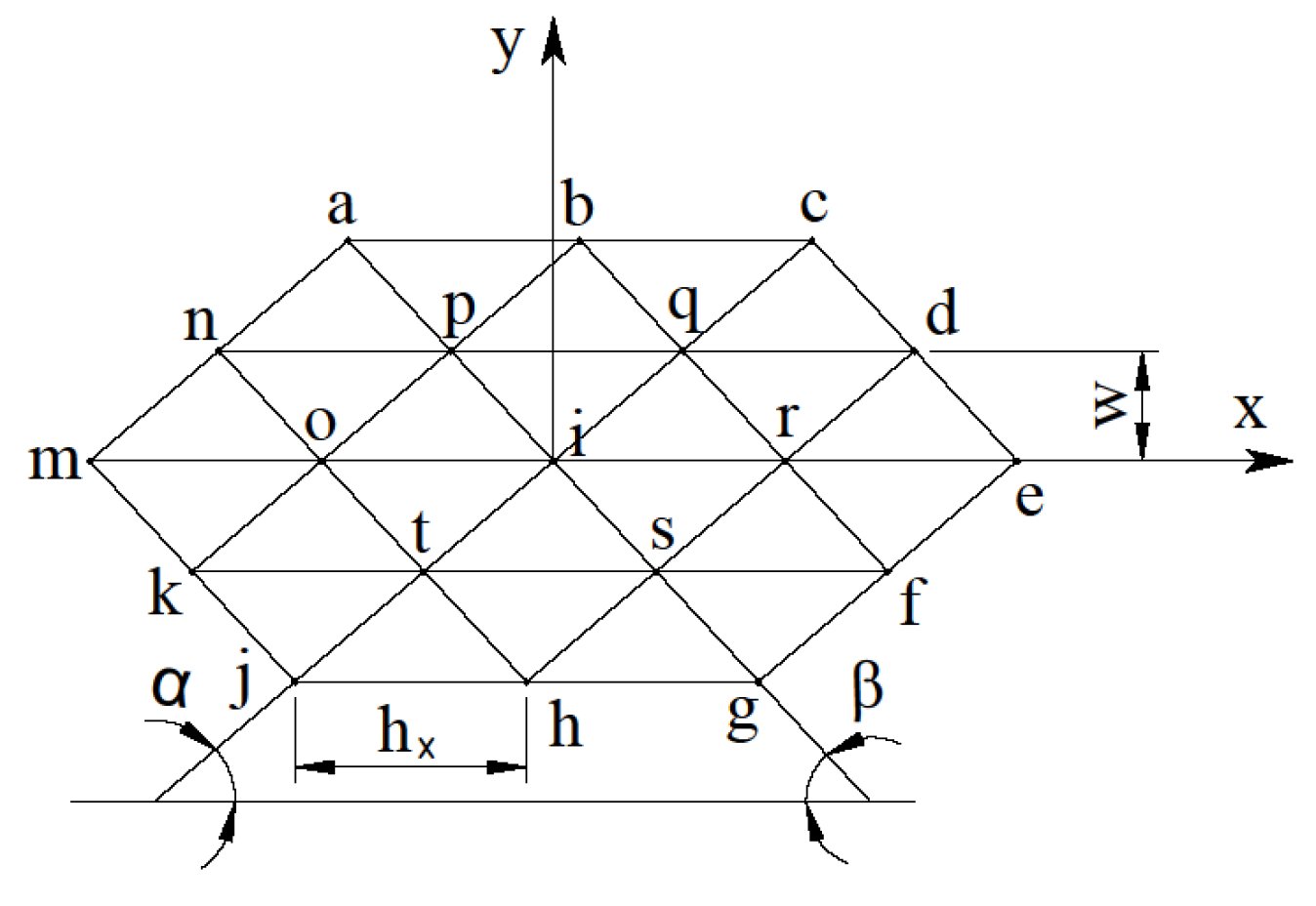
Figure 2 shows a fragment of a grid of scalene triangles:
For the
ith node of a grid of scalene triangles, equation (4) will take the form (without taking into account boundary conditions), which is given in [
17]:
In this case, mesh parameters
are defined as follows:
Angles
and
define parameters
A, B, C and
U:
The equation in the particular case for an isotropic plate for the i-th grid node is also written according to [
17] in the following form:
where
Thus, equations (7) and (10) differ only in expressions (8) and (11), respectively.
Appropriate boundary conditions at the edges of the plate must accompany the original equation (1). For continuously supported sides of the plate along the perimeter (
Figure 1), the boundary conditions have the form:
where
is the deflection at the
i-th node of the plate contour;
is normals to the edges of the plate (
Figure 1);
j=1,2 are the plate edge numbers.
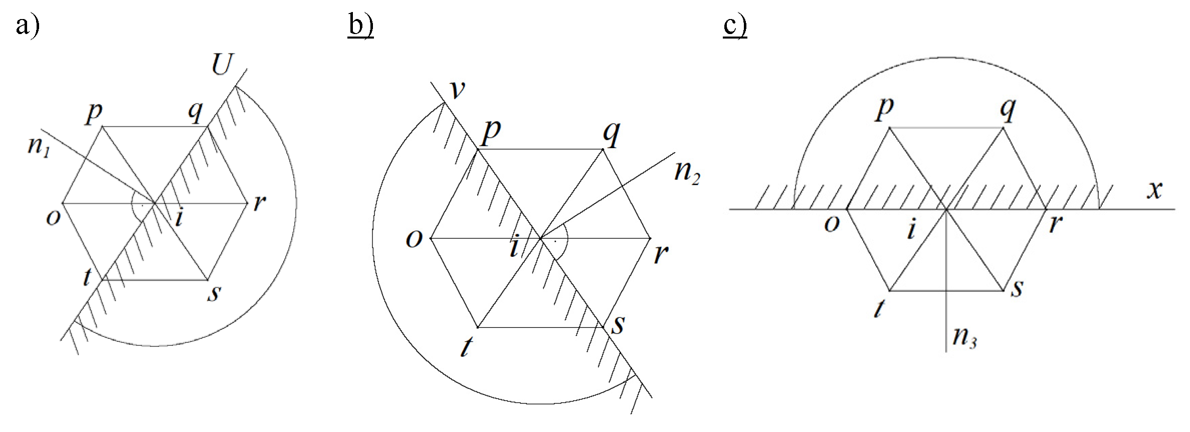
Boundary conditions (11) for the i-th node of the triangular mesh are written in finite differences in group form as follows:
For the left edge of the plate (
Figure 3a):
For the right edge of the plate (
Figure 3b):
The coefficients in expressions (13) – (15) took the following values:
for hinge-supporting edges of the plate;
for hard plate edges.
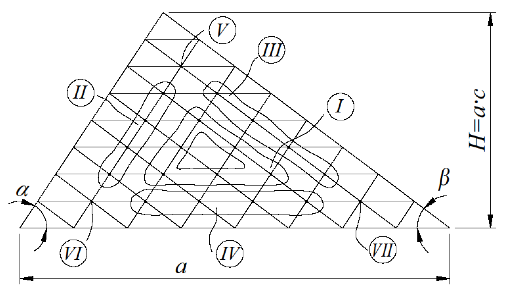
Boundary conditions (13) – (15) modify the main finite-difference equation for orthotropic triangular plates (7) and take the form of seven standard finite-difference equations for seven characteristic mesh nodes.
Figure 4 illustrates the numbering of typical grid equations.
With the number of mesh partitions (N=8) with continuous support of the edges along the perimeter of the triangular plate, we obtain 21 design (intra-circuit) nodes.
Figure 5 shows the numbering of some calculation nodes.
Finite-difference equations for all 21 computational nodes of the triangular mesh (
Figure 5) constitute a system of linear algebraic equations of the 21st order, which in matrix form has the form:
where
is a square matrix of the 21
st order,
is the vector of the desired deflection,
is the vector of free terms that considers the transverse load acting on the surface.
With a uniform distribution of the intensity of the transverse distributed load
q over the plate is:
where
is taken according to expression (3);
is the grid step along the axis (
Figure 5).
Thus, the algorithm proposed by the authors for calculating orthotropic plates consists in using expressions (2), (3), (7)-(9), (13)-(15) to implement equation (16).
Using the SMath Studio program [
27,
28], several research problems were solved based on expression (16). The influence of:
- type of boundary conditions (using coefficients),
- geometry of the plate (while setting the values of the angles α and β at the base of the plate), - orthotropy coefficients , determined by the formula (3), by the amount of nodal deflections ().
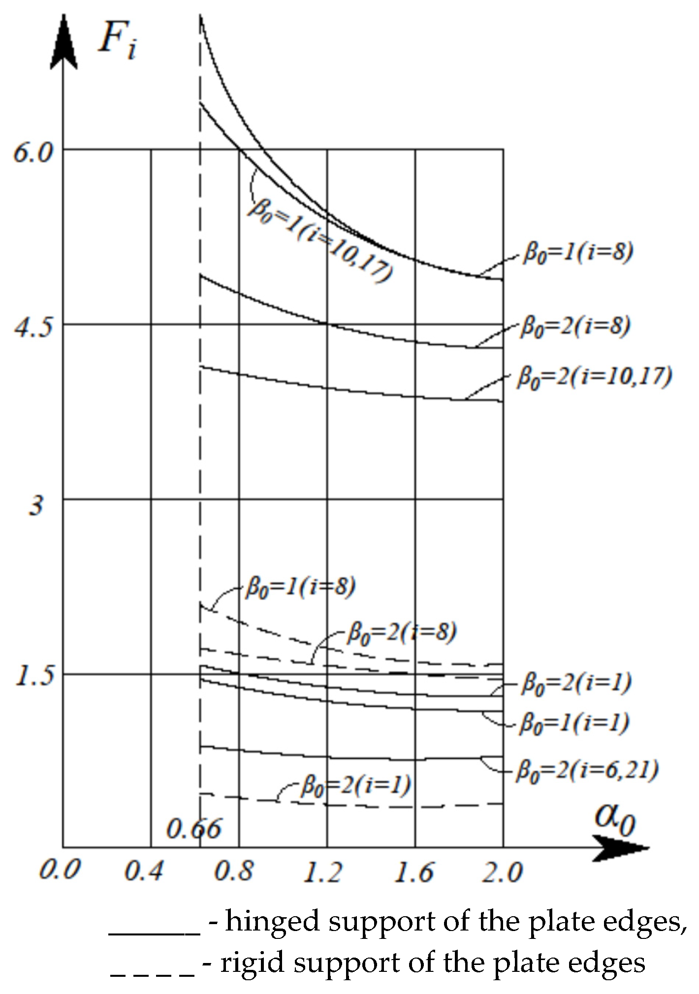
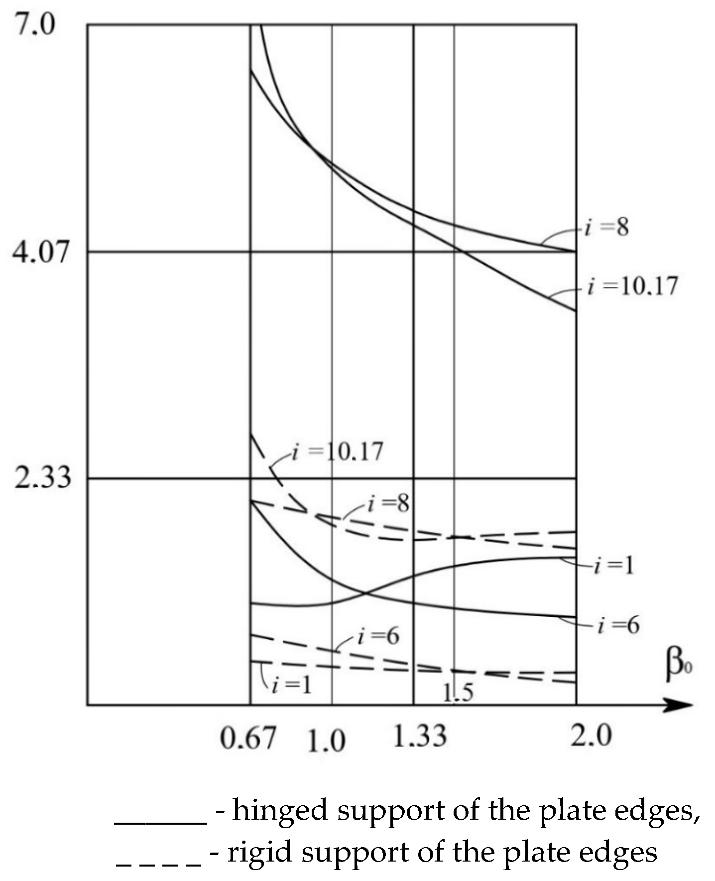
Figure 6 and
Figure 7 show the dependences of deflections at grid nodes δ=1, 6, 8, 10, 17, 21 (
Figure 5) for equilateral (α=β=60°) triangular orthotropic plates (at α
0-=0.66; 1; 1.5; 2.0 and β
0=0.5; 1; 1.5; 2.0) for rigid and simply supported edges with the number of mesh partitions N=8.
The calculations were conducted using (4) and (5). A rectangular grid of 1800 cells measuring 0.1 m × 0.2 m was constructed for a tray with 18.0 m × 2.0 m dimensions. At the entrance boundary corresponding to the first row of cells, it was assumed that the bottom was not eroded, which matched the entrance section of the tray reinforced with a cement crust in the laboratory experiment.
Table 2 and
Table 3 present the results of numerical calculations of equilateral triangular plates for various methods of pinning the edges.
- 1)
With an increase in the orthotropy coefficient α
0 (
Figure 6) for different β
0 and different boundary conditions, the deflections at the nodes monotonically decrease.
- 2)
With an increase in the orthotropy coefficient β
0 (
Figure 7) for constant values (α
0=1 ≈ const), the deflections at the plate nodes change according to a complex dependence.
- 3)
For an equilateral isotropic triangular plate (α0=2, β0=1), there are three axes of symmetry along its three medians. In this case, deflections are equal at nodes 1, 6, and 21.
- 4)
There is only one axis of elastic symmetry for equilateral orthotropic triangular plates. This axis of symmetry is the
y-axis. In this case, the deflections are equal only at nodes 6 and 21 (
Figure 6 and 7,
Table 2 and
Table 3).
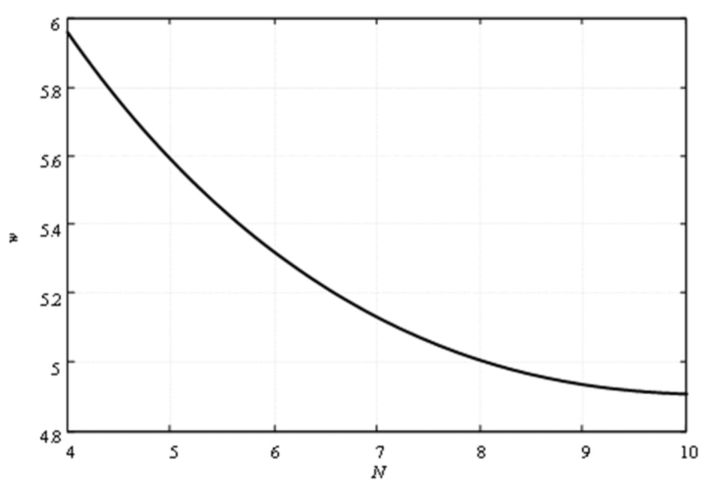
This problem was solved for two partition numbers of the sides of the plate as 4 and 8, for assessing the mesh convergence. The results were as follows:
- 1)
When the number of partitions is N = 4, the deflection in the middle of the triangle median equals to 5.96.
- 2)
When the number of partitions is N = 8, the deflection in the middle of the triangle median equals 4.97.
The resulting convergence graph (
Figure 8) is obtained using Richardson's extrapolation formula [
29].
To assess the reliability of the results presented, a finite element calculation of an equilateral triangular plate with hinged support along the perimeter was performed to determine the deflection in node 8 (
Figure 5) for
Pa,
Pa,
,
,
m,
kPa. The following value was obtained:
m. When switching to dimensionless coefficients, the deflection in the node with
,
is:
The uncertainty with the table value is , which indicates the acceptable accuracy of the described calculation algorithm based on the finite difference method.
4. Conclusions
The object of study is a transversely bent triangular plate made of orthotropic material, fixed along the edges of the plate under the action of a uniformly distributed load. An algorithm for simple engineering calculation of triangular orthotropic plates based on the finite difference method is presented, which makes it possible to perform manual or machine calculations in variant (or preliminary) design with sufficient accuracy. At the same time, the technical problem of boundary conditions for the edges of triangular plates was solved by the idea of paired exclusion of deflections of contour nodes, which arises when using a mesh of scalene triangles. When using the well-known rectangular grid, this problem does not arise.
In the proposed research method, the original 4th-order differential equations with variable orthotropy coefficients based on finite-difference approximation are replaced by grid equations using a grid of scalene triangles. As a result, a mathematical transition occurs to a system of linear algebraic equations, the solution of which results in deflections at the nodes of the applied mesh, and then the corresponding internal forces are calculated.
The results obtained allow us to draw the following conclusions.
The main and standard finite-difference equations for a mesh of scalene triangles (
Figure 2) are obtained, taking into account changes in the parameters of the geometry of the plates (angles α and β), boundary conditions (coefficients γ
1, δ
1, θ
1), orthotropy of the material (coefficients α
0, β
0), number of grid partitions N.
Boundary conditions for a mesh of scalene triangles are written in the original group (paired) form, which makes it possible to take into account the presence of oblique edges of irregular (non-equilateral) triangular plates;
Calculation of the deflection of equilateral (α=β=60°) orthotropic triangular plates (Equation 16) The deflection of equilateral (α=β=60°) orthotropic triangular plates was studied with the number of mesh partitions N=8, providing sufficient engineering accuracy.
The results of this study expand the range of problems to be solved for triangular orthotropic plates with their geometric asymmetry (oblique, scalene plates), which is the basis for further theoretical and practical developments in the mechanics of thin-walled structures.
Author Contributions
Conceptualization, S.A., V.T. and Z.N.; methodology, S.A. and M.B.; software, S.A., V.M. and V.T.; validation, M.B., and V. M.; formal analysis, S.A., V.T. and E.K.; investigation, V.T.; resources, E. K.; data curation, Z.N.; writing—original draft preparation, S.A., M.B., Z.N., V.M., V.T., and E.K.; writing—review and editing, S.A., M.B., Z.N., V.M., V.T., and E.K.; visualization, E. K. All authors have read and agreed to the published version of the manuscript.
Funding
This research was funded by the Ministry of Science and Higher Education of the Russian Federation within the framework of the state assignment No. 075-03-2022-010 dated 14 January 2022 (Additional agreement 075-03-2022-010/10 dated 09 November 2022, Additional agreement 075-03-2023-004/4 dated 22 May 2023), FSEG-2022-0010.
Conflicts of Interest
The authors declare no conflict of interest.
References
- Eröz, M. Stress analysis of a pre-stretched orthotropic plate with finite dimensions. Trans. Can. Soc. Mech. Eng. 2021, 45, 346–354. [Google Scholar] [CrossRef]
- Xu, Y.; Wu, Z. Exact solutions for rectangular anisotropic plates with four clamped edges. Mech. Adv. Mater. Struct. 2022, 29, 1756–1768. [Google Scholar] [CrossRef]
- Yu, Q. A hierarchical wavelet method for nonlinear bending of materially and geometrically anisotropic thin plate. Commun. Nonlinear Sci. Numer. Simul. 2021, 92. [Google Scholar] [CrossRef]
- Chen, X.; Nie, G.; Zhong, Z. Research Progress on Static and Dynamic Problems of Variable Angle Tow Composite Plates and Shells. Chinese Q. Mech. 2023, 44, 1–14. [Google Scholar] [CrossRef]
- Nowinski, J.L.; Ismail, I.A. Large oscillations of an anisotropic triangular plate. J. Franklin Inst. 1965, 280, 417–424. [Google Scholar] [CrossRef]
- Sathyamoorthy, M. Effects of large amplitude and transverse shear on vibrations of triangular plates. J. Sound Vib. 1985, 100, 383–391. [Google Scholar] [CrossRef]
- Jaunky, N.; Knight, N.F.; Ambur, D.R. Buckling analysis of general triangular anisotropic plates using polynomials. AIAA J. 1995, 33, 2414–2417. [Google Scholar] [CrossRef]
- Jaunky, N.; Knight Jr., N.F.; Ambur, D.R. Buckling analysis of general triangular anisotropic plates using polynomials. In Proceedings of the Collection of Technical Papers - AIAA/ASME/ASCE/AHS/ASC Structures, Structural Dynamics and Materials Conference; 1995; Vol. 4, pp. 2647 – 2654.
- Jaunky, N.; Knight Jr., N. F.; Ambur, D.R. Optimal design of general stiffened composite circular cylinders for global buckling with strength constraints. Compos. Struct. 1998, 41, 243–252. [Google Scholar] [CrossRef]
- Jaunky, N.; Knight N.F., J.; Ambur, D.R. Optimal design of grid-stiffened composite panels using global and local buckling analyses. In Proceedings of the 37th AIAA/ASME/ASCE/AHS/ASC Structure, Structural Dynamics and Materials Conference; 1996; pp. 2315–2325.
- Saliba, H.T. Free vibration of simply supported general triangular thin plates: An accurate simplified solution. J. Sound Vib. 1996, 196, 45–57. [Google Scholar] [CrossRef]
- Xiang, Y. Buckling of triangular plates with elastic edge constraints. Acta Mech. 2002, 156, 63–77. [Google Scholar] [CrossRef]
- Dayyani, I.; Moore, M.; Shahidi, A. Unilateral buckling of point-restrained triangular plates. Thin-Walled Struct. 2013, 66, 1–8. [Google Scholar] [CrossRef]
- Askari, H.; Saadatnia, Z.; Esmailzadeh, E.; Younesian, D. Multi-frequency excitation of stiffened triangular plates for large amplitude oscillations. J. Sound Vib. 2014, 333, 5817–5835. [Google Scholar] [CrossRef]
- Esmailzadeh, E.; Younesian, D.; Askari, H. Energy balance methods. Solid Mech. its Appl. 2019, 252, 73–122. [Google Scholar] [CrossRef] [PubMed]
- Saadatnia, Z.; Rahnamayan, S.; Esmailzadeh, E. Vibration Analysis and Multi-Objective Optimization of Stiffened Triangular Plate. In Proceedings of the Proceedings of the ASME Design Engineering Technical Conference; p. 20148.
- Akhmediev, S.K.; Zhakibekov, M.E.; Kurokhtina, I.N.; Nuguzhinov, Z.S. Numerical study of the stress-strain state of structures such as thin triangular plates and plates of medium thickness. Struct. Mech. Calc. Struct. 2015, 259, 28–33. [Google Scholar]
- Wang, Q.; Xie, F.; Liu, T.; Qin, B.; Yu, H. Free vibration analysis of moderately thick composite materials arbitrary triangular plates under multi-points support boundary conditions. Int. J. Mech. Sci. 2020, 184. [Google Scholar] [CrossRef]
- He, D.; Liu, T.; Qin, B.; Wang, Q.; Zhai, Z.; Shi, D. In-plane modal studies of arbitrary laminated triangular plates with elastic boundary constraints by the Chebyshev-Ritz approach. Compos. Struct. 2021, 271, 114138. [Google Scholar] [CrossRef]
- Akhmediyev, S.K.; Khabidolda, O.; Vatin, N.I.; Yessenbayeva, G.A.; Muratkhan, R. PHYSICAL AND MECHANICAL STATE OF CANTILEVER TRIANGULAR PLATES. J. Math. Mech. Comput. Sci. 2023, 118, 64–73. [Google Scholar] [CrossRef]
- Grigorenko, O.Y.; Borisenko, M.Y.; Boichuk, O. V; Vasil’eva, L.Y. Free Vibrations of Triangular Plates with a Hole. Int. Appl. Mech. 2021, 57, 534–542. [Google Scholar] [CrossRef]
- Yang, Y.; An, D.; Xu, H.; Li, P.; Wang, B.; Li, R. On the symplectic superposition method for analytic free vibration solutions of right triangular plates. Arch. Appl. Mech. 2021, 91, 187–203. [Google Scholar] [CrossRef]
- Upadhyay, V.; Bhar, A. FINITE-ELEMENT ANALYSIS OF HYBRID GRID-STIFFENED HONEYCOMB CORE SANDWICH PLATES FOR STRUCTURAL PERFORMANCE ENHANCEMENT. Compos. Mech. Comput. Appl. An Int. J. 2023, 14, 79–97. [Google Scholar] [CrossRef]
- Ambartsumian, S.A. On the theory of bending of anisotropic plates and shallow shells. J. Appl. Math. Mech. 1960, 24, 500–514. [Google Scholar] [CrossRef]
- Ambartsumian, S.A. Membrane Theory of Plates. In Foundations of Engineering Mechanics; Springer International Publishing, 2021; pp. 73–103.
- Poniatovskii, V. V. On the theory of bending of anisotropic plates. J. Appl. Math. Mech. 1964, 28, 1247–1254. [Google Scholar] [CrossRef]
- Brezinski, C. Some pioneers of extrapolation methods. In The Birth of Numerical Analysis; WORLD SCIENTIFIC, 2009; pp. 1–22 ISBN 9789812836267.
- Nuzhdin, L.; Mikhailov, V.; Rezyapkin, V. Modeling and analysis of the pile cluster foundation in SCAD and SMath Studio. In Proceedings of the 16th Asian Regional Conference on Soil Mechanics and Geotechnical Engineering, ARC 2019; 2020.
- Zlatev, Z.; Dimov, I.; Faragó, I.; Georgiev, K.; Havasi, Á. Stability of the Richardson Extrapolation combined with some implicit Runge–Kutta methods. J. Comput. Appl. Math. 2017, 310, 224–240. [Google Scholar] [CrossRef]
- Tian Y, Zhao W, Yu C, Gang X, Lu P, Yue Q. Investigations on Flexural Strength of a Columnar Saline Model Ice under Circular Plate Central Loading. Water (Switzerland). 2023;15(19). [CrossRef]
- Zheng Y, Zhou Y, Jin R, Mu Y, He M, Zhao L. Experimental Study on Submerged Horizontal Perforated Plates under Irregular Wave Conditions. Water (Switzerland). 2023;15(16). [CrossRef]
- Gravanis E, Sarris EN. A New Analytical Method for Calculating Subsidence Resulting by Fluid Withdrawal from Disk-Shaped Confined Aquifers. Water (Switzerland). 2023;15(18). [CrossRef]
- Miao S, Zhan X, Yuan Y, Jia L. A Study of the Mechanical Properties of Polyester Fiber Concrete Continuous Rigid Frame Bridge during Construction. Buildings. 2023;13(11):2849. [CrossRef]
- Xue H, Zhao K, Xia F, Wang G, Shen A. Numerical Investigation of the Ultimate Load-Carrying Capacity of Square Concrete-Filled Steel Tube Columns Considering Initial Stresses Generated during Construction. Buildings. 2023;13(11):2830. [CrossRef]
- Li P, Wang S, Zhang M, Huang Z. Supporting Structure of Steel Corrugated Plate-Mold Bag Concrete and Its Application in a Circular Shaft. Appl Sci. 2023;13(23):12937. [CrossRef]
|
Disclaimer/Publisher’s Note: The statements, opinions and data contained in all publications are solely those of the individual author(s) and contributor(s) and not of MDPI and/or the editor(s). MDPI and/or the editor(s) disclaim responsibility for any injury to people or property resulting from any ideas, methods, instructions or products referred to in the content. |
© 2023 by the authors. Licensee MDPI, Basel, Switzerland. This article is an open access article distributed under the terms and conditions of the Creative Commons Attribution (CC BY) license (http://creativecommons.org/licenses/by/4.0/).
