1. Introduction
With the rapid development of mechanical technology, the complexity and performance of steel types have also increased. Wear resistance and fatigue resistance of the steel are also getting more attention. JIS SUJ2 steel is a high-quality alloy steel. The advantages are good hardenability, wear resistance and comprehensive mechanical properties [
1,
2]. It is suitable for mechanical parts such as ball bearings, guides and rollers.
SUJ2 has a carbon content of up to 1.0 % and is a hypereutectoid steel. As observed by the Fe-Fe3C equilibrium phase diagram, primary carbides during casting can be easily formed, which makes processing difficult. Therefore, an annealing or spheroidizing process is required to disperse large carbides to facilitate processing and forming. Moreover, retained austenite in SUJ2 is easy to observe after the heat treatment process, resulting in nonuniform-hardness structures. In addition, the retained austenite is an unstable phase, which tends to cause uneven deformation of the bearing steel. The parts need to eliminate the retained austenite to improve the mechanical properties of SUJ2 after heat treatment [
3,
4,
5].
The fatigue behavior of induction-hardened parts depends on the combination of hardening depth and distribution of residual compressive stress in the case [
6,
7]. The influence of induction hardening parameters on fatigue life should be considered during the design to reduce manufacturing costs. Therefore, it is very important to optimize the induction hardening process parameters according to the residual stress distribution [
8,
9]. Y. Hu and J. W. Gao [
10,
11] et al. studied the fatigue life of S38C shaft steel after induction quenching. The results show that the remaining life of a damaged part with residual compressive stress is more than three times that of a part without residual compressive stress. J. Komotori and M. Hayama [
12,
13] et al. performed induction hardening on low alloy steel to obtain different hardening depths and hardness. The results showed that the stability of the compressive residual stress depends on hardness. And thicker hardened layer will improve the fatigue strength.
Induction-hardening processed parts ultimately obtain a combination of high case hardness and internal toughness, which greatly increases wear and fatigue resistance [
14,
15,
16,
17,
18,
19,
20,
21]. In addition to the residual stress distribution of the hardened layer, H. Kristoffersen studied the effect of parameter control of induction hardening treatment on the residual stress distribution on the steel surface [
22]. In the successfully hardened place after induction quenching, compressive residual stress will be obtained due to phase change. However, the heat-affected zone caused by the temperature gradient shows tensile residual stress.
Therefore, this paper focuses on induction hardening of JIS SUJ2 with different microstructures, uses X-ray diffraction analysis to measure surface residual stress, and discusses how microstructure differences affect the distribution behavior of surface residual stress and retained austenite.
2. Materials and Methods
2.1. Specimens preparation
This study uses SUJ2 bearing steel in rod with a diameter of 17 mm and a length of 100 mm. After quenching and tempering with a salt bath to obtain different microstructures, the surface layer was re-quenched by induction method.
Table 1 lists the chemical composition of the JIS SUJ2 specimens analyzed by using an optical emission spectrometer (OES).
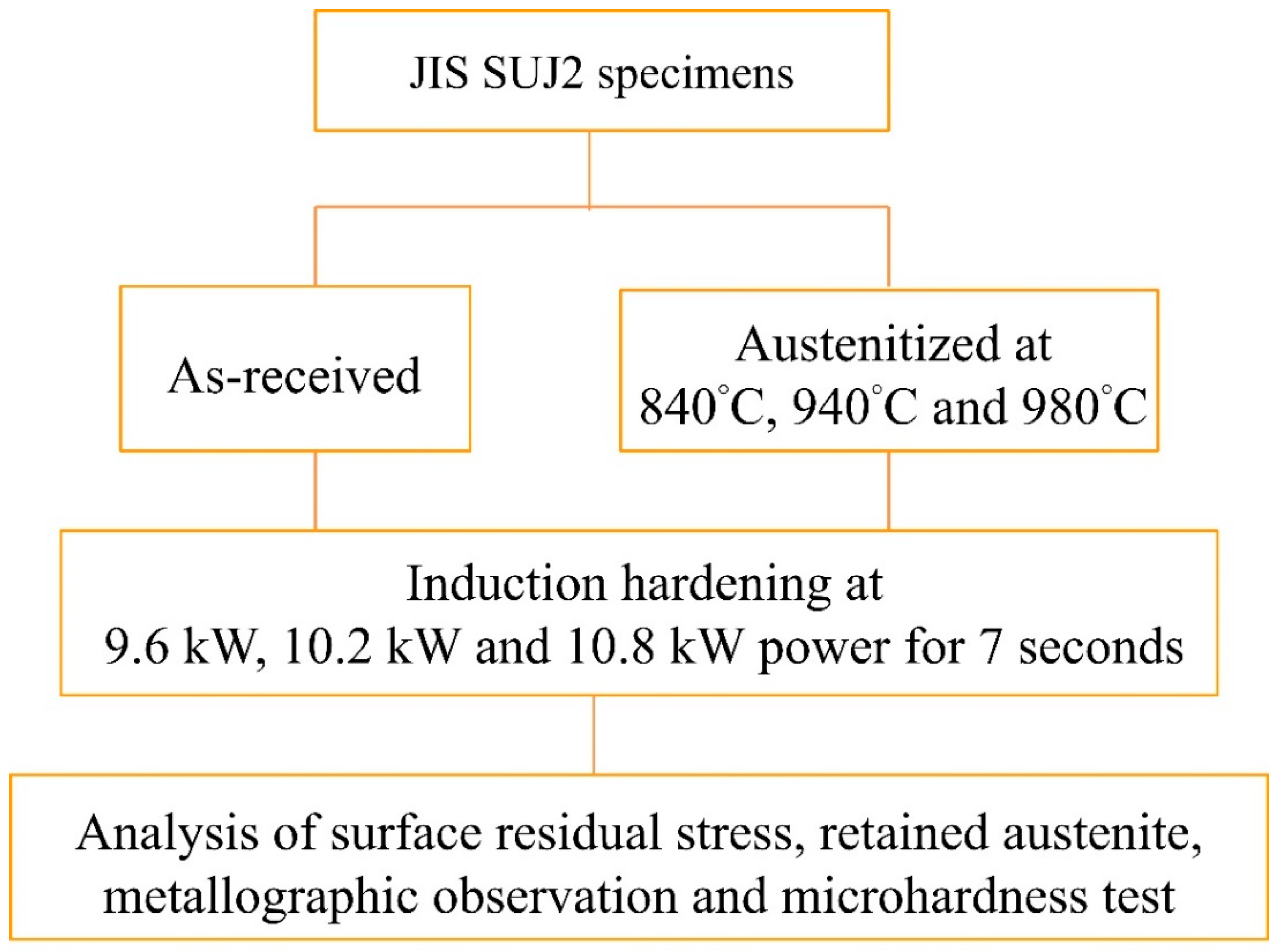
After the heat treatment was completed, the surface residual stress of the specimens was measured, and the hardened case was subjected to microstructure observation, microhardness (HV) measurement and X-ray diffraction analysis. The graphical abstract of this study is shown in
Figure 1.
2.2. Heat treatment process
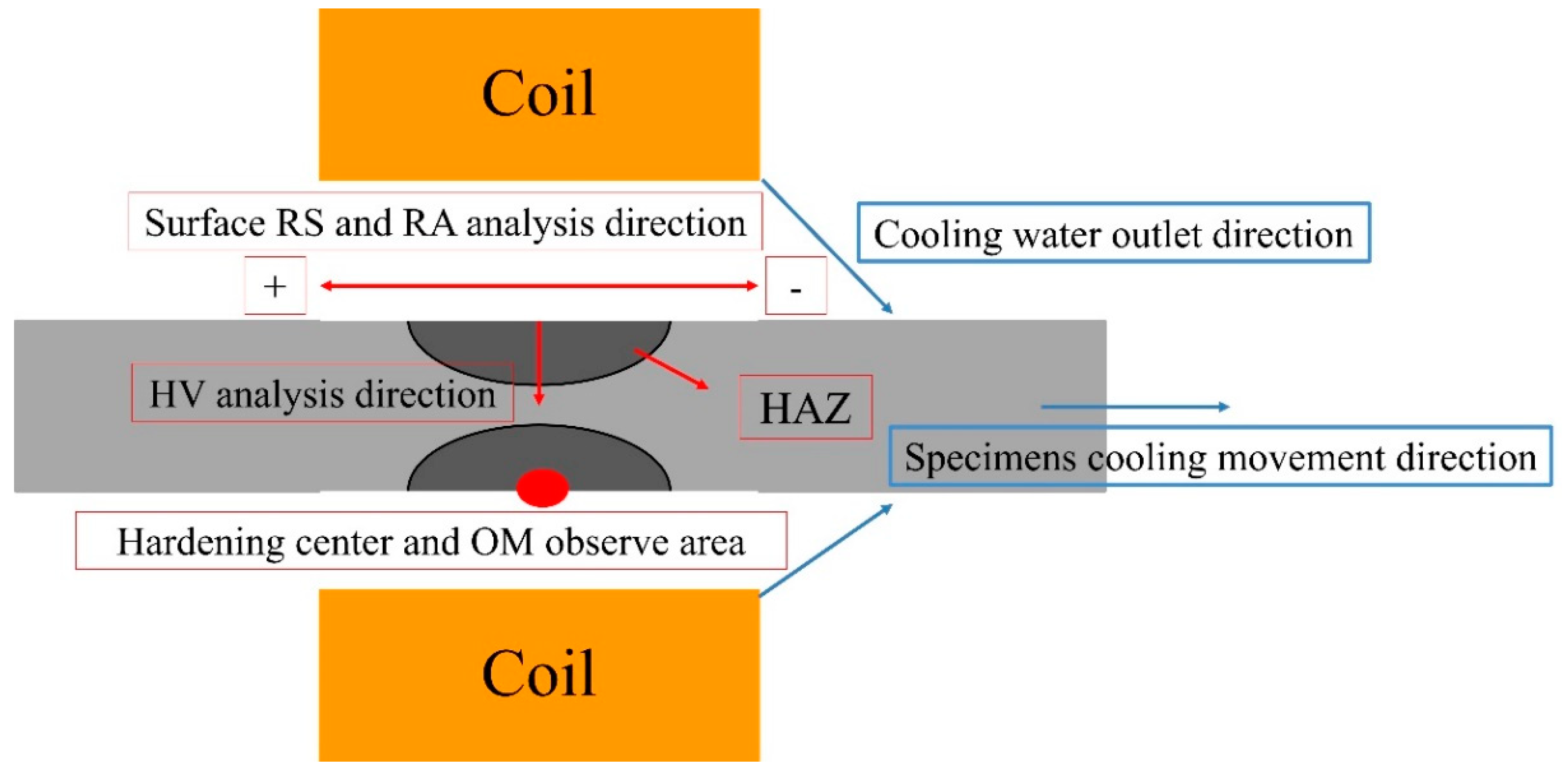
Specimens were austenitized at three different temperatures of 840 °C, 940 °C and 980 °C for 1 hour in salt bath, then quenched in oil at 90 °C and then tempered at 180 °C for 1 hour. The specimens of the as-received state (spheroidized) and after quenching and tempering at three different austenitizing temperatures were subjected to induction hardening. The induction hardening conditions were positional heating at 9.6 kW, 10.2 kW and 10.8 kW for 7 seconds and cooling with a continuous water source, respectively. The experiment device schematic diagram is shown in
Figure 2.
2.3. Analytical methods
2.3.1. Microstructure observation
Use a grinding wheel cutting machine to capture the longitudinal section of the heated area of specimens. After mounting, ground to #2000 in turn, then polished with 0.05 μm alumina powder and etching with Nital (95 ml alcohol + 5 ml nitric acid). The differences in microstructure after heat treatment were observed with an optical microscope (Olympus-BX60M).
2.3.2. Hardness test
In terms of the hardness test, a Rockwell hardness tester (Matsuzawa Seiki MARK-M2) was used to measure the hardness (HRC) values of the quenching and tempering specimens at three different austenitizing temperatures and as-received. Each specimen was tested five times to obtain the average hardness value. To determine the effective case depth, the Vickers hardness tester (Matsuzawa MXT50) was used to measure the microhardness (HV) values from the induction-hardened case to the core area. The microhardness test is measured with a 100 g load and the pressure time is 10 seconds. A microhardness curve from the induction-hardened case to the core area is established.
2.3.3. X-ray diffraction
The residual stress and content of retained austenite were measured with a portable X-ray diffractometer (Pulstec, μ-X360s), applying the measuring principle of the single incident angle method (cos𝛼 method). μ-X360s with a target material of Cr, a voltage of 30 kV, a current of 1 mA, and a diffraction range of 35° for residual stress and 0° for retained austenite analysis[
23,
24,
25,
26,
27,
28,
29,
30]. The value of residual stress was calculated using the following two equations showing in Eq. 1 and Eq. 2. The friction of retained austenite (γ %) in microstructure was calculated using the equation, γ % = (Iγ/Rγ)/[(Iγ/Rγ) + (Iγ/Rγ)] * 100 %, where Iγ and Iγ are the integrated intensity for austenite and ferrite, respectively, and Rγ and Rγ are the theoretical relative in-tensity for austenite and ferrite, respectively. Surface residual stress and retained austenite content measurement were performed.
For the hardened center and heat-affected zone obtained after induction hardening of specimens, measure the surface residual stress value and retained austenite content at intervals of 4 mm.
3. Results and discussion
3.1. Microstructure observation
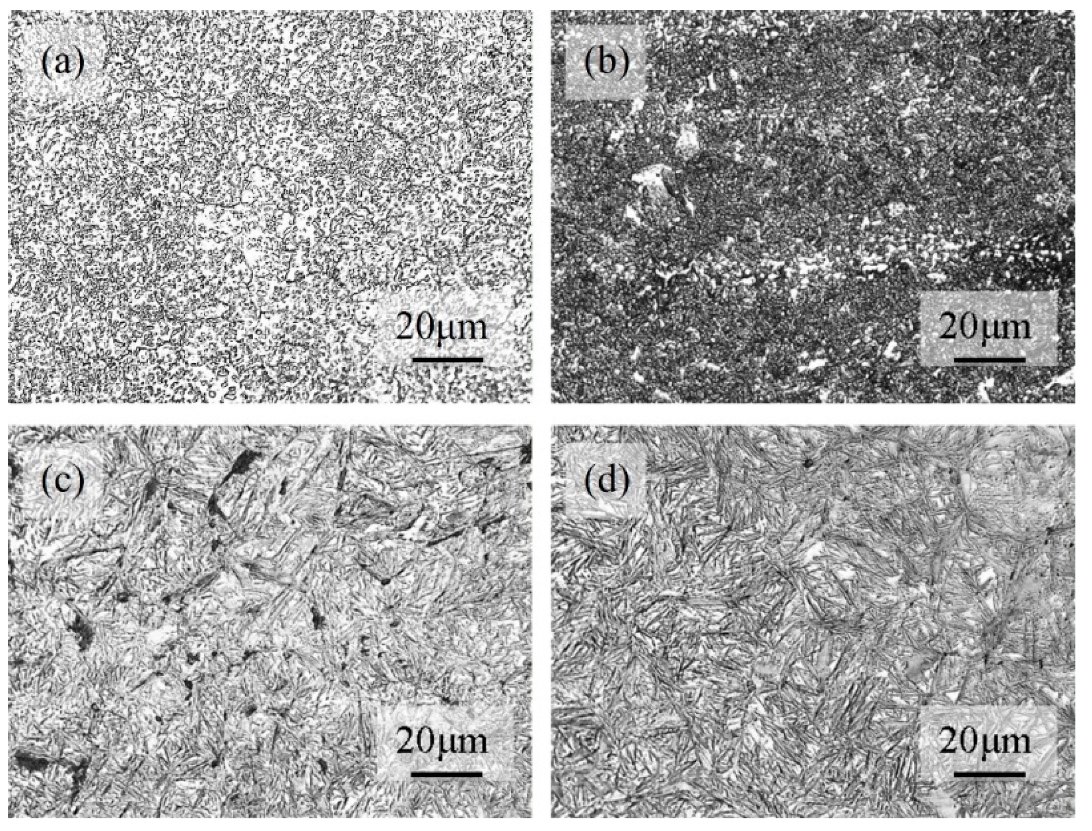
The microstructure of the SUJ2 specimen after different heat treatments is shown in
Figure 3.
Figure 3 (a) shows the microstructure of the as-received SUJ2 steel, in which the spheroidal cementite is uniformly dispersed in the ferrite matrix.
Figure 3 (b) shows that the SUJ2 steel is austenitized at 840 °C followed by oil quench and then tempered at 180 °C, in which the cementite is not completely solid-solved and dispersed in the tempered martensite matrix. This is because under the condition that the carbon content is close to 1.0 wt%, the austenitizing temperature of 840 °C is still close to the Acm line, so the benefit of cementite solid-solved into the austenite phase is not significant. If the austenitizing temperature is increased, the proportion of cementite solid-solved in the martensite can be increased.
Figure 3 (c) and (d) show the structure of the SUJ2 steel via 940 and 980 °C, followed by oil quench and tempered at 180°C, in which the structure of different volumes of retained austenite and slim tempered martensite is observed. The result shows that increase in the austenitizing temperature, the volume of retained austenite will increase.
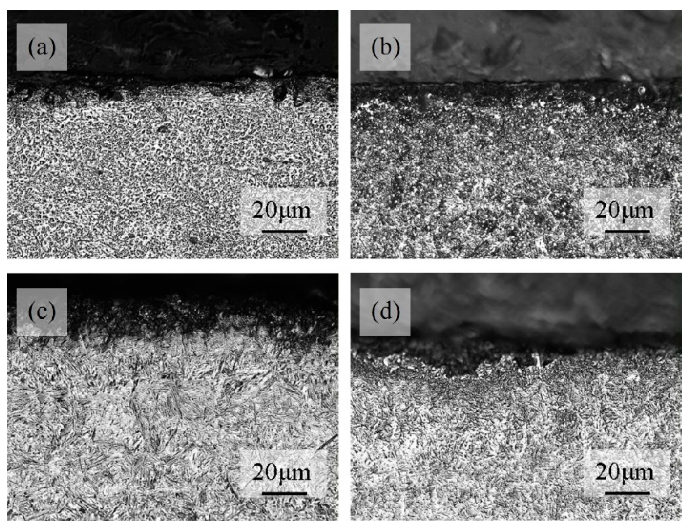
Figure 4 shows the microstructure of the hardened case after induction hardening of the SUJ2 specimen in
Figure 3.
Figure 4 (a) shows that if the spheroidized structure was hardened, the microstructure of the case is composed of the cementite is not completely solid-solved and dispersed in the tempered martensite matrix. This result shows that the temperature that can be reached when induction hardening is performed at an output power of 10.8 kW may be close to the Acm line. The amount of cementite solid-solved in austenite is affected by temperature and time. During induction hardening treatment, the temperature holding time is very short, so the temperature raised during induction must be higher to promote the solid-solved effect of cementite.
Figure 4 (b) shows the microstructure of the re-hardened case of the specimen in
Figure 3 (b). The specimen was first subjected to austenitized at different temperatures and then subjected to induction hardening. The result shows the content of cementite in the induction re-hardened case is less than that specimen was only held in a salt bath at 840°C. Due to the increase in the amount of carbon atoms in the lattice. The increase in the proportion of the cementite solid-solved into the martensite, will increase the content of retained austenite after re-hardened.
Figure 4 (c) and (d) show the martensite of the case region is finer than the martensite shown in
Figure 3 (c) and (d). This is because during the induction re-quenching process, due to the continuous cooling method, the temperature of the austenite is shorter, resulting in a shorter time for grain growth after recrystallization, so the grain size is smaller.
3.2. Hardness analysis
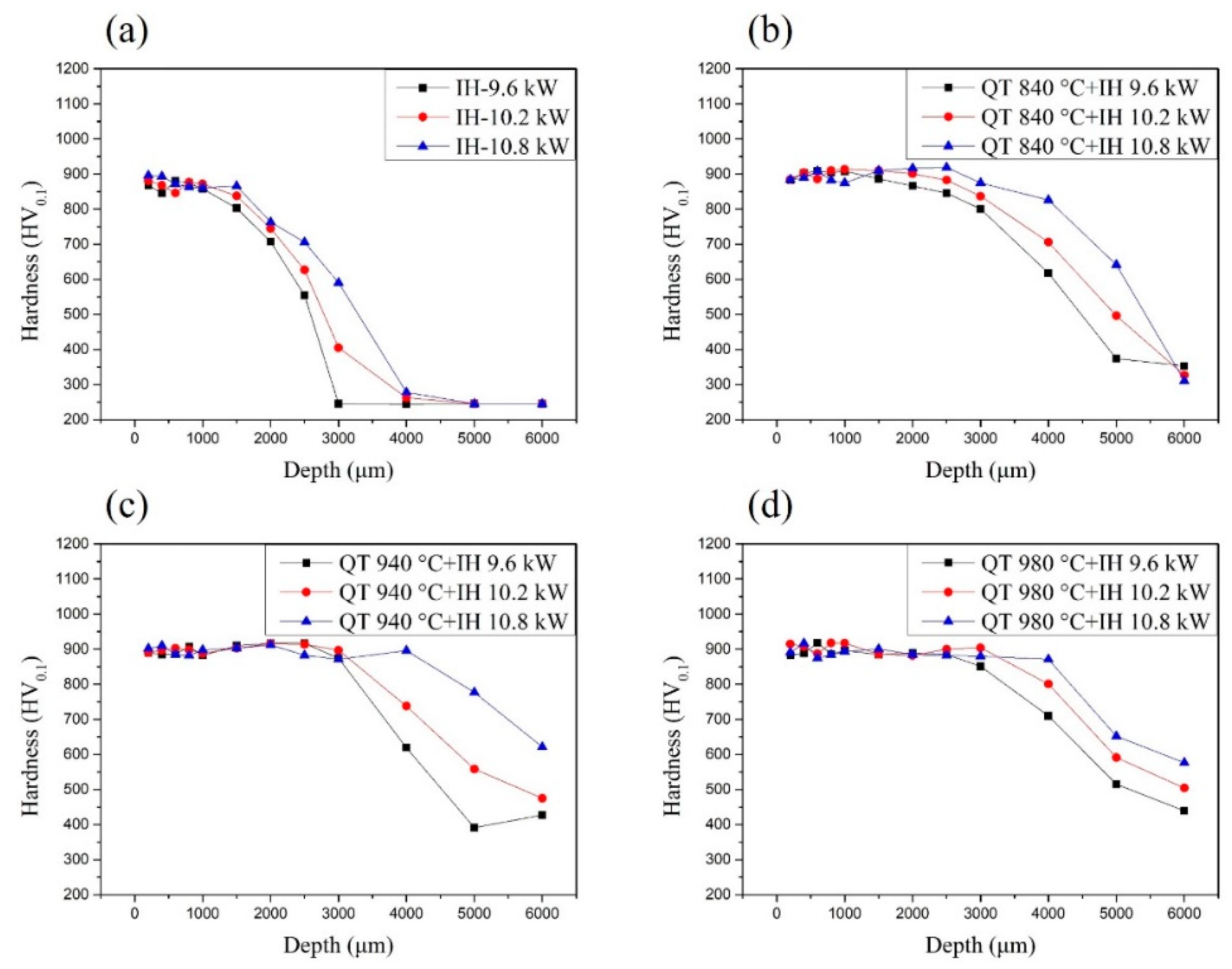
The microhardness curve of the specimen after different heat treatments which were induction hardened is shown in
Figure 5. According to the needs of industrial use, the depth of 550 HV is set as the effective case depth.
Figure 5 (a) shows that the spheroidized structure was hardened by the induction hardening method with 9.6 kW, the hardness value of the case is 860 HV
0.1, and the effective case depth is 2.5 mm. With the induction power increased to 10.2 kW, the hardness value of the case is 880 HV
0.1, and the effective case depth is 2.8 mm. When the induction power is increased to 10.8 kW, the hardness value of the case is 900 HV
0.1, and the effective case depth is 3.2 mm. These results show that the induction power increase, the hardness value of the case and the effective case depth will increase relatively. As the power increases, the holding temperature that can be achieved during induction hardening will be higher, so the hardness value and hardening depth will increase.
Figure 5 (b) ~ (d) shows specimen will have a deeper effective case depth in which the structure before induction hardening is martensite. For comparison, we discussed the effective case depth of the specimens that were first treated with different austenitizing temperature treatments and used an induction power of 9.6 kW for re-hardening. The hardness values of the case are all about 900 HV
0.1. The effective case depth of austenitized at 840 °C and re-hardened with induction power is 9.6 kW specimen is 4.2 mm. The effective case depth of austenitized at 840 °C and re-hardened with induction power is 9.6 kW specimen is 4.5 mm. The effective case depth of austenitized at 840 °C and re-hardened with induction power is 9.6 kW specimen is 5.0 mm. This result shows that the effective case depth of induction-hardened specimens was increased with the austenitized temperature increase. The hardness value obtained by first quenching and tempering to obtain the martensite structure and then induction hardening is higher than the hardness value obtained by direct induction hardening of the spheroidized structure. However, the hardness value obtained by induction re-hardening will not increase due to the increase in austenitized temperature before induction re-hardening.
3.3. X-ray diffraction analysis
3.3.1. Residual stress analysis
The surface residual stress data of the specimen austenitized at 840 °C, 940 °C and 980 °C which were detected by the X-ray diffractometer (Pulstec, μ-X360s) is shown in
Table 2. Indicating that residual compressive stress was observed in the as-received SUJ2 specimen. The surface residual compressive stress value of the as-received SUJ2 specimen is -77 MPa. However, the surface residual stress appears a tensile state was observed in the specimen austenitized at 840 °C, 940 °C and 980 °C. The surface residual tensile stress value of the specimen austenitized at 840 °C is 106 MPa, austenitized at 940 °C is 118 MPa and austenitized at 980 °C is 130 MPa. This may be due to the use of a BaCl salt bath for heat treatment. For example, we know that during the quenching stage of steel heat treatment, the structure transforms into martensite due to phase changes. This type of structure changes from BCC to BCT structure, and the volume of parts will expand. The surface residual stress will exhibit a tensile state. In carburizing heat treatment, because the diffusion direction of carbon atoms is inward, the driving force of the concentration gradient may make the surface residual stress state tend to be compressive. During the salt bath heat treatment process, carbon atoms cannot be effectively prevented from moving to the surface. The diffusion direction of carbon atoms in the specimens is towards the interface between the salt bath and the specimens. Then the surface residual stress tends to be in a tensile state. In addition, the retained austenite was observed at 940 and 980 °C. The content of the retained austenite austenitized at 940 and 980 °C are 5.1 and 9.0 %.
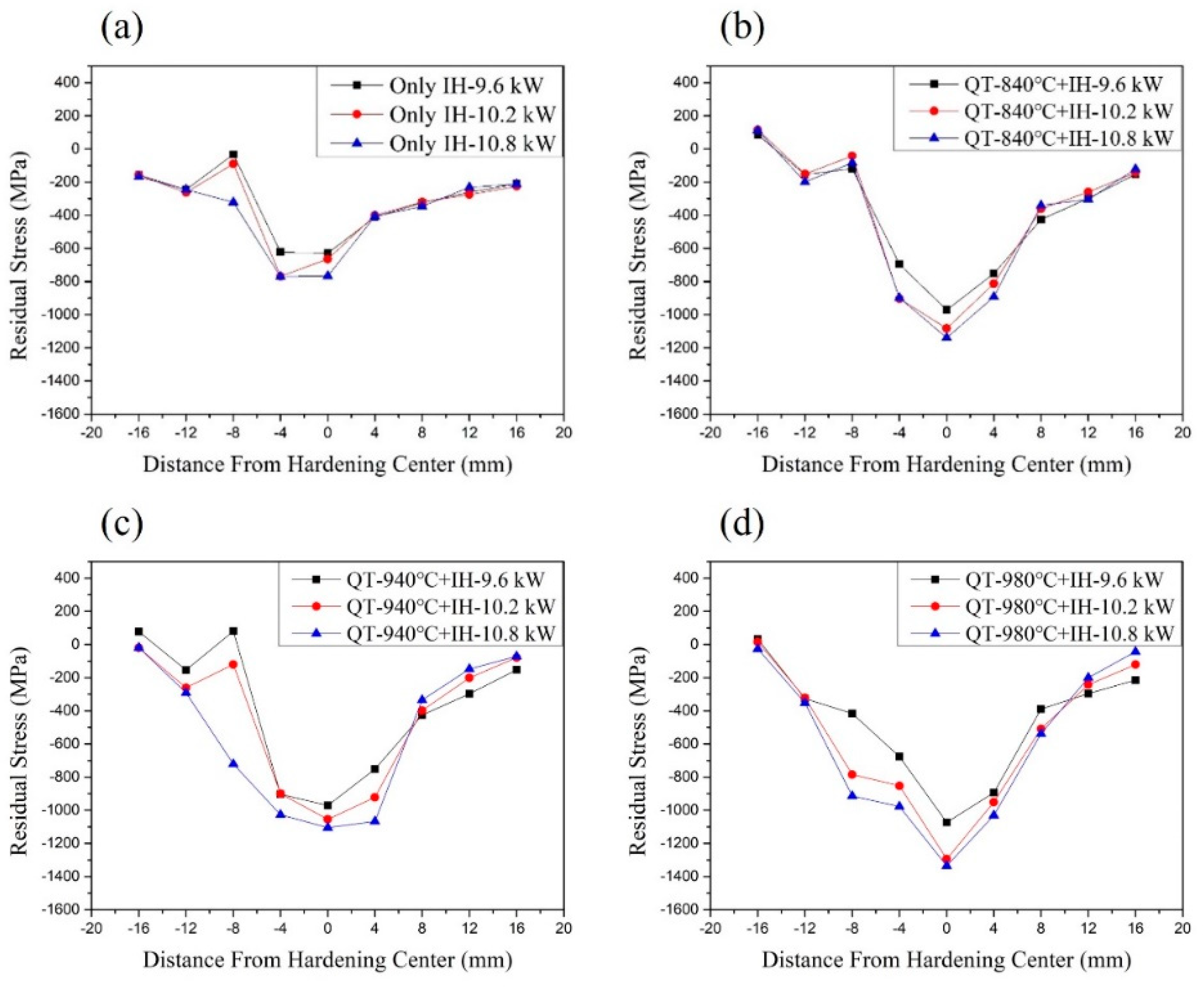
Figure 6 (a) shows the surface residual stress data of the as-received SUJ2 specimen after induction hardening. It has the highest surface residual compressive stress value at the hardening center, which can be up to -750 MPa. This is because the hardened center by induction will be subject to more severe temperature changes, so the phase transformation caused by the supercooling driving force and the thermal stress caused by the temperature gradient is more effective. As the distance from the hardening center increases, the residual compressive stress value will gradually decrease. As the induction power increases, the surface residual compressive stress value will increase relatively. These results are also related to the temperature gradient during induction hardening. The specimen was hardened by the induction hardening method with 9.6 kW, the surface residual compressive stress value of the hardening center is -629 MPa. With the induction power increased to 10.2 kW, the surface residual compressive stress value of the hardening center is -663 MPa. With the induction power increased to 10.8 kW, the surface residual compressive stress value of the hardening center is -766 MPa.
Figure 6 (b) ~ (d) shows that it has a deeper stress influence range in which the structure before induction hardening is martensite. The maximum residual compressive stress value in the hardened area will also increase with the austenitized temperature increase. This is because, during the induction hardening process, the specimen is raised to an extremely high temperature in a short time and then cooled rapidly, resulting in a stronger thermal stress effect. The central area of induction hardening is most affected by thermal stress and exhibits the maximum value of residual compressive stress. And the phase transformation of the martensite structure caused more internal stress due to re-hardening treatment than spheroidized structure transform to martensite. For comparison, we discussed the maximum residual compressive stress value of the specimens that were first treated with different austenitizing temperature treatments and used an induction power of 9.6 kW for re-hardening. The maximum surface residual compressive stress value of austenitized at 840 °C and re-hardened with induction power is 9.6 kW specimen is -956 MPa. The maximum surface residual compressive stress value of austenitized at 940 °C and re-hardened with induction power is 9.6 kW specimen is -977 MPa. The maximum surface residual compressive stress value of austenitized at 980 °C and re-hardened with induction power is 9.6 kW specimen is -1073 MPa.
The residual compressive stress can help offset the tensile stress that may occur when the parts are used, so residual compressive stress is considered beneficial to the wear resistance of the product. To meet the needs of industrial use, the surface residual stress specifications of the hardened zone and heat-affected zone must be set to -400MPa which is set as the effective stress influence range. The effective stress influence range at the surface should be compared. The effective stress influence range of austenitized at 840 °C and re-hardened with induction power is 9.6 kW specimen is about 13 mm. The effective stress influence range at the surface should be compared. The effective stress influence range of austenitized at 940 °C and re-hardened with induction power is 9.6 kW specimen is about 14 mm. The effective stress influence range of austenitized at 980 °C and re-hardened with induction power is 9.6 kW specimen is about 16 mm.
3.3.2. Retained austenite analysis
The retained austenite is an unstable microstructure and affects the stability of the subsequent use of the parts. Without taking into account the difference in alloy content, carbon steel with a carbon content of more than 0.7 wt % will obtain the martensite structure after quenching, and it is usually accompanied by retained austenite. During use, if these retained austenite are subjected to mechanical or thermal stress, they will easily transform into martensite, resulting in changes in shape and size (distortion). This will indirectly lead to premature failure of other parts and cause unnecessary external losses.
The surface retained austenite content data of the specimen austenitized at 840 °C, 940 °C and 980 °C which were detected by the X-ray diffractometer (Pulstec, μ-X360s) is shown in
Table 2. The results show that no retained austenite content was observed in the SUJ2 specimens which were as-received and austenitized at 840 °C. The surface retained austenite content of the as-received SUJ2 specimen is 0.2 %. The surface retained austenite content of the austenitized at 840 °C SUJ2 specimen is 0.7 %. As the austenitized temperature increases to 940 °C and 980 °C, the amount of cementite solid-solved into the austenite will increase. The increase in carbon content will cause the Ms point to decrease, resulting in quenching (quenched in oil at 90°C ) at the same cooling rate, but there will be higher retained austenite content. The surface retained austenite content of the specimen austenitized at 940 °C is 5.1 %, and austenitized at 980 °C is 9.0 %.
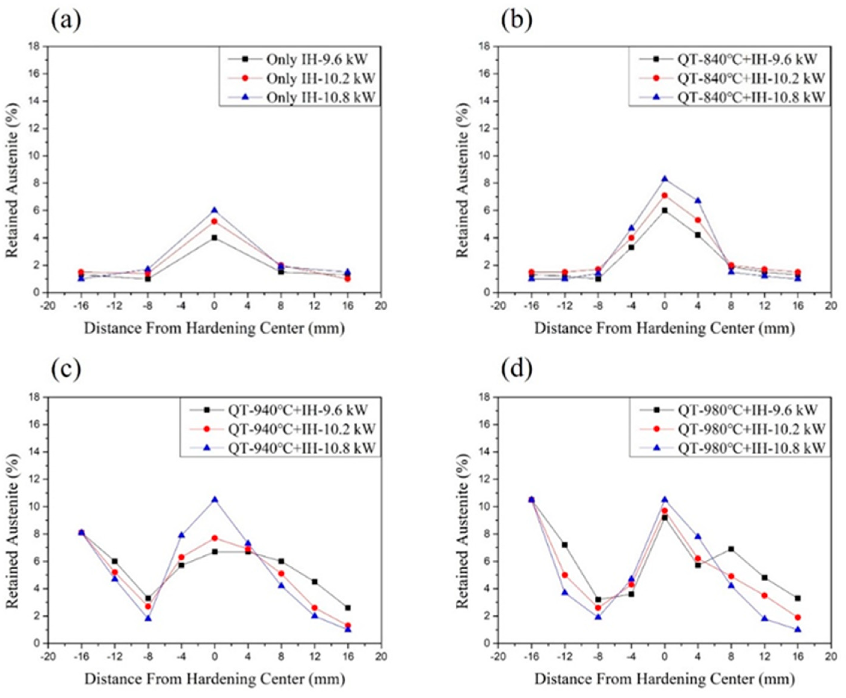
Figure 7 (a) shows the surface retained austenite content data of the as-received SUJ2 specimen after induction hardening. When the output power increases, the retained austenite content in the hardened area will also increase. This is because the higher the power, the amount of cementite solid-solved cementite in the austenite structure will increase during the heating process, and the carbon content in the martensite will also increase after cooling. The as-received specimens treated with 9.6 kW induction hardened output power have 3.9 % of the retained austenite content in the hardened center. The as-received specimens treated with 10.2 kW induction hardened output power have 5.1 % of the retained austenite content in the hardened center. The as-received specimens treated with 10.8 kW induction hardened output power have 6 % of the retained austenite content in the hardened center. As the distance from the hardening center increases, the retained austenite content will gradually decrease. This is because, in the heat-affected zone, the temperature raised during induction hardening may not reach the A1 line. Therefore, no retained austenite will be measured in the heat-affected zone after induction treatment.
Figure 7 (b) ~ (d) shows a higher retained austenite content at the hardening center than the specimen austenitized at 840 °C, 940 °C and 980 °C. The reason is also the proportion of cementite solid-solved into the martensite matrix increases after induction re-hardened. Therefore, due to the difference in carbon content within the martensite structure, there is a higher retained austenite content in the re-hardened area. The maximum retained austenite content in the hardened area will also increase with the austenitized temperature increase. In addition, the retained austenite in the heat-affected zone can be eliminated to a minimum of 2 %. As mentioned before, the heat-affected zone rises to a lower temperature (lower than the temperature of the A1 line) during induction hardening. After induction re-hardening, it has a similar high-temperature tempering effect to eliminate retained austenite, so the content of retained austenite measured in the heat-affected zone will be less.
4. Conclusion
From the microstructure observations, we know that increase in the austenitizing temperature, the proportion of cementite solid-solved in the martensite can be increased, and the volume of retained austenite will increase, too.
The microstructure of the material before induction hardening has a significant impact on the effective case depth under the same output power conditions. The effective case depth of the martensite structure after induction hardening is deeper than that of the spheroidized structure. The spheroidized structure was treated by the induction hardening method with 9.6 kW, the effective case depth is only 2.5 mm. If the microstructure is martensite before induction re-hardened treatment, the effective case depth of re-hardened specimens with induction power is 9.6 kW can reach less than 4.2 mm.
Because the hardened center by induction method will be subject to more severe temperature changes, the phase transformation caused by the supercooling driving force and the thermal stress caused by the temperature gradient is more effective. The hardened center area of induction hardening has the highest residual compressive stress value. The specimen was hardened by the induction hardening method with 10.8 kW, the surface residual compressive stress value of the hardening center can be reached to -766 MPa. As the distance from the hardening center increases, the residual compressive stress value will gradually decrease.
During the induction hardening process, the phase transformation of the martensite structure caused more internal stress due to re-hardening treatment than spheroidized structure transform to martensite. The maximum surface residual compressive stress value of austenitized at 980 °C and re-hardened with induction power is 9.6 kW specimen is -1073 MPa.
The SUJ2 specimen will have a wider stress influence range under the condition of the microstructure before induction hardening is martensite. The effective stress influence range in this paper of austenitized at 980 °C and re-hardened with induction power is 9.6 kW specimen can reach to 16 mm.
The heat-affected zone rises to a lower temperature than the hardened center region during induction re-hardening, it has a similar high-temperature tempering effect to eliminate retained austenite, so the content of retained austenite measured in the heat-affected zone will be less. The retained austenite in the heat-affected zone can be eliminated from 9 % to a minimum of 2 %.
References
- Fernandes, A. P.; Gallego, J.; Picon, C. A.; Filho, G. T.; Casteletti, L. C. Wear and corrosion of niobium carbide coated AISI 52100 bearing steel. Surf. Coat. Technol. 2015, 279, 112–117. [Google Scholar] [CrossRef]
- Hisakado, T.; Miura, K.; Suda, H. Effects of debris transfer and abrasive particle damage on the abrasive wear of hardened bearing steel. Wear 2001, 247, 24–32. [Google Scholar] [CrossRef]
- Matsunaga, H.; Komata, H.; Yamabe, J.; Fukushima, Y.; Matsuoka, S. Effect of Size and Depth of Small Defect on the Rolling Contact Fatigue Strength of Bearing Steel JIS-SUJ2. Procedia Materials Science 2014, 3, 1663–1668. [Google Scholar] [CrossRef]
- Ramesh, R.; Gnanamoorthy, R. Effect of hardness on fretting wear behavior of structural steel, En. 24, against bearing steel, En. 31. Materials & Design 2007, 28, 1447–1452. [Google Scholar] [CrossRef]
- Sun, J.; Wood, R. J. K.; Wang, L.; Care, I.; Powrie, H. E. G. Wear monitoring of bearing steel using electrostatic and acoustic emission techniques. Wear 2005, 259, 1482–1489. [Google Scholar] [CrossRef]
- Xu, D. H.; Kuang, Z. B. A study on the distribution of residual stress due to surface induction hardening. J Eng Mats Tech Ž. Trans ASME 1996, 118, 571–575. [Google Scholar] [CrossRef]
- Semiatin, S. L.; Stutz, D. E. Induction heat treatment of steel. ASM, Carnes Publication Services, 1986.
- Schopfel, A.; Storzel, K. Optimization of process parameters for induction heat treating by means of numerical simulation. In: Proceedings of the 17th ASM Heat Treating Society Conference including the 1st International Heat Treating Symposium, Indianapolis. 1997; pp. 595–600. [Google Scholar]
- Cunningham, J. L.; Medlin, D. J.; Krauss, G. Effects of induction hardening and prior cold work on a micro alloyed medium carbon steel. J Mats. Eng. Perf. 1999, 401, 407. [Google Scholar]
- Hu, Y.; Qin, Q.; Wu, S.; Zhao, X.; Wang, W. Fatigue resistance and remaining life assessment of induction-hardened S38C steel railway axles. International Journal of Fatigue 2021, 144, 106068. [Google Scholar] [CrossRef]
- Gao, J. W.; Pan, X. N.; Han, J.; Zhu, S. P.; Liao, D.; Li, Y. B.; Dai, G. Z. Influence of artificial defects on fatigue strength of induction hardened S38C axles. International Journal of Fatigue 2020, 139, 105746. [Google Scholar] [CrossRef]
- Komotori, J.; Shimizu, M.; Misaka, Y.; Kawasaki, K. Fatigue strength and fracture mechanism of steel modified by super-rapid induction heating and quenching. International Journal of Fatigue 2001, 23, 225–230. [Google Scholar] [CrossRef]
- Hayama, M.; Kikuchi, S.; Tsukahara, M.; Misaka, Y.; Komotori, J. Estimation of residual stress relaxation in low alloy steel with different hardness during fatigue by in situ X-ray measurement. International Journal of Fatigue 2024, 178, 107989. [Google Scholar] [CrossRef]
- Areitioaurtena, M.; Segurajauregi, U.; Fisk, M.; Cabello, M. J.; Ukar, E. Influence of induction hardening residual stresses on rolling contact fatigue lifetime. International Journal of Fatigue 2022, 23, 106781. [Google Scholar] [CrossRef]
- Huang, M.S.; Huang, Y.L. Effect of multi-layered induction coils on efficiency and uniformity of surface heating. International Journal of Heat and Mass Transfer 2010, 53, 2414–2423. [Google Scholar] [CrossRef]
- Cao, Y.J.; Sun, J.Q.; Ma, F.; Chen, Y.Y.; Cheng, X.Z.; Gao, X.; Xie, K. Effect of the microstructure and residual stress on tribological behavior of induction hardened GCr15 steel. Tribology International 2017, 115, 108–115. [Google Scholar] [CrossRef]
- Torkamani, H.; Vrček, A.; Larsson, R.; Antti, M. L. Micro-pitting and wear damage characterization of through hardened 100Cr6 and surface induction hardened C56E2 bearing steels. Wear 2022, 492-493, 204218. [Google Scholar] [CrossRef]
- Schüßler, P.; Damon, J.; Mühl, F.; Dietrich, S.; Schulze, V. Laser surface hardening: A simulative study of tempering mechanisms on hardness and residual stress. Computational Materials Science 2023, 221, 112079. [Google Scholar] [CrossRef]
- Li, H.P.; Sun, Y.; He, L.F.; Li, Z.C. Failure analysis of ball screw in the progressive induction hardening and finishing machining. Engineering Failure Analysis 2023, 151, 107410. [Google Scholar] [CrossRef]
- Mühl, F.; Damon, J.; Dietrich, S.; Schulze, V. Simulation of induction hardening: Simulative sensitivity analysis with respect to material parameters and the surface layer state. Computational Materials Science 2020, 184, 109916. [Google Scholar] [CrossRef]
- Totik, Y.; Sadeler, R.; Altun, H.; Gavgali, M. The effects of induction hardening on wear properties of AISI 4140 steel in dry sliding conditions. Materials & Design 2003, 24, 25–30. [Google Scholar] [CrossRef]
- Kristoffersen, H.; Vomacka, P. Influence of process parameters for induction hardening on residual stresses. Materials & Design 2001, 22, 637–644. [Google Scholar] [CrossRef]
- Song, C.; Yang, C.; Hu, S.; Yin, F. Numerical modeling of ultrasonic shot peening with an accurate impact velocity. Journal of Manufacturing Processes 2023, 101, 982–989. [Google Scholar] [CrossRef]
- Delbergue, D.; Texier, D.; Lévesque, M.; Bocher, P. Comparison of Two X-Ray Residual Stress Measurement Methods: Sin2 ψ and Cos α, Through the Determination of a Martensitic Steel X-Ray Elastic Constant. Materials Research Proceedings 2017, 55–60. [Google Scholar]
- Miyazaki, T.; Sasaki, T. A comparison of X-ray stress measurement methods based on the fundamental equation. Journal of Applied Crystallography 2016, 49, 426–432. [Google Scholar] [CrossRef]
- Ao, S. S.; Li, C. J.; Huang, Y. F.; Luo, Z. Determination of residual stress in resistance spot-welded joint by a novel X-ray diffraction. Measurement 2020, 161, 107892. [Google Scholar] [CrossRef]
- Miyazaki, T.; Fujimoto, Y.; Sasaki, T. Improvement in X-ray stress measurement using Debye–Scherrer rings by in-plane averaging. Journal of Applied Crystallography 2016, 49, 241–249. [Google Scholar] [CrossRef]
- Tanaka, K. The cosα method for X-ray residual stress measurement using two-dimensional detector. Mechanical Engineering Reviews 2019, 6, 378. [Google Scholar] [CrossRef]
- Ramírez-Rico, J.; Lee, S.; Ling, J.; Noyan, I. C. Stress measurement using area detectors: a theoretical and experimental comparison of different methods in ferritic steel using a portable X-ray apparatus. Journal of Materials Science 2016, 51, 5343–5355. [Google Scholar] [CrossRef]
- Borchers, F.; Meyer, H.; Heinzel, C.; Meyer, D.; Epp, J. Development of surface residual stress and surface state of 42CrMo4 in multistage grinding. Procedia CIRP 2020, 87, 198–203. [Google Scholar] [CrossRef]
|
Disclaimer/Publisher’s Note: The statements, opinions and data contained in all publications are solely those of the individual author(s) and contributor(s) and not of MDPI and/or the editor(s). MDPI and/or the editor(s) disclaim responsibility for any injury to people or property resulting from any ideas, methods, instructions or products referred to in the content. |
© 2024 by the authors. Licensee MDPI, Basel, Switzerland. This article is an open access article distributed under the terms and conditions of the Creative Commons Attribution (CC BY) license (http://creativecommons.org/licenses/by/4.0/).
